 |
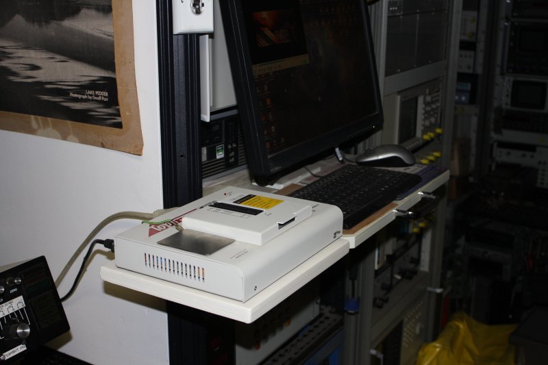 |
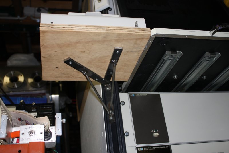
In mid July some major projects were going well, plus I'd finished some minor side-projects. The searchlight fix worked, I'd examined and packed away the goodies I'd received then, made a quickie new shelf for my IC programmer, and painted the dolly that I'd had to leave bare for the road trip to Albury in April.
Why not start something new? I thought I'd begin restoring the big old Macson lathe I recently bought. That one's project dependency tree is like this:
1  The vacuum chamber project needs some large diameter parts machined.
   (Big aluminium rings, about 300mm dia and 50mm thick, with various holes.)
2   My existing lathe is far too small to do them.
3    Search for & buy a bigger lathe. A saga in itself.
4     Which spun off the "$1 UPS" project tree.
5      Progress the 'Forge Shed' work space for the big lathe.
6       Build an extension on the 'Forge Shed' for more storage space (and the UPS.)
7        Refurbish and set up the lathe.
8         Find and buy blanks for the rings, and machine them. Non-trivial work.
Currently #4 is on hold, steps 5 & 6 are active. At this point I can't really do much on the lathe itself, while those constructions are incomplete.
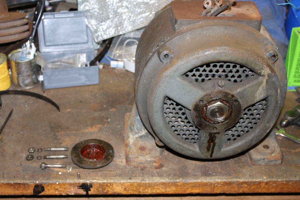
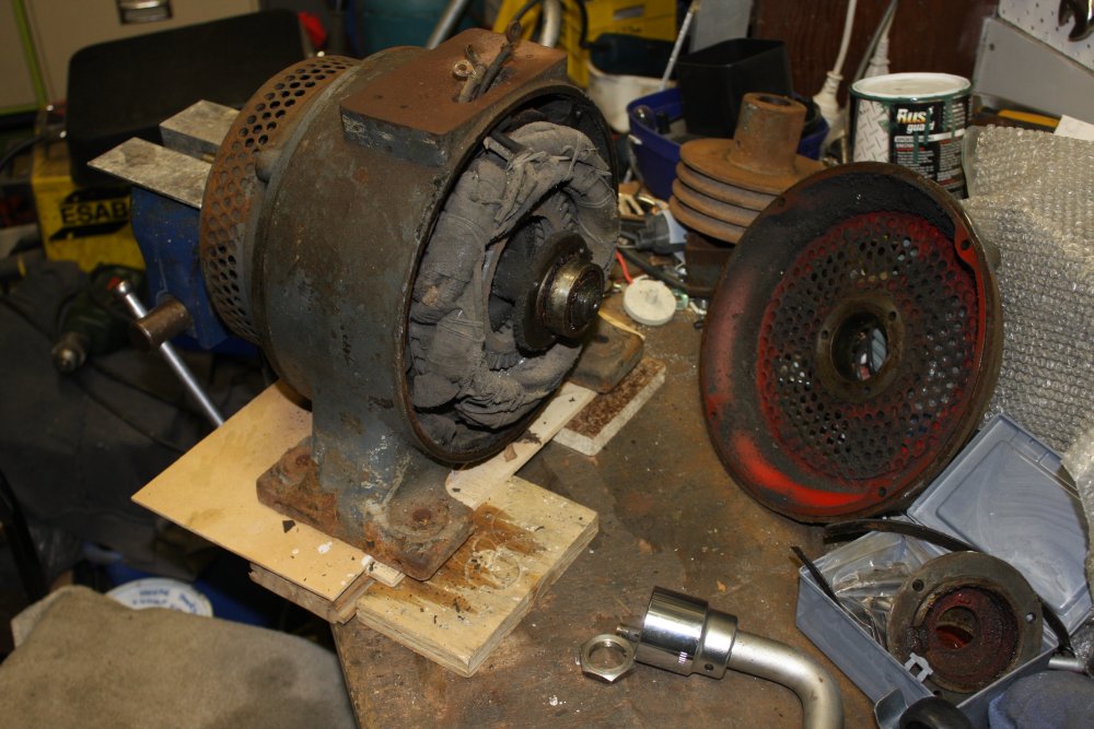
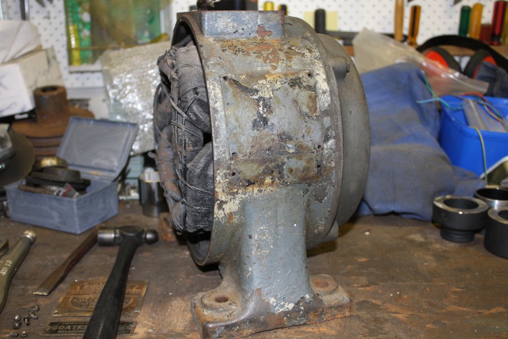
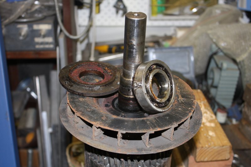
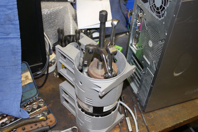
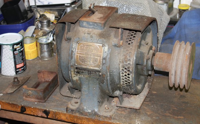 But my existing small metalworking shop is relatively clear atm, and the large old 3-phase motor for the lathe is waiting, looking rusty, dusty and unloved.
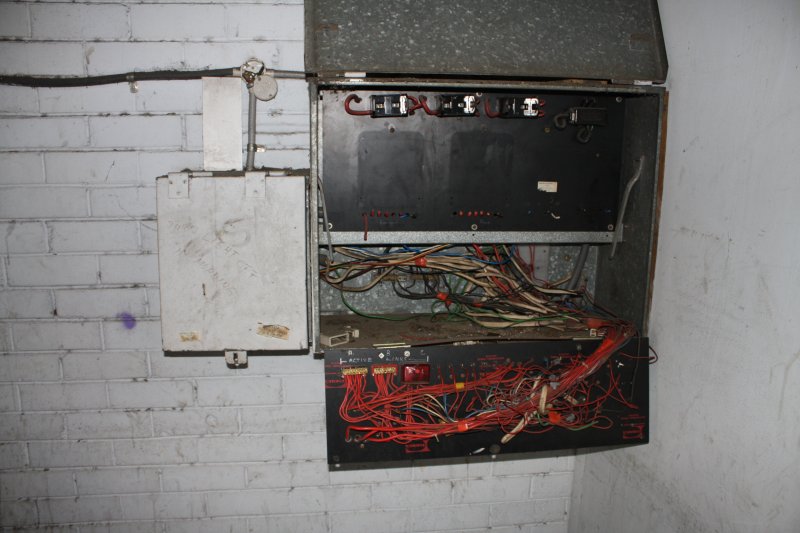
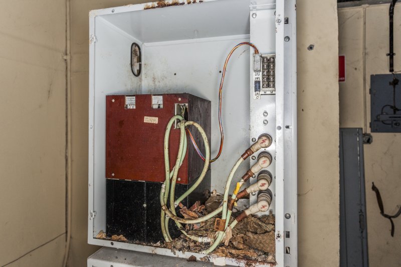
The junction box is removed, with a broken mounting and three loose wires sticking out. Their insulation is very old crumbling rubber and cloth. Typical for 1950s construction.
Does it work? Can it be refurbished and still working? (ie me not breaking it.)
The suspence is unbearable. Let's take it apart and find out.
That was on 20180716.
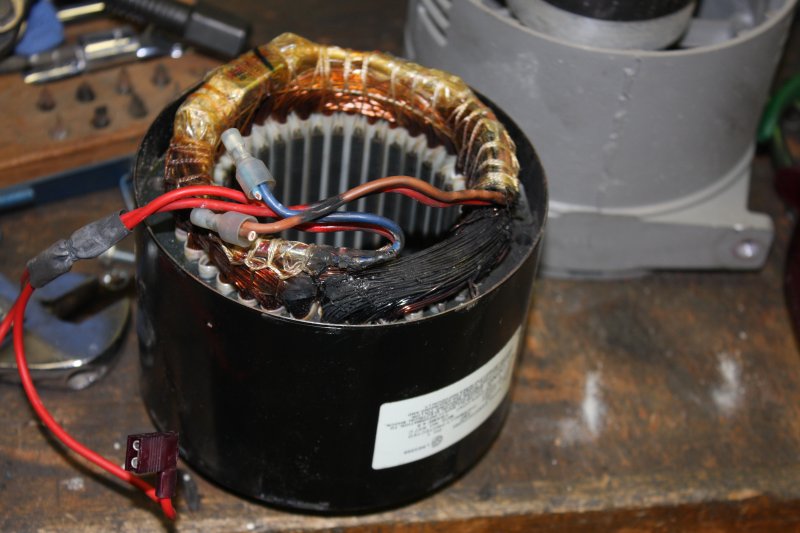
First check the windings with a multimeter. The winding resistances are all OK and same, and the low voltage multimeter can't detect any leakage from windings to frame. Good. I'll do a HV leakage test later.
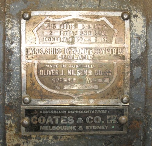 I like this motor, and think we have a lot in common. It's from the early 1950's and is probably as old or a bit more than me. It looks antique, as I do. It's the original motor for the lathe, stylistically matches, and has the mounting hardware plus protecton shields against metal chips. Definitely worth attempting a full restoration.
The plan is to completely disassemble the motor, clean out the dust, remove and pretty up the nameplate, remove all the old flaking exterior paint and rust, rebuild the junction box, clean, check & relube the bearings, repaint the casing, reassemble and test.
All while being extremely careful to not damage the pole windings and their fragile aged insulation. I expect to be using a sand blaster to remove old paint from much of the lathe and want a uniform painted appearance, so will attempt to do the same with the motor. Sandblasting and electrical wiring insulation are natural enemies, so that will be the number one caution.
 |
 |
 |
 |
 |
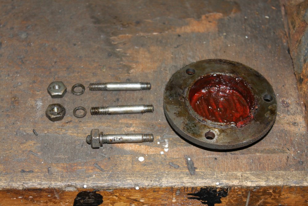
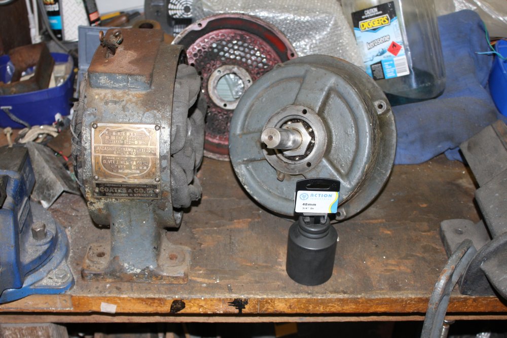
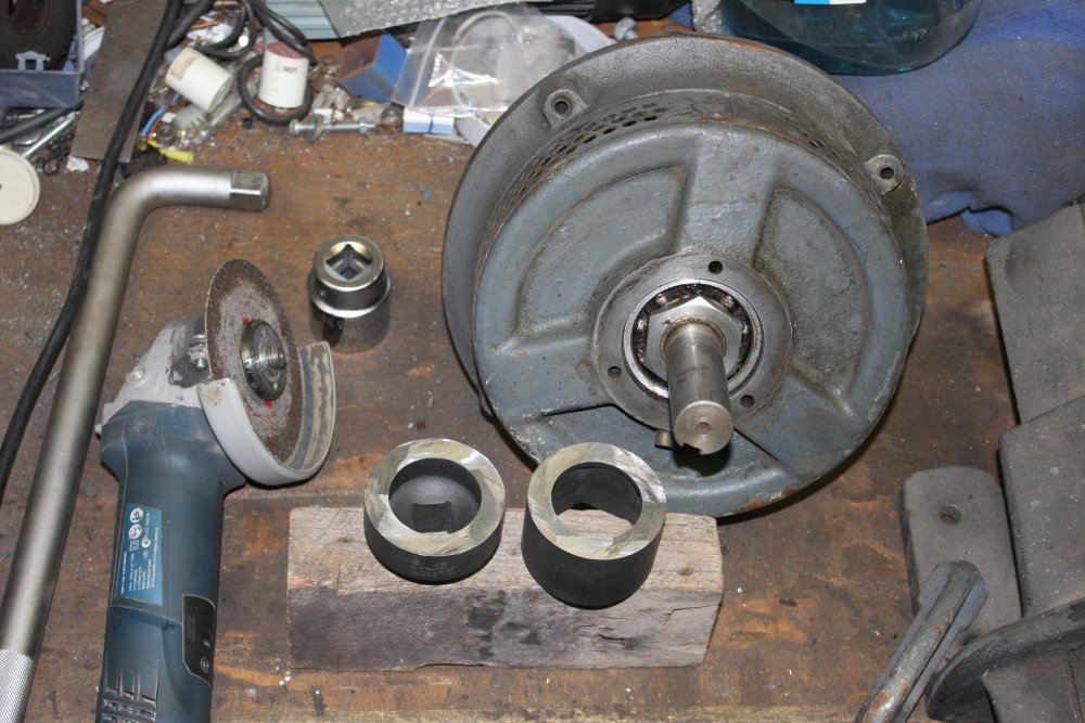
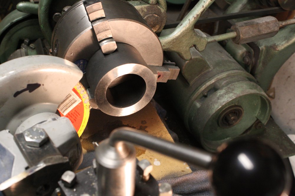
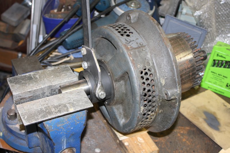
1 - 3. The first snag encountered was discovering that the motor shaft has two large lock nuts keeping the ball bearing inner races compressed to the shaft steps. Both of them are too big for any socket wrench I have, plus the pulley end one needs a very deep socket to fit over the shaft end. They are both recessed into the frame, so a big shifter or ring spanner can't be used.
Naturally the nuts are in imperial dimensions. 35.3mm and 47.2mm (probably 1 3/8" and 1 7/8" ?)
I refuse to buy large expensive anything in imperial, so I bought two metric sockets, one a standard 36 mm and the other a 'deep' impact socket wrench of 48 mm.
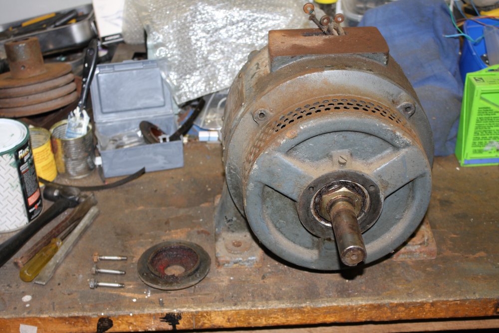
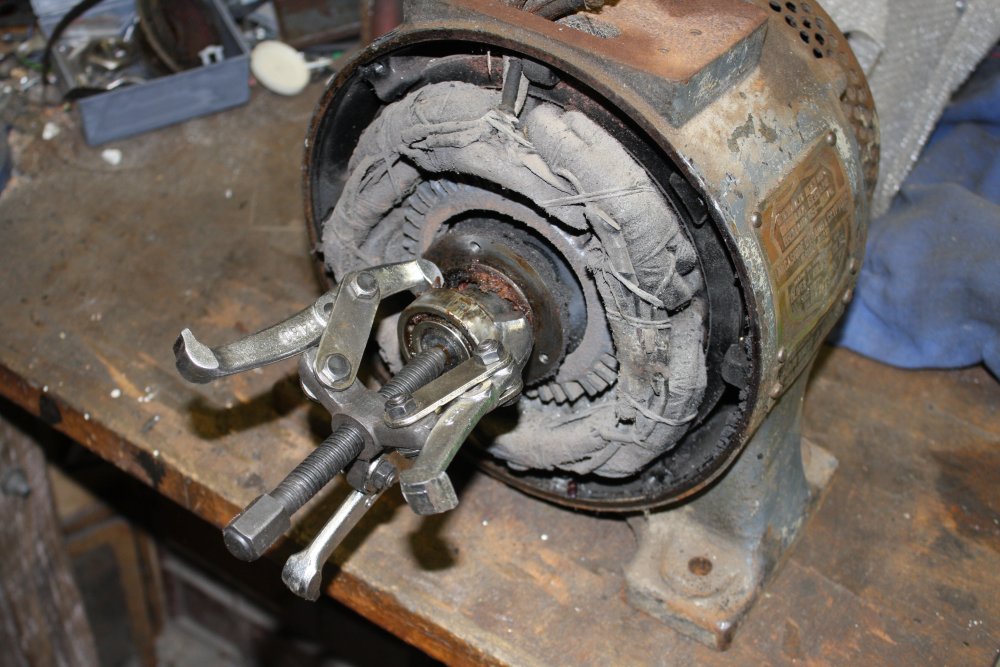
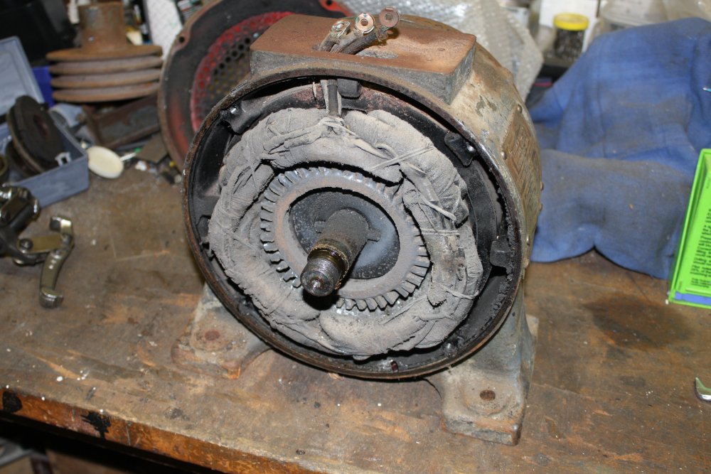
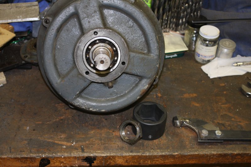
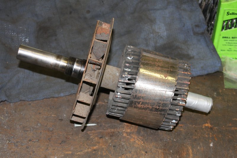
4, 5. The smaller one took the rear-end nut off the shaft easily. So now the motor came apart, and I could see the windings for the first time. They look OK.
 |
 |
 |
 |
 |
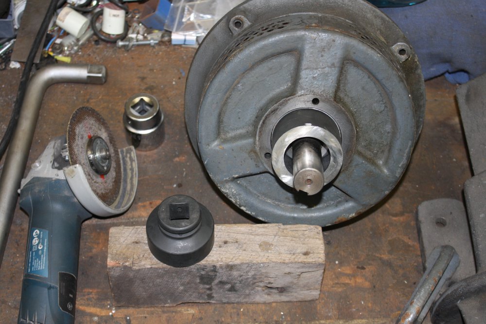
1, 2. Bearing removal.
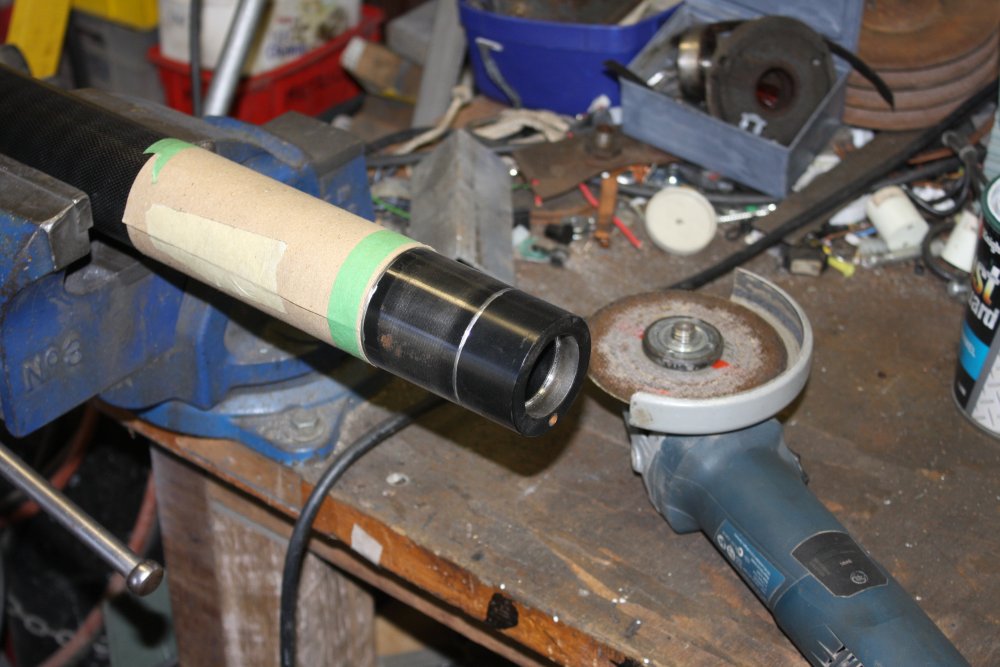
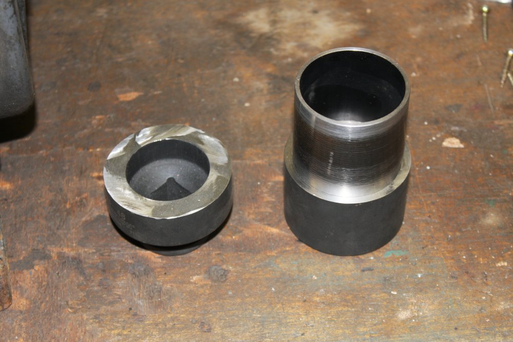
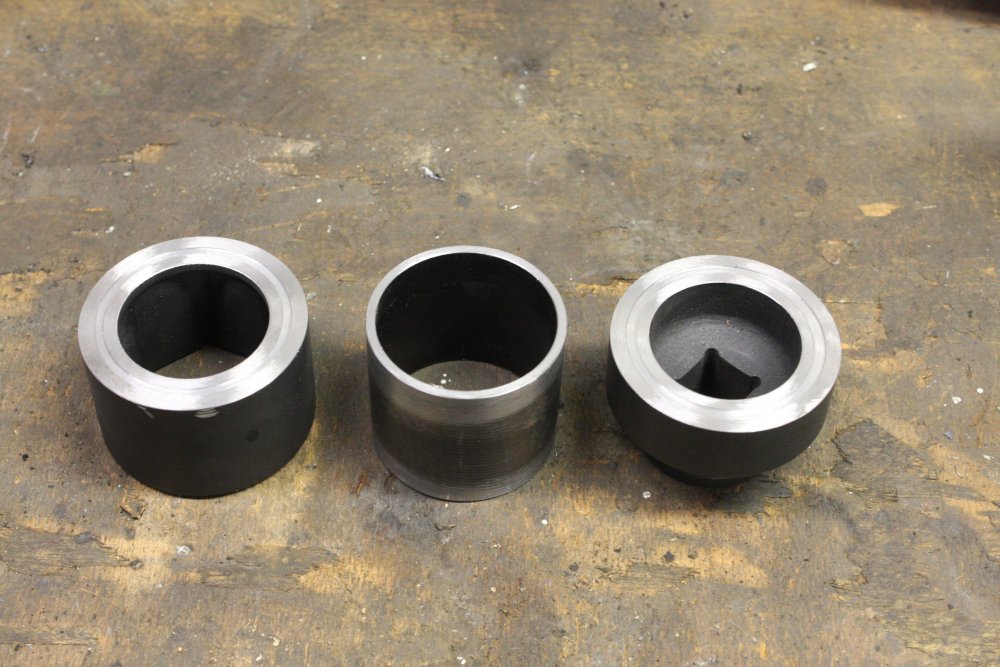
3. The larger nut on the shaft, and the nice 48mm impact deep socket wrench, that still can't reach the nut. But I'm going to make it reach.
4. Starting with cutting it in half. Marked a pencil line evenly around the cylinder, cut it by hand to the line by eye with a thin cutting wheel in an angle grinder.
5. The socket halves.
 |
 |
 |
 |
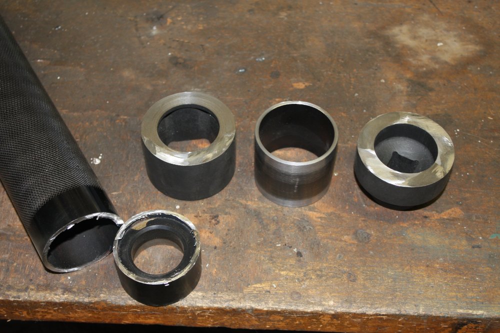 |
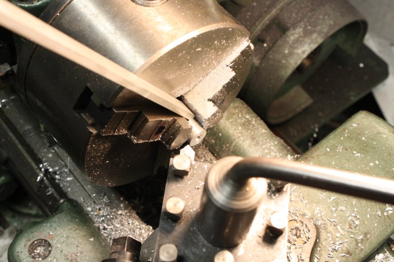
1. The cut was fairly clean, and now half the socket fits on the nut.
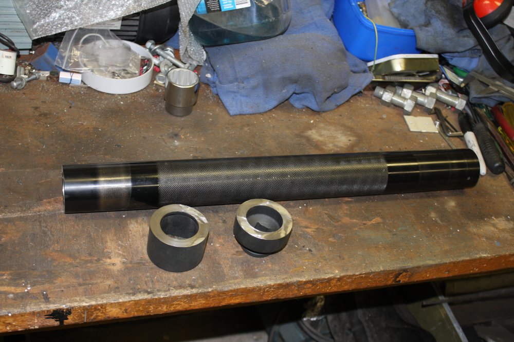
2. The next step is to add the extension piece. In my steel stock I found a roller from an exercise treadmill, that is a suitable diameter and fairly thick walled.
The cut ends of the socket also need to be turned in the lathe to a true flat. I expected machining the steel of an impact wrench in the lathe with a silversteel cutting tool would be problematical, and wasn't wrong. Using a very slow cutting speed to minimize heating of the bit (I don't have cutting/cooling fluid feed on my lathe yet) it worked for a little while, but blunted the cutting edge before I finished the whole surface. That was the left one in this pic.
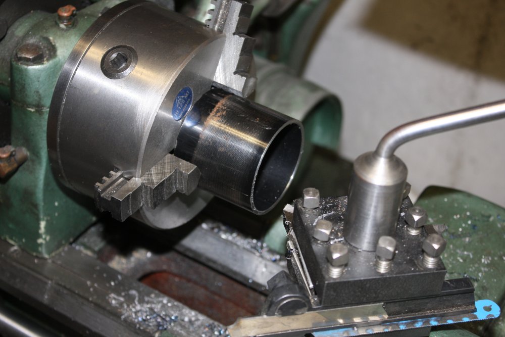
3 - 5. Cutting and facing a section of the tube.
 |
 |
 |
 |
 |
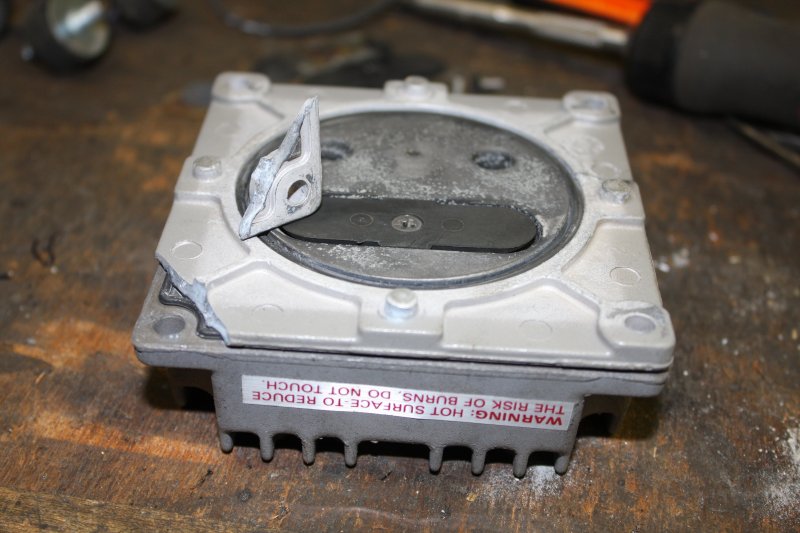
1, 2. A detour. I'd taken the motor frame to local motor repair factory to ask about the possibility of extracting the pole piece with its coils, from the motor outer frame. They were assembled by heating the frame and slipping it over the cold pole piece. As the frame cools and shrinks it makes a tight fit on the inner pole piece. I wondered if the motor experts thought it was possible to reverse that process, so I could sand blast the frame without risk of damaging the windings.
Their advice: no, virtually impossible to heat the frame without also heating the closely contacting pole-winding assembly. Which will damage the windings. Better to sand blast it in one piece, but protect the windings with something.
Then while driving home I spotted a kerbside rubbish pile with several rolls of old deep pile carpet. Grabbed one, hoping this will work as sandblasting protection. (But I'll test it before trying on the motor!)
During that discussion I'd also noticed that the holes for the securing pins on the nameplate don't go all the way through the frame. So they can't be punched out from inside, even if I could extract the pole piece. Their heads are featureless domes, intended to prevent getting a grip on them. Those pins are intended to not be removable.
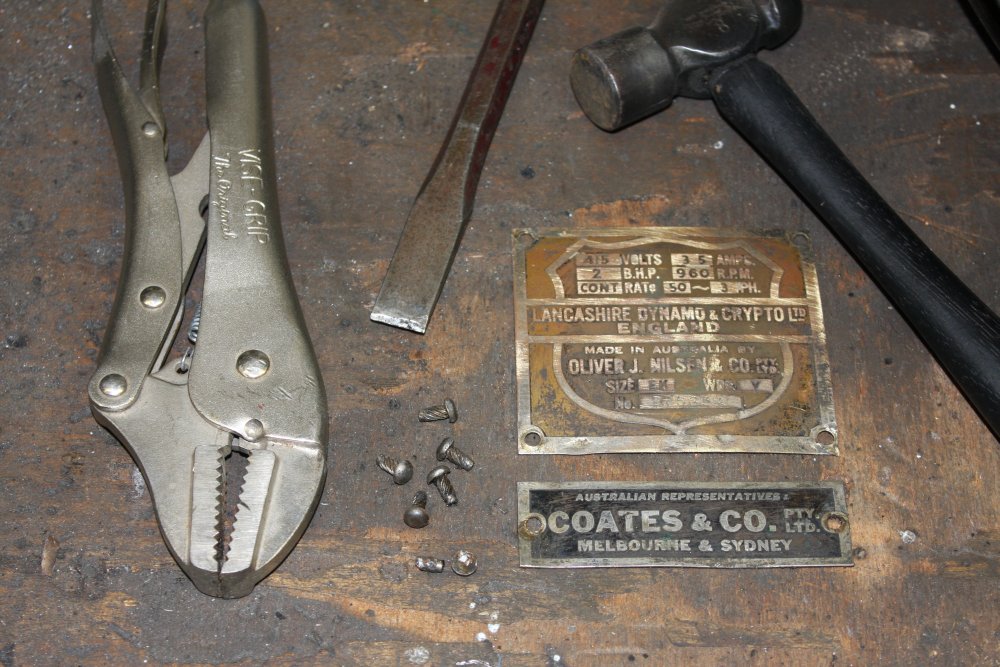
Discussing the nameplate pins problem on eevblog forum, led me to try getting them out via another method. I didn't want to damage the pins, so grinding slots or flats on their heads was out. That left a method which won't work in some cases — using a sharp cold chisel to tap the heads sideways, working around the pin head (loosening the spiral teeth in the case hole) while also attempting to get the chisel point under the edge of the head to work it upwards a little bit. While trying not to damage the soft brass nameplate.
With the pin slightly loosened and lifted a fraction, there is a tiny lip for vicegrips to grab. If they can get a grip, it allows the pin to be rotated and pulled to 'unscrew' it.
It worked! All of them came out, and the nameplates are not damaged. One pin's head was already partially sheared off, I think from the original hammering in. There was just enough stub protruding to get that one out too. Lucky! The metal of these pins is extremely hard, and can't be drilled out.
3. How I want the socket extension tube to fit. But first those faces need to be cleaned up. In steel that rapidly blunted a silversteel cutting bit.
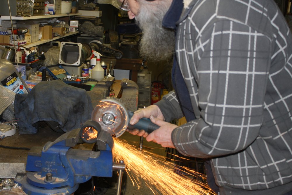
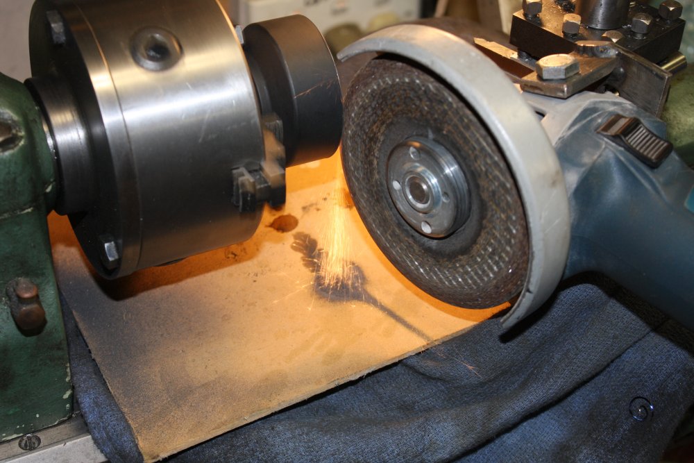
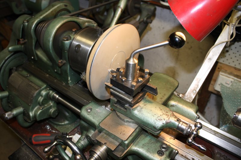
4, 5. I could have just repeatedly resharpened the cutter, or tried using a tungsten carbide cutter, but decided to switch to grinding. I had a previously made holder for an angle grinder, allowing it to be mounted to the lathe tool post. A crucial detail is to cover everything to prevent grit penetration into the saddle slides, lead screws, etc. And then put a board over the covers, so the jet of sparks doesn't burn through them.
Things to bear in mind:
- Don't force it. Light passes only, or the grinding wheel will break.
- It's essential to avoid getting grinding grit in any of the lathe's sliding joints or screw threads. So a cloth cover over everything. And then a wooden board over the cloth where the grinding sparks stream will hit. To prevent the cloth catching fire.
 |
 |
 |
 |
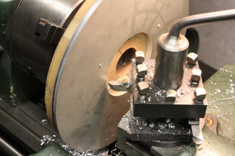
1. That works. Here's an adequately cleaned up surface.
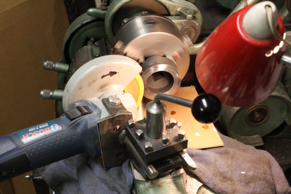
2. The socket faces need locating grooves for this tube. I used a parting off tool as a cutting bit, and it did the shallow grooves OK without going blunt. I didn't measure anything, just marked the approximate position of the tube with a felt pen, and iteratively cut the grooves till the tube ends fitted. Only thing that matters is that the tube be centered, and the lathe takes care of that.
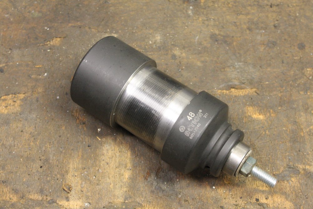
3. Then the tube and two socket pieces must be held together firmly for welding. Getting a bolt mounted down the center required a couple of odd 'washers' one hexagonal and one square. Both were hand cut from a bit of scrap.
4. The completed assembly, ready for welding.
With that done, next question is how pretty do I want the welds?
I could just MIG weld the seams by hand, running in short beads around the circumference, stopping multiple times to rotate the assembly in the vice. This will look awful. I know my welds, it will be disgusting. This is the 'quick, easy, and shitty' option. I'm very tempted...
I do have a pipe rotator I improvised back in 2009 when welding some stainless steel railings. But, I don't see how this socket thing could work in that. I'm not even sure the drive would be strong enough for this quite heavy object.
And in future I do need a more generic solution to doing circumferential clean welds, for later work on the vacuum system. So, lets see if I can come up with something a bit more versatile. 'Quickly', ha ha.
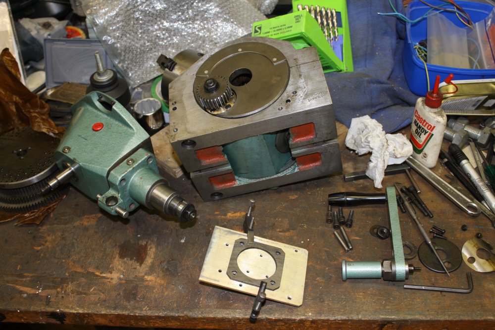
As it happens I have a quite nice 'Multipurpose Indexing Head.' It's an attachment for lathes and milling machines. I bought it many years ago along with a big rotary table, at a distressed sale by a nearby machinery importer (who went broke soon after.) It's Russian made, a cheap-arse for-export product of the old USSR, and about as clunky as can be expected. But though it's unable to hold an oil-fill (leaks like sieve) it does seem to work. At least probably; I've never put it to serious use.
Does my socket-construction fit in the Indexer's chuck? Yes!
For this I need to understand the details of what goes on inside the Indexer. How feasible is mounting a stepper motor on the drive shaft? Why does the drive shaft have so much gear play, and can that be adjusted? Can I improve the oil-tightness of this thing? Since if I'm going to motor-drive it, it must be able to hold some oil.
 |
 |
 |
 |
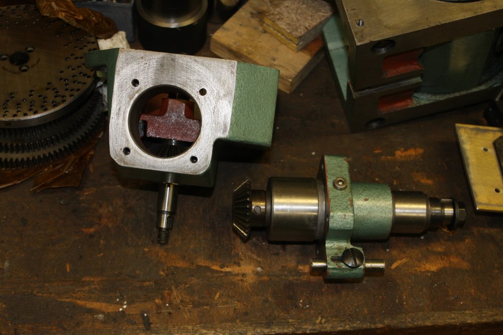
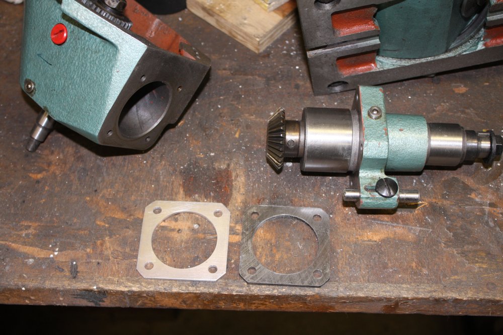
1 - 3. It turned out the shaft play was due to a spacer that was too thick. It was 4mm, giving insufficient mesh in a pair of 45° bevel gears. Experimenting, 3mm worked a lot better. I made a replacement spacer from some aluminium plate. Then reassembled the Indexer with some silastic in the seals that are probably the worst oil leak points. Fingers crossed.
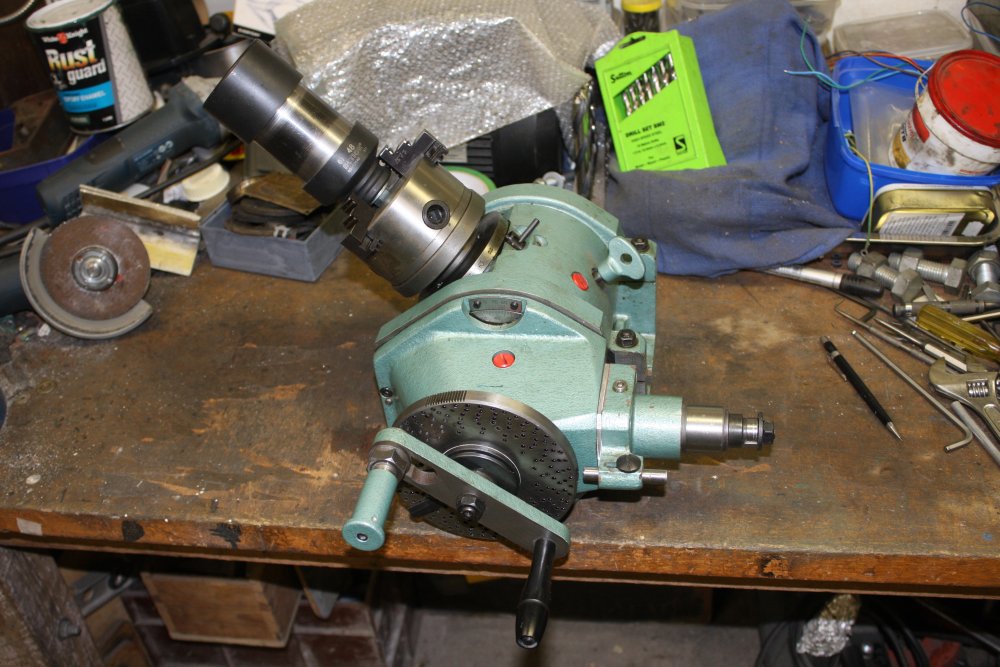
4. The indexing head set up to hold and rotate the socket & extension for welding.
 |
 |
 |
 |
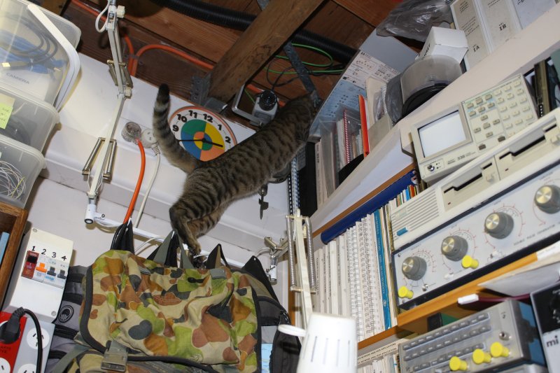
The unexpected! A lovely young cat showed up and adopted me. Totally a wild stray, about 6 months old, but took just a few days to decide she likes it here, the giants are friendly and they give food. Well good, I could do with some cheering up. Her tentative name is Mist, but as I come to know her better, something between Lightning and Mischief would be more suitable.
How about the index head motorizing? What I want is a way to rotate the piece at an adjustable stable speed, that doesn't vary with changing loading. Also future ability to do precise software controlled angular movements. This means a software controlled stepper motor. For the present use a fairly small stepper will do; it only needs to overcome friction in the indexer gearing since welding imposes no mechanical forces. I can upgrade to a larger motor and electrical drivers in future for indexed machining if needed.
 Back when I bought a 3D printer, I'd made sure to buy one with fully open source hardware and software.
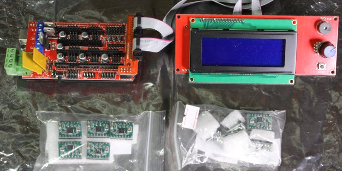
Plus bought a complete spare set of the driver electronics. It's Arduino-based, with an open-hardware motor drive board called RAMPS 1.4.
This is the RAMPS board, LCD UI, A4988 stepper drive modules, and an Arduino Mega2560 (underneath the RAMPS.)
The intention was to use this as a learning platform for software development for general stepper motor driving, needed for several current and future projects. But naturally I hadn't got around to it.
All right, now is the time to try that.
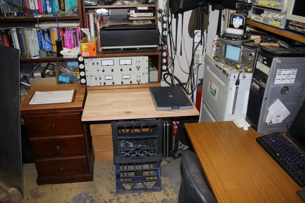
Ha ha, but of course there is a hitch. It's winter in Oz and I recently started using the wood-burning heater near my PC desk. Which meant moving away some things that were too close to the heater. Including the side-table next to my desk. That was always too long, and awkward to move. When in place it obstructs a file cabinet and set of drawers, so being unable to easily move it out of the way is a huge pain. With the wood-burning heater in use, it was completely untenable.
 |
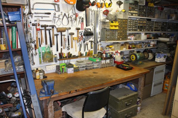
Yes, this room layout is cramped and poor.
Btw, the bits of random scrap metal on top of the heater are there to prevent cats from jumping on top of it while it's running. Yes, it happened once. Poor cat burned all the skin off her paw pads, and took weeks to heal. Hot metal is not in their instinct set.
The aluminium sheets are serving as heat reflectors, so the bookshelf doesn't catch fire.
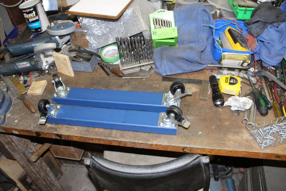
Anyway, a side table is essential. Apart from this and every other project at my main desk needing that surface, it's where my scanner sits when I use it. However a new table must be smaller and more mobile than the other one. Something custom made to fit. Cheap and quick. Castor wheels, but lockable.
So funny. For refurbishing a big antique motor, here I am about to do some wood and metal furniture construction, then a barely-related software project. Again.
Here's the plan:
- Make desk side bench.
- Set up arduino + RAMPS + LCD + power supply.
- Find & evaluate aduino software dev environments.
- Direct assembler for the CPU.
- Arduino dev UI. - Establish coms from PC to arduino.
- Load some test software into arduino, check working with LCD. (The 3d printer set?)
- LCD text interface --> Hello world?
- See if any software exists for this hardware set to just drive a stepper motor at fixed rate.
Otherwise write it. - Mount a stepper motor on the indexing head.
- Improvise an adjustable holder for the MIG welder torch, to suit a turning object in the indexer.
- Weld the socket extension.
- Undo the motor shaft nut using the newly made extender.
- Continue with the motor refurbish.
I wonder if this will hold up to the blowtorch of practical execution?
If it explodes into a big 'battling with flakey software utilities and poor documentation' screw-around, I can bail and just weld the thing by hand.
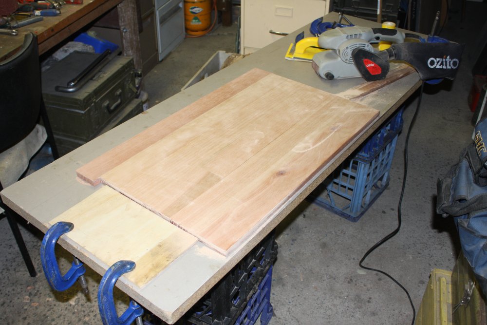
I wanted a table top around 700 x 500mm (plus or minus something vague.) Much bigger won't be easily moveable out of the space, any less is too small for a workspace. A scrap timber benchtop I had in the lumber pile turned out to be cracked, and on trying to fully split the crack to re-glue, it splintered hopelessly. That got cut up and used for firewood tonight.
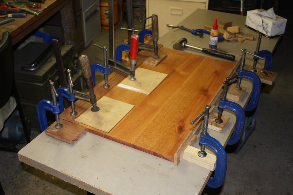
So, off to Bunnings hardware. Where benchtop panels they have turn out to be either way too big, or too small in the depth dimension. Best compromise was a Karri wood panel 1200 x 405 mm, for $40. I cut the length to 750mm, and glued on a strip of hardwood flooring to get the depth up to 475mm (enough.)
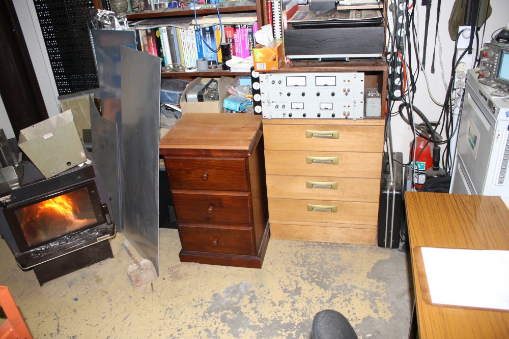
That makes a second cool coincidence lately. Right after I'd moved the old side table elsewhere, I'd thought that now the space could do with another small set of drawers. The first coincidence was that same day finding a street-tossed drawers unit, that fitted the space nicely. And it's real wood, not chipboard. Perfect!
That is the dark brown drawers unit in the room photo above. And there sitting on top is the second cool coincidence. The top of that unit is a bit lower than the main desk and side table. It would be better if the same height, but I don't want to modify the unit. It needs a build-up spacer just sitting on top.
Annnnd... the offcut from that Karri wood panel fits the top very nicely, in both directions, and brings it to the right height. This was totally a fluke. Cool.
 |
 |
 |
 |
 |
1. Glueing the extra wood strip onto the table top panel.
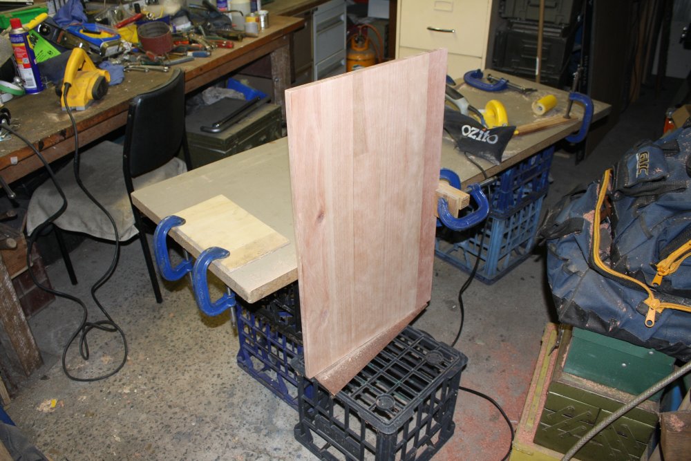
2, 3. Sanding down.
4. Where the new table will go.
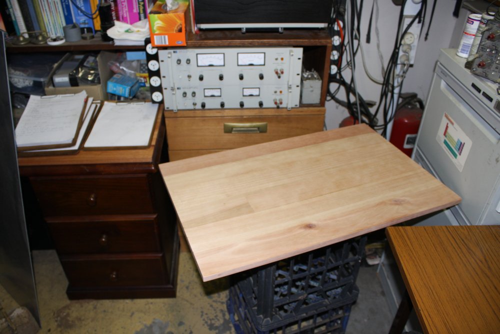
5. Checking it does actually rotate and fit out through the gap.
 Doh!
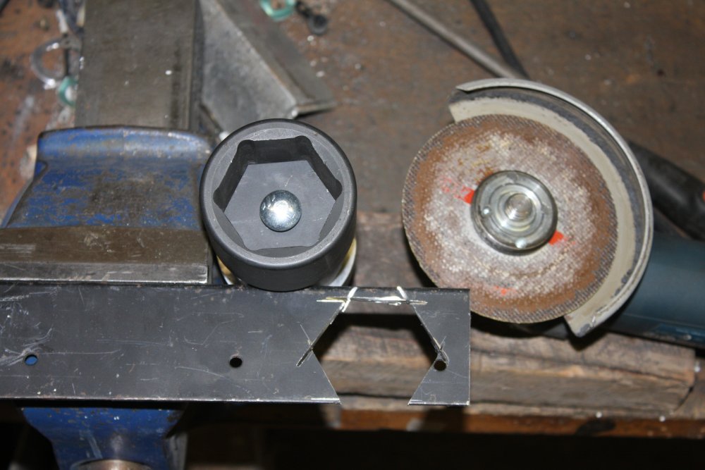
Doh!Here's an example of why just charging into things without much thought can be less than optimal. So I'd bought a 48mm socket wrench for $50 (cheap!) with the idea of cutting and extending it. I was thinking the result still needed to be very strong, take a torque wrench, etc. Hence immediately cutting it at the best point for 'extending.'
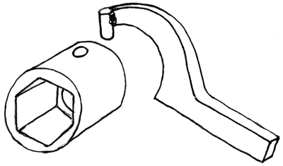
But if I'd considered it more, I might have realized that the method at right would have worked. In which case I should have cut it leaving all the thick cylindrical part and the hex socket together. Then drilled holes in the thick part to take a couple of bars like so.
The place I cut it, didn't leave enough 'thick bit' to do that.
I could still just weld bars or flats onto the back of it. Hmmm...
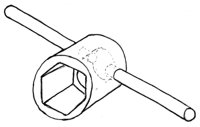
Later: Ah! I see an even better way to do it, that should be fine for dealing with the motor shaft nuts.
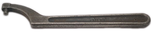
 A Pin Wrench. I guess if the guy who wrote that made a mistake with the terminology, I can be forgiven for not thinking of this solution immediately.
But still, how embarrassing.
 |
 |
 |
This table is a case in point. The top is size constrained by the existing furniture arrangement, so that required improvisation with what was available, without needing much thought. Final size is 750 x 475 mm.
I'd already bought the lockable castorwheels and some steel suitable for the wheels base (an about-right length offcut from the racks at the steel shop, with a width that suited the castor wheels flange.) Again, existing constraints meant not much thought required.
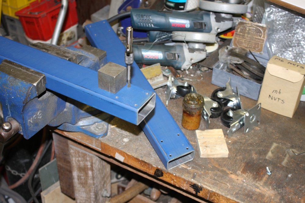
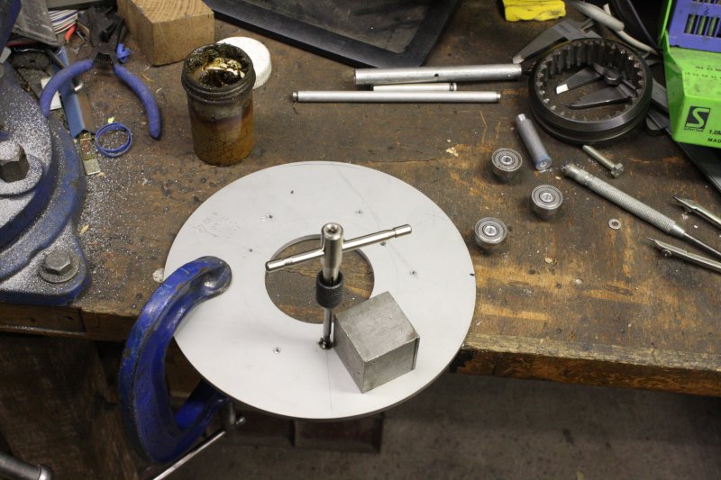
Cutting the base side pieces also didn't require thought — they should be the same depth as the table top. And the wall thickness is 3mm, so I can just tap the castor mounting holes, with screw size of M6 determined by the hole size in the castor flanges. Simple. Pics 1 & 2 are that all done.
Incidentally, the steel cube in pic 1 is there to serve as a visual aid for starting the tap perpendicular to the steel surface.
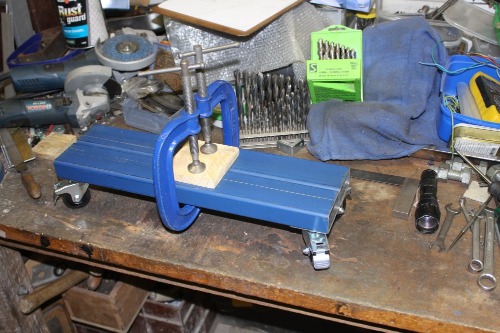
Pic three arrangement was to measure the height from ground to the top of the base pieces. Because now I have to think about the details of whatever goes between the base and the table top. And this involves a lot more consideration, if it's to work out nicely.
What do I want, exactly? A simple fixed height, always flat table? Or would it be better if adjustable height? My main desk is currently a temporary thing, intended to be replaced in future. Among other things a future desk would be better if a centimeter or two higher. After which the side table won't match, if it's not adjustable.
Then it occurred to me, that this thing is about the size of a small drafting table. I have a clamp-on drafting arm, that would be nice to use here sometimes. For this and some other uses, it would be good if the table top could be adjustably tilted. If I can arrange for that easily. The height adjustment is important, the tilting top is just an appealing idea.
While sketching out some table structure ideas late in the evening, is when the better idea for the socket wrench popped up.
Urrgh. Well, let's get the table finished, then decide whether to do a quick weld and ditch the whole Indexer and stepper motor drive thing, or stick to the plan.
Easier said than done. How to make the table variable height, on top of a castor wheel base? Something between the base and the benchtop has to be 'extensible.' But solid when locked in position. Hmmm...
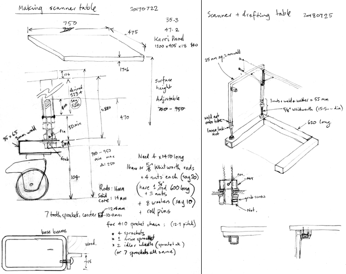
The first rough idea had the four corner vertical frames with threaded bars forming their lower parts, much like the screw-down supports I always put on rack roller frames.
Obviously this would be a pain to adjust, since all four rods would have locknuts to be loosened, then the threaded rods turned equally, then locked again. It would rarely need doing, but still... could I link them together?
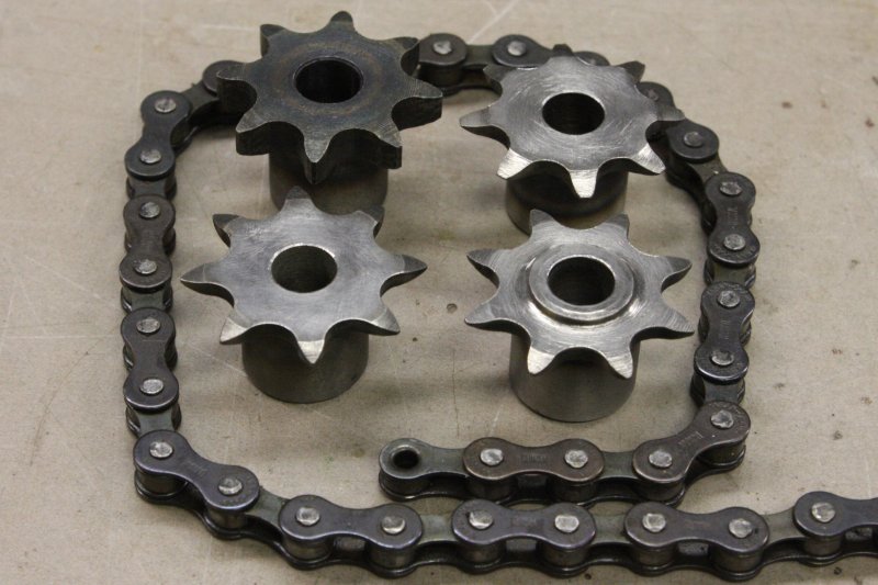
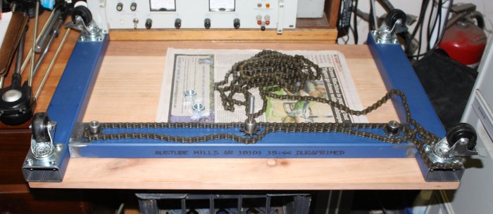
I have a large amount of '410 sprocket chain' (same as bicycle chain, I thought.) If I could find some small sprockets to suit it, I could fit all the sprockets and chain inside the quite large base frame. Then have either a winder sprocket, or just turn one rod, have them all turn together.
You'd think generic sprockets to fit bicycle chain would be common. But no. Quite a bit of googling and trawling through various online catalogs of sprocket chain later, I'd achieved nothing except learning there are a million kinds of sprocket chain, all slightly different. And damned few suppliers of suitable sprockets. Not even Aliexpress helped. Also that 410 chain I have, is not quite the same as bicycle chain. Same pitch, but slightly greater width and different roller size. Great, that was two days wasted. I wish the Imperial measurements system would hurry up and die. Looking at you, Yankies.
Frustrating! I wanted to get the table done, not wait ages till I could find the right sprockets. Well, I could make provision for adding the sprockets and chain later, and have the table legs individually adjustable for now. Unfortunately this is one of those multi-variable problems that needs careful planning. Another day passes...
Then a scheduled pause; the trip up to the mountains for the lunar eclipse. Leaving on Friday, and I'd expected to spend the weekend away. That didn't go so well, and I was back Saturday night. Sunday was unpacking and recovery. Monday 30th was more planning, and some shopping for parts. About ready to begin, and looking forwared to getting this done! Except in the afternoon on Mondays I go round to my mum's to do her shopping and chores. Now anticipating I'd be welding on Tuesday, at last.
ZOT!
And then... Monday evening I received an email from a friend in Melbourne.Subject: Computer Museum
Hi,
Not sure if this is of any interest, but thought I might pass it on.
We have been told that BULLDOZERS will demolish our Villawood storage space in 2 weeks.
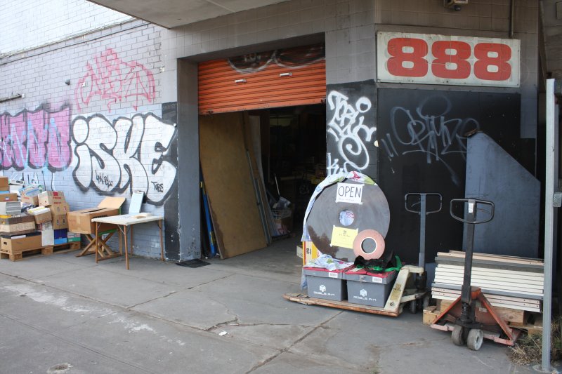
We have yet to find a suitable/affordable alternate space so ... "OPEN DOOR DAYS"
The old fruit shop at 888 Woodville Road, VILLAWOOD, will be open for anyone who cares to come and take anything away and help preserve our computing heritage.
Hours: Sat 28th/Sun29th 9am to 9pm, then Monday-Friday 10am to 10pm, repeat the next week.
Off-street parking, easiest access is from south (Hume Hwy), see Google Maps.
Bring your Car, Van or Ute and enough muscle to help empty our shed.
Please tell your friends and/or work colleagues. ACMS - Australian Computer Museum Society
I went on Tues 31st July, Wed 1st, Fri 3rd, Sat 4th, Tue 7th and Fri 10th Aug. Filled my car each time, plus took the trailer three times for a couple of large items and some metal shelving. Of course every day trip there implies considerable time at home dealing with the items brought home. Sometimes just packing them away, sometimes doing urgent remediation (urethane foam, urrgh.) Then there are multiple other items that could involve major restoration endevours — if I do undertake them. Bearing in mind that ideally I'm merely providing temporary storage space for this gear, and eventually it will go back to the ACMS. Otoh, their future is uncertain. Potentially this could be more permanent, and some or all of it never leaves here.
If you are able to help the ACMS preserve Australian computing history, by donating artefacts, money, or helping them find a suitable public display venue, here are their details:
 The Australian Computer Museum Society
web: https://www.acms.org.au/
email: acms@acms.org.au
post: ACMS Inc
PO Box 4005
Homebush NSW, 2140
Motto: Control-Alt-Preserve
There's an eevblog forum discussion here.
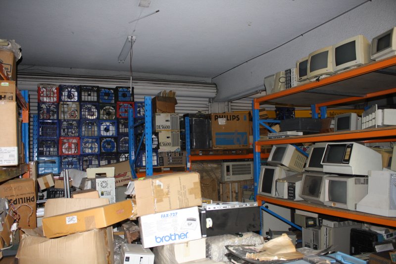
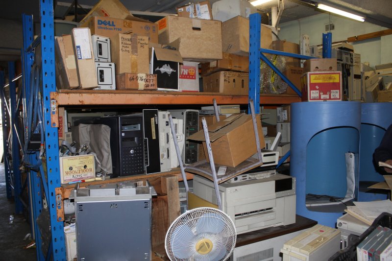
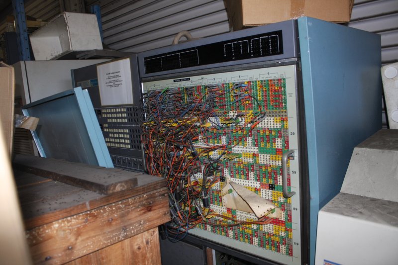
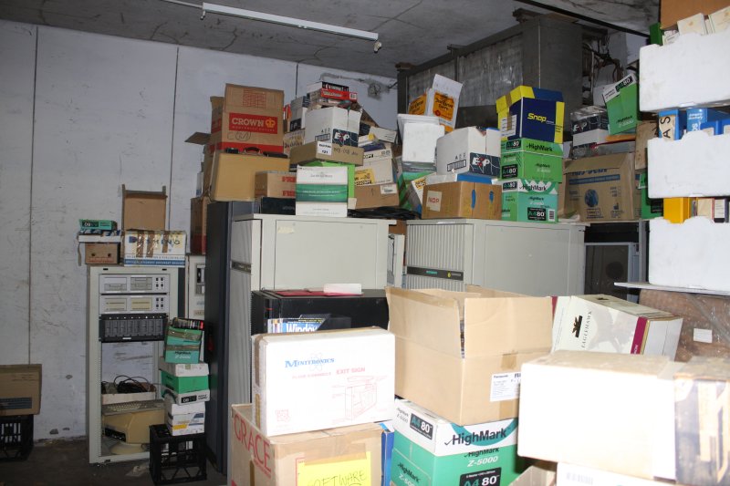
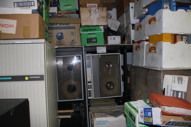
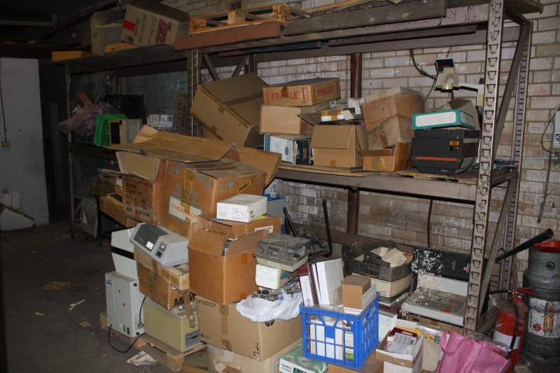
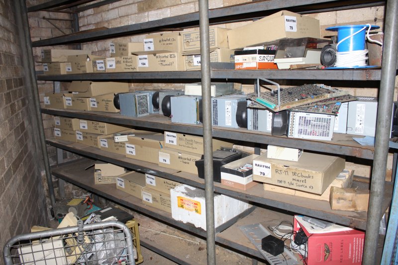
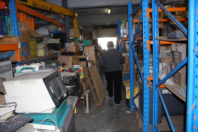
Some photos of the doomed warehouse of historic computing treasures:
 |
 |
 |
 |
 |
 |
 |
 |
 |
 |
 |
 |
 |
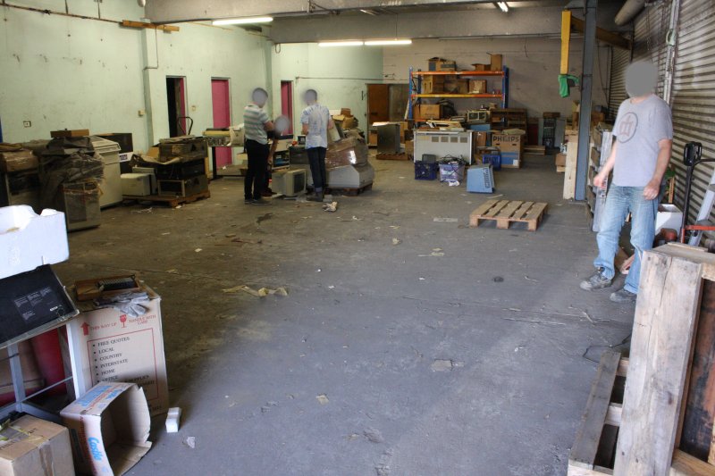 |
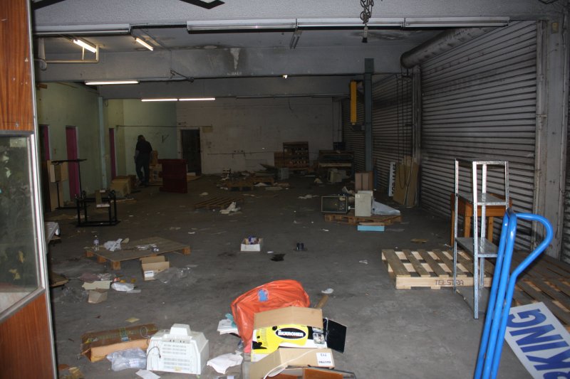
It was difficult to get photos that represented the items well, since most of the really interesting things were buried under boxes. The last pic is the main room on the Final Friday, nearly empty. In the end everything was removed, except a pile of unwanted old CRT monitors in a small back room.
 |
 |
 |
 |
 |
 |
 |
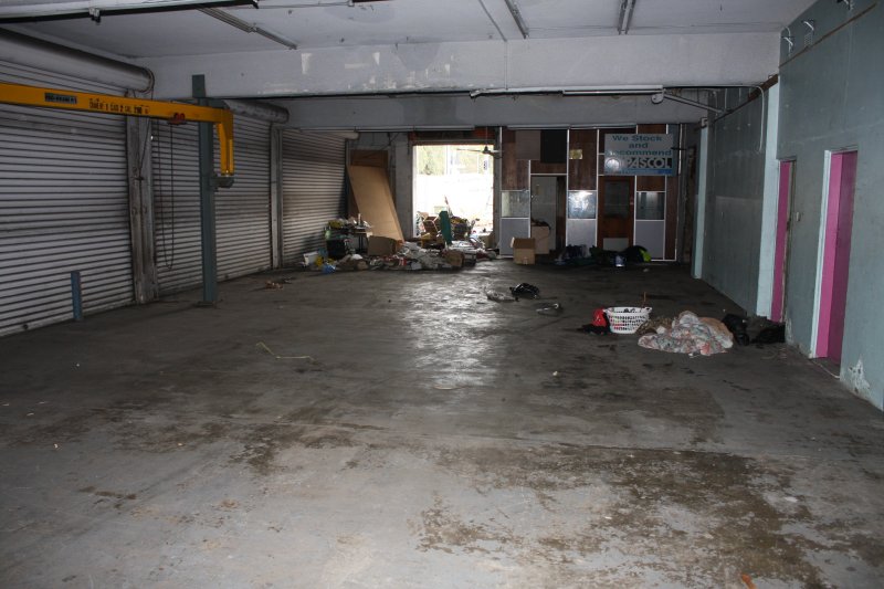
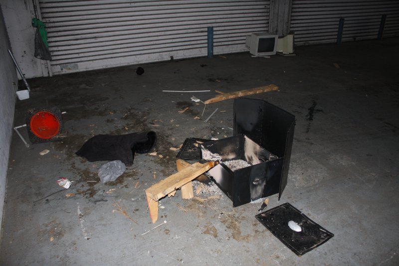
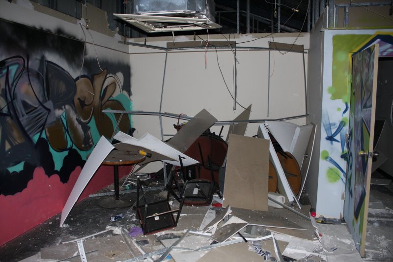
After the ACMS vacated, the building began the slide into chaos typical of any structure inhabited by those poor souls lacking homes and/or sanity.
The ACMS warehouse dispersal took two weeks of fascinating activity. Highly enjoyable. But there were a few frustrating elements. One was frustration with myself — a classic 'oh wheeeere did I put that?' stuffup. Remember that heavy duty moving dolly I'd made in March for the UPS move, with a ramp that linked to my trailer? In July I finally painted the metalwork, just a couple of weeks before the ACMS thing came up. So when I wanted to take my trailer to the warehouse to pick up a big and heavy old IBM 026 card punch (2nd visit, and expecting to have to get it into the trailer by myself), I thought the ramp and dolly would be perfect for that.
Hmmm... except that when I painted the metalwork, I'd taken the mounting points off the trailer to paint them too. And hadn't put them back on when I assembled the painted dolly and ramp. I had the bolts on my desk; where had I put the actual mounts?
Despite determined searching, I didn't find them until too late to be of any use in the ACMS move. I knew I'd left them somewhere obvious, in plain sight, because I may need them soon. But where?
 |
 |
Ha ha sob... I think I must be getting Alzheimers.
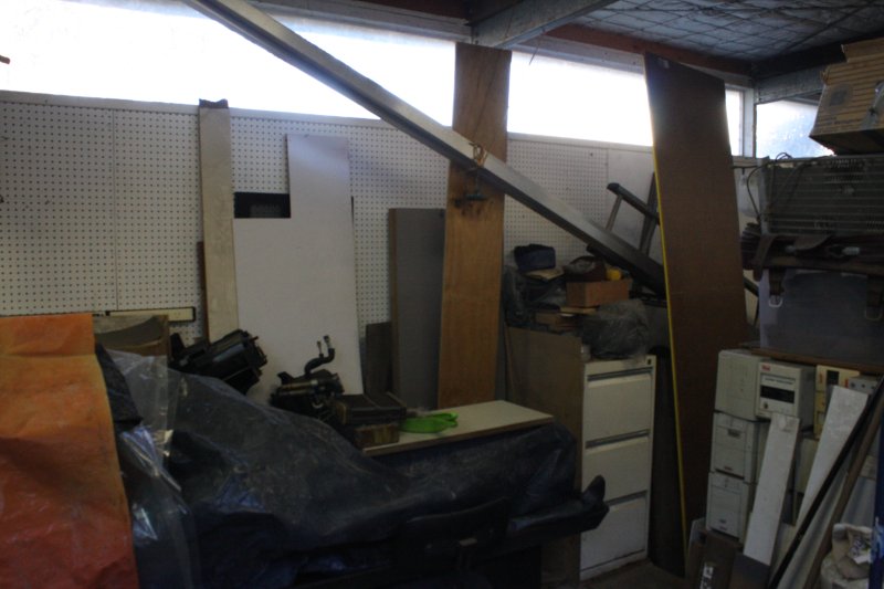
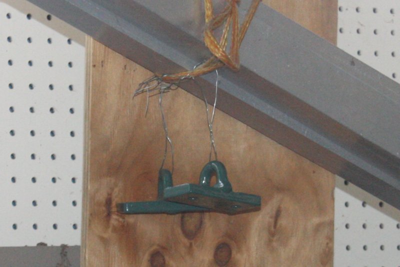
My unfinished 'forge shed' is a mess of piled stuff. After painting the dolly parts, I'd just shifted the trailer mounts (still on wire loops) somewhere out of the way. Which turned out to be in a spot of shadow next to a bright window. Highly effective camoflage.
Other frustrations were typical of any collection of old tech gear, though a bit extreme.
- Missing cables. Nothing ever, ever still has the required special cables and unobtainium connectors. In this instance at ACMS it's worse than usual since they've had a few previous moves. But even worse, at some point thieves were getting into this warehouse and taking cables to sell for copper. Actually cutting cables off, if they couldn't be unplugged.
- Item groupings completely lost. Everything had been churned, so things that should have been together, were not. Everything scattered randomly. Manuals separated from gear, essential accessories lost, and so on.
- Really special, precious and rare items, mixed in among mounds of worthless crap. Piles of ubiquitous tower PC cases and monitors, with buried under and among them, historic gems like an Olivetti Programma 101 (first ever desktop programmable calculator.)
HP 9830A Restoration
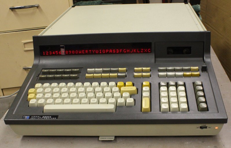
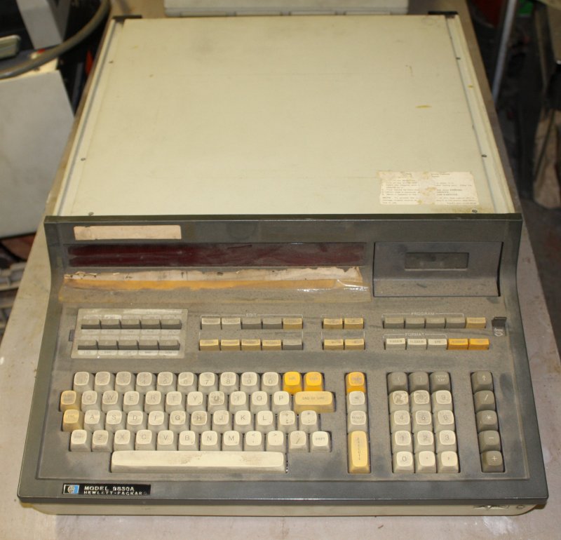
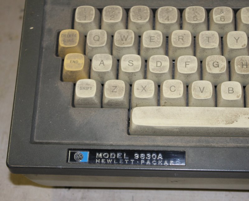
For me, the best treasure find was a pair of Hewlett Packard 9830A desktop computers.
 |
 |
 |
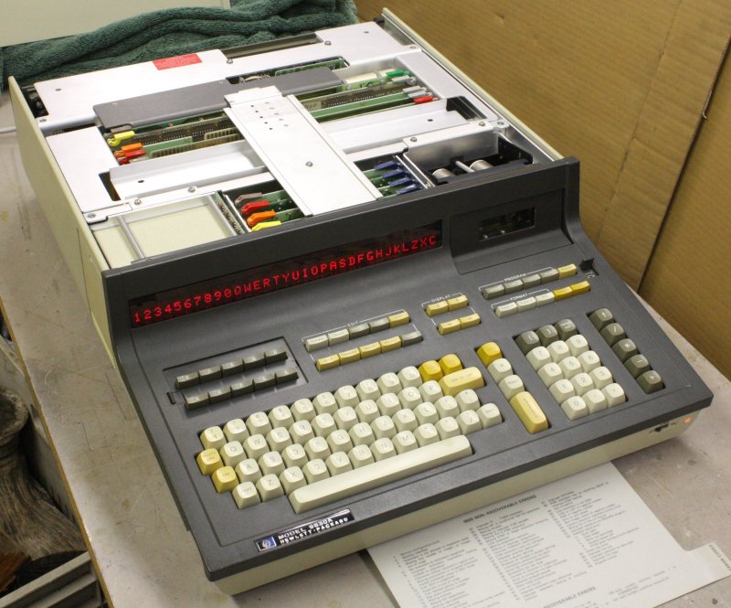 |
One was very clean, works, and came with a box of manuals and the printer. Also miraculously, the cable for the printer, because it was hidden in the box of manuals. (That box I found outside in the carpark, in the 'to be tossed out' pile.) However the molded keyboard face has some damage — broken-off internal mounting posts, and a big chunk cracked off an external edge.
The other unit was extremely filthy, with severe grime and multiple sticky tape adhesions. Also it's non-functional.
Some online information about the HP 9830A:
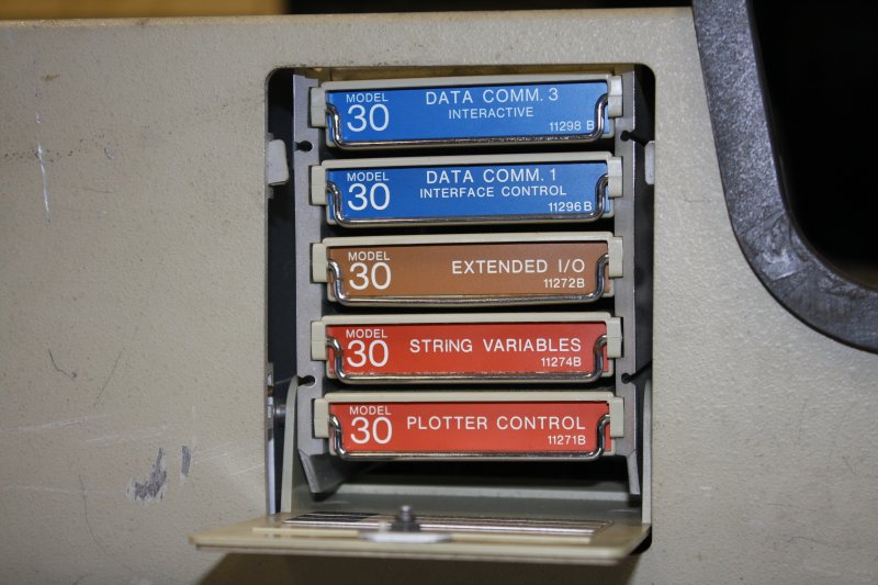
I find these machines exciting because they are from the glory days of Hewlett Packard before HP went corporate-psycho and then were greatly diminished by that Fiorina twat. The HP desktop machines are a landmark of the very early years of portable computing, before microprocessors were developed. There is no CPU on a chip in these, it's all relatively small scale TTL and MOS integrated circuits. The 'processor' in these is a set of circuit boards.
Thankfully there's no trace of octal notation in the user interface. I loathe octal. This helps me avoid the 'antique computers collecting mania' — amost all early computers used octal notation. Long live 0xHex!
What I do collect is HP test equipment from those years (to actually use in my lab, not just display), and a lot of it is remote controllable via HP-IB (IEEE-488) interface. With all the original manuals and code examples referring to machines like the 9830A. So for years I've been pining to have one of these, for completeness.
Another point is that supposedly most of what I do is intended to be in furtherance of a primary project; what the vacuum chamber system is for. With the chaotic mix of stuff I work on, there often may not seem to be any connection with that. But there often is, just not so obvious. (And sometimes I'm admittedly getting sidetracked.) Anyway, antique computers are definitely a sidetrack. Especially now, when I should be concentrating on other things (see project dependency tree mentioned at top.)
There are of course multiple other issues with both units, and restoration is going to be a lengthy process, in spare moments. See NobLog 20180803 HP 9830A Explorations, and the eevblog forum thread in Vintage Computing.
For this story, the main point is it took me another two weeks before the 9830A'a and most other things from ACMS were stabilized enough to clear out of my workshop and into safe storage spaces. While they were in the workshop I couldn't do anything else there. Welding and grinding are not compatible with precious computer hardware.
Meanwhile...
 |
 |
 |
 |
 |
 |
 |
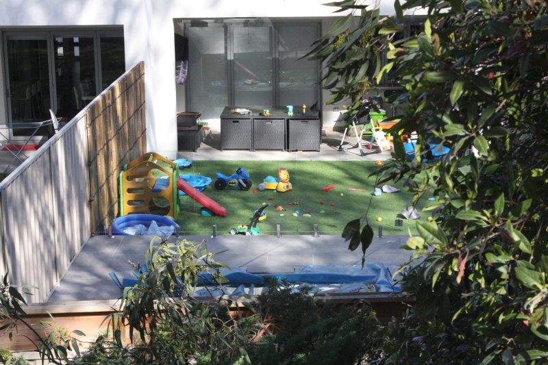
The usual random interrupts. 1 & 2, A Swoothing subterranean afternoon with friends, followed a couple of days later (3 & 4) by a most agravating morning. A recently new neighbor diagonally down the back is the type who likes plastic astroturf rather than messy living grass. And will use an incredibly noisy electric leaf blower to remove any actual plant matter in the form of tree leaves that blemish his pristine plastic desert. I wonder what kind of people his small kids will grow into, having been raised on astroturf? Anyway, he also installed a swimming pool, right next to the fence, adjacent two properties with several splendid large gum trees. One (in my yard) is huge, and slightly overhangs his fence by about a meter. He gets very upset about a few leaves on his plastic lawn and pool. His idea of a solution: cut the tree right back. And he expects this to be right back, much further than the fence line.
I told him a) not going to happen, I like the tree, and b) even if the tree was cut back, it won't make any significant difference to the amount of leaves on his astroturf, since surprise surprise, leaves blow in the wind, not just falling straight down. And there are many trees around here (thank god.) Overall I'm not happy with this guy. He was the landlord of the old house there previously and allowed tennants to keep insufferably noisy barking dogs. Then he had a massive rock-hammer excavator there for many months, digging his new house basement and the pool. His new building (a duplex) features two huge halogen floodlights high up on the rear wall, that shine into my yard at night when running.
Then the morning of Aug 7th, just as I was about to go out to do something important that I really didn't want to put off, some guys show up. A huge Tongan boss, his pretty big Tongan sidekick, an Eritrean and a Lebanese assistants. They are tree loppers, say my neighbor has hired them to lop my tree at the boundary line. And they need access from my side to do it.
WTF? Add 'insulting pushyness and lack of communication' to my neighbor's unpleasant traits.
I consider just telling then to piss off, no they can't come on my property. Really I'm not obliged to allow this. But, he does have the legal right to cut the tree at the boundary. He could do it with a lift platform or crane from his side, but there's no vehicle access to his back yard. (Because he built a duplex, close up to both side boundaries.)
I'm far too nice sometimes. Also the boss guy suggests he'll also cut down an old dead tree on my property — that is actually a problem, as it's too big and high for me to do easily. So I said OK. This was a huge mistake.
There followed several hours of the most unbelievable f*ckery. They'd obviously been paid by my neighbor to cut the tree back as far as they could get away with. I certainly wasn't going to leave them to it, so had to stay. It was a constant battle trying to stop them over doing it, and not always successful. They cut back lower branches far more than I wanted. Then they found they couldn't get to the higher branches. Oh big surprise! Had to call in another guy who had tree climbing gear. He too cut back far more than I permitted; actually pretending he couldn't hear shouts to stop. The whole thing was a perfect example of how certain nationalities get bad reputations for being pushy lying arseholes. Except the Eritrean, he was cool.
So, having done a lot of damage to my lovely tree, they then started to prepare to deal with the large dead tree. The tree climber guy had left when the boss refused to pay him extra for this added job. They didn't have their own ropes or ladder, so at first I lent them mine. Then, as I watched what these clowns proposed to do, I realised they had no idea at all, and this was getting very unsafe. Not to mention risking damage to my good rope, ladder, the metal fence and maybe another neighbor's rear garage. I asked the Eritrean about their accident insurance, and it turned out they didn't have any.
Finally I did what I should have done when they first showed up. Told them to get out.
Sigh. I'd long ago decided that neighbor is a shithead. Why did I try to cooperate with his rudely sprung-surprise plan? I will never learn, apparently. In hindsight I suspect their farce with the dead tree may have been intended to get them evicted, since that meant they didn't have to cut up the downed branches from the live tree. Or maybe they really were just idiots.
Anyway, finally mid afternoon I could leave, as I'd intended to mid morning. Later it took me a lot of trouble to retrieve my two ropes from that tree, since the clowns had managed to get them both slip-knotted around branches far up out of reach. A metal hook on a long pole worked to slide the slip knots down into reach, thankfully.
Half the next day was cleaning up their mess, moving and cutting up the branches. I'd intended from the start to keep them, for firewood.
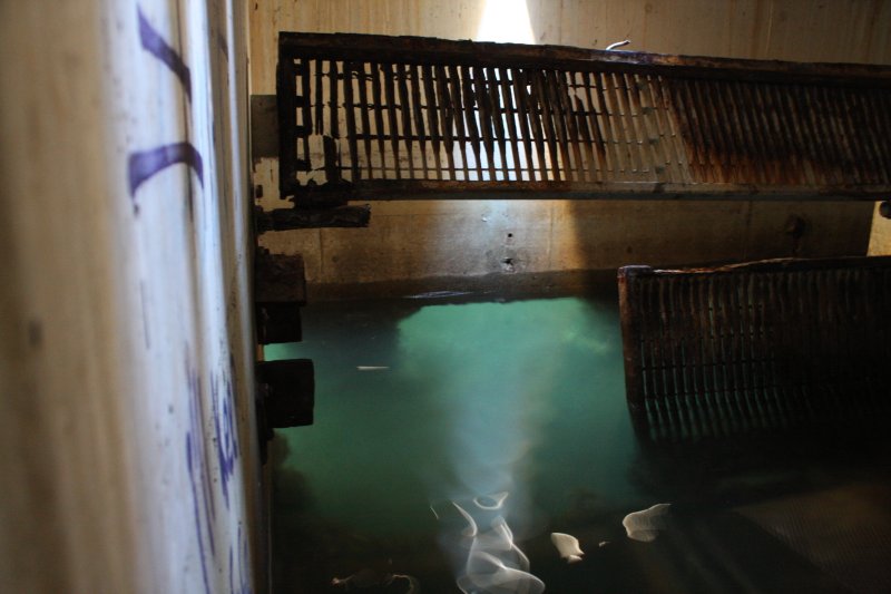
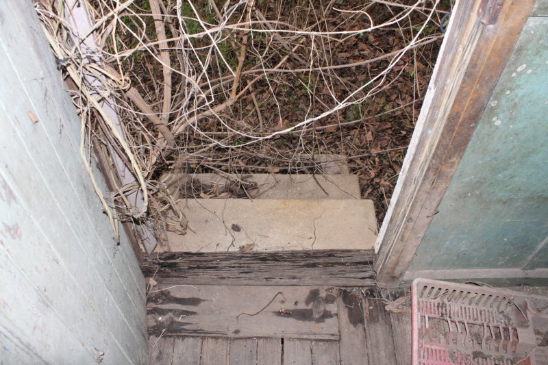
The final three pics are from other trips to abandonments. Such places are always interesting, in their demonstration of the power of entropy. Pic 5 is particulary poignant. I'm not going to say what or where this is exactly, but it's a relic of a major Australian national technical project built in the early 1960s. The entire system cost nearly seven million pounds at the time. Remnants like this now serve as nests for rats.
Gunked
 |
 |
 |
 |
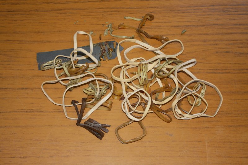 |
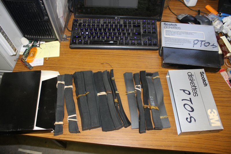
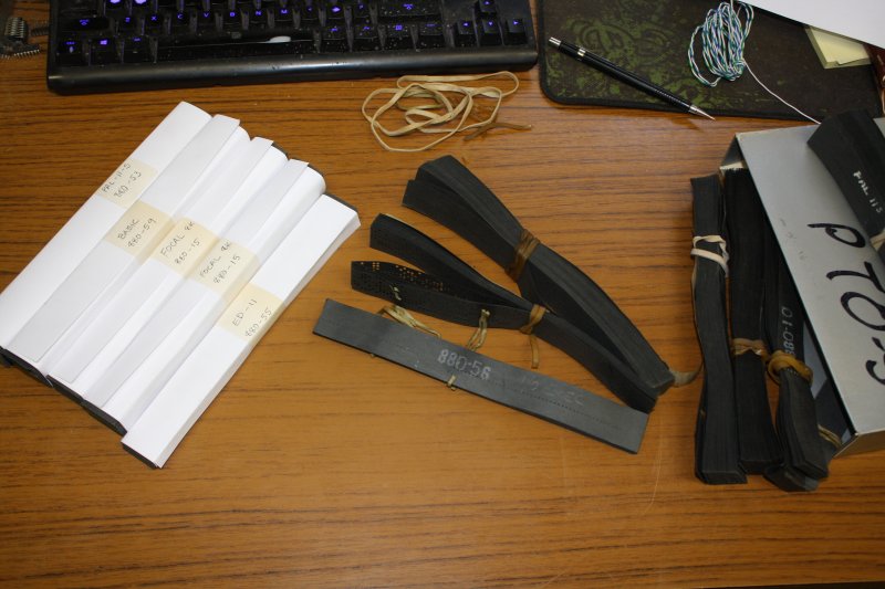
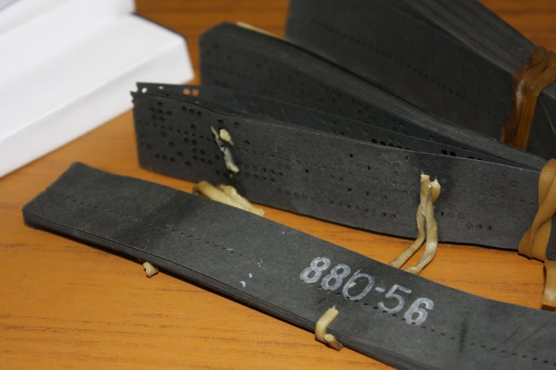
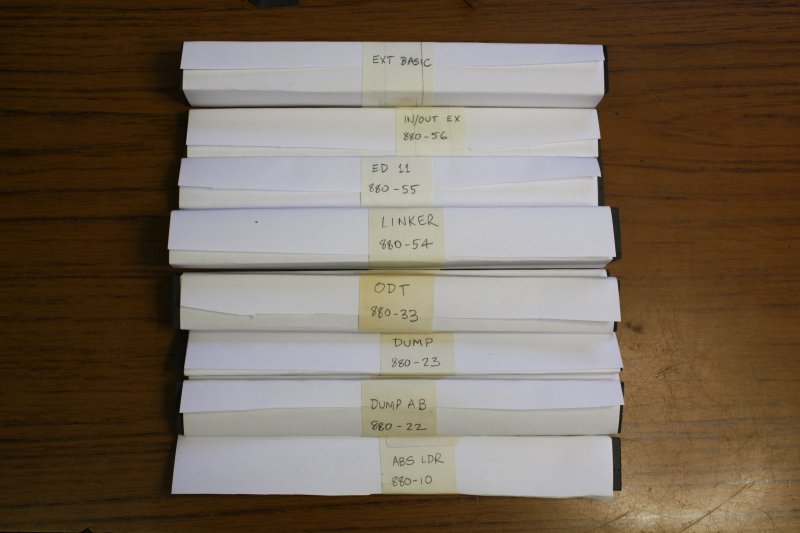
Going through the ACMS boxes, I'd found two old 8" floppy disk boxes with a sticky surprise. They contained old software on punched paper tape, in the fan-fold form. Which by chance happens to fit these boxes well. Someone had carefully packed them away, with rubber bands around the tapes. Oh oh...
You know not to put floppy disks near magnets? Well rubber bands are the equivalent enemies to paper tape. In time the rubber turns into sticky gunk. Never ever use rubber bands for any kind of long term storage. There went a couple more hours.
These are for the Heathkit H11, 1978-82. Compatible with the DEC PDP-11.
Once I get a tape reader going, I'll read these tapes and post the files.
Back to it, finally
 Where was I?
Oh right, the table construction. During the last sidetracked week, I'd found an Australian maker of sprockets (Finer PT), with a distributor IBS Industrial Bearing Supplies near me, in Padstow.
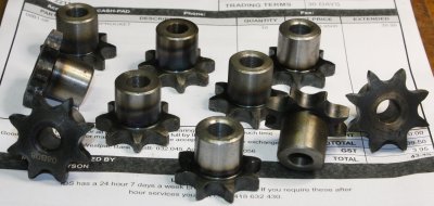
I'd ordered some, they arrived next working day. On Monday 20180903, just over a month since the ACMS lightning went ZOT! on this project.
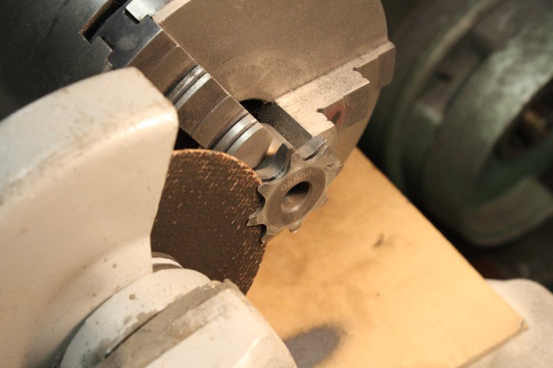
They are PN 08B1-08. Problem is those were the closest they had to what I want, but the teeth are too thick for the 410 chain. I bought them knowing I'd have to machine them down to fit. And that the teeth are surface hardened, so 'machining' won't work. Ha ha... which just means grinding is the only way.
 |
 |
 |
 |
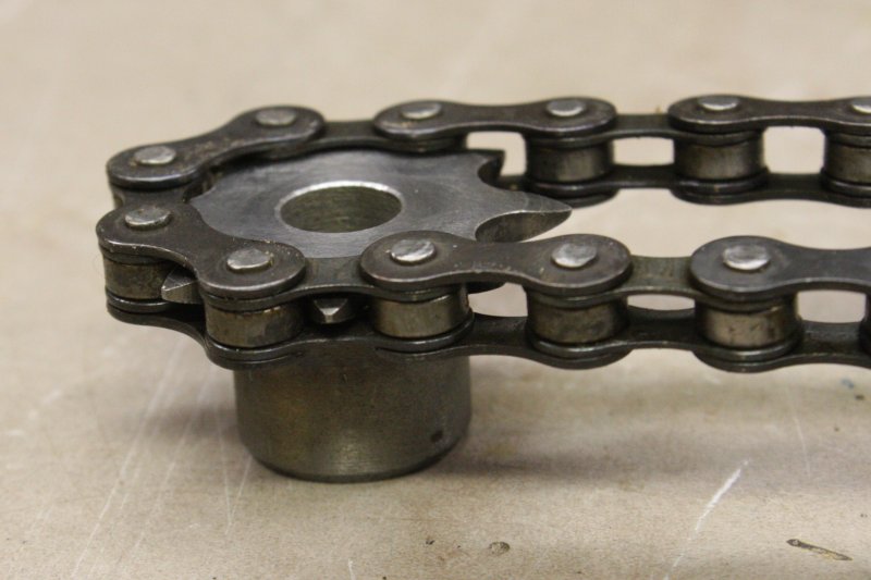 |
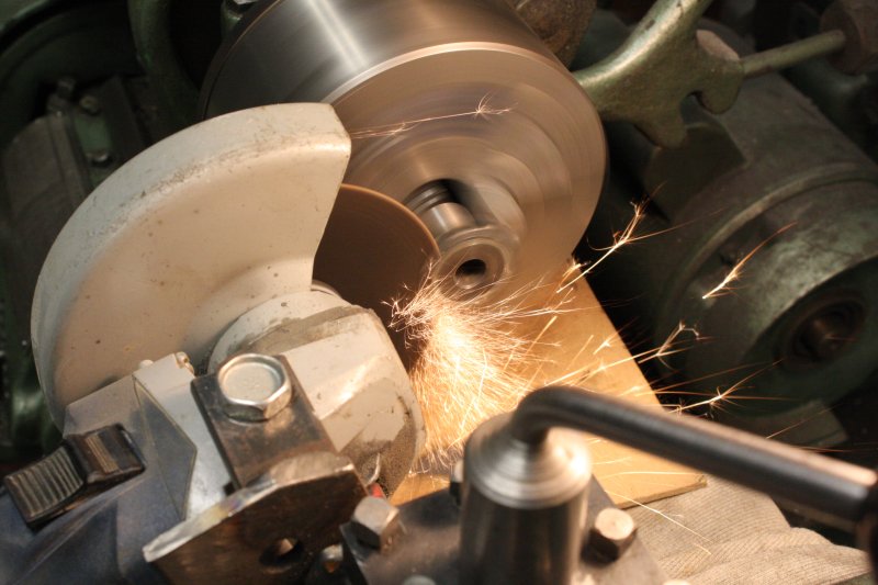
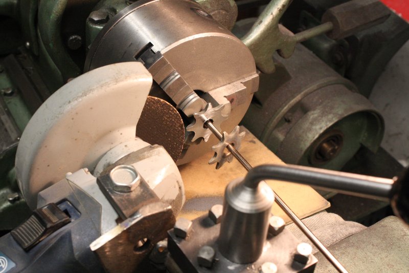
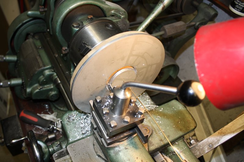
It worked. As with many a 'first attempt' I didn't get the three of them exactly the same. With an angle grinder mounted to the lathe tool post I started with a thin cutting disk, which went through the sprockets surprisingly fast. In pic 1 the grinder disk rotates clockwise, and the lathe spindle in reverse (also clockwise) so the contact point had opposing motions. The grinder spins a lot faster, hence the downward sparks spray. Cloth and board protecting all the lathe sliding surfaces from the grit.
First one I left a bit of a lip, but decided for the next two to not bother with that. The bevel on the teeth tips was done with the face of a solid grinding disk. And on the 2nd sprocket I forgot to lock the lathe saddle while grinding the bevel with the cross slide. I was wondering "why is it responding so sloppily?... Oh, oops." The grinder vibration was making the saddle drift. So that sprocket's taper is a bit oddly shaped.
But... I still am not quite sure about the mechanics of the variable height part of this table. I won't bore you with the multiple half-arsed doodles of possible arrangements. Still not happy with any of them. I think I'll leave it to my subconscious elves a bit longer.
In the meantime, what about that pin wrench idea? That will work. The old motor has been sitting there with that large shaft nut taunting me, for about six weeks. Grrr... today is the day it's coming off.
 |
 |
 |
 |
 |
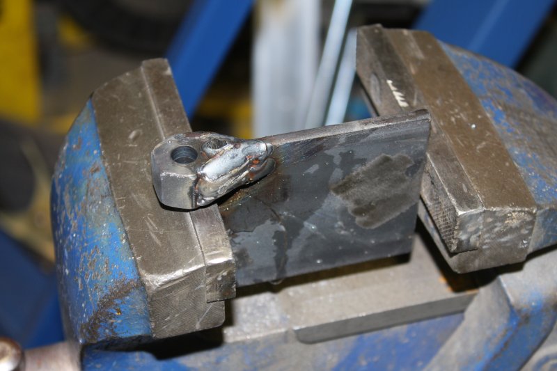
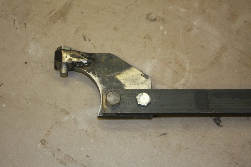
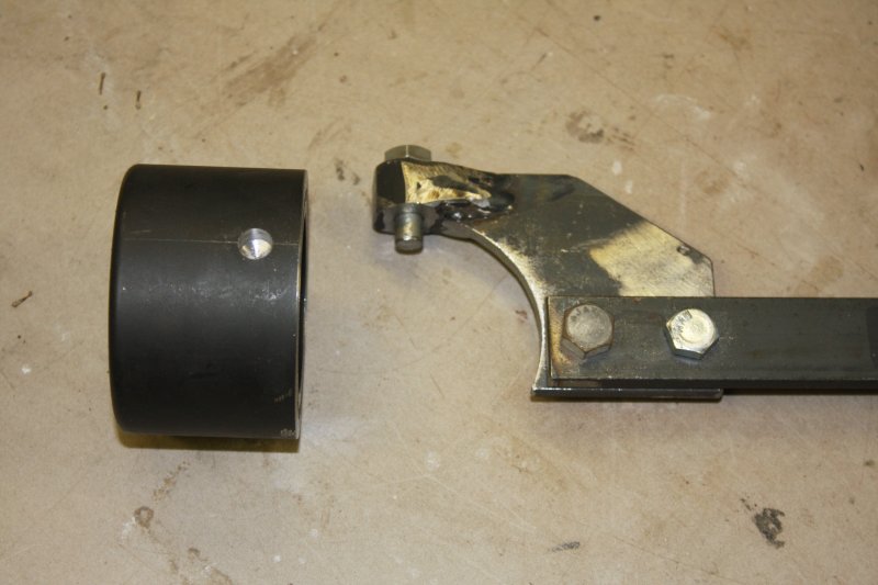
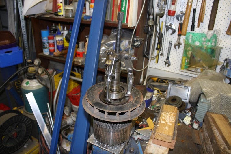
Easy to make. Wish I'd thought of this first.
 |
 |
 |
 |
 |
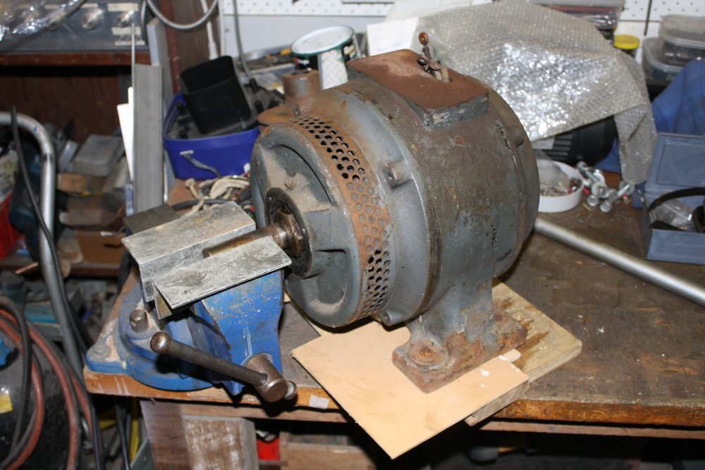
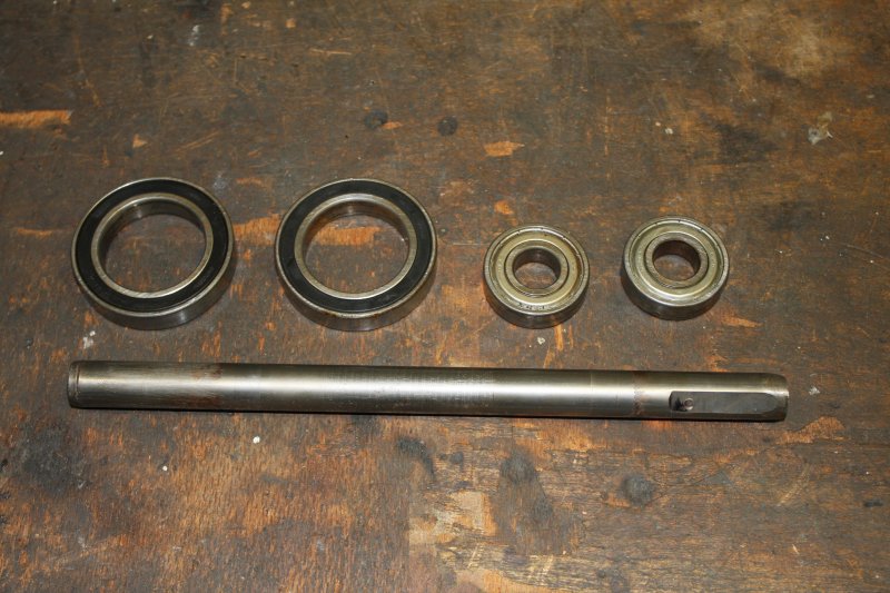
Success! Then my bearing puller was only juuust long enough to get the bearing off the shaft.
The centrifugal air fan is rivetted to a flange on the motor shaft, and the rivets are loose. Bet that made an interesting noise when running! Anyway, they'll be easy to fix.
Next stage, sandblasting. But that requires the other workshop be finished, with the compressor and sandblaster cabinet set up. So the motor gets put aside for now.
Back to the table construction now? Well...
 The elves have been doing pretty well. They've put forward a proposal that seems feasible.
Probably.
That's the trouble with 'first time' stuff that is any more than slightly complicated. There's a fair chance of hitting an unforseen problem. In the worst case this can mean scrapping the work so far and doing it differently.
So what I like about the current Elves' Offering, is that it minimizes the amount of material committed. All the complicated bits will be in that one horizontal section, which doesn't have to be welded to anything else until after it works (or not.) Also the moving parts are not going to be messed up by building them into this. They can be re-used if I have to change anything.
But still, I dithered a little. Here there's not just the structure, but the sequence of machining to get right. Thinks...
Meanwhile, again...
 |
 |
 |
 |
 |
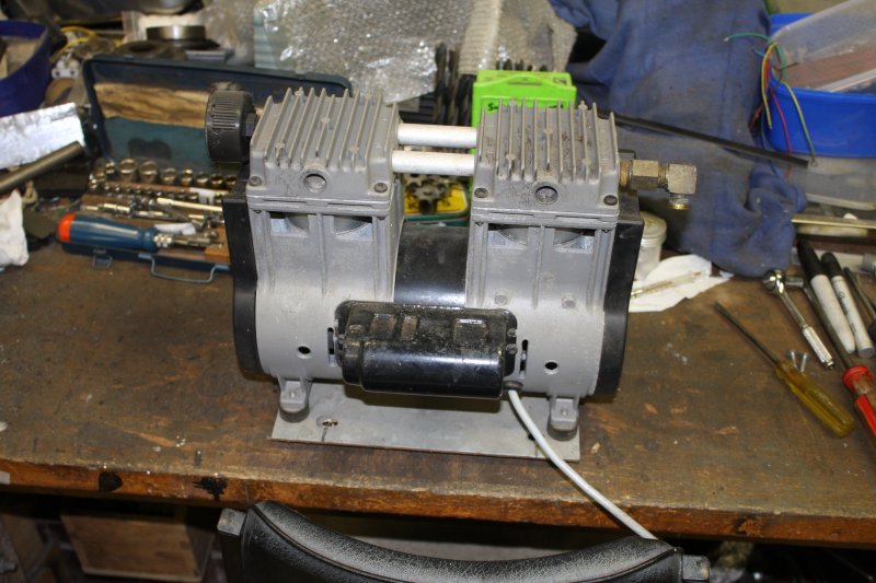
A quick disassembly, of a small air compressor I'd found. Plugged it in, it spits sparks. Oh well... I was curious what was the problem? Turns out 'everything'. The piston seals wore out, a cracked piston head also leaked air, it must have run continuously and burned out a motor winding. Final pic is the only components worth keeping.
I'd been driving past the old ACMS building in Villawood now and then, waiting to see when demolition began. Partly to get some photos for closure, but mainly because I wanted to ask the demolition crew if I could salvage something particular from the building.
That storage space I'm adding to the Forge Shed needs a roller door. I'd rather not buy a new one because money. Also I'd like a good solid one, and I suspect new cheap ones would be super flimsy. I'd noticed the entrance roller door on the ACMS building was about the right size. A little oversize actually, but that's what angle grinders are for. I'd also have to do some fiddly work adding the slides back to the cut end, but that's OK.
 On Sunday 16th Sept I noticed demolition had begun. Gate is now locked, junk cleared out, machinery on site. From people I'd previously spoken with I knew an adjacent shop was familiar with the site owner. I asked them, was given a phone number, but better, told the demolition foreman would probably be helpful.
Far better to deal with the on-site guys directly. So I'd go talk to them on Monday.
Monday morning a friend contacted me, asked if I could help him with moving tomorrow. I arranged to be there at 11am Tuesday.
Monday afternoon I went to the 888 site. Met the foreman, who was happy to let me come and take the roller door. With conditions: wear hi-vis vest and boots, and also... it had to be done tomorrow morning, since this building would be coming down Tuesday after lunch.
Oh boy, close timing. I had to go to my mum's as usual on Monday afternoon to do her shopping. I'm unable to contact my friend about the schedule clash tomorrow. So just went to his place after dinner. Luckily he was home, and we got the moving done that evening. But it meant I didn't get to bed till nearly 2am. Set alarm for 5:30am, to be at the demolition site with car, trailer and tools at 7am when they start.
I'm going to use 'tired' as an excuse for what happened.
 |
 |
 |
 |
 |
 |
 |
There are no pics of the early stages because I was hurrying, and none of the screwup because I was hurrying to fix it and feeling embarrassed.
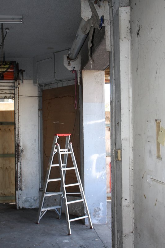
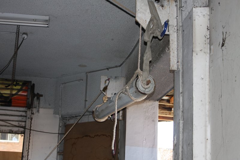
The plan was, secure the roller door in rolled-up form, release the internal spring tension, attach ropes to the ends via pulleys, secure rope ends to belay points, lift each end of the roller off the support brackets, lower to ground. Needless to say, it's very heavy. I wasn't sure I actually could lift the ends by myself, but had an offer of help from the demolition workers for that brief operation.
In practice, the roller had about 8 inches of length that couldn't be fully rolled up, due to the end hitting the door opening top. I wanted to get it fully rolled before tying it. So I started to take the vertical guides off first, thinking then the roller could clear the door and be rolled up.
With one guide off I thought wait, it's still under spring tension, if I just let it clear the frame it will roll up violently. So how much is the spring tension anyway?
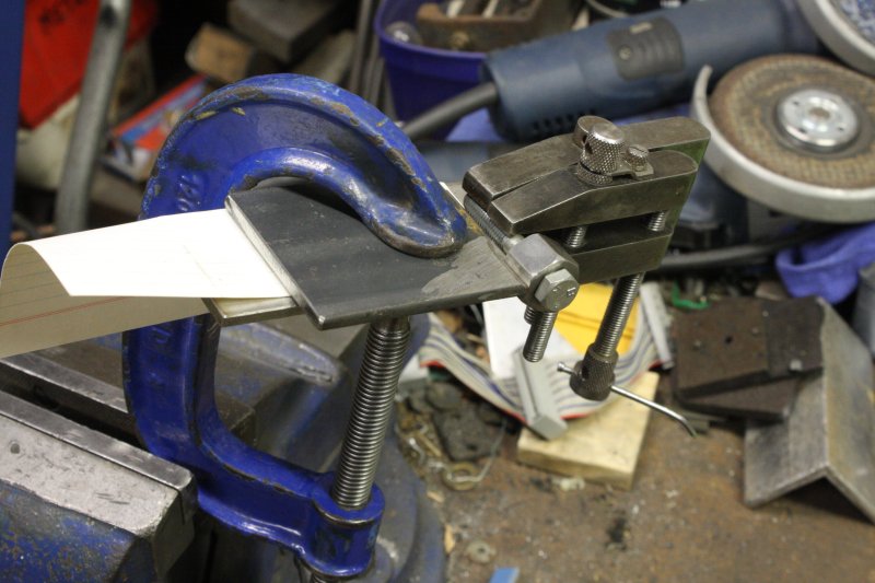
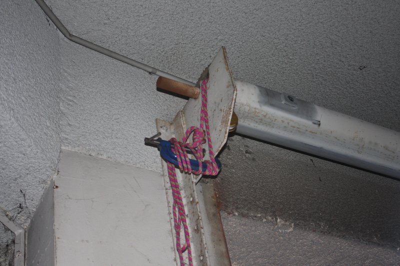
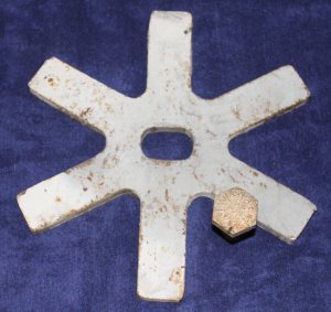 The tension on the roller inner spring is held by this 'asterix' on the shaft at one end. To stop it rotating a single large bolt is screwed into a nut welded to the support bracket. Up on the stepladder I hooked a crowbar claw end over one of the spikes, rested the crowbar shaft on the roller axle, and with that maybe 5 to 1 lever advantage found I could easily back off the tension. Then the bolt was finger-loose. With one hand holding the crowbar tension I unscrewed the bolt with the other hand.
This is probably how nuclear power plant operators walk into disasters. A series of small steps that each seems reasonable on its own.
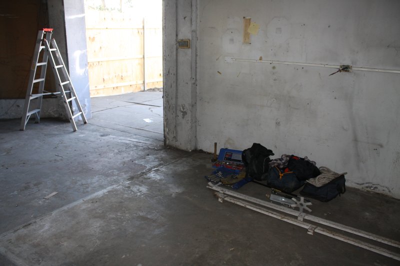
I tossed the bolt down to my toolbags. So then I'm holding the spring tension just with the crowbar. It wants to unwind several turns, but I can't do that under control because the crowbar end won't clear the ceiling.
Hmm... maybe I should think about this a bit more? Whoops, I'm up a ladder and the bolt is now on the ground. I can't put the bolt back, can't let go of the crowbar. Oh well, why don't I just let the shaft spin to unwind the spring, what can go wrong?
Ha. Well in hindsight it's obvious what could go wrong. But it wasn't at that (tired me) moment.
I rotated the crowbar so the claw hook let go of the asterix projection. I'd expect the asterix and shaft would spin for a moment, then everything would stop.
That's not what happened.
They spun alright! A lot of spring tension, converted into a clockwise momentum of the shaft and spring, quite a large mass. Once the spring was unwound, momentum carried it on winding up the other way, which meant it was applying a clockwise force to the roller door drum. That's the 'unroll down' direction for the roller door. Which I hadn't tied up yet, thinking nothing would make it unroll.
This all happened in a fraction of a second. Suddenly the roller door end was accelerating downwards. Adding more downwards force as the door extended vertically. For a brief moment it was thundering downwards, very very noisily. I'd barely had time to comprehend what was happening, and realise that there was no way I could stop it, before the end hit the ground.
Because I'd removed the slide rail on the other side, that side of the door was unconstrained. For one thing this made it go down a little faster, and secondly it was free to move sideways. That side hit the ground a bit before the other, and lots of the door's falling energy got converted to a sideways impulse.
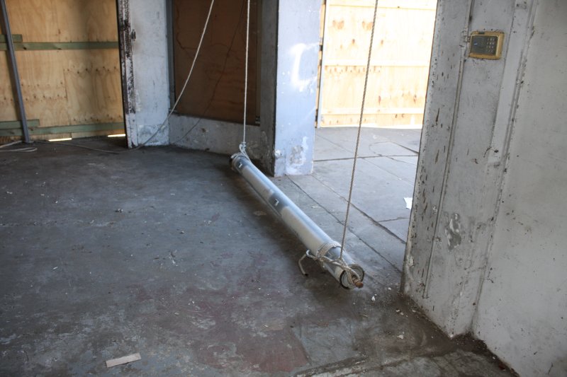
Roller doors are a series of interlocking slats slid together horizontally. They can unslide too! The sideways impulse resulted in several sections of the door sliding sideways, bottom-most section the most, higher sections progressively less so. The door ended up looking like a cartoon lightning bolt - a series of serrations.
Luckily I'd set the ladder and myself up out of the line of fall of the door. The demolition crew ran to the other side of the door, calling out to see if I was OK. Yes, I'm OK, but my pride is in pieces, thank you.
Oh well... the door doesn't seem to have any significant damage. So adapt, change of plan. The demolition foreman had been good about my goof, and let me continue. I followed the 'lighning bolt' hints, and slid the roller door apart into sections, starting from the bottom. Eventually leaving just the drum to lower down by itself.
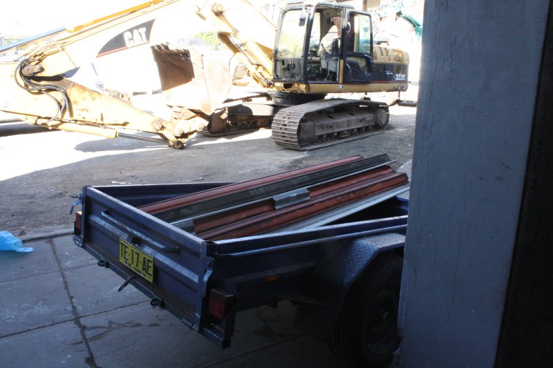
That's when I remembered to start taking photos. At least the drum by itself was light enough that I could lift one end at a time off the bracket and onto the supporting ropes by myself, so I didn't need to ask for assistance. The lowering part went well and by 9:30am I was all done and out of there.
Making it fit the opening in my new storage space extension, that will be another adventure.
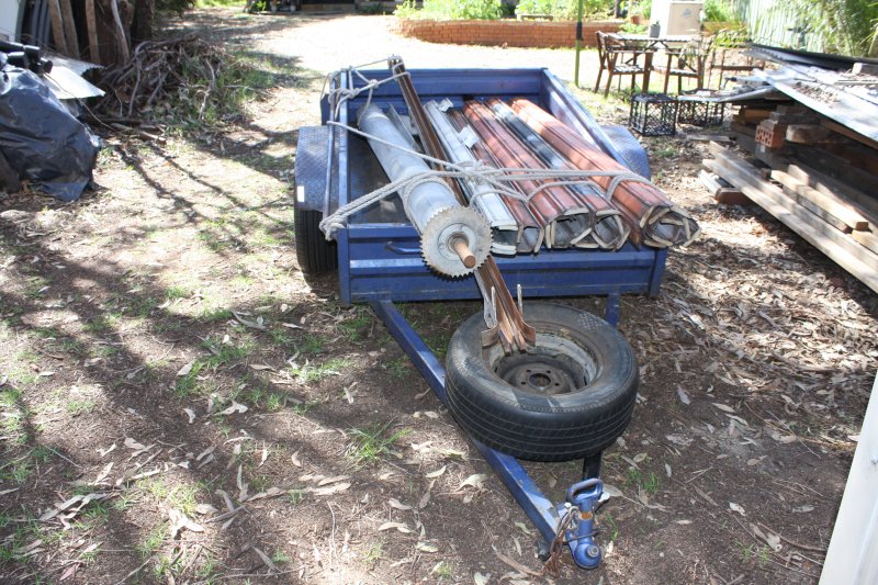
Oh, and there was one more small goof. After getting it home I checked the weather forecast. "No rain for several days", and it certainly didn't look like rain. So as I was busy with other diversions I just left it in the trailer per the last pic above, for a couple of days. Then woke at 4am in the morning to the sound of light rain. Bah. Get up, put on clothes and rainjacket, unload the roller door bits and store them under cover, put the trailer away under cover too. Go back to bed.
NOW can I start that table construction? This delay is getting ridiculous!
But wait... the workshop bench is piled up with accumulated junk, and there are still a couple of bits of historical computing gear sitting on the floor under covers. The table will involve welding and grinding. Maybe I should do some cleaning up first, and have a look at those bits of gear? But first... One of the times I'd been driving back from the ACMS building, I'd stopped to look at some consruction going on in a park. There's a pile of dumped rubbish. With a bucket full of big sodium lamps, used.
Ha ha, they have the  symbol (do not put in garbage) due to 35mg of mercury each.
So instead someone illegally dumped them.
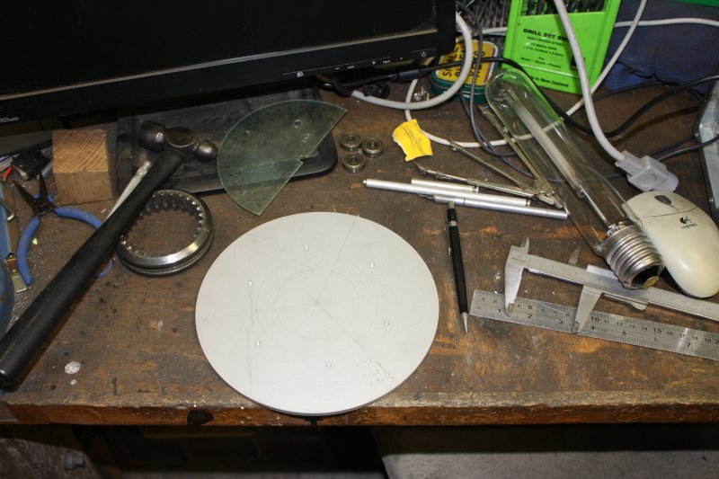
Hmm... Nice glass tubes, that suit a small background project. I grabbed them. I've been meaning for ages to get around to making a cutting tool for scoring neat lines around thin glass tubes. Here's a good test case.
 |
 |
 |
 |
 |
 |
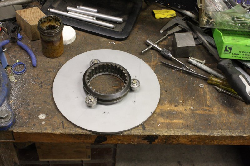 |
Not finished yet. It will have a glass cutter spring mounted on the disk, that can be rotated around the cyclinder. Luck was with this one — I found bearings that just happened to be very close fits in the groove of an old gearbox synchromesh gear. Now till I find a suitable bit of steel tube, it's back to...
 Not the table build, of course. First a long overdue workbench cleanup.
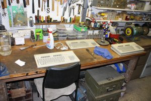
And cleaning some old HP keyboards. One of which is at last the right kind for my HP 80000 data generator.
RIP Gould's Book Arcade
 |
 |
 |
 |
 |
For all my adult life there has been a huge and very wonderful second hand bookstore on King St Newtown, called Gould's Book Arcade. It's been a landmark for all Sydney booklovers. A few hours digging through the perilously stacked book mounds in Gould's was always time enjoyably spent, and I've found many interesting volumes there over the years.
Now it's gone. There will be a new smaller store opening at 536 Kings St Newtown (opposite Alice St.) but I doubt it will have that 'vast chaotic collection' atmosphere. Google Gould's Book Arcade images for an idea of what it was like.
Those retro-computing 'quick' restorations, and lathe + motor rebuilds will be stories on their own.
The time it takes to write these articles is another diversion. They tend to become yet more unfinished projects — curently there are about 20 of the already posted ones that need extra work, and 35 started but not complete enough to post.
Stay tuned for our next gripping episode here, in "Will that darned table ever get built?"