 represents, or why
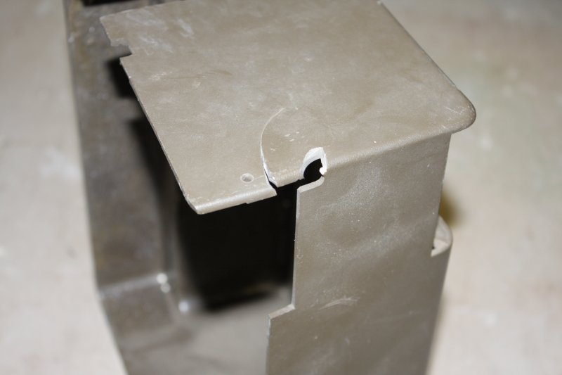
  has anything to do with cell phones.
20180922 TerraHertz http://everist.org NobLog home Updated 20181122
(Note! This one is posted in more than usually incomplete form, so friends can follow progress of the TM200 punch card reader restoration.)
As the early history of Informaton Processing fades into the mist, it becomes invisible to those who were born and grew up long after those days. Many young people don't know what the common 'save file' icon represents, or why has anything to do with cell phones.
But those disappearances are relatively recent shifts in tech-culture. I like to poke around a little further back in the trail of digital tech-memories. In the very early forms of data storage, long before we had removable magnetic media or later solid state stores. Before floppy disks, or even audio cassette tapes used to save data. What was used then?
Paper.
It's useful stuff. Not quite as durable as symbols carved in stone, or pressed into fired-clay tablets. But so much more convenient and versatile. Making paper in the traditional way wasn't easy, but what modern paper mass producton lacks in spirit and beauty, it more than makes up for in volume.
We've supposedly been using paper since the first century AD, unless you count papyrus, amate and vellum/parchment. And palimpsest, the medieval equivalent of white-out.
I said 'supposedly', because I rather suspect the people who built the Antikythera Mechanism sometime around 200 BC must have been using something like paper for a long while already, to achieve that level of engineering and astronomical expertise.
Paper became ubiquitous, in libraries, industry, courts, government and daily life. Used for everything; knowledge, laws, love poems, fireworks, kites and outhouse provisioning. As soon as we developed machines, paper was used with them too.
1725 First semi-automated industrial machine, using punched paper tape.
Previously cloth-making draw looms were capable of making patterns, but operation was entirely manual. Production of complex repeating patterns was very laborious and error-prone. In 1725 Basile Bouchon partially automated the process via a continuous loop of perforated paper. The hand-punched holes controlled the lifting of threads in the loom to define the cloth pattern.
1745 Jacques de Vaucanson in France created the world's first completely automated loom, using punch cards, drawing on the work of Basile Bouchon and Jean Falcon. However French weavers did not take up his innovations.
1751 Vaucanson invented the first industrial-size all-metal lathe with lead screw and slide saddle. 'Make ALL the things!' This development was crucial for creating precision machinery, without which paper control tapes and punches could not be mass produced or fully utilized.
1750—ish Towards Telegraphy.
The idea of transmitting information along wires via electricity arose in the latter half of the 18th century. But some concepts required for practical implementation were lacking.
1804 The Jacquard loom, using punched cards.
This was an evolution of the Bouchon loom. In 1804 Joseph Marie Jacquard invented a loom controlled by a series of punched cards linked together. Each card's holes defined a single row of the cloth design.
1820 Discovery of connection between electric current and magnetism.
On April 21, 1820 Danish Hans Christian Oersted discovered that electric current could deflect a magnetic needle. He experimented further and published his observations on July 21, 1820.
1823 Ampère's Law.
French physicist André Ampère developed a mathematical law to describe the magnetic forces between current carrying wires. Here's the original 1823 work in English (see Chapter 29.)
1831 Faraday
Michael Faraday demonstrated Electromagnetic Induction — that a changing magnetic field induces an electric current. Completing the symmetry of electromagnetic effects begun by Oersted a decade earlier.
1832 Morse
While on a voyage from France to New York in 1832, Samuel Morse learned of the discovery of electromagnetism, and conceived of a practical recording electric telegraph.
1834 Charles Babbage, punched cards and his Analytical Engine.
With his initial design Difference Engine halted by a dispute with his engineer, in 1834 Babbage developed a design for the first versatile computing engine. This machine came to be known as the Analytical Engine, and was programmable via punched cards, inspired by the Jacquard loom. Though never completed it pioneered many of the concepts required for modern digital computers.
1837 Telegraphy without paper.
The interactions of electricity and magnetism were understood well enough to develop various telegraphic systems using deflection of magnetic needles to indicate letters in sequence. By 1836-7 these were functional though clumsy, with the worst flaw being that messages were ephemeral unless a human operator transcribed them to paper (correctly.)
1837 Telegraphy with paper.
Meanwhile Samuel Morse had developed his Morse Code, that allowed sending the alphabet via a series of short and long current pulses. By 1837 Morse had developed a working one-wire system which produced a zig-zag line on a strip of ticker tape. The recorded wiggles could be decoded into letters and numbers via a table composed by Morse.
1844 First pompous telegraph transmission recorded on paper.

Click for the full tape. And yes this is a photoshop, since the only images I could find online were lo-res, cut up and messy.
That tape was produced by a Morse embosser. This widely referenced 'first demonstration' was on May 24, 1844, at the opening of the worlds first commercial telegraph line, of 40 miles from Baltimore to Washington.
As usual official history is sanitized. There was at least one known earlier telegraph message via this Morse-Vail long line system. That one on May 1, 1844 involved trolling passengers of a train; setting an amusing precedent. Of course many even earlier transmissions must have been conducted during initial development and testing. The "what hath God wrought?" demonstration was more of a PR exercise in front of members of Congress, than an actual first.
That system used marks on paper (and the spaces between) to record the dots, dashes and spacing of the morse code, transmitted as current flow though a single-wire cross-country cable. Note that this is where the term 'mark-space' originated, later used to describe the two levels of bit-serial protocols like RS232.
As you can see from the illustration, one problem was that the marks were faint, and could fade away to nothing.
There's also some question whether 'Morse Code' (as we know it now) and the 'Morse embosser' should even be attributed to Morse. His friend and partner Alfred Vail greatly simplified Morse's original codes, allowing easier translation and even 'sound reading.' Vail also apparently developed the idea of a stylus that lifted up from the tape, thus producing the 'dots and dashes' of Morse code, rather than a wiggling line.
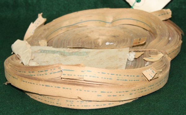 Other systems were developed to make clearer, more permanent dots and dashes on paper tape, such as this roll of tape using ink rather than an embossed mark.
Example, date unknown, from the Telstra Museum, Bankstown.
Others even printed characters.
Yet something more definite and permanent was needed. Something that would last as long as the paper. Something machine-readable.
Like... holes in the paper.
This concept had been around since 1725 — over 100 years. So really it was more a question of mechanising the punching and reading of holes, using electricity.
1867 Telegraphy with holes in paper.

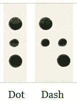
Apart from small sprocket holes for tape feed, there are only two rows of holes, and only three 'codes':
The sample tape shown (Telstra Museum, Bankstown) has some damage from being fed through a malfunctioning reader. Pins deformed edges of some holes.
 The machine readable Wheatstone tape allowed many advances. Lengthy message sequences could be preserved, for replay when needed.
More pics to come
  http://www.samhallas.co.uk/telhist1/telehist.htm
  http://www.samhallas.co.uk/telhist1/telehist2.htm
1873 Maxwell's Equations
1874 Baudot coding
Baudot tape had five rows of holes for the code, and a sixth row of smaller holes for feeding the tape through the reader. Baudots code, which you will remember was made to be easy to memorise, was later standardised as the International Telegraph Alphabet Number One.
1887 Heaviside condition, for distortion-free transmission lines
1902Murray improvement on Baudot coding
Of course machines like the card punches and card stack readers were vastly beyond the financial resources of a poor student (particularly poor in my case.) Also of no use to an individual anyway, lacking the giant mainframe they served. They were still pretty impressive bits of engineering, inducing a degree of awe in me at least.
At this time I had no access to any kind of computer, meaning there was no point even trying to obtain a paper tape reader or punch myself.
There was an interval there when I would have liked a tape reader/punch, but couldn't afford them. Then after a while floppy disks made paper tape obsolete for personal use.
So for years I'd been working with and around systems using holes in paper tape and cards to store data. Without ever owning any form of paper tape or punch card machines myself. Much later in my retirement, it would have been nice to acquire some examples of such gear. But aside from setting up a capability to recover data from old punch card decks and paper tape for historical reasons, there wasn't much point. Or anyway, not enough motivation to dedicate scarce funds to such ideas, over other more valued projects.
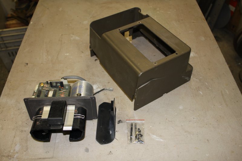
Then suddenly, via the ACMS unexpectedly losing their warehouse lease, I found myself holding a collection of items related to 'storing data via holes in paper', including:
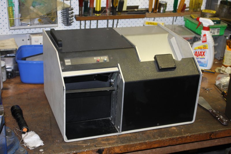
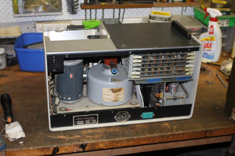
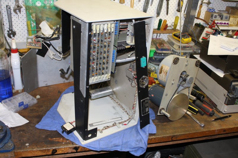
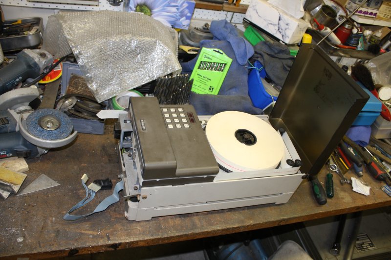
1. As received. Not toooo dusty. It's missing a card weight for the input stack.
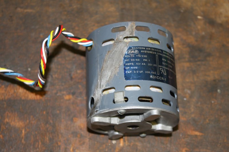
1. First look at the internals. The label on the fan housing says this unit was manufactured 4/19/77.
1 - 3. Disassembly begins. By now another less than exciting detail is apparent. This machine has been previously worked on by one of those people who lose screws, and then put remaining screws back in whatever order they seem to fit. An Ape.
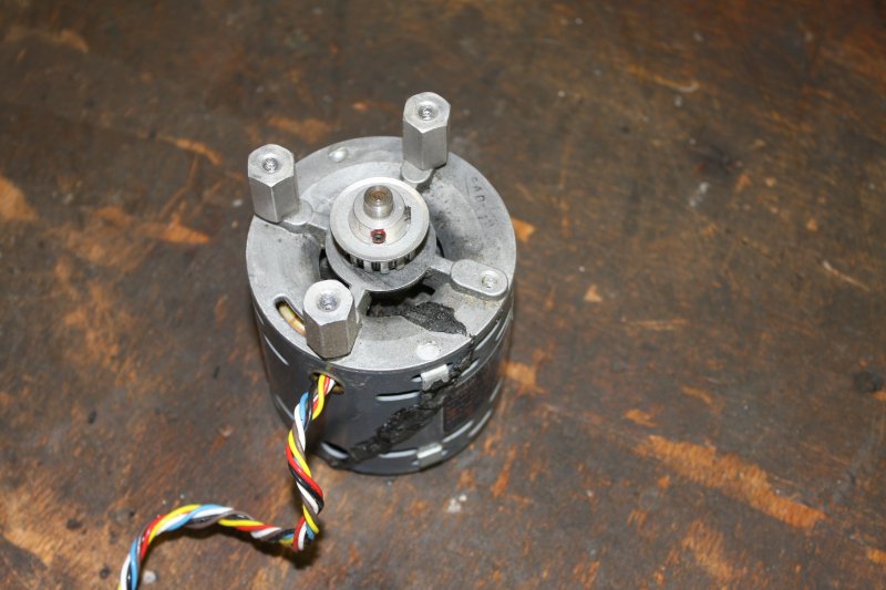
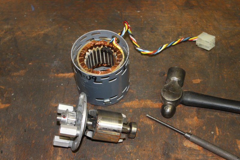
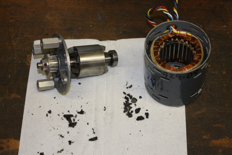
1 - 3. Disasembling and cleaning the motor. Not difficult, but requires care not to scratch the enamelled windings while scraping off the internal gunk. Curiously the rotor (bare steel) also has an area of surface rust, as though at some point water dripped in. That's not the only spot in the machine with mild rust stains. Was this exposed to weather sometime?
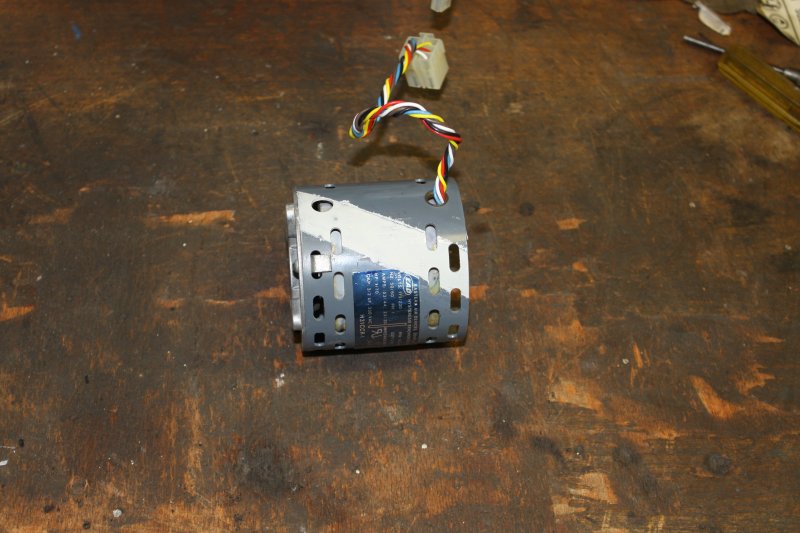
1. Now the motor has a racing stripe, ha ha.
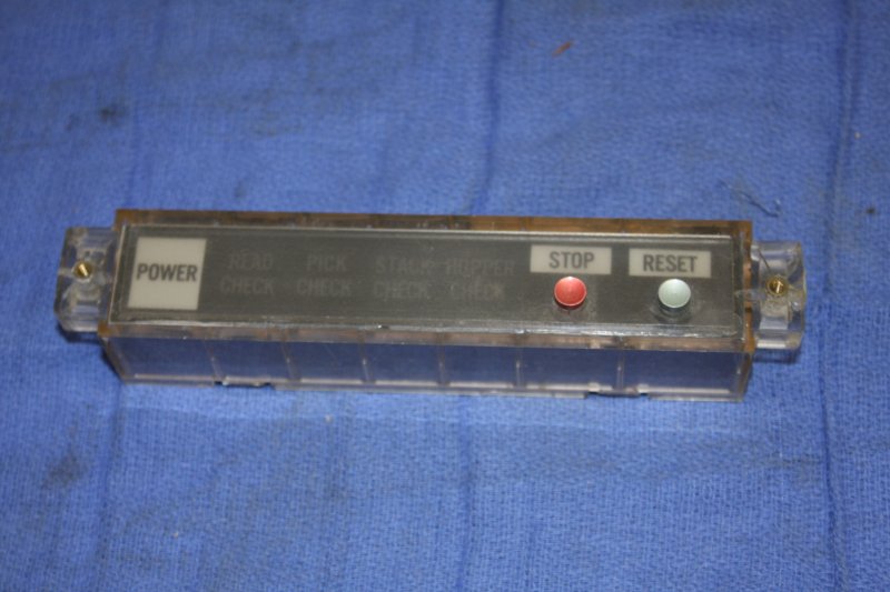
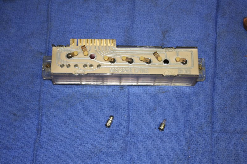
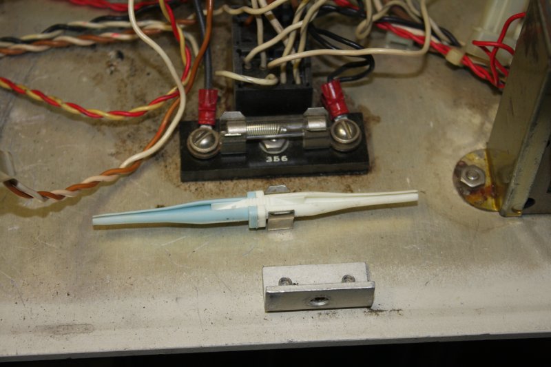
1. The rear of the status display. Of course it uses filament bulbs (CM 381) and of course a couple are dead. Anyway, these are available and cheap.
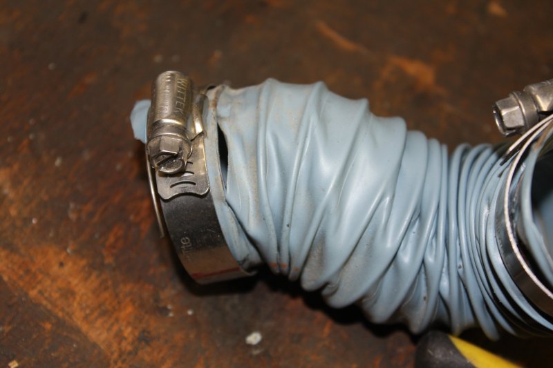
1. Suction side air hoses. Thankfully the central junction piece's plastic seems still robust. But the hoses... I think they were probably once a variety of Tygon, which is quite flexible. But it decays in time, to this stiff and tacky mess.
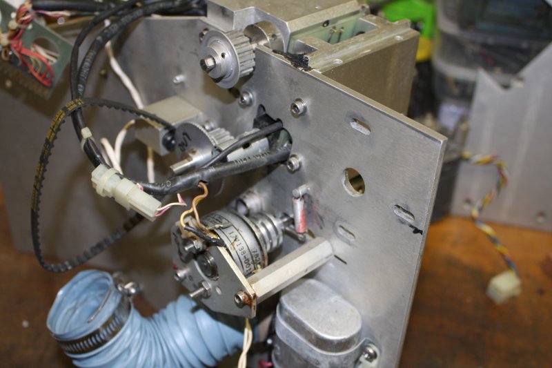
1. This thing is a rotating solenoid. It drives the card picker vacuum shoe. Thanks for making the grub screw line up with one of the two mounting posts, guys.
1. Well, that's the worst of the gunk accessible. Might as well get started.
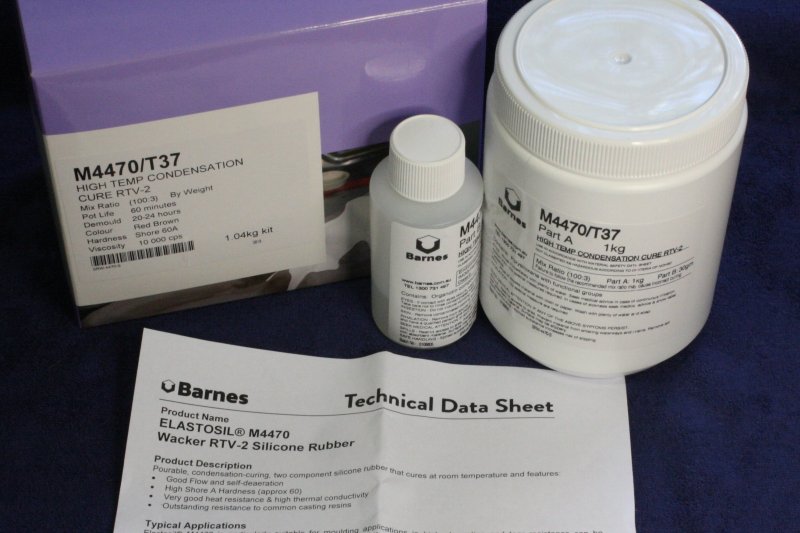
That and web searching turned up quite a few potential methods. The ideal would be to machine a mold, to allow forming a vulcanized rubber roller bonded to the original aluminium hubs. Much the same as Terrysrubberrollers apparently does. One problem with that is the learning curve of rubber chemistry, finding raw materials, and threading the needle of getting everything right to achieve a rubber with correct characteristics, and which won't rapidly turn to goo (again.)
Such knowledge tends to be hard to obtain, involving trade secrets, recipees known only to old hands, etc. Except...
One of my hobbies is Urban Exploration — basically wandering through any kind of place the public wouldn't normally see. Old mines, tunnels, abandoned factories and buildings, whatever. One sees some amazing things. Also some very sad things. A theme I notice, is that sometimes businesses for whatever reason, simply cease operations at a site and walk away. Then the site begins a long decline that may last decades, before the ruin is demolished and some new structure erected. That declining phase involves many factors: vandals, copper strippers, junkies, occupation by homeless, graphers, weather and water ingress, insects, mice, rats, birds and cats, plant growth, structural decay and collapse, fire, partial demolitions, and so on. Which makes for many interesting exploration and photographic opportunities.
All those forces of entropy are understandable, except one. I find the psychology of vandals inexplicable. On the one hand I'm quite convinced there's some kind of offical policy that all abandoned buildings have to be rendered uninhabitable, to prevent squatting becoming a common thing. Many sites I've seen appear to have been visited by some kind of paid wrecking crew that were given instructions to destroy all plumbing, wiring, glass and area enclosures. Which they did comprehensively, but without bothering to smash other things that someone who simply enjoyed smashing stuff would have.
Then of course there are simple vandals, who seem to have a deep hatred of anything reminiscent of 'civilization', and enjoy reducing all visible order to a state of maximum entropy. Not that they'd understand such concepts.
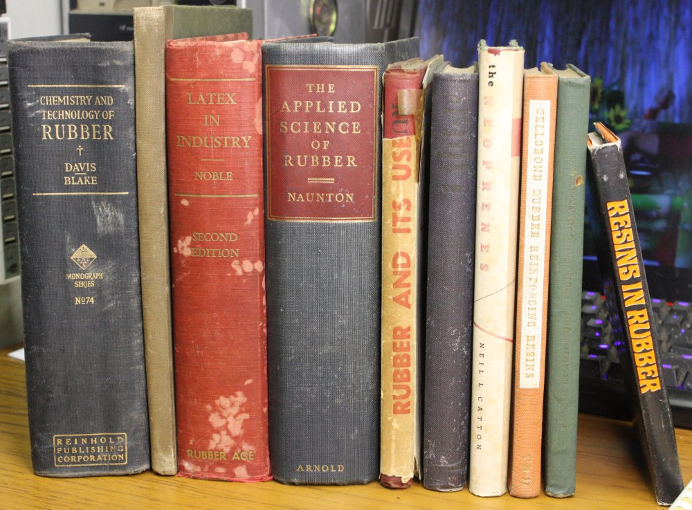
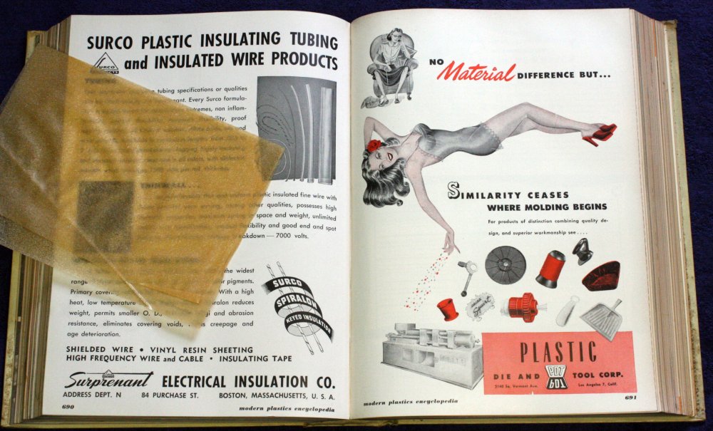
There's a strange anomaly though. Vandals don't seem to bother much with books. It's as if they don't even see them, or there's some kind of repellant effect, like garlic and vampires. An example: Many years ago I found an old chemistry lab in a building that had been involved in manufacture of rubber goods. The entire place had been abandoned years before, apparently as an insurance walk-away after a major hail storm punched thousands of holes in the factory's asbestos sheet roofing, and the interior got well soaked. In subsequent years vandals had smashed every piece of glassware and equipment in the lab. Yet one wall held a bookshelf, and it appeared not a single book had been removed. There was a little water damage, but mostly the books were unharmed.
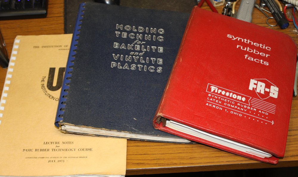
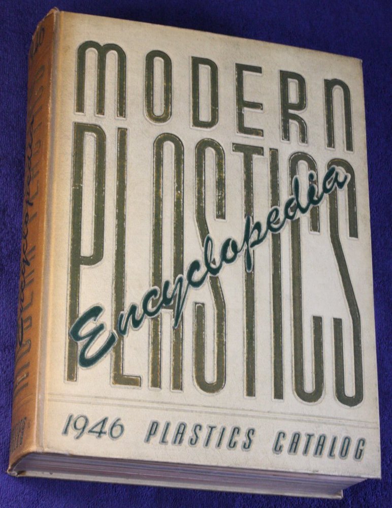
Well, I had no personal need for an archive of books on rubber, but on principle I wasn't going to leave them there to be eventually destroyed. So I rescued about half. The shelves included a series of very large 'Modern Plastics Encylopedia' industry yearbooks, with most years represented since 1946. (Pics 4, 5, 6 below.) I simply couldn't carry them all and was already short of shelf space myself, so took only a few samples of the yearbooks. That's something I've since regretted. I should have made multiple trips to rescue the entire set.
The building didn't last much longer. A series of partial demolitions, a fire, total demolition, and it's now replaced with modern buildings. I don't know what happened to the remaining volumes, but unless someone else saved them (unlikely), they were destroyed.
Pic #2 are some volumes I selected from my set as possibly containing something like a simple description of how to vulcanize rubber in molds, for someone who isn't a professional organics chemist. But I'm not terribly hopeful.
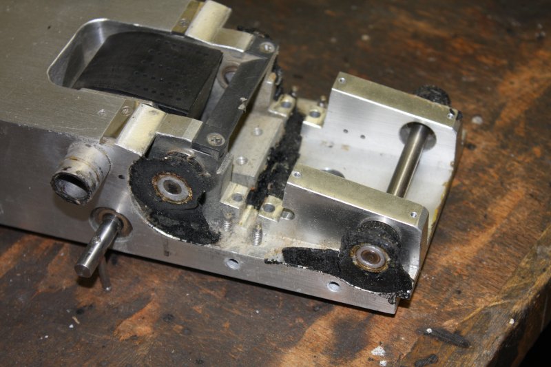
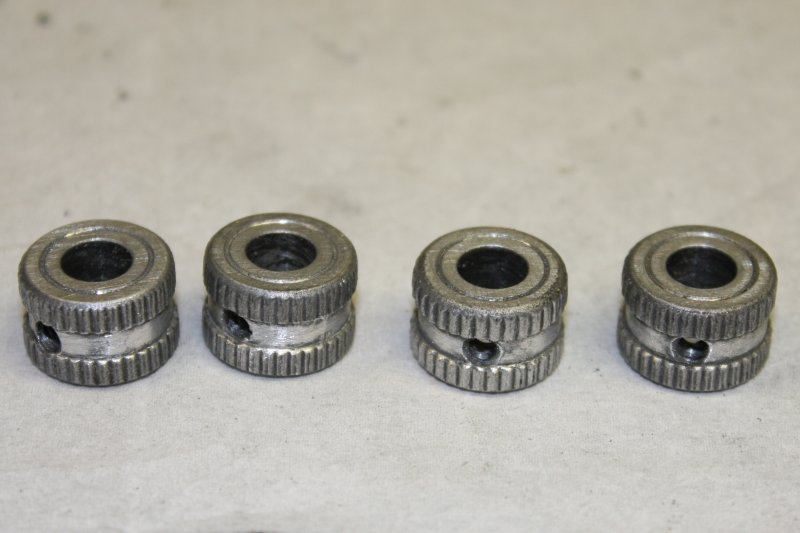
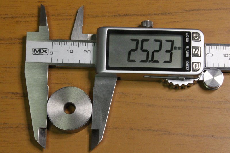
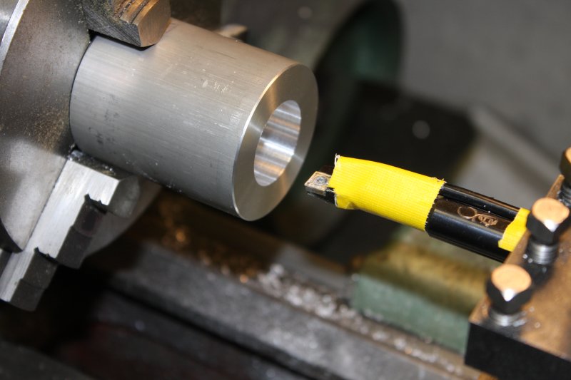
1, 2. Measuring the shaft spacing and steel roller diameter, the rubber rollers would have been 27.1 mm Dia if they were just touching the steel rollers. (Uncertainty about 0.025 mm.) The shafts are 6.35 mm (1/4") Dia.
As for making new rollers, here are the possibles so far:
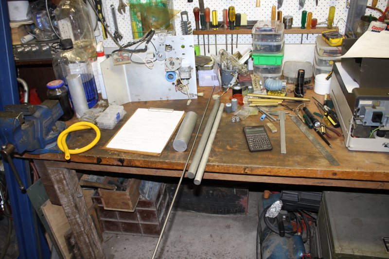
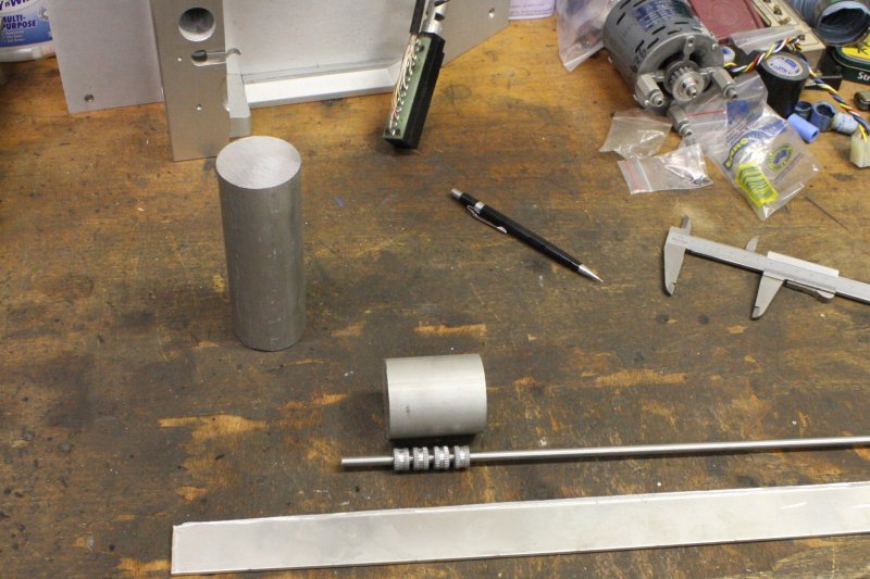
1. Bought materials. Aluminium round bar, 50mm Dia (for making a roller casting mold.) Two round bars 25 and 20 mm Dia, for machining hubs for salvaged silicone rollers. And some 1/4" ground steel rod (actually stainless steel) for a shaft in the casting mold.
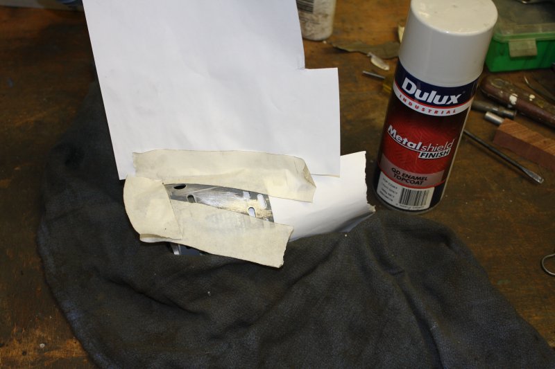
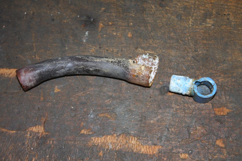
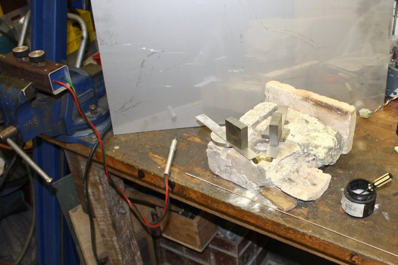
2, 3. To make a replacement of that broken blue plastic hose elbow, I wanted to clearly see the hose path. But when the machine is assembled the path is not very accessible. When disassembled, there's nothing to show the orientation of one end of the path. So, a quick improvisation. Bit of bent aluminum sheet, and some ducktape. Now it's obvious.
1. Oh the struggle! I hadn't yet removed the air blower platform, but it needs to come out for cleaning. It's NOT easy to remove. Nearly impossible without removing the entire card cage structure above it. But I don't want to remove that because it's also a pain to get out, and for fear of breaking something among the tangled wiring loom. On the model M200 the manual shows this platform just sliding out. But in the TM200 they've added a card with lots of trimpots under the cardcage, and it obstructs removal of the motor platform.
So... lots of wiggling and cursing later...
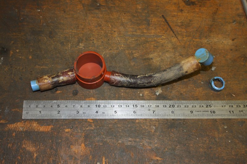
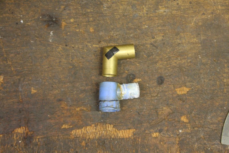
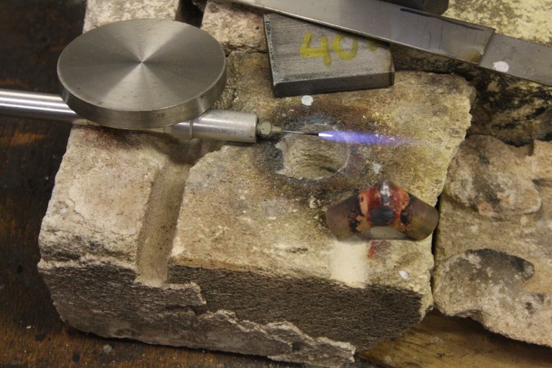
Making that pipe elbow, to replace the fragmented blue plastic thing.
1, 2. Cut the dowel down to a press fit in the tube.
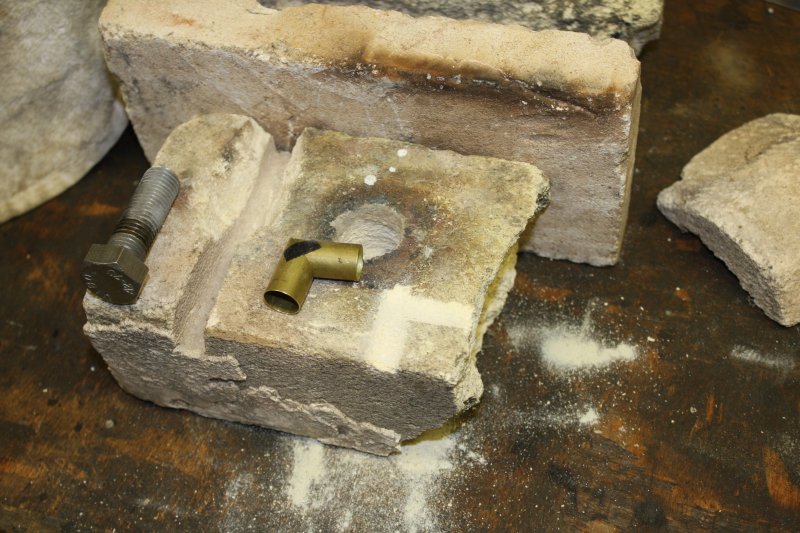
1 - 3. Preparing to silver solder the elbow. A 'jig' made by rubbing troughs in very soft fire brick.
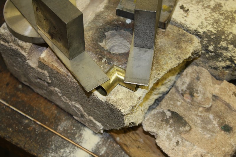
1. The elbow in place. Sadly, the tubing ordered from Aliexpress will take nearly a month to arrive.
The obvious method was to make a simple mold and do one roller at a time. Sounds good, doesn't work.
Really, all four rollers should be cast in one go, from the same mix batch. Which should all be vacuum de-gassed, and the mold should be vacuum poured.
And then in addition, I want a system that allows iterations with increasing roller diameter (without too much waste and rework), if my first guess at a workable size turns out to be bad.
Anyway, the plan is to bore a cylindrical hole through a bit of this 50 mm Dia bar, with a hole diameter equal to the roller OD. Then the original hubs will be alternated on a shaft with spacer disks, machined to be close fits to the inside of the cylindrical mold. The disks will have a couple of holes to allow the silicone compound to flow between the roller spaces. End clamps to hold everything in place, and pins from the side to form holes for the hub grub screw allen key access.
Well, let's begin.
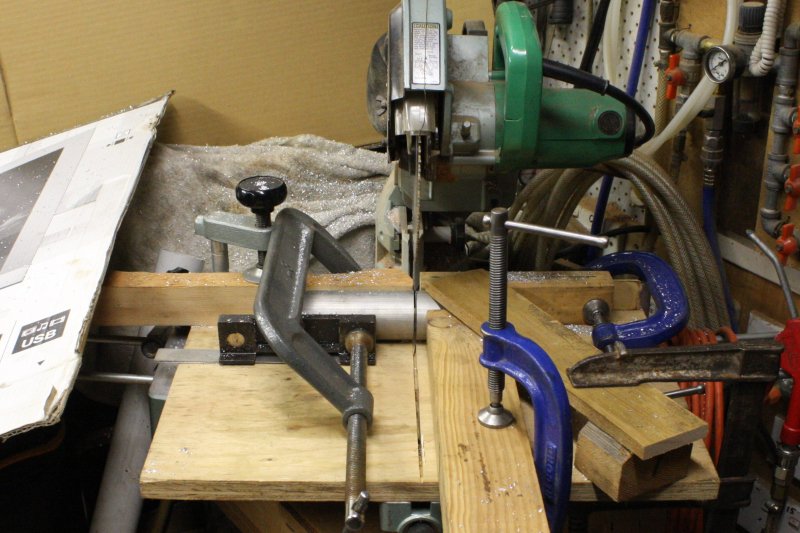
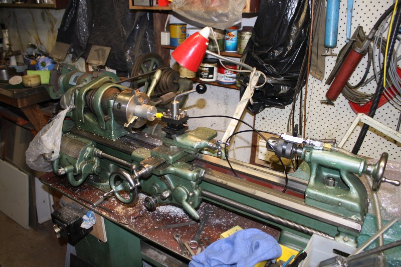
1. The only means I have to cut the 50 mm bar, is a drop saw. Meant for cutting wood it works on aluminium, but lacks suitable clamping arrangements. Hence this circus of G-clamps. The small section being cut off must be clamped too, lest it rotate into the blade once free.
One of the best things (for me) to come out of the Australian computer museum society move, was being prompted to join a couple of mailing lists focussed on vintage computing. This has been very helpful.
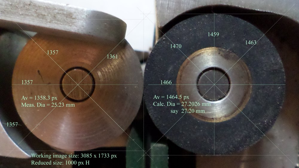
Here's the cropped section of the image I used to derive the rubber roller dimensions. (Also reduced in size to post.)
From the shaft spacing I'd determined the rubber rollers would be 27.10 mm Dia if they were just touching the steel rollers. From the photo they are 27.20 mm Dia.
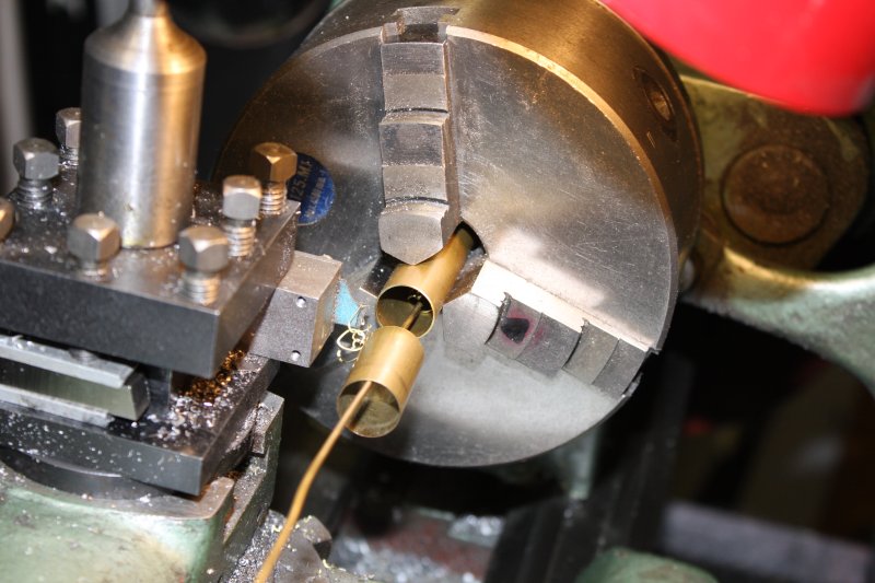
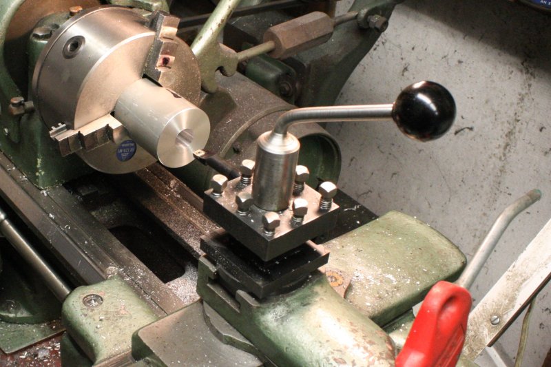
1 - 3. The inner surface of the mold should be nice and shiny. Swarf left loose inside while machining can score the surface, and I wanted a reliable way of clearing it out as machining progressed. So rigged up this fixed air blower right at the boring bar cutting tip. A small nylon tube, feeding compressed air via a ball valve for adjustment. The first try used a nylon wiretie to secure the tube end, but that rubbed on the inside of the bored hole and got rotated around, so I replaced it with gaffer tape.
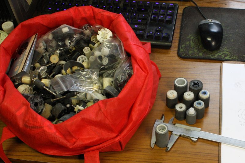
4. The air was blowing chips out via the lathe spindle bore, and I was removing quite a bit of metal. So to save work later vacuuming the chips off the floor and piles of stuff beyond the lathe, I rigged a shopping bag to catch them.
5. Done. I don't often go to the trouble of doing running calculations of 'how much more to remove', considering the nuisance of converting every measurement back and forth between thou (lathe dials are Imperial) and metric (my vernier calipers.) This time I did.
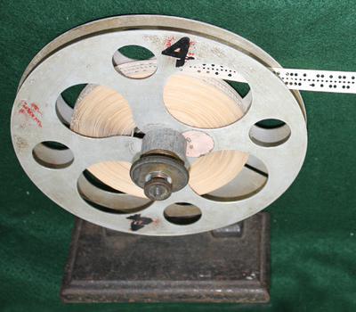
1 - 4. As found at the ACMS warehouse, except that the tape end was loose on the roll. The correct threading was obvious.
Helpfully it has a nice picture.
Hopefully, somewhere in the huge warehouse piled to the ceiling with highly churned old computing gear. With people picking over it all every day, and carting off as much as they can fit in their cars. (I was one of them.)
Would I find it?
Only if I'm really, really lucky.
Every time I went there I kept my eyes open for this. After each trip there I'd be a bit more pessimistic about finding it.
By the last day I went there the main storage area was almost completely cleared. All the shelving gone, with only a few random items left scattered about on the floor. I'd given up on finding this tape reader.
There was a side room, still with a lot of stuff. Most of this was uninteresting. Things like boxes of raid-array hard disks; old ones, just a few gigs, and drives formatted as raid arrays are generally not readable as stand-alone drives, so not even interesting for data archaeology. Plus lots of random junk. I happened to be searching through this looking for a box of plotter pens I thought I recalled seeing, that might suit the big chart plotter I'd rescued.
And there, sitting in a box of utter rubbish, was the missing part.
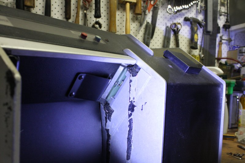
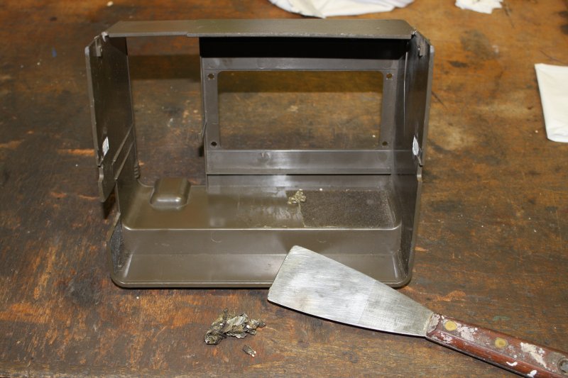
1, 2. Here it is. The plastic case is badly cracked on both sides and here I've already separated the mechanism from the case. Unfortunately the chad bin is gone. But that I can improvise.
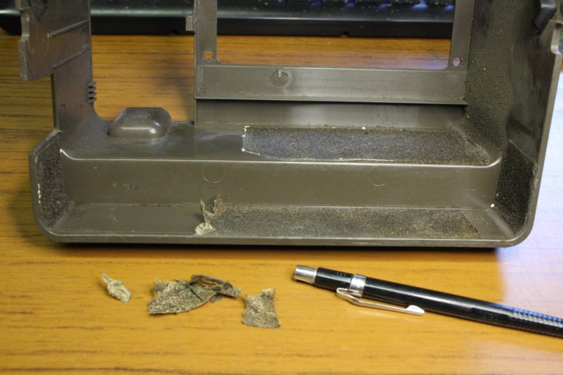
3. Most of the internal faces once had slabs of sound-absorbing urethane foam attached via double sided sticky tape. The foam is inevitably decayed to nightmare, but scrapes off easily. Leaving the tape. I hate this stuff. The adhesive is stronger than the tape film, making removal an extreme pain. On metal surfaces it can be removed by heating the surface with hot air, to soften the tape glue enough to allow peeling it off. Still usually in little pieces since the film tears very easily.
That won't work on ABS plastic, as the case will melt before the glue goes soft enough. But the sticky tape has to come off before I can attempt to repair the case cracks. I was a bit stuck.
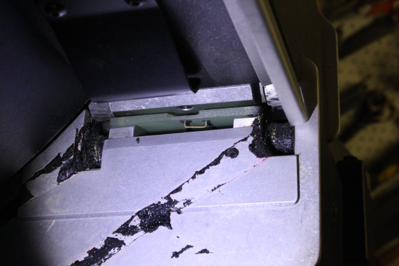
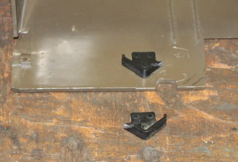
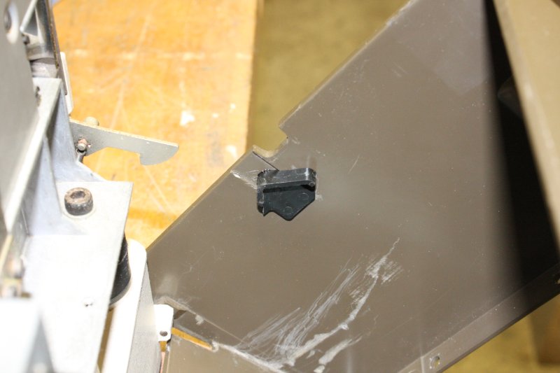
4. Meanwhile, what to do about the broken mounting clips? It was obvious what had happened. At some time in the past someone put the unit down far too hard (or totally dropped it) and the front part had broken loose. It's held on by a couple of side clips (metal clips catching on these black plastic stops) and two pivot pins at the bottom. The black plastic bits are snapped off, and the case fractured around the pivot pins.
I found these black plastic stops are glued on... and the glued face could be cleaved off with a knife slipped into the join. That meant these parts could be swapped, which inverts them, putting their intact sides in position for the metal clips. There's a slight molded recess in the case sides that provides accurate alignment. I reglued them with drops of MEK. Solved!
5. I found I could scrape the double sided tape off with a sharp metal edge, so long as I only did narrow strips. That adhesive is tough! After that the remaining adhesive was susceptible to mineral turps.
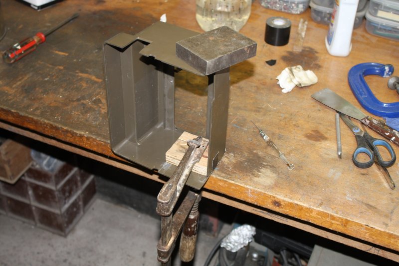
1. Gluing the case cracks. ABS melts very well with MEK, almost too well. The problem is how to avoid getting any MEK on outer case surfaces, since it ruins the surface texture. Makes it look 'melted' — because it is.
The best solution I know is to use ducktape on the surface to protect, and make sure it's very well adhered. The tape stops the MEK from surface-creeping.
Then leave it alone for a couple of days. The MEK takes a while to diffuse out, and until it's all gone the ABS remains soft.
2. Gluing on those retaining clips. I'd scraped back the previously glued surfaces to clean plastic first.
1, 2. Just starting on the many bits of sound absorbing urethane foam in the punch unit.
I still have not taken the main punch unit case apart, because... ha ha, I'm not really sure how to open it. It's not obvious and I don't want to just start undoing random screws since there are things like a tensioned cable from the rear reel mechanism to the front punch tape-load lever. I might have to (gasp) RTFM.
Integrating the work of Oersted, Ampere, Faraday, and others, James Clerk Maxwell developed a set of equations, formally unifying electricity and magnetism.
Baudot's coding was devised as an alternative to Morse code, allowing a fixed-length (5 bits) transmission per character. But these were all for human convenience and improved efficiency of line operation. They did not enable passing recorded information into the telegraph system.
goog: heaviside transmission line
New Zealander Donald Murray optimised the Baudot multiplex and his own automatic system. Murray code was also five bits, but chosen so the most-used characters produced the minimum movements of the mechanism. The Baudot coding was devised solely to be easy for humans to remember.
Piano roll, 1918.


Saurer & Plauen embroidery machine tape
  history of saurer machine embroidery

Computer punched cards

8-bit punched tape
My own encounters with paper used for data recording were:
This story is about the process of refurbishing and interfacing these old machines, and archiving the data recovered from those paper tapes. I did the restorations in parallel, but will relate them separately.
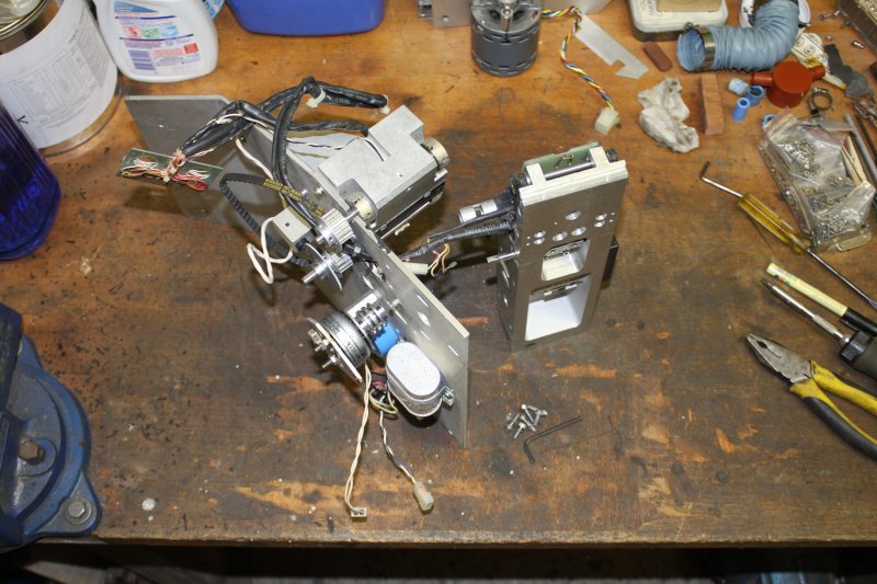
The Documation TM200 punch card reader
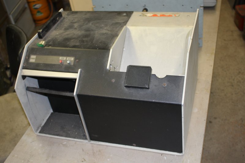
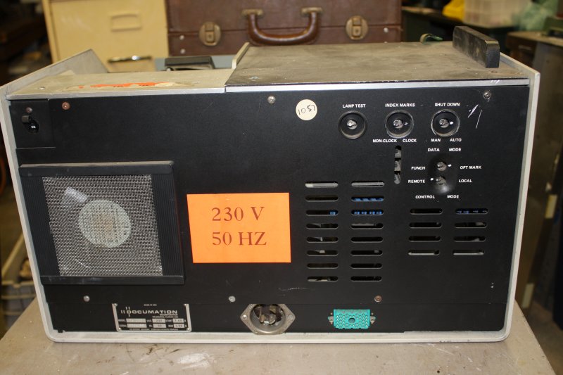
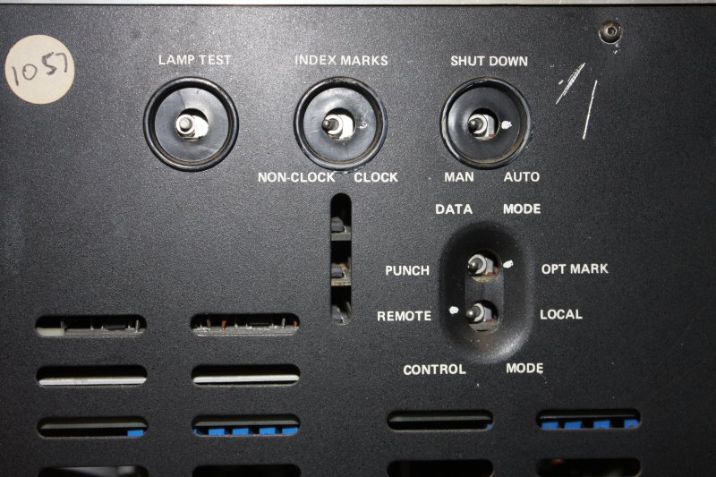
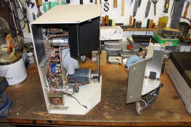
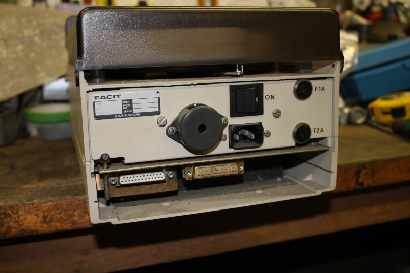
2 - 4. Back panel. The TM200 is quite a late model, and can handle both punched and mark-sense cards. Good, but on the other hand it means a manual is hard to find.
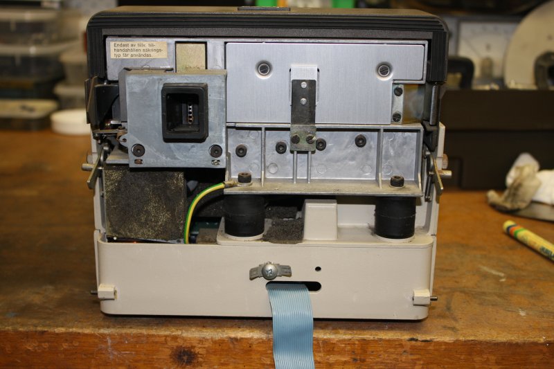
5. Cleaned up a little.
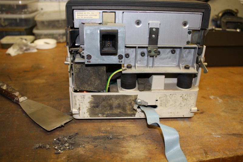
Immediately the problems start appearing. That blue hose end is an air intake, and should have a dust filter. That was a block of open-cell urethane foam glued to the back panel, and has long ago disintegrated.
2. Both air hoses seen here are decayed and hardened with age. The hose junction at far rear (blue plastic) is fragmented.
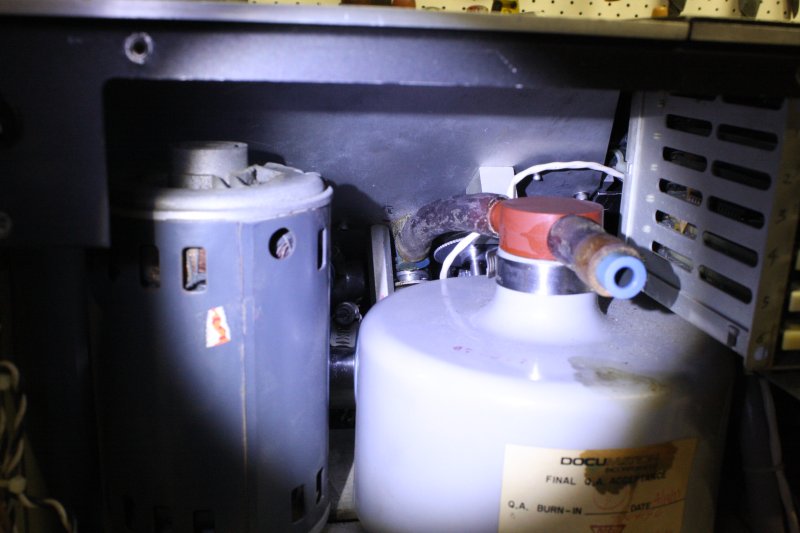
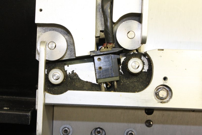
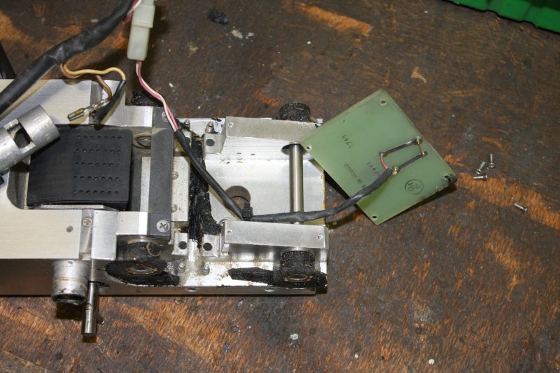
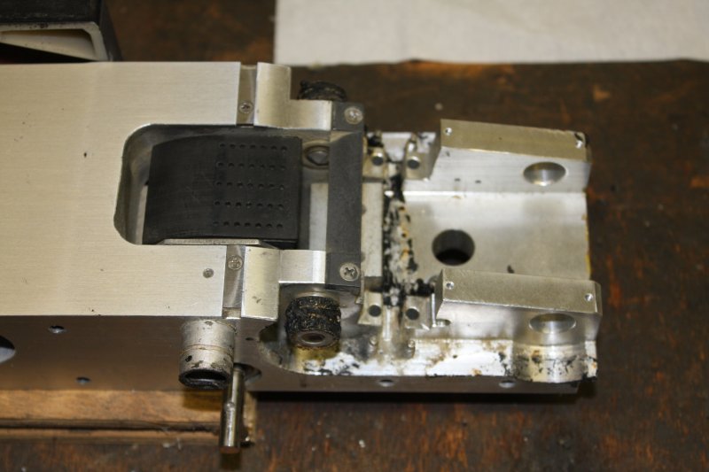
3 - 5. Urk. In which we learn that rubber rollers in the card transport path, are now dribbles of congealed black goo. Old soft rubber is known to do this. The chemical crosslinks unlink, turning it into a tacky liquid with the consistency of treacle. It may later set fairly hard again as oxidation continues. Both have happened here. The goo has also flowed into bearings. Great.
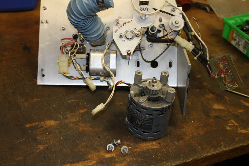
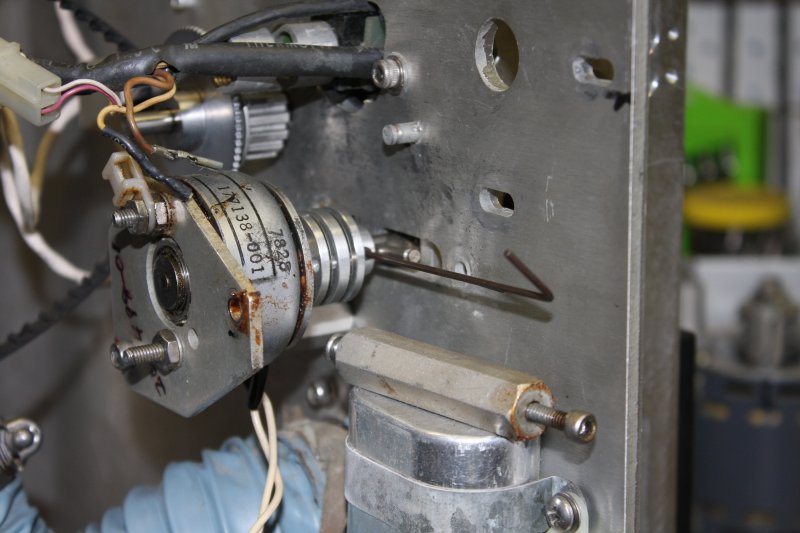
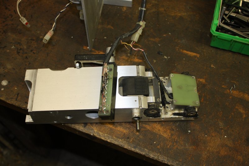
4. Turns out the gunk has also dribbled inside the transport motor, which is seized by the set-hard crap.
5. Slight mystification. This blank panel with the gunk dribbles is attached by 'secret screws.' Where are they? I put it aside for now.
4 - 5. The gunk was impossible to remove from the painted exterior without also removing the paint. I didn't have a correct shade of gray paint, but it's inside the cabinet, so used a light gray. Who cares?
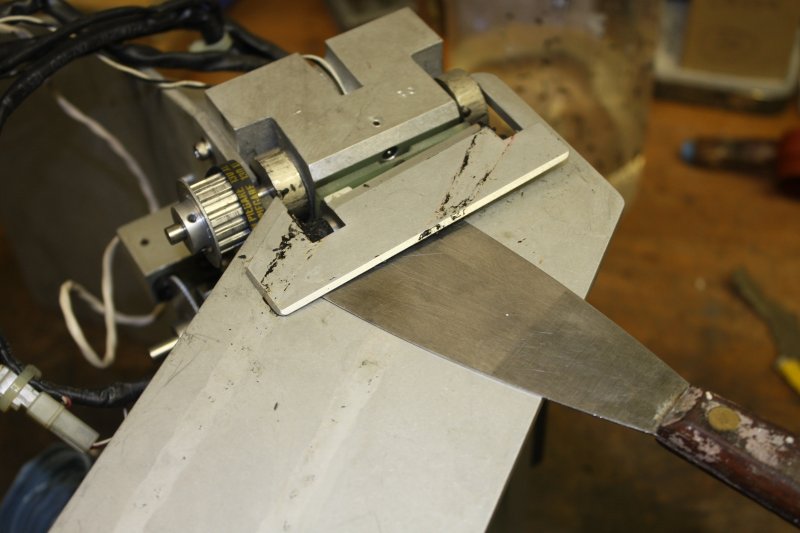
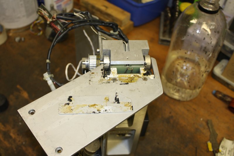
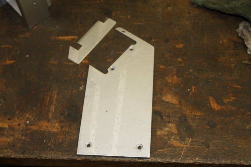
2 - 3. Finally figured those 'secret screws' had to be under this cover, which had to be glued on. It was.
4. Cleaned, but unfortunately the gunk has changed the colour of the anodizing. So the marks are not reversible.
5. Another sad problem. The status display block is molded of clear plastic, with brass threaded inserts. Typically, the plastic around these is fracturing badly. Still holding together, but not for much longer I suspect. Need to determine what plastic it is, and whether a solvent can re-bond the cracks. (Without risk of misting the front face.)
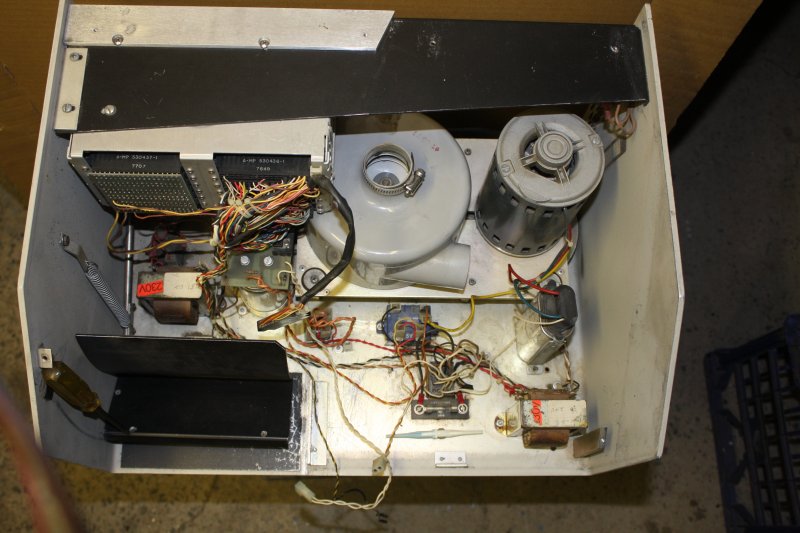
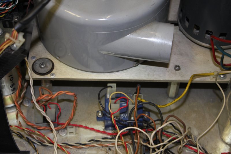
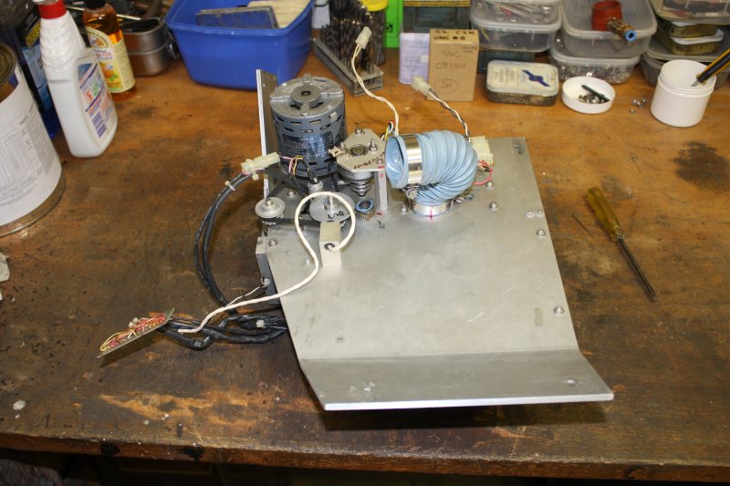
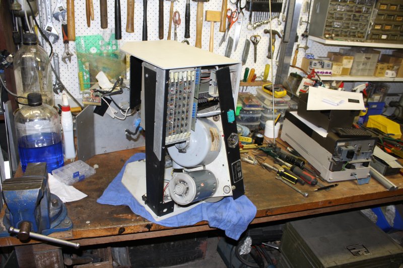
2 - 3. The suction/blower fan and its motor are on a vibration-isolated base, which has rubber mounts. These are sagged, so a couple of transport securing posts are touching the cabinet base. Perhaps I'll add springs around these posts to take most of the motor weight and lift the assembly slightly. As it is now, it would noisily vibrate against the case when the motor-blower unit is running.
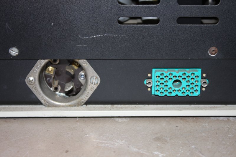
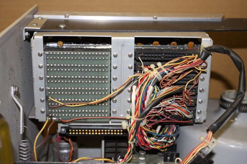
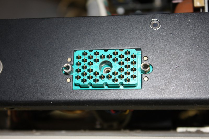
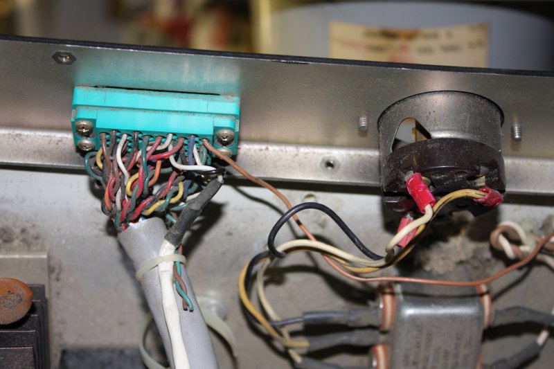
4. Card cage rear wiring. So very 1970s. The empty socket connects most of the wiring to the card transport block.
5. A tool thoughtfully included, and not lost by Mr Ape. (He probably never used it.) I think it's a connector pin extractor. Also some more signs of water ingress.
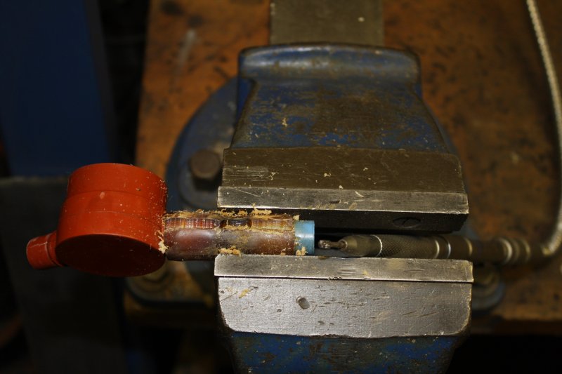
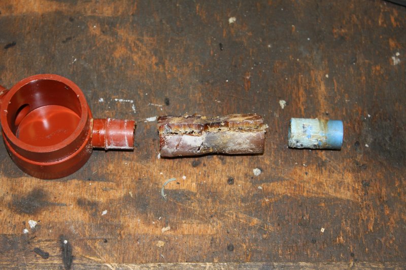
2. It's very rigid now. To get it off the plastic pieces without risking breaking them, I cut grooves in the ex-Tygon with an engraver till almost all the way through. Then 'bit' the groove sides apart with large sidecuters, avoiding applying force to the inner plastic parts.
3, 4. The decayed Tygon has chemically damaged a surface layer of the blue plastic parts. Fortunately only the plain tube bit matters, and that is thick so the decayed surface could be simply scraped off. That tube is an airflow limiter, and its inner diameter is important to operation of the card input stack picking mechanics.
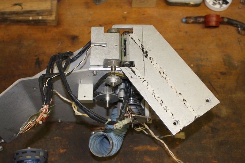
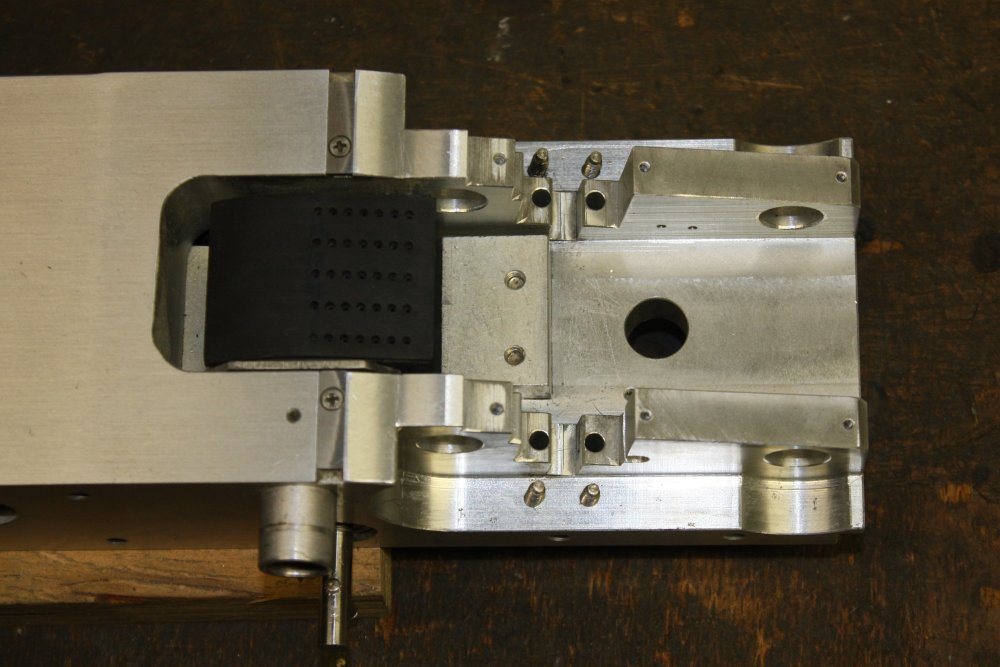
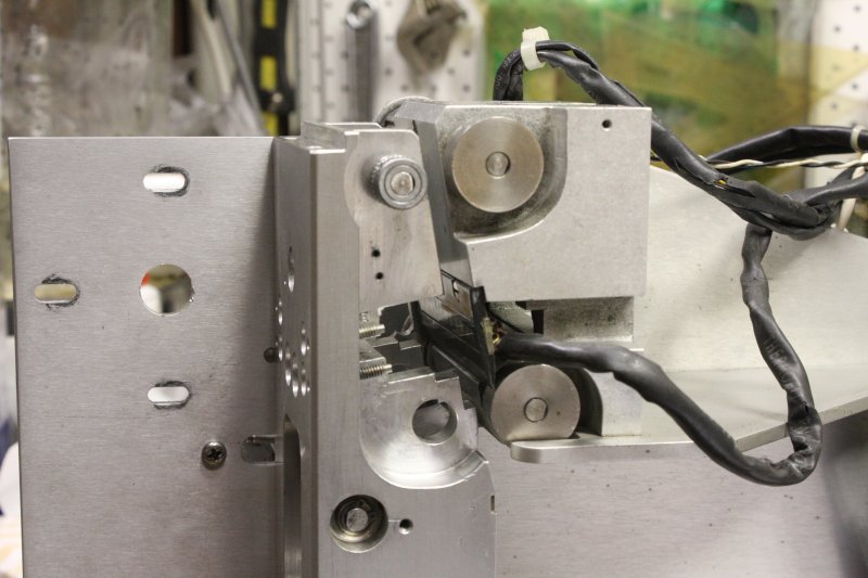
5. Preparing to remove the card transport mechanics block. Plenty of potential to upset adjustments here.
2. The air blower hose has seen better days. It had a small piece of plain electrical tape semi-attached at the tear. Seriously Mr Ape?
3. We have separation.
4, 5. Wired parts removal.
2. Progressing. It's turning out to not be too bad. The bearings are OK.
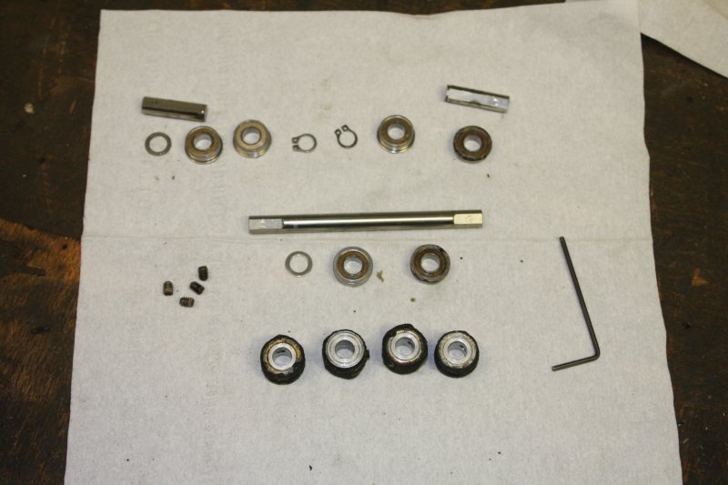
3. All the roller shaft parts. Amazingly, either Mr Ape has been here too, or when this was first assembled they left out a few spacer washers. There are two here, and I'm pretty sure there should have been four.
At the bottom of this pic are the four degraded rubber rollers. Finding or making replacements for these will be the biggest challenge with this machine.
Fortunately the rubber rollers are not driven, they just press the card against metal drive rollers. So their diameter won't be super critical. Just fairly critical. And I'll probably have to guess.
4. The transport block cleaned.
5. The cleaned hubs from the old rubber rollers. Now, how to replace the missing rubber?
Here's a discussion thread on eevblog forum.
Anyway, some questions:
The Rubber Library
It's a rather amusing coincidence that I happen to posess a small library of text books related to rubber and its industrial manufacture. This is a short tale in itself.

A sample punch card I measured is 0.15 mm thick.
It was amusingly serendipitous. On a suggestion from that eevblog thread I googled for two-part molding silicone suppliers in Sydney. Three came up. Two of them long drives away, and one (Aldax Molds) right by a road I drive at least twice a week (on the way to do my old mum's weekly shopping), and would be driving tomorrow!

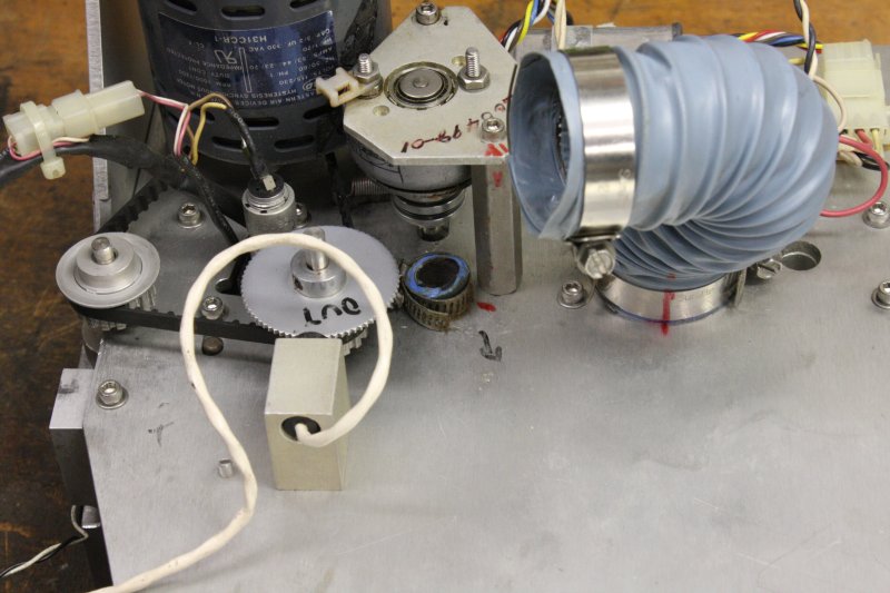
The yellow tube is a sample of thick walled silicone tube, salvaged from a dishwasher. I've been trying to find something from local suppliers like this, but larger (14mm ID), as required for the card feed suction hoses. It needs to be highly flexible. No luck so far.
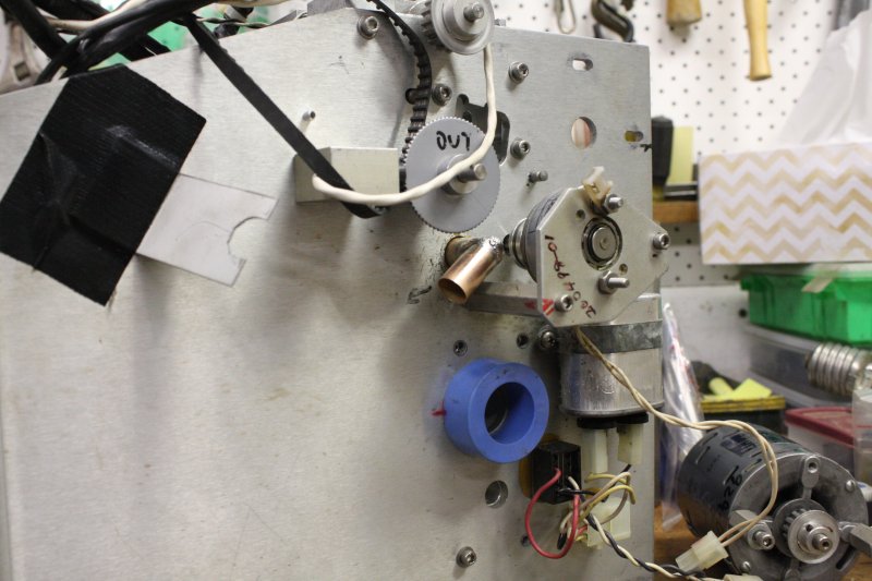
2. Finally it's out. Very dusty, and some corrosion on the belt pulley. Had to be done.
3, 4. Then there's this bundle of joy. A plug type I've never seen before, and had no idea even where to begin looking for a mating connector. But thanks to a correspondent here's a source, from Mouser.
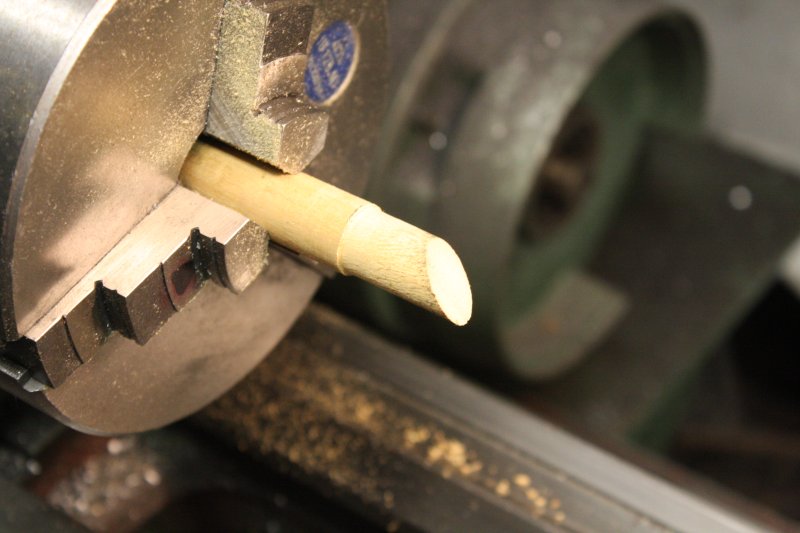
1. Cutting bits of thin walled brass tubing. I happened to have some suitable sizes. And a miniature parting tool made with an old hacksaw blade.
2. Rough arrangement. But what's the join angle?
3. Cat. Can't get up. All work stops...
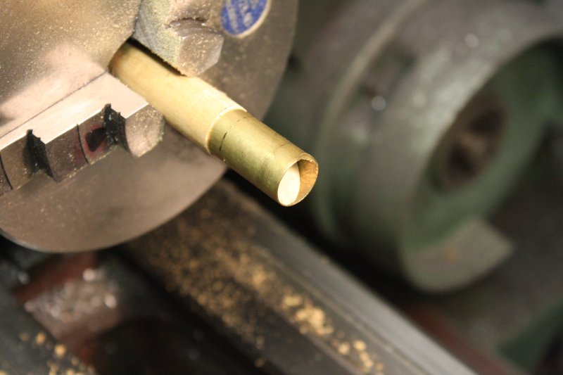
4. The blue elbow is 10° off a right angle. Which seems about right for the pipe path. So, the brass tubes have to have 40° cuts for the join. How to get that right? It's not easy to hand cut this fine brass tubing, and impossible to cut it in the drop saw.
5. Ah ha. Cut a bit of scrap wooden dowel to 40° and slip that inside the tube as a hand cutting guide.
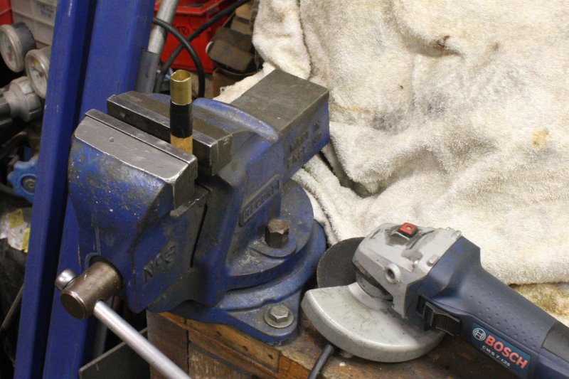
3, 4. Angle grind the tube down to match the wood angle. Carefully! The angle grinder can hardly even feel the presence of the tiny brass tube. Basically like grinding on air.
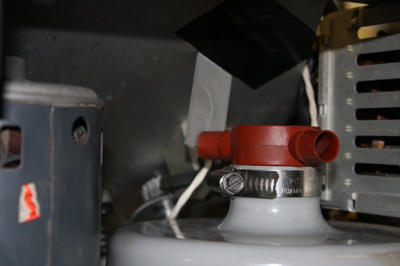
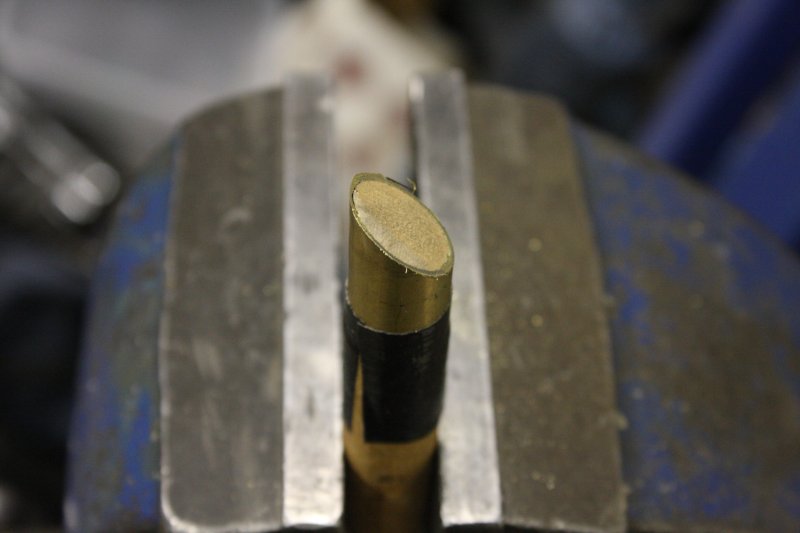
5. Well the angle worked out. Yes, the two bits of tube are slightly different diameter. One is a press fit on the metal tube projecting from the reader chassis, the other is 14mm OD to fit the silicone tube I've ordered.That has to match the red plastic tube fitting on the air blower.
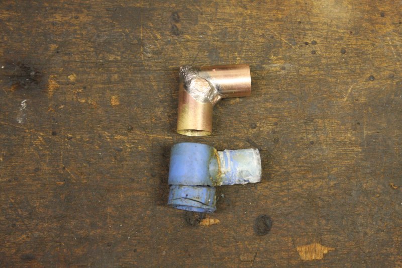
4, 5. Done. My silver soldering is like my welding; pretty poor but does the job. Not helped here by using fat plumbing solder rods with the lowest available silver content (ie cheap.) Thus high melting point, that makes it hard (for me) to avoid burning some of the silver off. Result: bumpy solder surface. The mini-torch burns oxy-propane, and uses replaceable syringe tips.
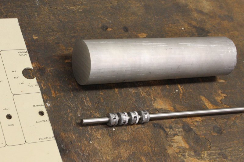
2. Bits for the roller casting mold.
This was an interesting design problem.
For one thing the curing time of the compound before demold, is 24 hours. Another problem is that it won't be easy to mix up very small quantities of the two part compound. Or to get the ratio exactly the same each time. So if I do the four rollers separately, they may have slightly different properties. That's probably not good, since it might make the cards feed badly.
Plus for reliable bubble-free casting, the liquid should be vacuum de-gassed before pouring into the mold. Not to mention how to ensure there are no voids formed in the mold.
The outer surface of the roller has to be smooth, with no casting blemishes.
The machining and casting settup has to guarantee as close to zero eccentricity of the roller as I can get.
Also I guess, a construction that might be workable with a future attempt to do vulcanized rubber versions, if everything else fails. So, a mold that could withstand pressure injection and the vulcanizing heat stage.
Oh, and it has to be possible to get the rollers out of the mold too.
Mold release on surfaces of the mold and spacer disks, but not on the hubs.
The whole thing in a vacuum chamber together with the container of mixed compound. Everything pumped down to de-gas the mix, then that poured into the top of the mold. Air let into the chamber, compound gets sucked into the mold (that is airtight everywhere except the inlet port.)
Nice plan, but I know how those go.
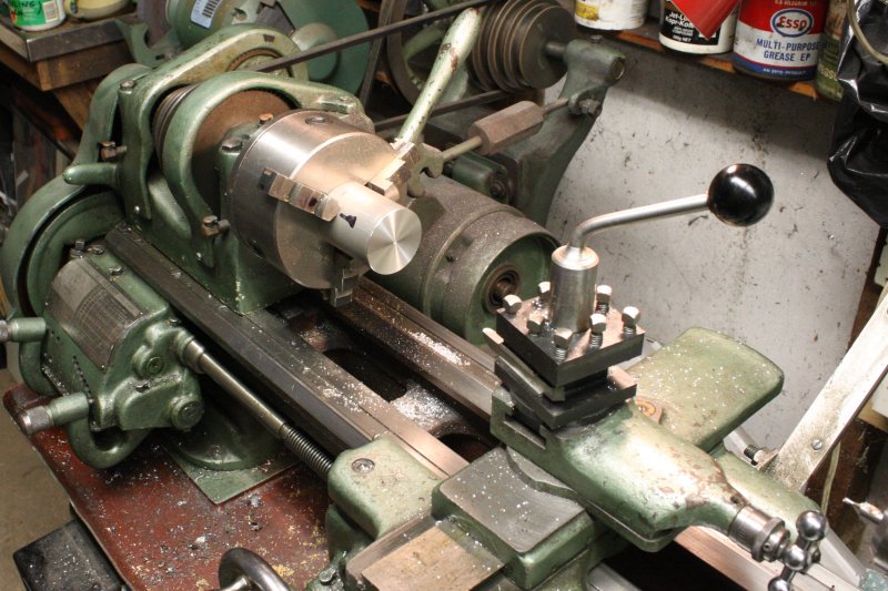
2. The short bit will be the rollers mold.
3. Facing an end.
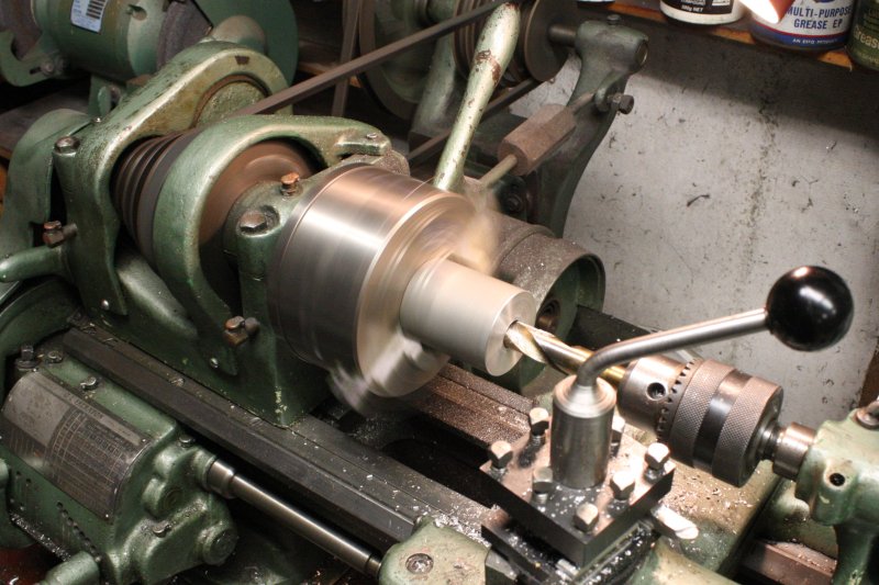
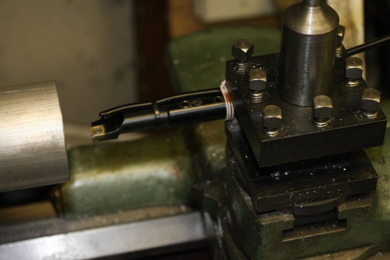
4. Started with a center drill, then a 1/4" drill all the way through, then this 16mm drill right through. Just to make a hole big enough for...
5. A boring bar. With this I can bore the hole out to the final diameter for casting the rollers. The surface has to be clean, since the silicone will take on that surface finish. Hence the air blower, to keep the cutting free of chips that could mark it.
The Rub (here it is)
Well, now I need to decide finally on what dimension I'm going to try for the first attempt at the rollers.
Hmmm...
For instance someone sent me this very clean hi-res photo of an intact roller on a Documentation M200 card reader. This has the same transport mechanics as my TM200. (Reduced from the original 4608 x 3456 pixels to post here.)
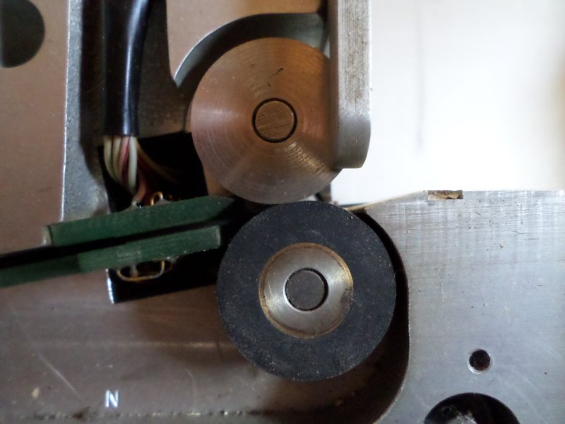
That was surprising. I'd assumed the pinch roller would be more squished against the steel roller. But actually there is only 0.05 mm of resting squish, which is barely visible even zoomed into the full size photo. The cards are about 0.15 mm thick, making 0.2 mm of roller squish total. Apparently that gives enough friction to drive the card. Depending on the flexibility of the roller of course.
20181115 After a pause
The usual story — bunch or other things came up. The big laser power supply, and some more computing antiques. Almost a month passed before I got a chance to machine the outer cylinder for the rollers mold.

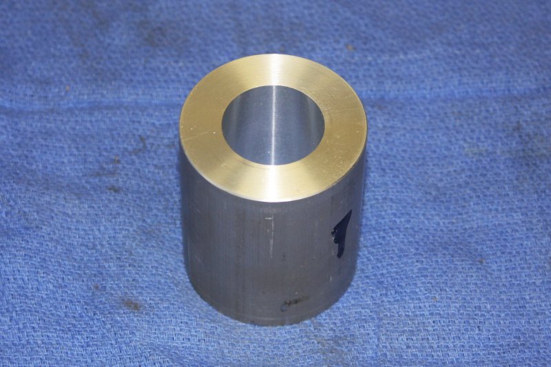
The target ID is 27.20mm. Starting with a hole measured at 24.2mm, I did three passes with the boring bar. The last pass taking off just 0.025mm (1 thousandth of an inch.)
Final measured ID: 27.20mm. Yay. (Ha ha, to a real machinist this is ho hum, but I'm quite happy with it.)
More to come...
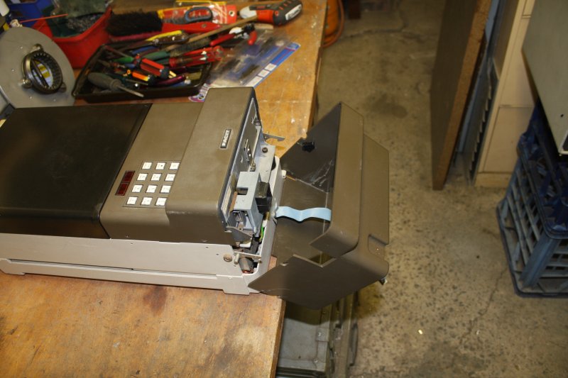
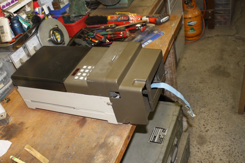
The Facit 4047 paper tape punch/reader
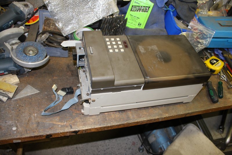
What wasn't obvious was what sort of thing was supposed to be attached to the front end of the machine. It was just missing, with only the bare ribbon cable and some dangling clips as clues. The connector pins at the cable end were bent hard-over, suggesting the parting had been forceful. Not a good sign.
 Hunting for 'Facit 4047' online, I found a user manual at Bitsavers. (6.6MB)
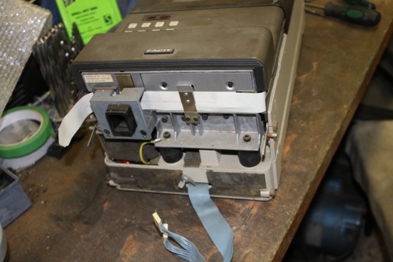
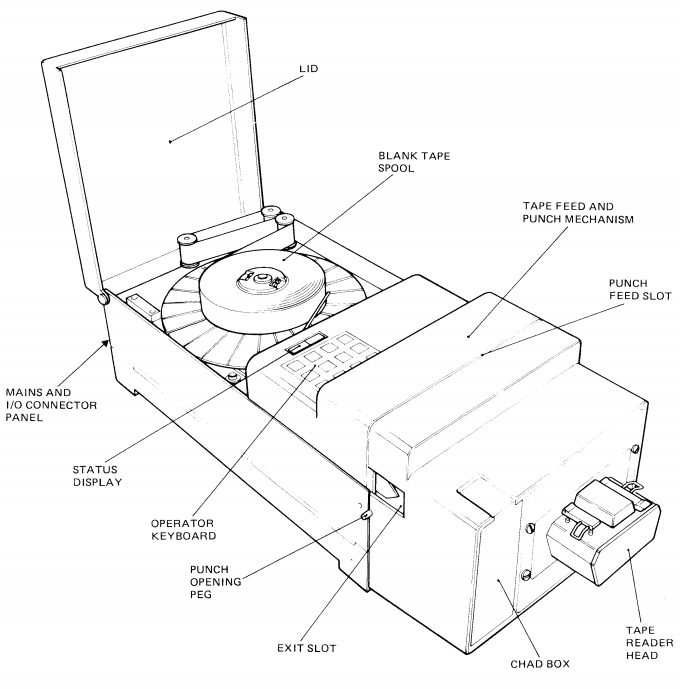
The missing front part is a tape reader.
This is what it looks like.
But where is it?
Not sure what I'm going to use as replacement sound absorber. It probably will need something; punches are always very noisy.
Also ducktape is slightly stretchy, so if you strongly stretch it while applying across a crack, it pulls the crack closed. Here I was using it to do both services. So, tape the cracks, apply a small amount of MEK to the cracks inside with a glass syringe, flex the cracks slightly to make sure it penetrates, then clamp between flats to ensure the cracked surfaces are aligned.
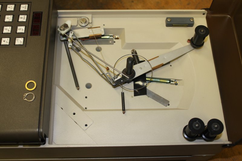
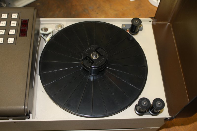
3. Under the tape supply reel. The mechanical complexity here was surprising at first.
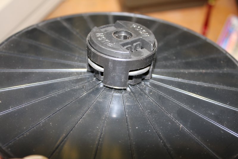
4. The reel hub. There's a rubber O-ring that locks the tape roll in place firmly — if you operate the hub center mechanism correctly. Someone hadn't, and had just pushed the tape reel down onto the hub while still in 'locked' position. That had displaced the O-ring so the lock couldn't work. I've put it back in the right position for this photo.
5. Cleaned, and the slack take-up roller held back by the magnetic stop.
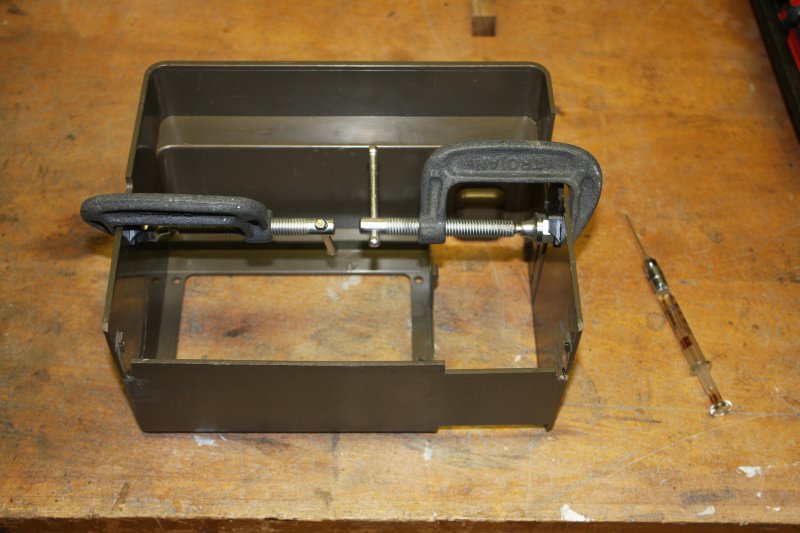
3 - 5. Trial fitting of the repaired case. It works, but I'm still going to reinforce the glued cracks with glued-on laminations of ABS sheet on the inside of the case.
More to come...