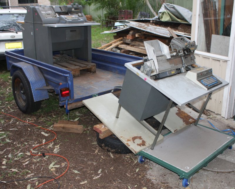
 An email "help, please pick up some stuff", a car and trailer trip to a factory storage space, and this is the result.
20181104 TerraHertz http://everist.org NobLog home Updated: 20190517
It seems like a pattern is setting in, where every time I get well into a project, there's some kind of priority interrupt that can't be ignored and which involves absolutely having to do something else for a while. As if the long list of sidetracks in Searchlight, Deluge, HP_9830A, Data in Holes and the huge laser power supply (not yet written up) weren't bad enough, it just happened again.
An email "help, please pick up some stuff", a car and trailer trip to a factory storage space, and this is the result.
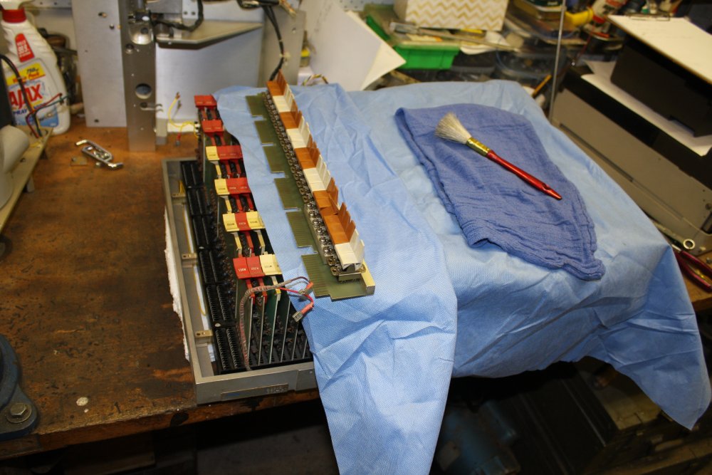
← Unloading the trailer.
The car was full too, and now my storage capacity is completely stuffed. But what can you do?
Urrgh, I haven't even had time to write up work on the 9830A.
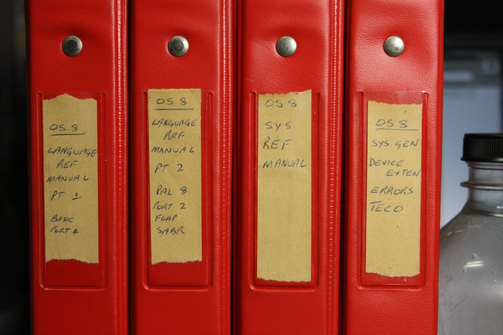
Despite the bulky stuff, this brown cardboard box was the real treasure:

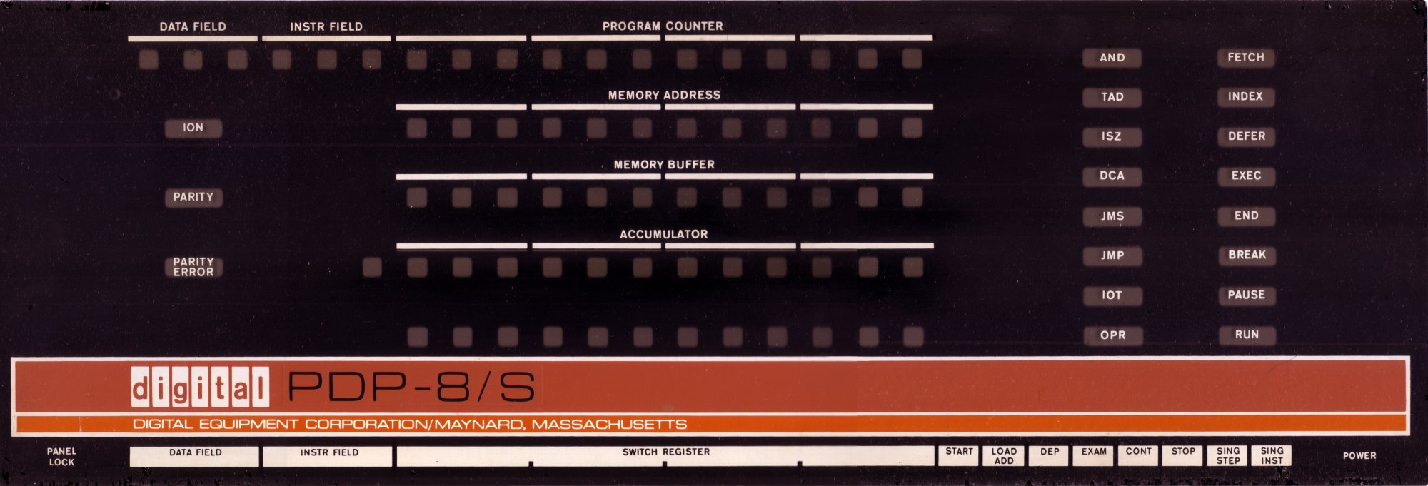
Written on the box is "PDP-8/S & books". And that's what it contains.
It took me a day to unload the trailer by myself (no forklift) and store the other stuff away as compactly as possible. I'd planned to simply stack the PDP-8 box for the time being too. But couldn't resist the temptation to have a quick look.
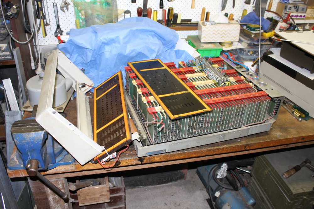
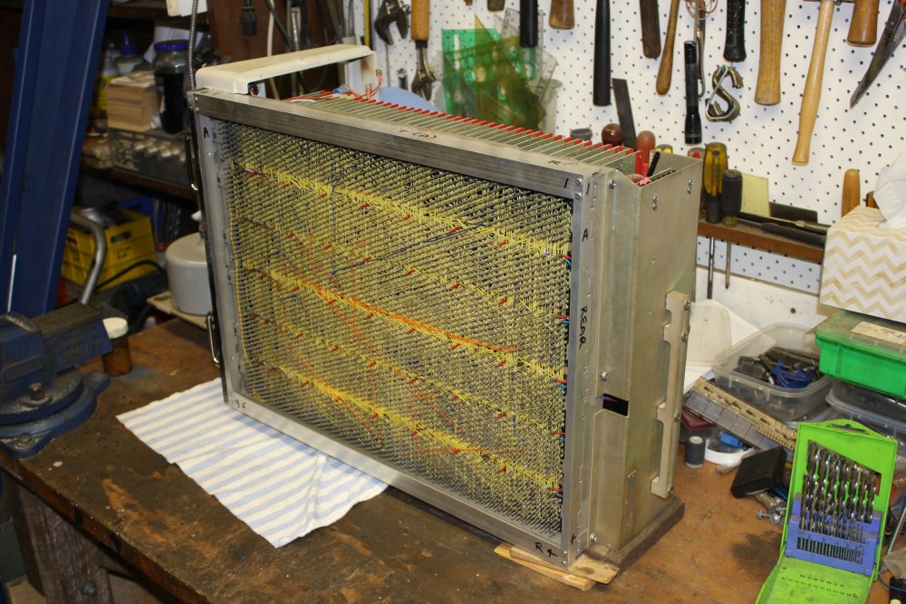
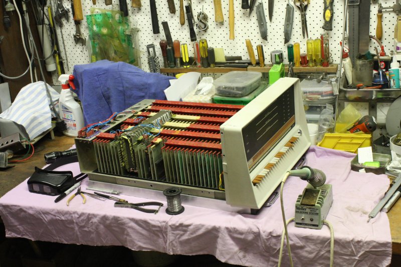
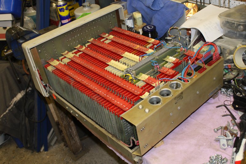
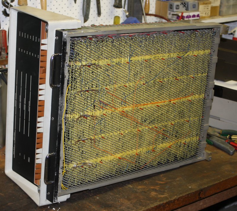 Well, it's beautiful. But there are some obvious problems. It's missing the front panel lights PCB, case top and bottom, and power supply. There's zero I/O, it's dusty and dirty, and some of the cards have popped out of their slots.
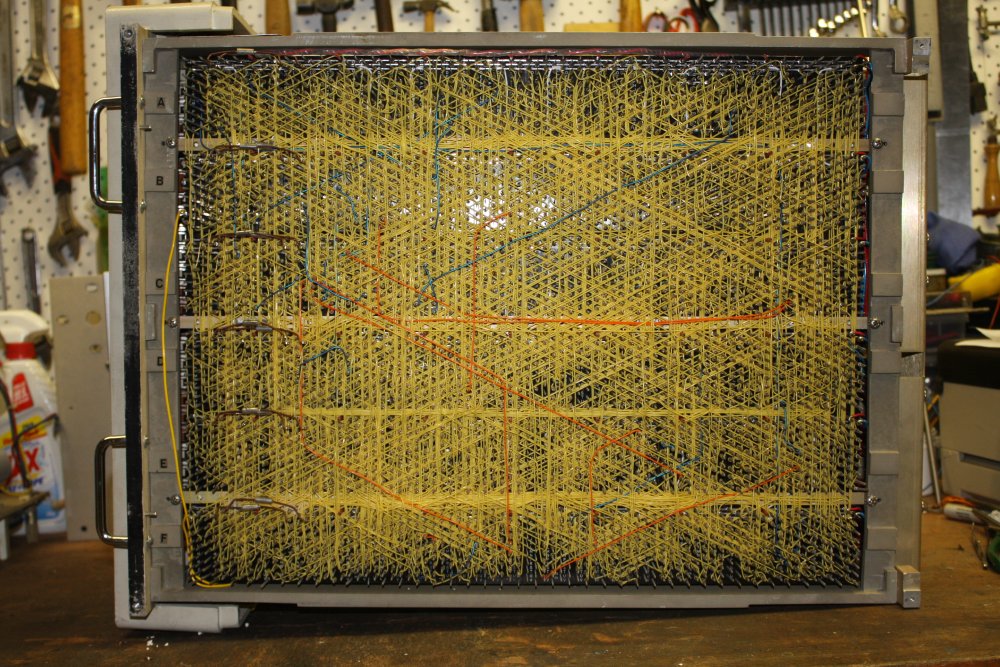
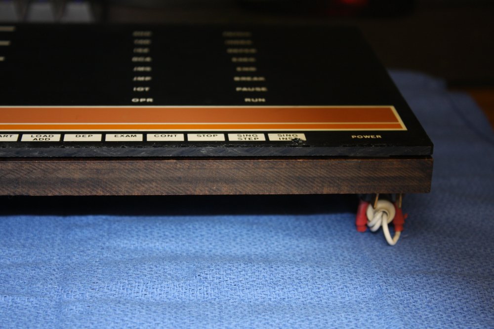
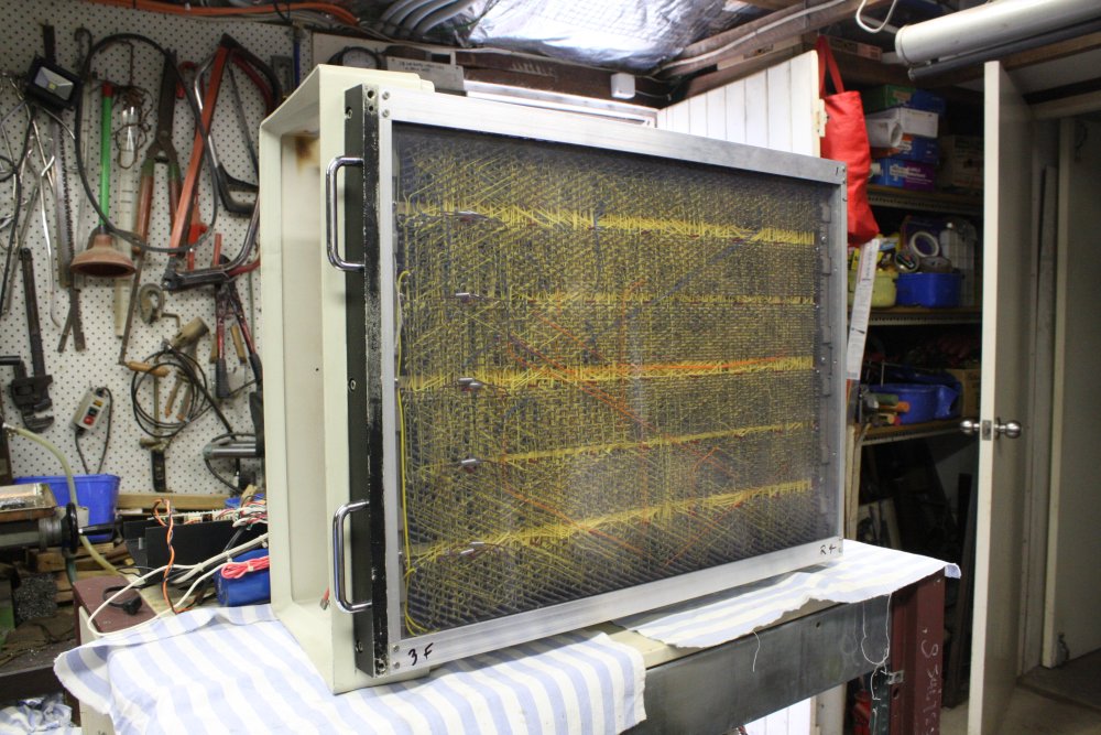
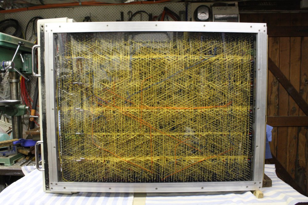
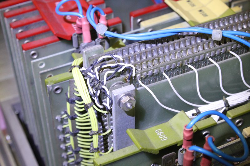
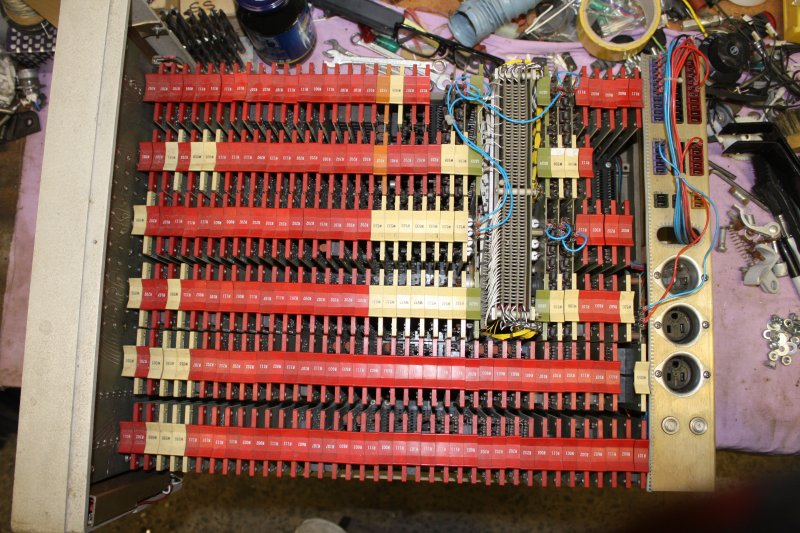
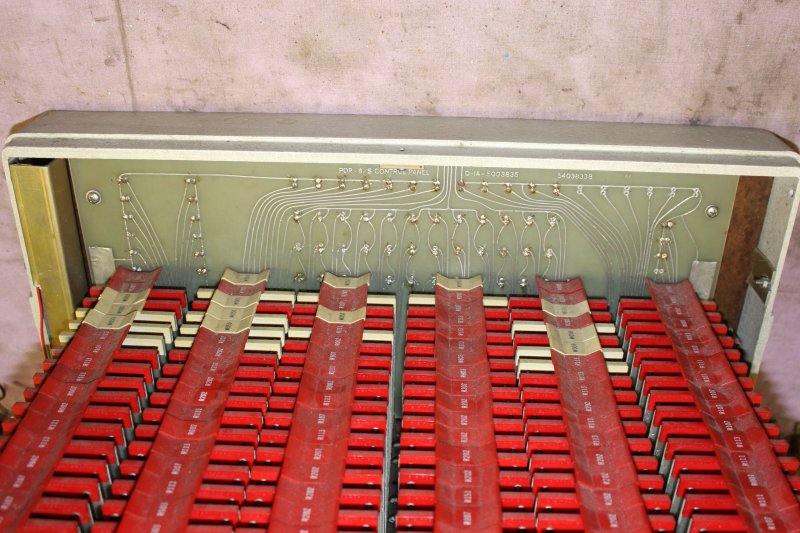
But the worst thing... because of the missing case bottom, that awesome but extremely delicate wire wrapped backplane is seriously unprotected.
Unless the two small mounting blocks at the rear corners are both resting on a hard flat surface, the machine will be sitting on the pins of the wire-wrap matrix.
That's why in this photo of it just out of the box it's on its side. Simply putting it down wrong on the bench risks damaging it.
In the cardboard carton the wire wrap pins were resting on some loose bits of cardboard. Many pins are already bent, but none too much to be straightened. The wire wrapping appears to be intact.
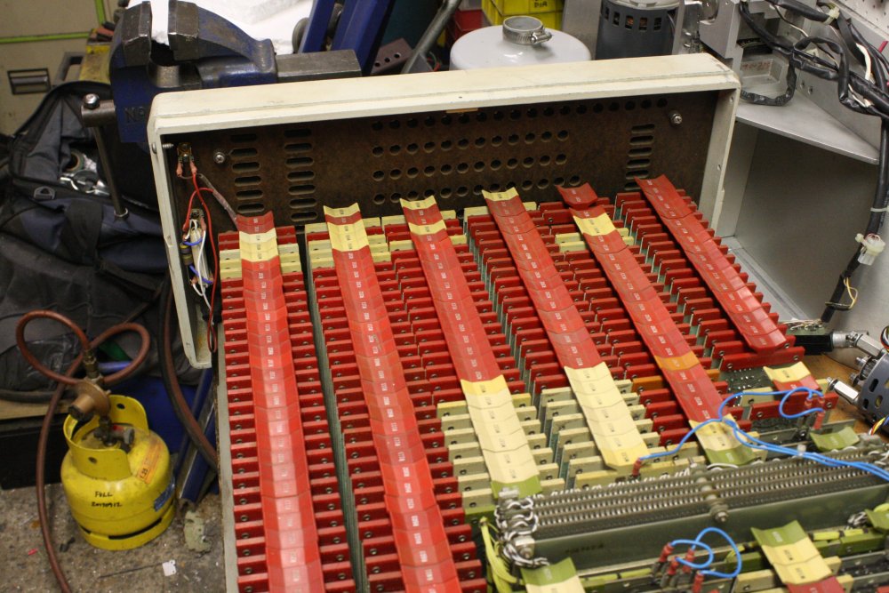
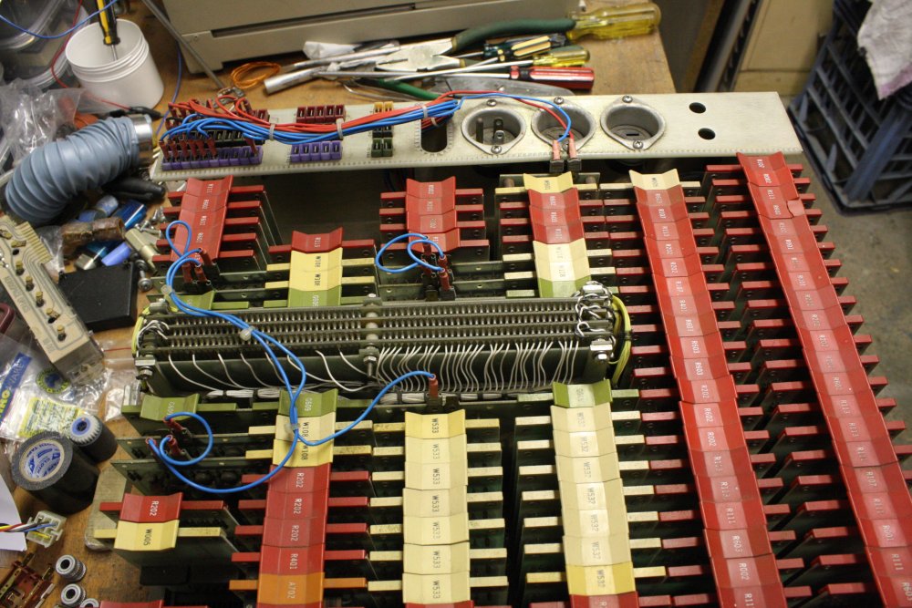
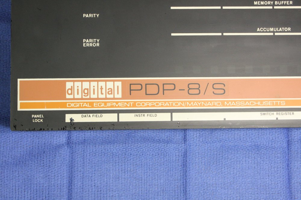
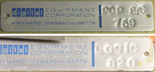
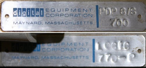 So, now I have a beautiful example of the early Digital Equipment Corporation PDP-8 line of minicomputers. An early and rare one, a PDP-8/S. A computer entirely constructed using plain transistors, resistors, diodes, etc. Not a single integrated circuit anywhere, because they weren't invented yet.
And I cannot just put it back in the box and store it while I get on with current jobs, because the packing is seriously inadequate protection. Bah.
Ironically, this computer is so simple it doesn't implement a stack. Yet it's unavoidably pushed onto my jobs stack, like it or not.
 |
 |
 |
 |
 |
Some more views.
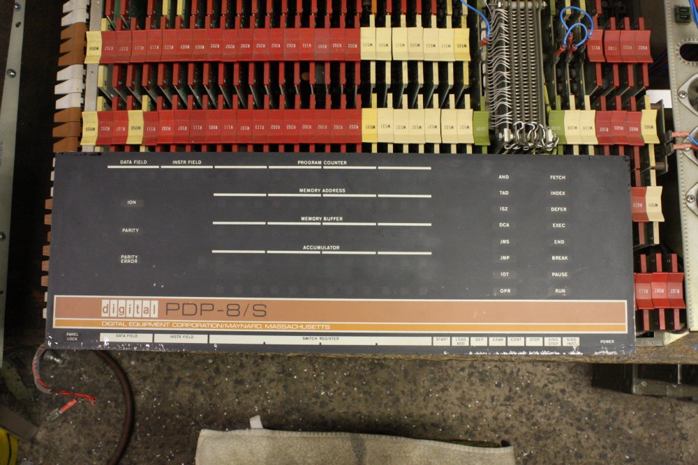
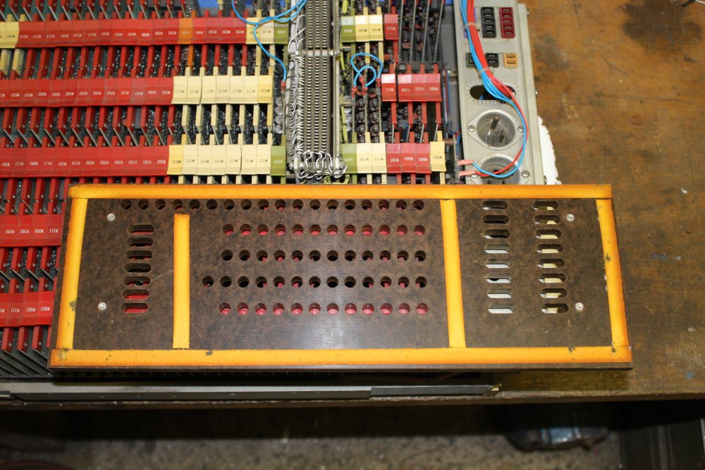
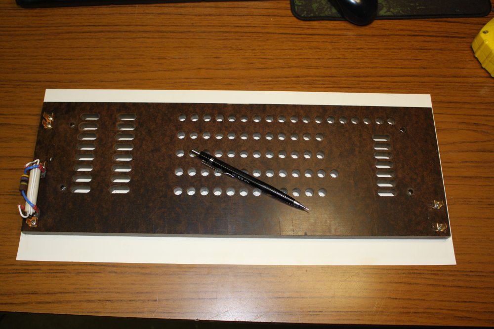
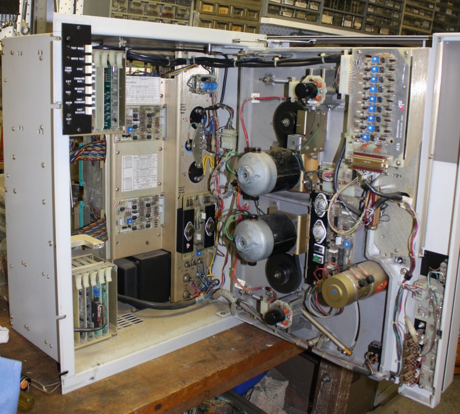
4. Should show the front panel lights PCB, but instead there is only the lamp shroud panel, with holes where the lights would be.
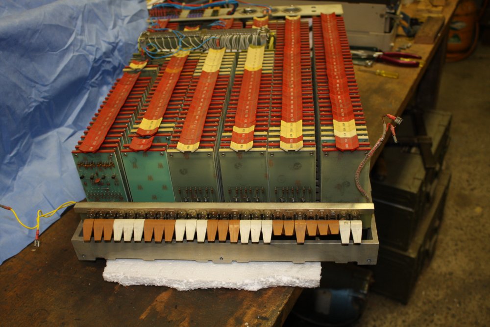
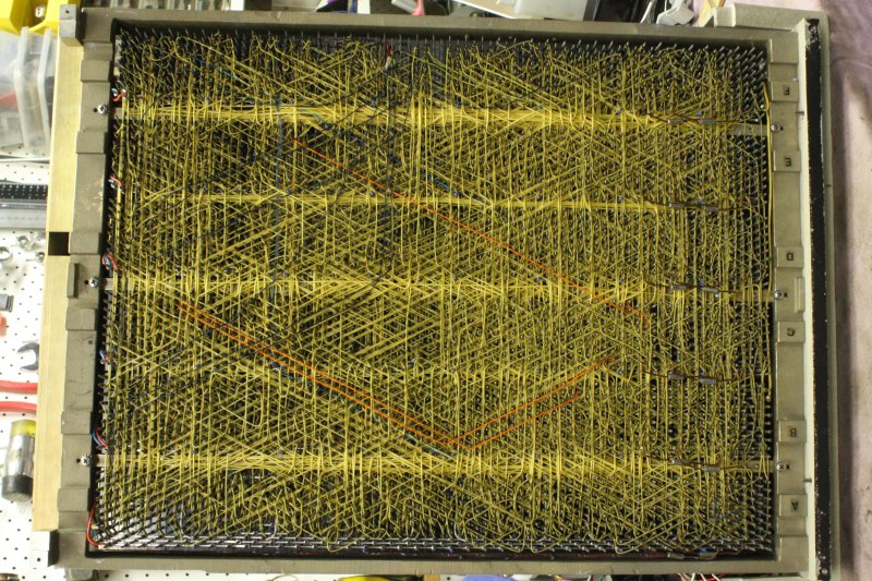
5. The block in the middle is the magnetic core memory module. At rear is where the power supply module should be wired up, but it's completely AWOL.
 |
 |
 |
 |
 |
 |
 |
 |
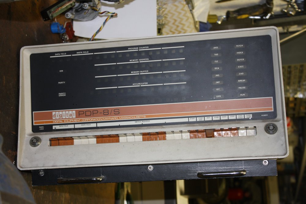
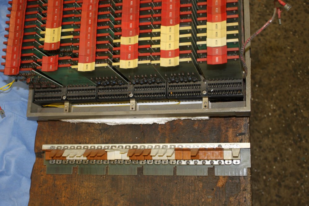
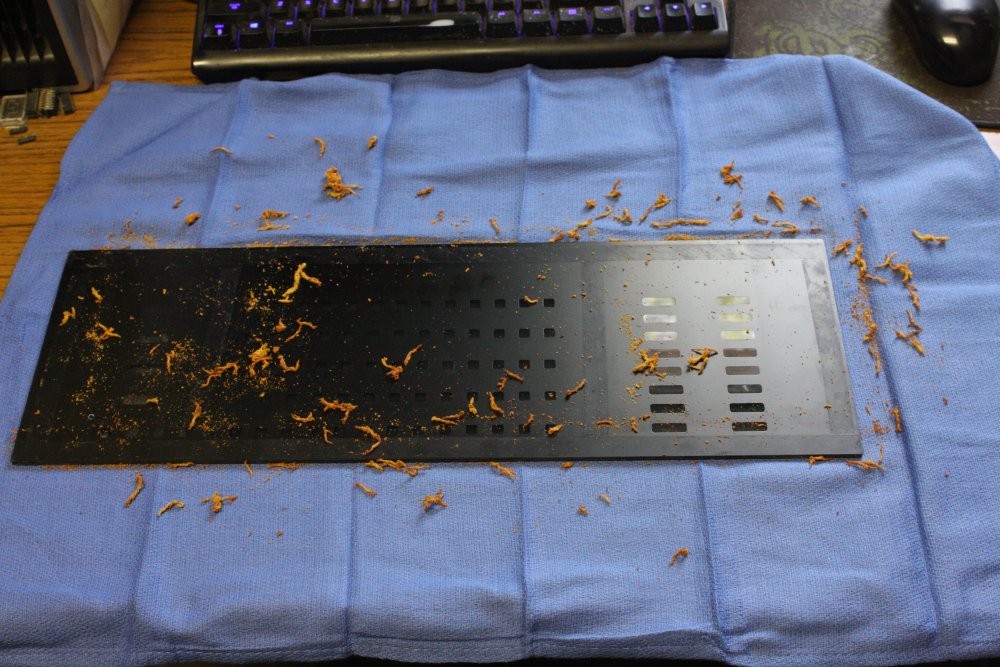
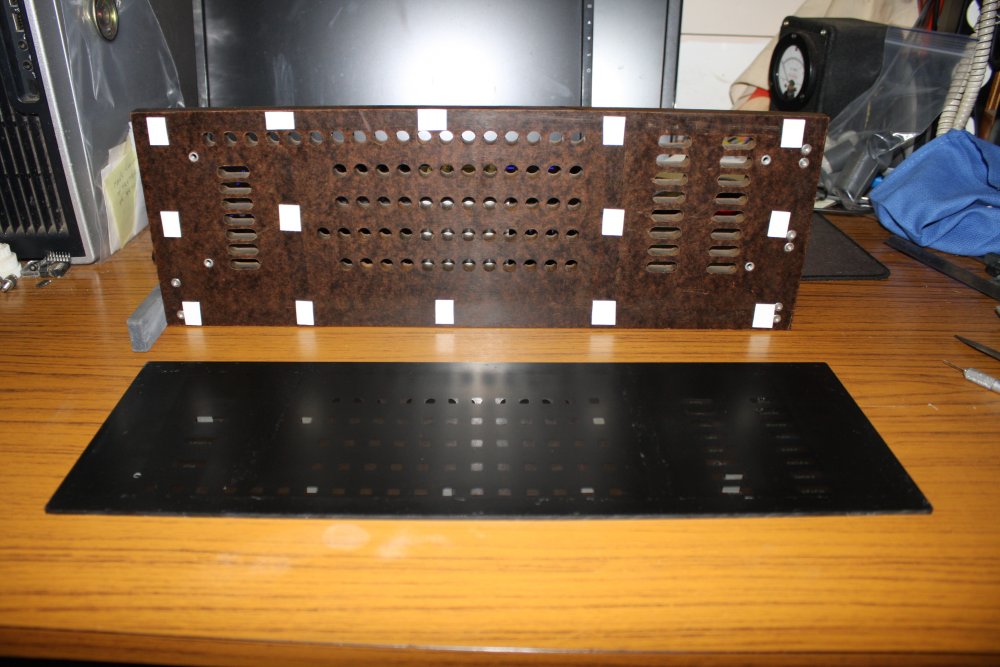
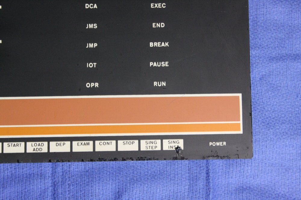
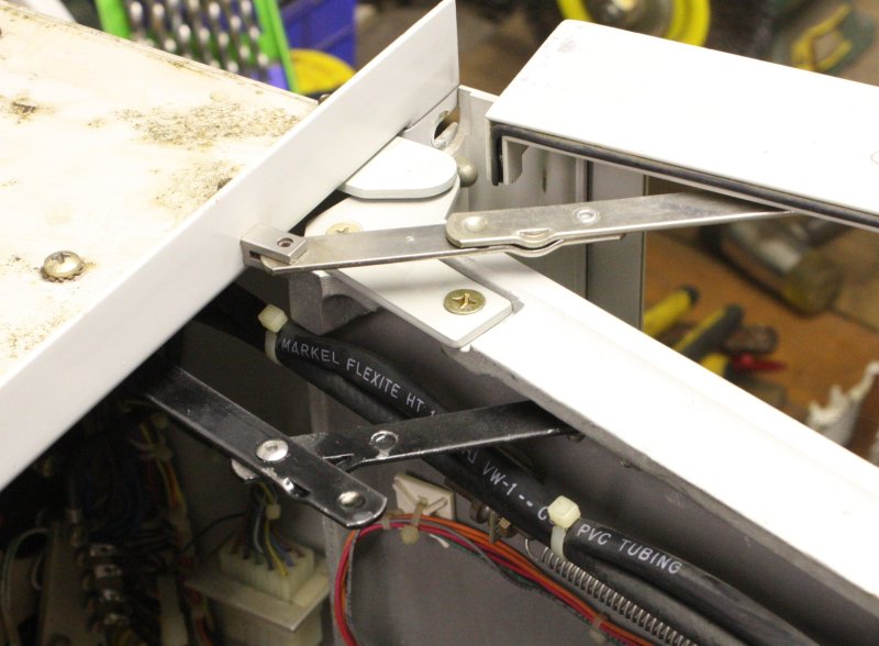
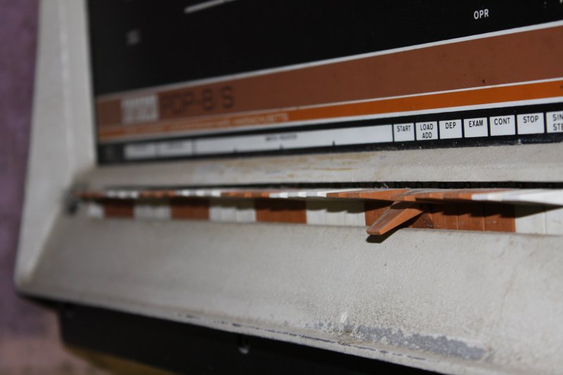
Due to the lights PCB being missing, the front panel fascia and shroud board are loose, and have slid down behind the toggle switches module. Result: the painted legends on the fascia are getting scratched.
I was going to just make the base cover, but this problem has to be fixed now.
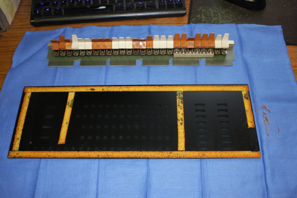
In this series I'm disassembling the front panel.
2. Oh joy, the fascia and lamp shroud were held together with double sided foam tape, that has decayed to crumbly crap.
3. Scratching along the bottom edge of the fascia, due to its sitting loose and rubbing on the pins of the toggle switches module.
 |
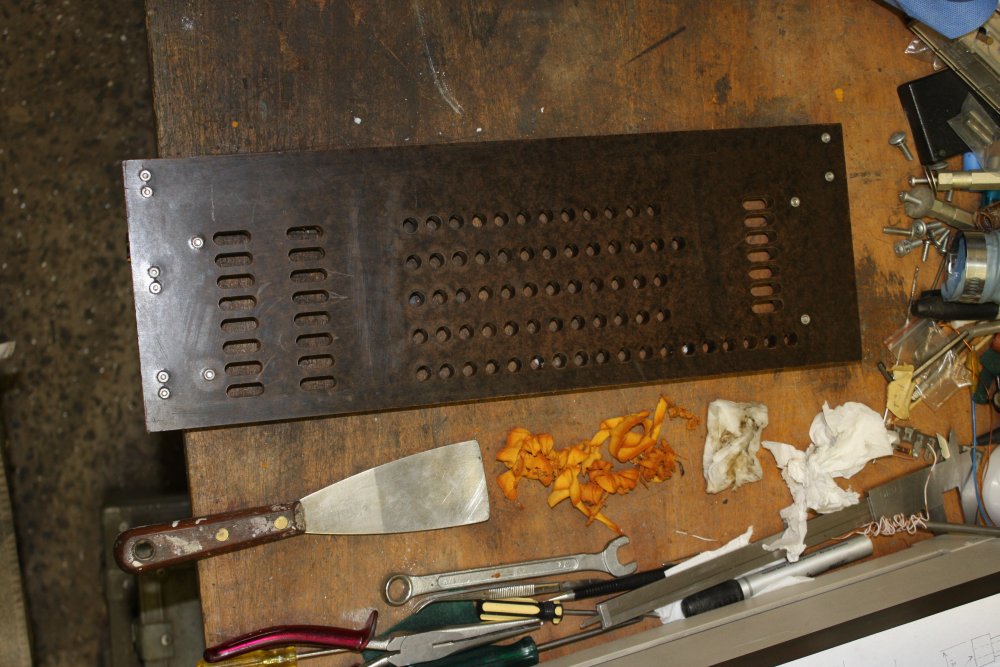 |
Removing the decayed tape from the shroud board is easy, since it's made of a tough high-density fiber board. Scraping and turps...
 |
 |
 |
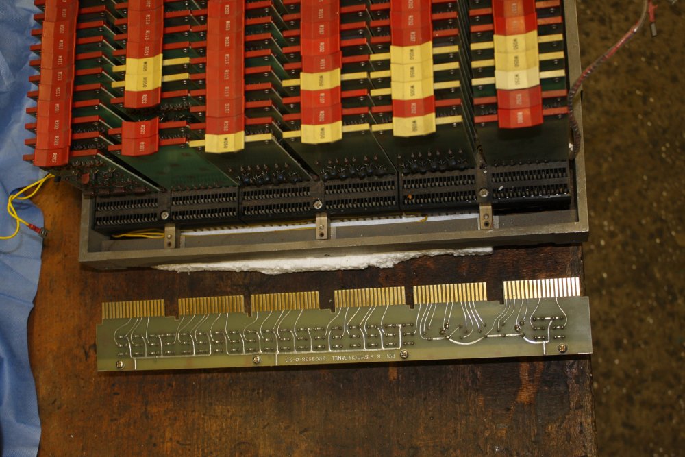 |
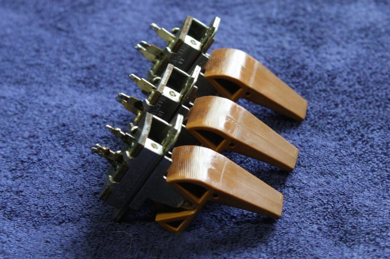
Removing the paddle switches module. It's not screwed in, just relies on the friction of six module connectors. Which is fine, it takes a lot of levered force to pull it out.
 |
 |
 |
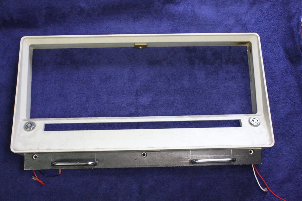
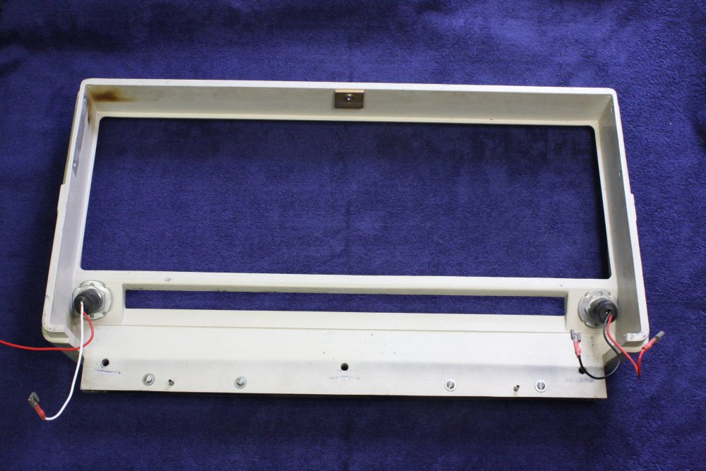
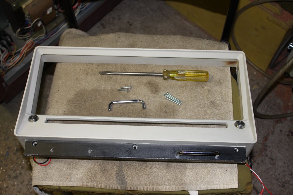
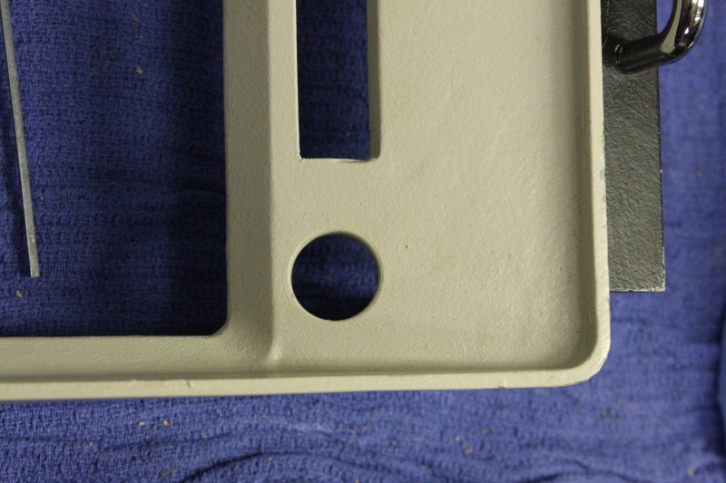
The diecast front panel before cleaning. Those two handles are clearly added by a previous owner. Who left their pencil markings for the holes on the metal, and didn't get the holes quite lined up. The handles were a common cheap small generic type for cupboards, stocked by hardware stores in Australia in the 1980s onwards.
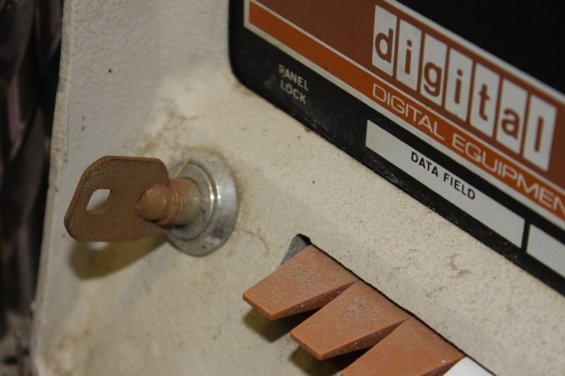
Incidentally, spot the problem. Yeah, the two key switches. 'Power' and 'Panel Lock'. They are both cylinder locks and of course no keys came with the machine. Hopefully they are keyed the same, so this will only cost for one key picking.
3. Yes, those are surgical towels. A friend provided me with a supply, and they are very useful.
 |
 |
 |
 |
 |
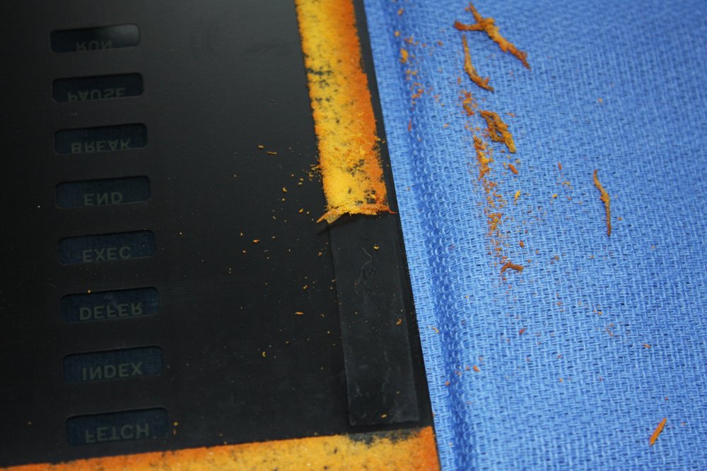
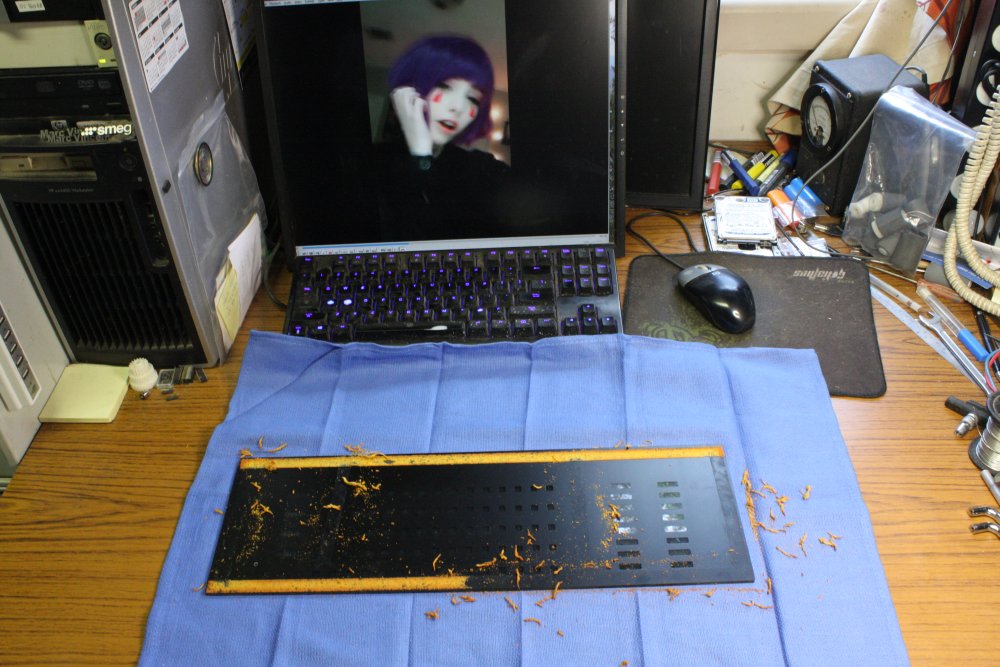
Sigh. Removing the decayed tape from the fascia will be much more difficult than from the shroud board. The fascia has fine painted symbols and coatings on perspex. The rear side with the tape, is painted with the black mask for the blinkenlights mask, so must not be scratched. Pretty much anything may destroy this delicate and irreplaceable thing. Can't warm it up to soften the tape glue. Can't use almost any type of solvent. Can't use a scraper...
The only way is to gently, slowly, rub it off with a finger tip. The glue is tough, pressing hard enough hurts. OK, this is going to be tedious and literally painful. It needs a theme song, so pic 3. Bonbibonkers, Hard Times.
 |
 |
 |
 |
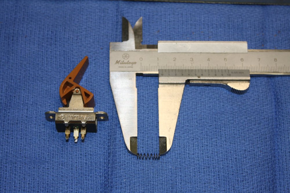 |
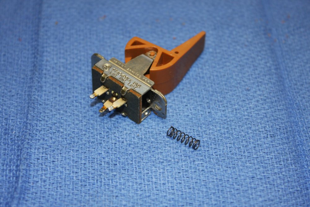
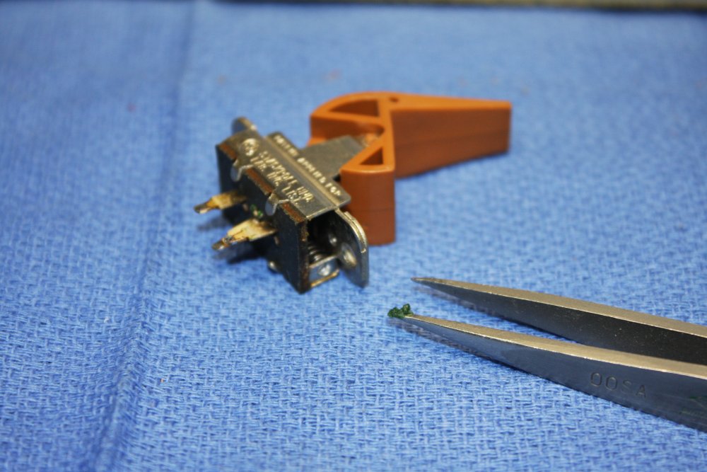
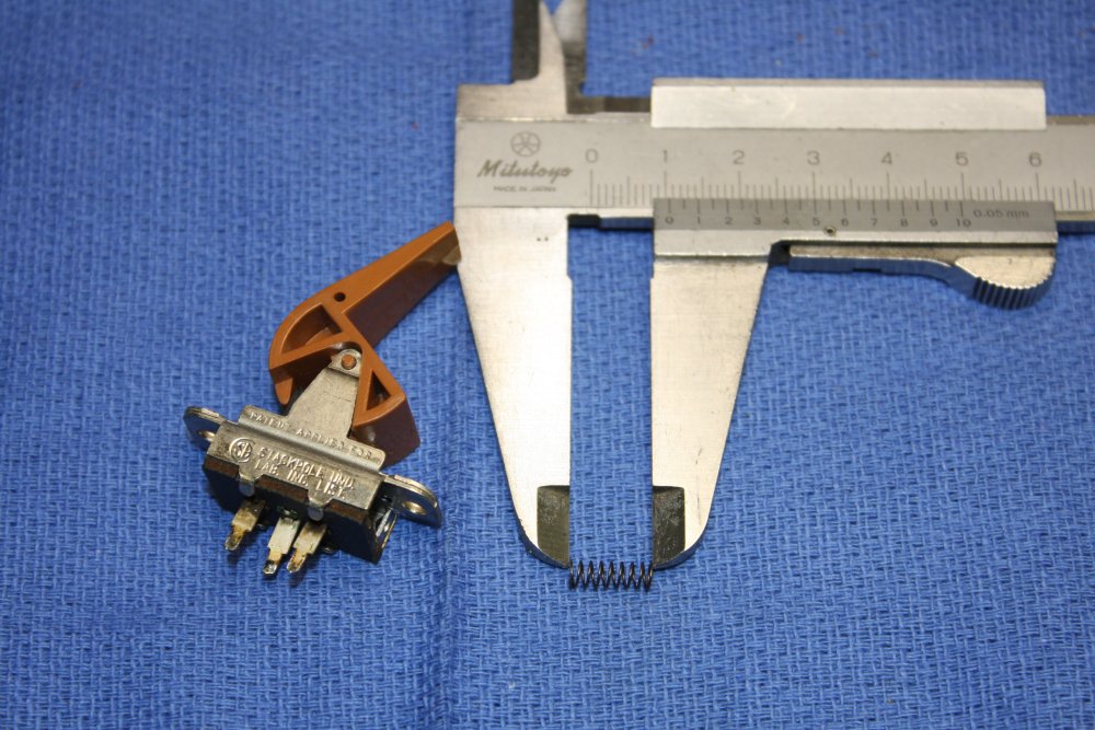
Then the paddle switches. Cleaned the whole assembly. Some of them have spring returns, and with a couple of those the springs are a bit weak and don't return the paddle all the way. Pull the springs out with fine tweezers, stretch slightly, replace. Also add a little lithium grease. Switches now feel crispy.
The 'soft' springs were about 10mm long. Stretched to 12mm made all the difference.
 |
 |
 |
Resoldering them in, clean with IPA, go through all of them testing the contacts are OK. A few were a bit iffy, cleaned those with IPA.
A funny thing I noticed during this. Most of the switches have 6 pins, as if they are double pole double throw. The PCB is wired as if there are two contacts per switch, wired in parallel for reliability. As you'd expect.
But... ha ha, the switch manufacturer gyped DEC or something. All these 'double pole' slider switches have only one of the two internal bridging contacts installed. And which one, is random. Bizarre.
 |
 |
 |
 |
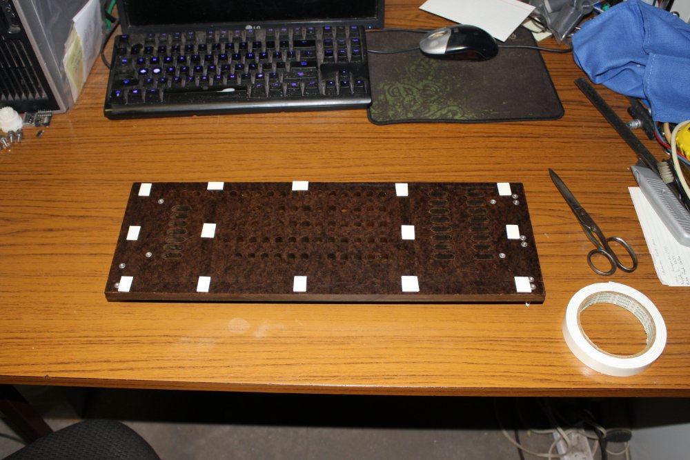
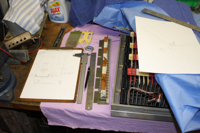
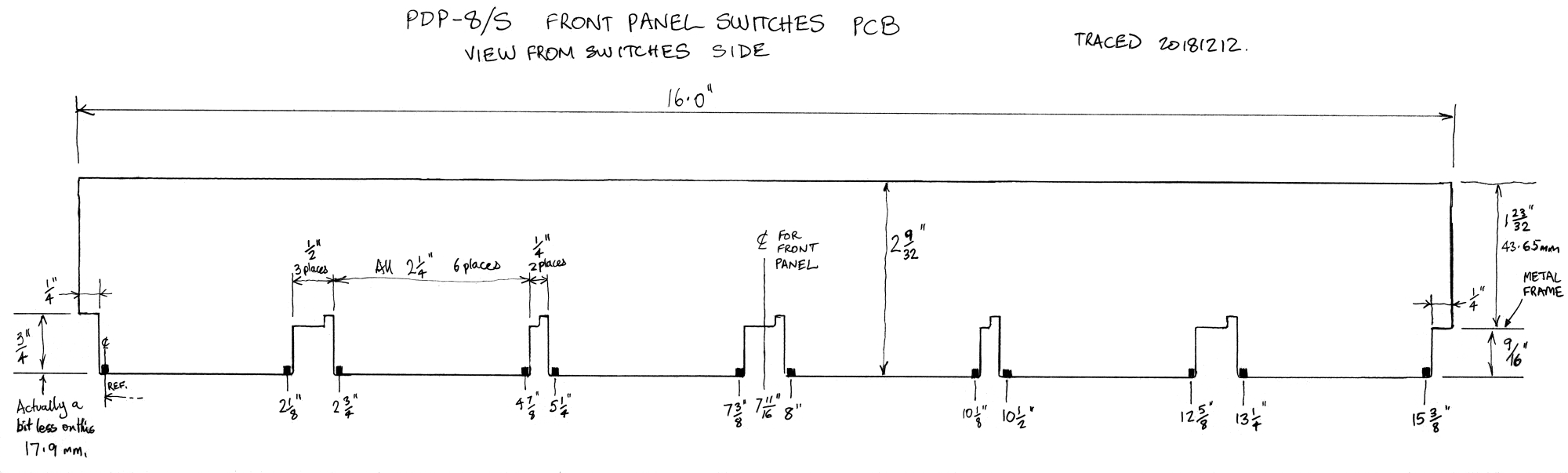
I'll want to reassemble this, but may also have to make a replacement lamps PCB. So in Pic 1 making a tracing of the lamps shroud board, for the spacings. (Also measured the critical dimensions.)
2 - 4. Reattaching the fascia with new double sided tape. Not all over like the original, in case I need to separate them again. To keep dust out, later I'll add some kapton tape along the edges.
 |
 |
 |
 |
Not sure what to do about the scratched paint in a couple of places. Maybe nothing. Will have to experiment on something else before attempting anything with this.
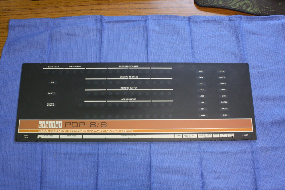
Pic 3 is a rough stitch of scans of the fascia. Rushing, I messed up the colour adjust irreversibly, so need to re-stitch from the originals before posterizing the colours. Anyway here it is for now.
Pic 4. Preparing to make the protective base. I've bought most of the metal sections and a sheet of clear acrylic. But there's one issue remaining. What to do about these extremely unauthentic looking added chrome handles? The heads of their mounting screws are in the way, for how the original base cover obviously attached. Which makes them in the way for a new cover too.
So, do I keep the handles and countersink the heads down into the inner surface of the thick diecast panel?
Alternatively discard the handles, plug the holes, sand and repaint that lower piece black, so it's back to the original appearance?
 |
 |
 |
 |
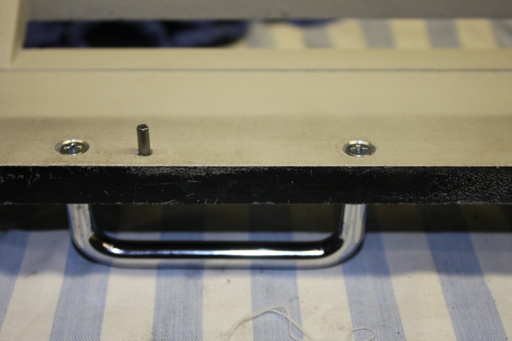
1. Countersunk the screw holes for the handles. Plus here's an original roll pin, that's obviously part of the original lower case mounting setup.
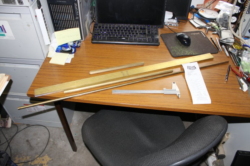
2. Cutting off bits from bar stock that's too big for my cramped workspace.
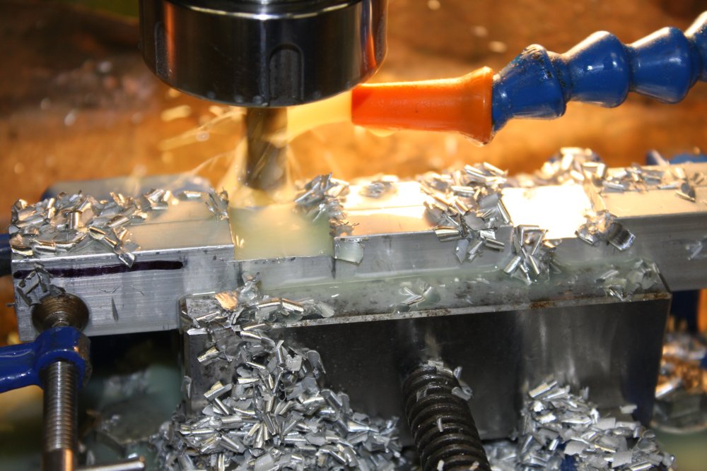
3, 4. Rough milling of the base end bars, to clear the castellations of the PDP-8/S cast metal frame underside.
 |
 |
 |
 |
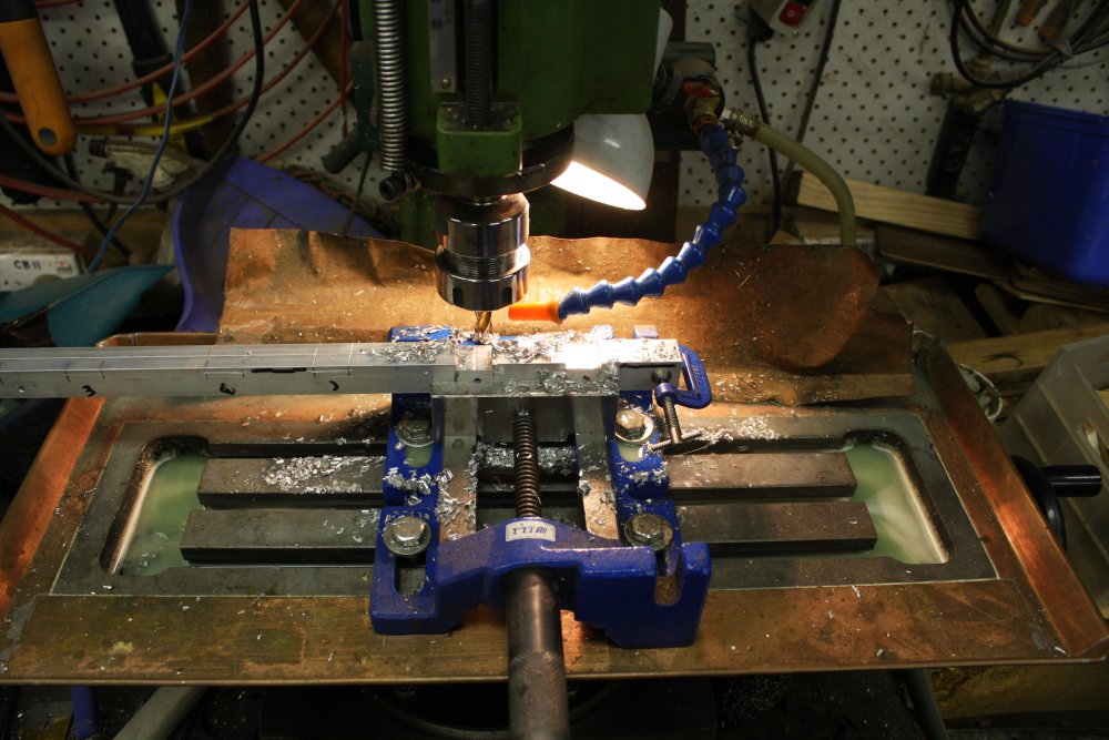
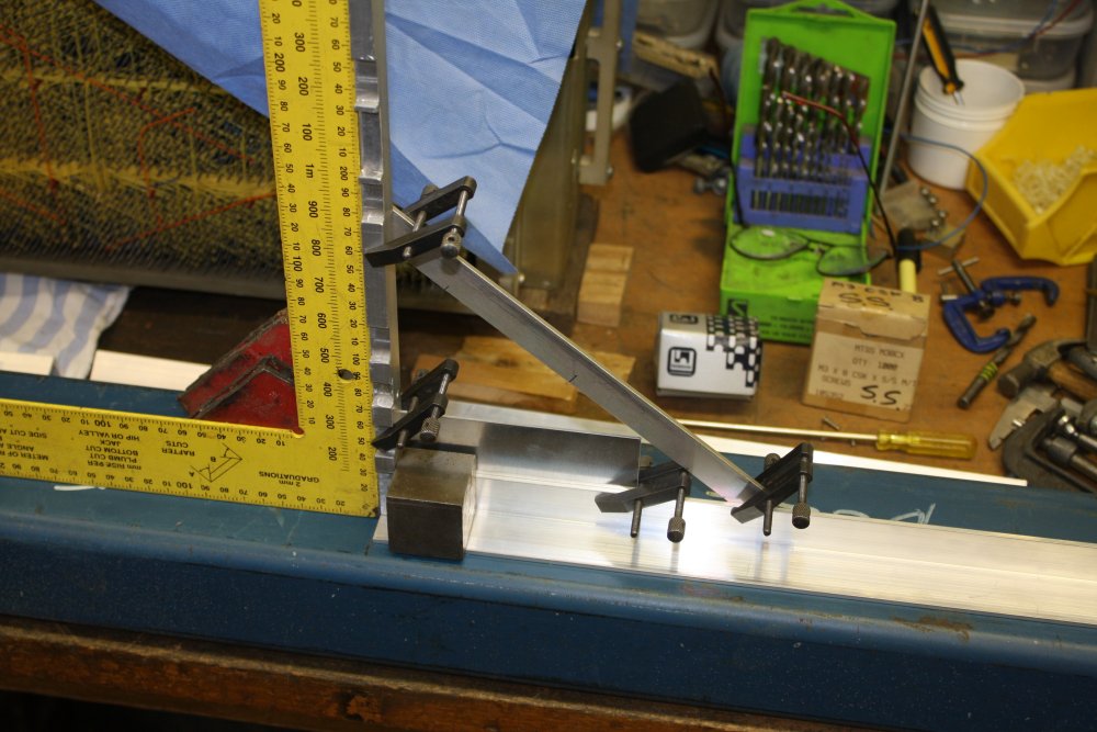
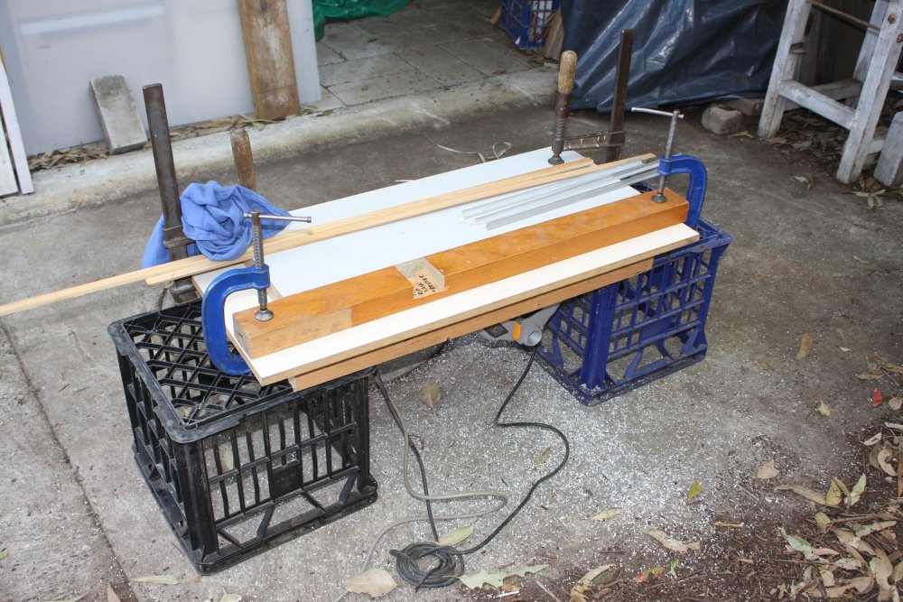
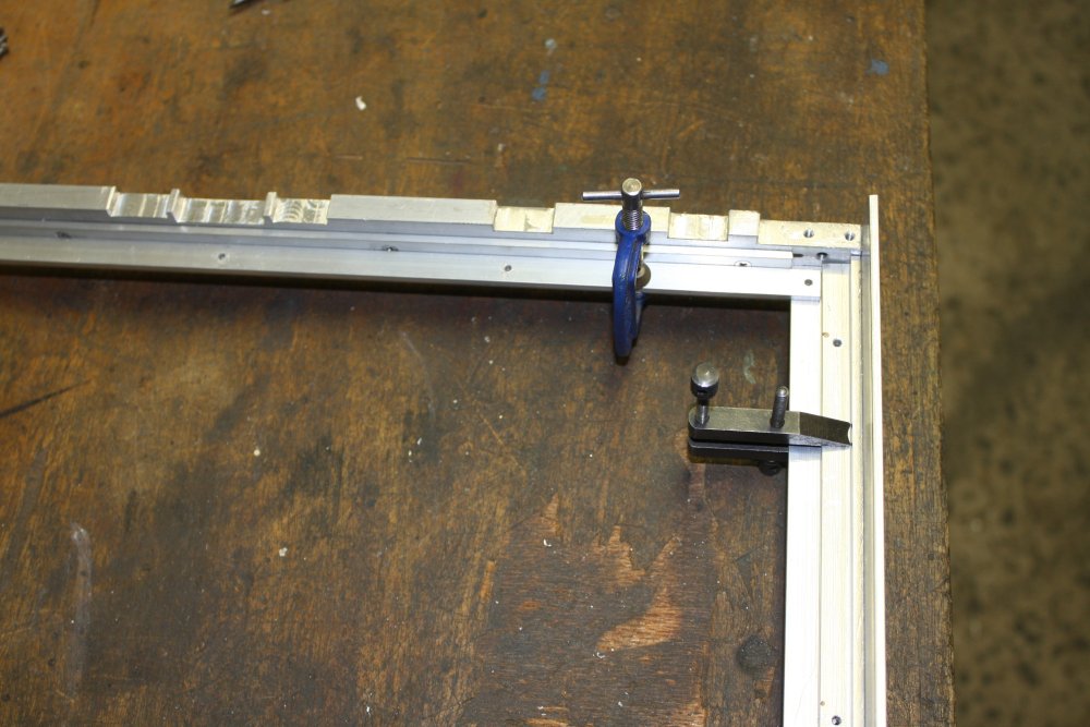
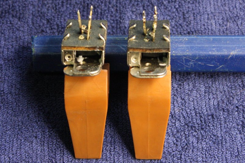
Drilling the holes for the corner screws of this under-frame, has to be pretty precise. I used a drill template and a jig for setting the corner joints to exactly 90° when clamping them for drilling. The big blue steel beam is just a reference flat, since my bench has a bit of a bow. Also the steel base allows using magnetic clamps to hold stuff.
 |
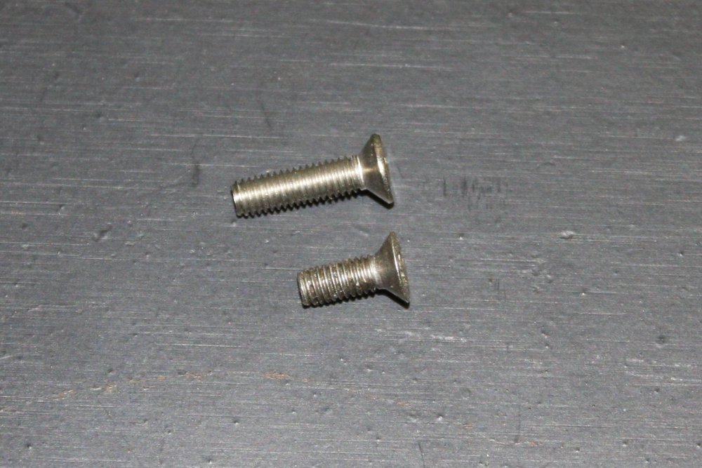 |
The base frame so far. The corner frame screws aren't countersunk in yet, because I found my box of M3 12mm CSK screws have malformed heads. The short screw head is correct. Will have to go buy a box of better ones.
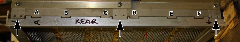
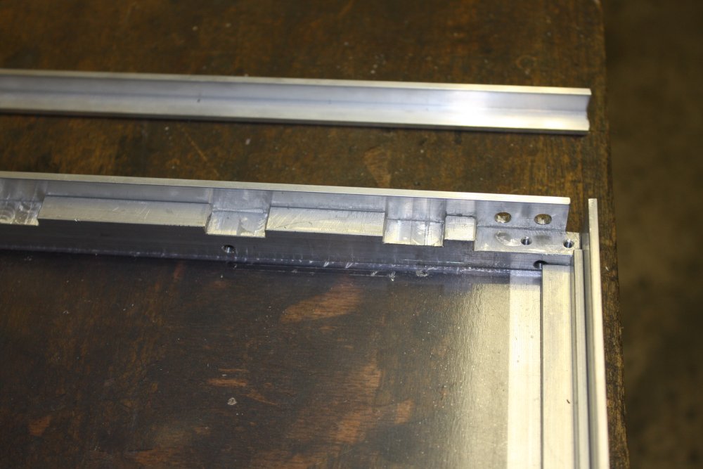
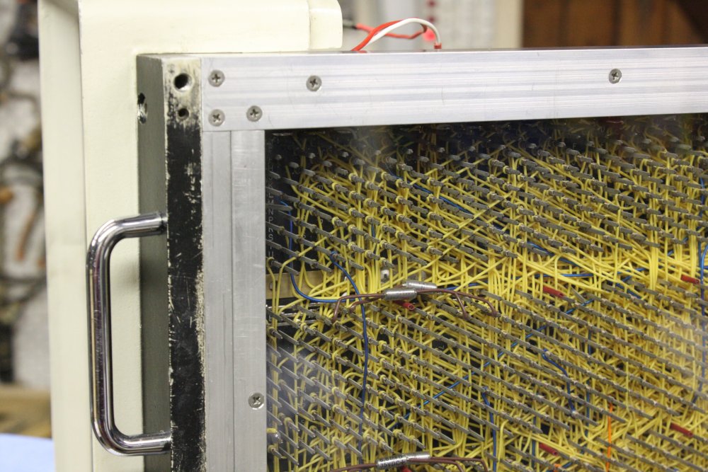
A visual note for anyone else who has a PDP-8/S, and might be considering making a similar base. At the machine front, the castellations labelled A through F, have stick-on decals with those letters. They are the grid references for the wire-wrap panel. If this frame touched the decals it would rub them off.
And so, the base cover frame end pieces are milled so they only contact the PDP-8 frame at the points arrowed. Apart from changing the screws for those user-mod front handles from round head to countersunk, there are no modifications to the PDP-8/S for this base cover. It attaches only via existing pins and threaded holes.
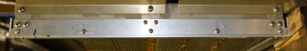
Here's the same view, a bit later with a rear securing strip in place.
 |
 |
 |
 |
 |
 |
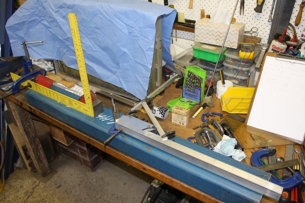
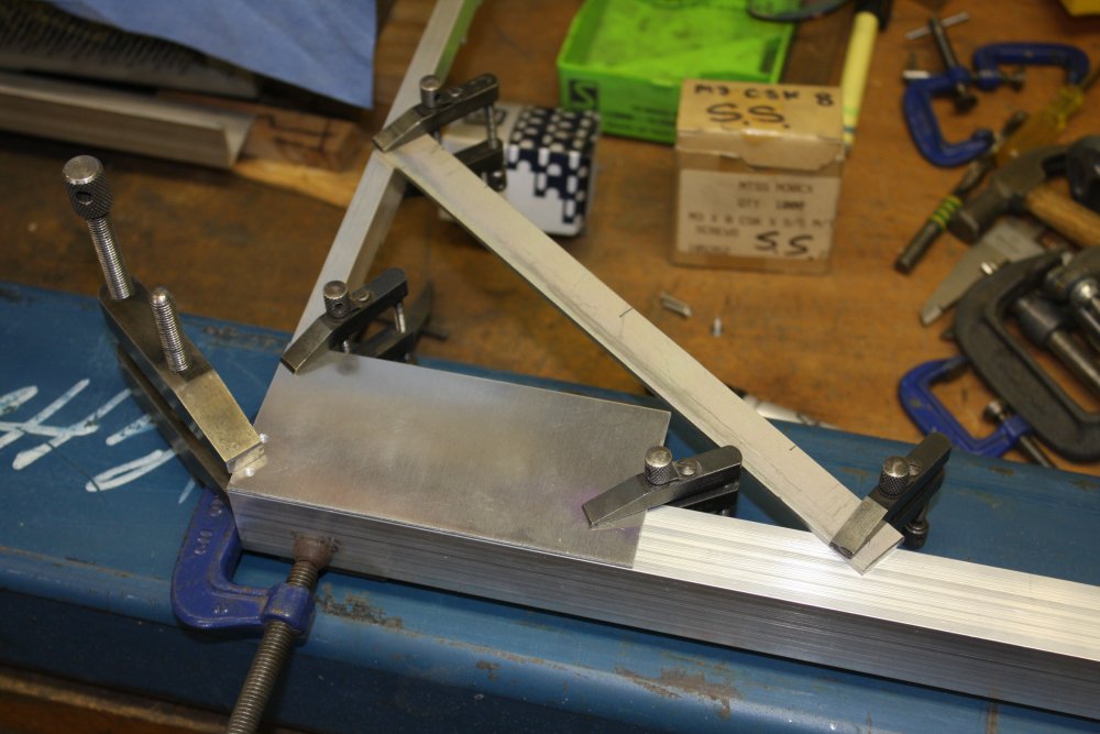
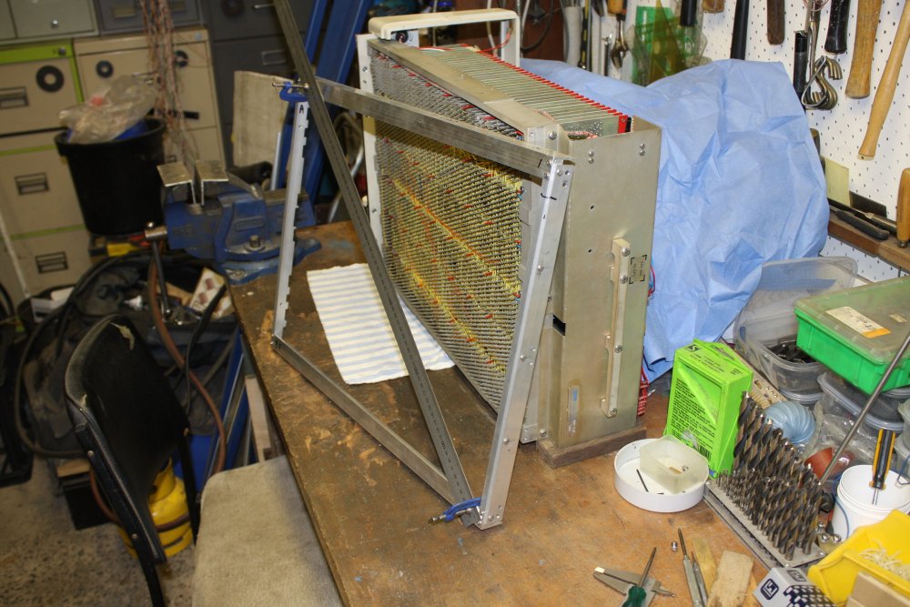
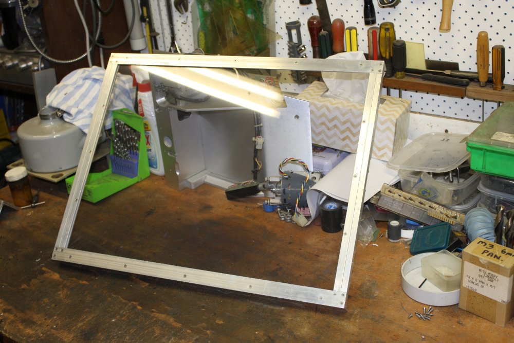
1. The frame removed from the PDP-8, with a diagonal brace to keep it the same shape as fits the PDP-8 frame. (That might be exactly square, or might not. Easiest to just keep it 'same.') Since next is to mark and cut the clear plastic sheet to fit it.
2. Heh. I moved the PDP-8 off the bench and found this underneath, fallen out of somewhere in the machine. This is an old-style Tektronix oscilloscope probe ground clip. Which had been lodged inside the PDP for a long time. Bet there's a funny story behind that.
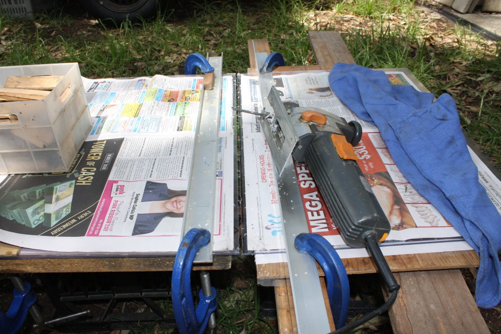
3. Cutting the plastic sheet. I was nervous about this, since in the past when I cut perspex it sometimes cracked. But this stuff ('acrylic') seems to be much easier to cut. Used a brand new, nice and sharp wood saw blade (with tooth pitch less than the sheet's 3mm thickness) in the jig saw. Set the blade speed quite slow, and sawed slowly. It leaves a very clean cut. The sheet still has its protective films, but I added more anti-scratch protection in the form of newspapers. One of those guides (on the left) is an edge to slide the Jigsaw along; the other is just there to hold down the paper. It was a windy day, and besides the saw would push the paper along without a holddown.
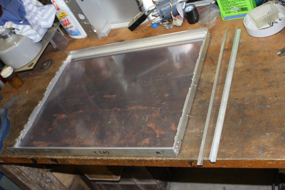
4. First view of the frame with the plastic in place. But not secured yet. It looks a little frosted due to the anti-scratch films still attached.
5. Sigh. I hate when that happens. Here I have the frame with plastic sheet on the bench, preparing to make and mount the retaining strips. And the moment I looked at it like this, I thought of a better way I should have done the retaining of the plastic sheet.
6. I could have milled a slot along the inside edges of the solid end bars, to take the edge of the plastic sheet. A 3mm wide, 3mm deep slot would have worked fine. A bit of trouble to set up to do the slot cutting, since I don't have a collet for a 3mm routing bit. And my table saw's blade is 2.5mm wide, not 3mm. But otoh, the way I'd planned to do this (with small 'L' sections, tapped screws, etc), is also fiddly.
It's too late now, since for the better way the clear sheet needs to be a few mm longer, but it's already cut. Typical. There's that tradeoff again, between 'getting things done', vs spending days thinking about doing it. Which often still ends up with a better way becoming apparent during the actual build.
Anyway...
 |
 |
 |
 |
 |
 |
1. Some small L sections needed trimming a few mm off one leg of the L. Here's my home-made rip saw (normally for wood) getting used to do that. Making a lot of aluminium chips to sweep up later. The saw blade is down in a slot between the two clamped-down guides. The bit of metal gets pushed through the slot using sacrificial sticks of wood. Crude but it works.
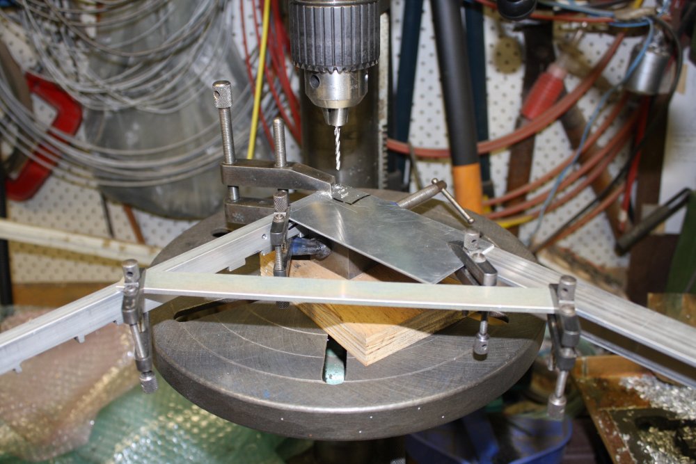
2. As usual, transfer drilling. Center punch the holes on one internal strip, clamp it to its identical piece, drill them both. Then clamp those to the frame and drill through the holes. No misaligned holes! Those were all done with a 2.5 mm drill, since some of these will be tapped. Later drill out the clearance holes to 3mm. And with the clear acrylic sheet, the same holes drilled to 3.5 mm, to give a bit of extra clearance.
I also letter-punched all the frame pieces with orientation marks.
3. The frame and clear sheet, done! Well, except that all the M3 screws are 8mm long but have to be changed to 10mm when I buy a box of those on Monday. (Later: Done. Ha, there are 36 of these screws in this cover.)
The acrylic without the protective films is very clear (reflection is the ceiling light) but sure does develop a static charge and attract dust. So, how static sensitive is pre-IC computer circuitry? We'll find out.
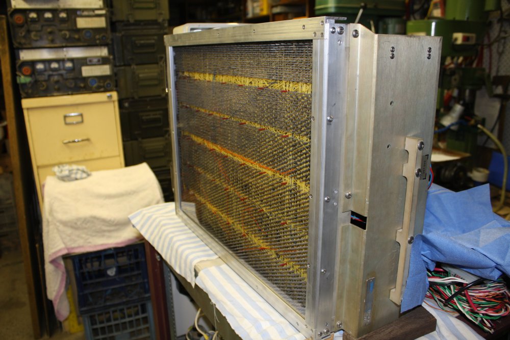
4 - 6. Views of the base cover mounted on the PDP-8/S.
Not to mention returning to some other projects.
There will be more here on this machine, but probably not for a while.
Once it's certain the machine can be got going again, I'll look into having the aluminium of this windowed base anodized. Black I suppose. It could also do with stick-on felt or cork feet. Then there's the question of what to do about a case top. Some kind of dust cover at least. A hot formed clear plastic case perhaps?
The front panel casting fits in the front recess of a standard 19" rack, but not in the equipment opening. The body (including the new base) does fit. A top cover that fits in a rack would have to be narrower than the front casting.
Unfortunately the original rack mount sliding rails (lost), with a locking pivot point on the PDP-8/S cast frame, requires the machine to be completely bare — no top or bottom cover. That was for ease of access for servicing and was OK back then. But now the machine is a rare antique, it's not OK. How I'm going to solve this, is still an unknown.
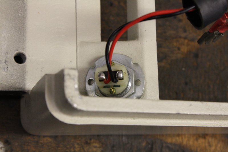
The PDP-8/S has two keyed switches on the front panel.
The LH one is 'Panel lock', the RH one is Power on/off.
They are identical looking Ace cylinder locks. Presumably they will both use the same key.
Naturally with this PDP-8/S no keys came with the machine. Long ago lost.
To get the machine running, I need to make keys. Because this is a museum piece it's best to retain the original locks, undamaged. This means the locks have to be picked.
Not so easy. I can pick standard locks (not very well), but cylinder locks are another matter. The easiest path should be to take the locks to a locksmith to pick and make keys.
I first tried taking the front panel (with both locks) to Bankstown City Locksiths on Tues 20181113. Leaving the panel with them made me nervous, but I explained it was a high value antique, and they understood the need to be careful and why picking the lock rather than opening it (involves cutting) or replacing it with a new keyswitch, was required.
They quoted $50 to pick it and make two keys. Next day I phoned about progress. The guy had tried briefly but failed. One of their two locksmiths was away for a week, so the one guy working was very busy, couldn't say when he'd try again. I went and got the panel back, saying I'd wait till they had more time.
That week I considered what would be needed to pick it myself. I'd have to make a tool, which would involve some fine machining, plus some hurdles:
 |
 |
 |
 |
 |
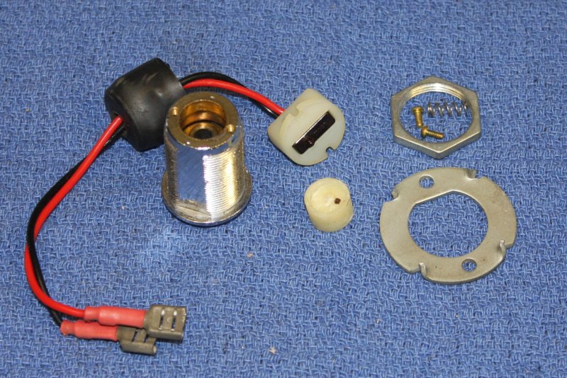
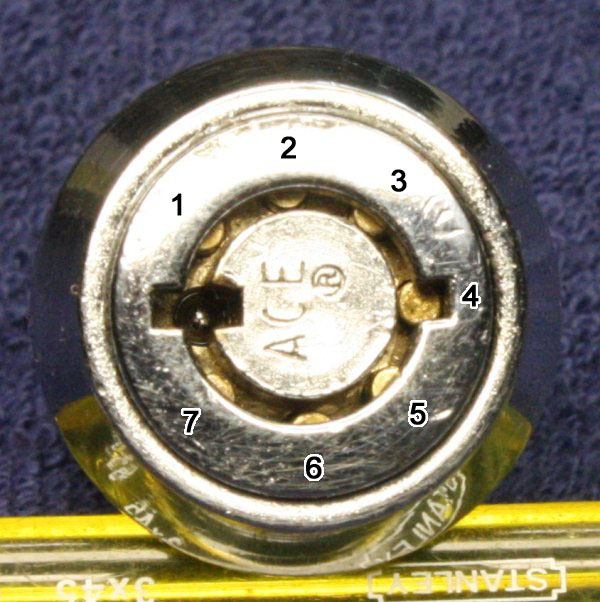
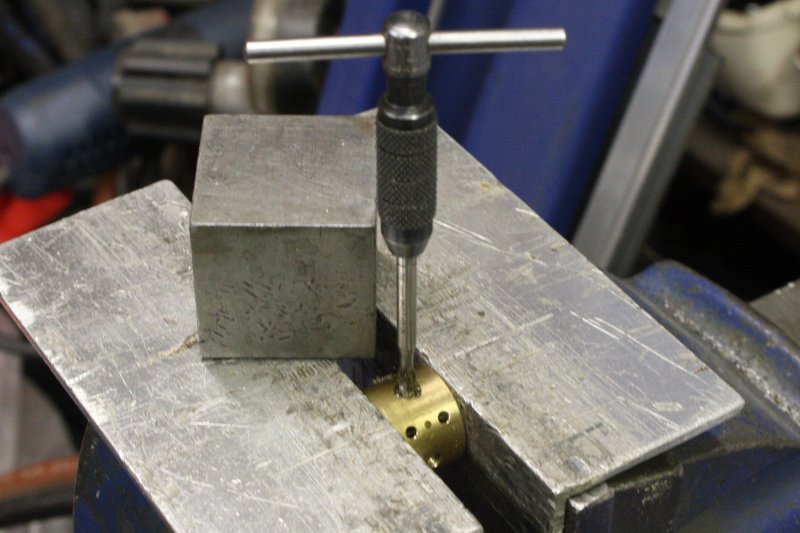
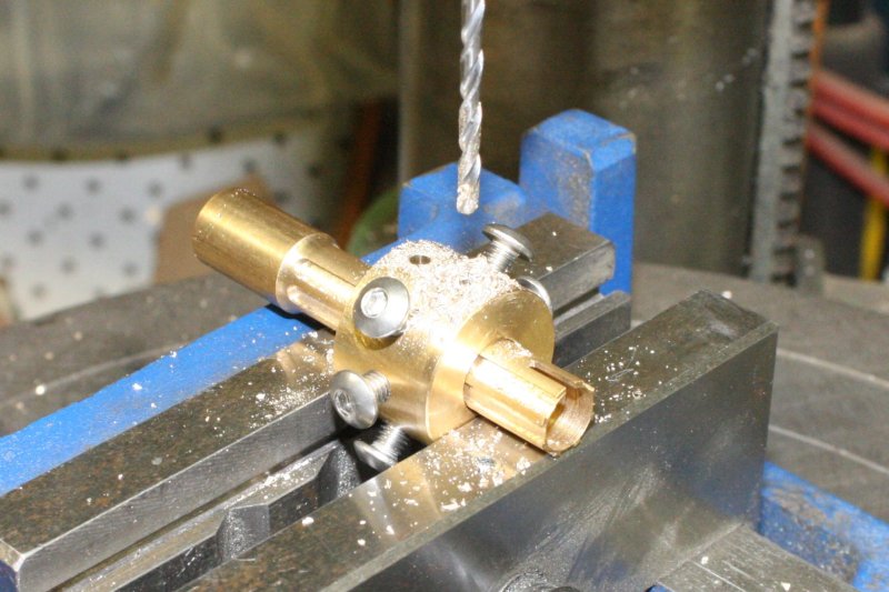
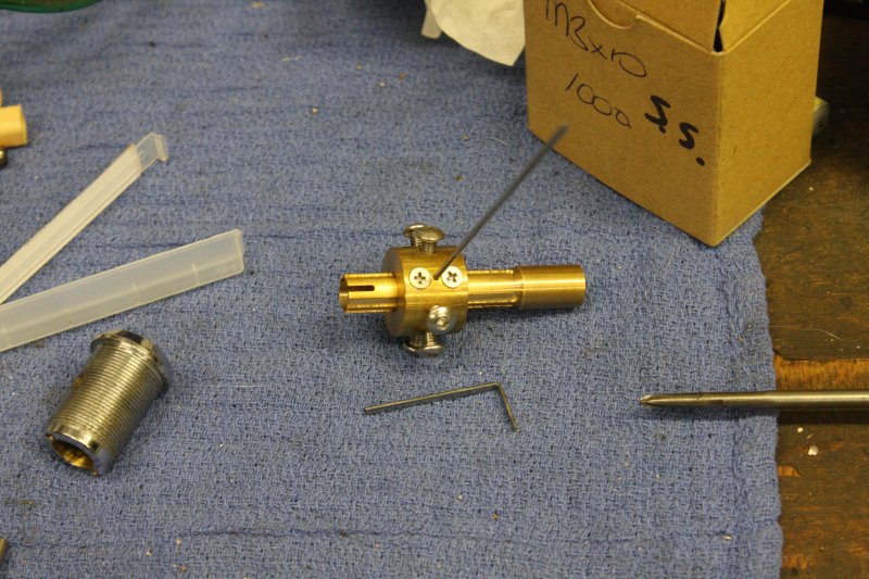
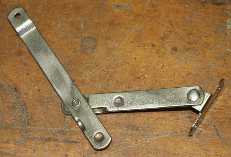
As part of that consideration I removed one of the locks from the panel, and took off the switch part, giving me just the lock cylinder to examine. It's interesting, as there's something a bit unusual about it. There are the usual 6 live pins that push down onto the springs nicely, no sign of sticking.
But there's also a 7th pin, that is loose (no spring) and sits not-quite flush with the key end mating surface.
It's the same in both locks, so not something 'broken'. What is this?
Thinking about it, visualizing the lock internals and how a typical picking process would work, I figured out what it's for. A rather clever anti-tamper mechanism, that would trap the unwary with a jammed lock if they do things wrong. It also prevents a standard lock-pick tool from sitting down fully in the lock. Hmm...
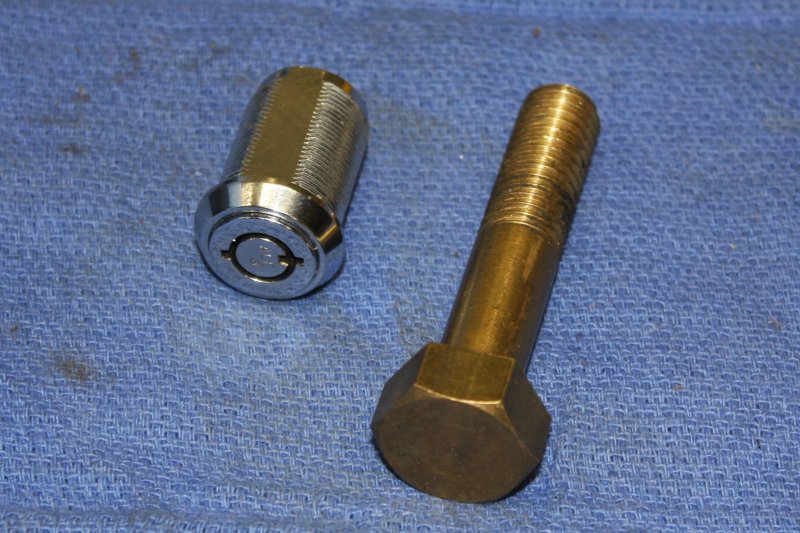
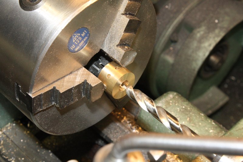
I made a simple start on the pick, machining the brass bolt head to round. But thinking about the amount of work involved I decided I'd rather just wait till next week and pay the $50. Also a friend recommended an 'old locksmith wizard' he knew, but that guy is down in Narellan (long drive) and can't be contacted via the phone numbers I was given. Potentially a backup option.
So, just waiting...
In the meantime, other stuff:
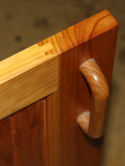 I'd made some back in 2006 (while the workshop was still one large open space) but stopped when I found the fine wood dust was getting into all my stored electronics gear despite dust sheets.
Then there was a sequence of marriage dramas, health and land rezoning issues that kept pushing building projects down the queue. Now I'm gathering all this project's bits I'd stored back then, and happy to find I didn't lose any parts. Setting up the wood working gear to complete the cupboard doors. 7 like this, and 12 smaller ones with glass inlay.
This time without getting fine wood dust all through the building. Can do now, the room has a door and I have a vacuum dust catcher thingy.
Ah, the building works. Quite a few articles to write up there.
On Wed 20181121 I took the bare lock cylinder back to Bankstown Locksmiths and left it with them since they now have both guys working. Also gave them a link to this PDP-8/S blog page, since they seemed interested.
Phoned up on Thursday — "no success yet."
Late Friday afternoon I phoned again. "Still not picked, have tried several times, we think there is a fault with the lock, one of the pins seems to have a broken spring." He kept trying to tell me this; I said I'll come round now and you can show me.
Got there about half an hour before they closed. Took the front panel with the 2nd lock in place to demonstrate both locks have that 'dead' pin. He again started talking about the 'broken pin/spring." I stopped him, showed him the 2nd lock is the same, explained how that odd pin functions. He reluctantly got it. I found it pretty amusing to be explaining this to a locksmith. He fetched out the tool he'd been using to attempt picking the lock, and showed me how he used it.
More 'hmmm...' He claims with this tool it's supposed to simply press into the lock opening, and the feeler rods 'just automatically' find the correct depth for each pin, then you turn the tool and the lock opens.
But but but... that's not possible! Maybe for locks with very poor manufacturing tollerance, it's possible? He claims he's used this tool a lot, and it does work. Very odd. The only way I can see that working, is if modern cylinder locks are deliberately manufactured with slight but progressive mismatches in the radial alignments of the inner holes relative to the outer holes. So just one pin at a time would get stopped as the pin sheer planes lined up.
Maybe nowadays cylinder locks are manufactured like that to make life easier for locksmiths? In a world in which governments hate individuals having access to strong encryption I can imagine there also being 'offical encouragement' for locks to have deliberately designed-in weaknesses too.
But this lock was made in the mid 1960's. The PDP-8/S probably cost more than a house at the time, and some machines would be used for work requiring high security. So DEC probably bought the best pick-proof locks they could. Machined accurately to high precision, no deliberate tollerance slack to enable auto-picking. He's likely never encounted a very high quality old cylinder lock before, hence why he's mystified that his tool doesn't work on this lock.
Anyway, he gives up. Suggests cutting the securing pin out, or replacing the locks with new ones. I politely decline, go home with the lock.
That evening when I see my friend I mention this, and not being able to contact the guy he recommended. He says it's always hard to contact his old locksmith acquaintance, he just goes to see him, usually on Saturday mornings.
Next day (Saturday) I take the long drive down to Narellan, with the name of the shop where the guy works. Turns out 'Narellan Town Center' is a quite enormous shopping center. Really vast, with sections both sides of the main road. My knowing just a shop number doesn't help pick a side, so I drive into a randomly chosen entrance to the equally vast parking caverns. To make it simpler to find my car again I choose an outside 'overflow' parking area in a neaby field (also quite full, but I can navigate by memory outdoors; in caverns not so much.)
Walk back into the shopping center, take the first entrance I find. 2 escalator levels up, walk into a food hall. Wander a short distance looking for a help desk or site map. No luck. Find a small 'keys cut' kiosk, wait to ask that guy.
Turns out that is the kiosk and the guy I'm after. Cool, that part was much easier than expected.
I show him the panel and locks, explain the objectives. And he does know his stuff. Knows what that extra pin is for and how it works.
 The bad news is, he thinks these locks would be very hard to pick, and recommends cutting the locating pin out.
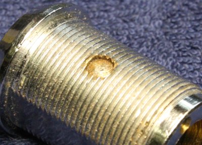
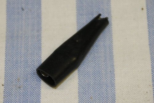
This pin (above.) It's hardened steel. Would involve cutting a groove in the side of the lock with a thin grinding wheel. Don't want to do that.
Oh well, so that was a fruitless trip.
Sigh... well I like a challenge.
Let's try making the tool and picking it myself.
 Pins 1,2,3 and 5,6,7 are normal. Two segments, top segments have various lengths, and there's a spring underneath. With a correct key they all get pressed down so the segment breaks line up with the rotational plane, and the lock can turn.
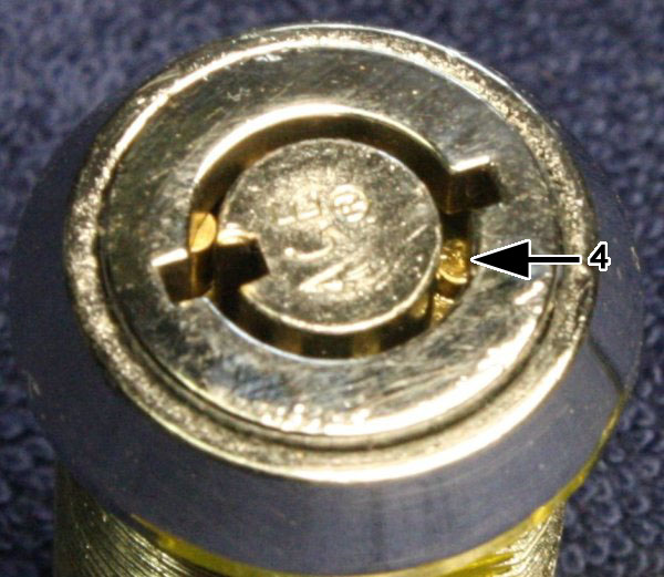
Pin 4 is the unusual one. There's no lower segment, no spring. It's loose to slide up and down in its hole. Also it doesn't push down flush with the cylinder hole bottom, so a key without a recess for it can't be pushed in all the way. But if it isn't held down as the lock is turned, sprung pins will pop up into its hole as they line up with it, jamming the lock.
Here's an oblique view of it. It's pushed down as far as it will go.
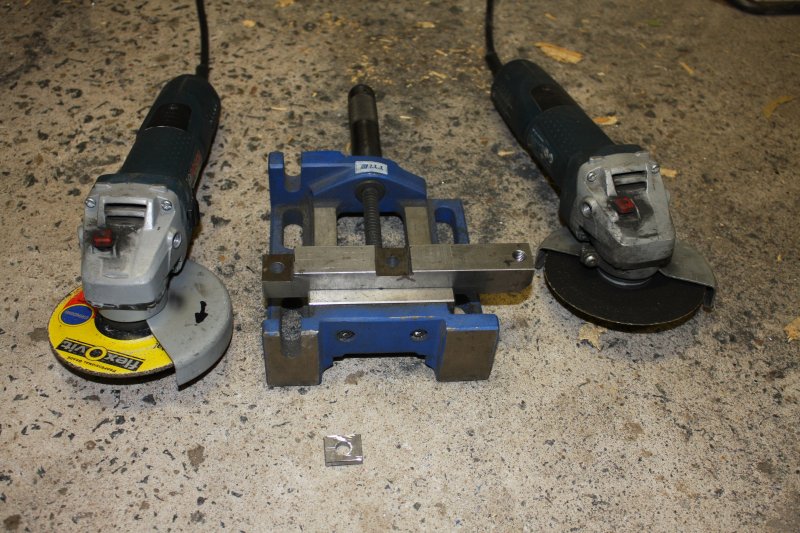
The mounting problem is awkward enough that I never got around to solving it. Now here's an incentive. Good.
 |
 |
 |
 |
 |
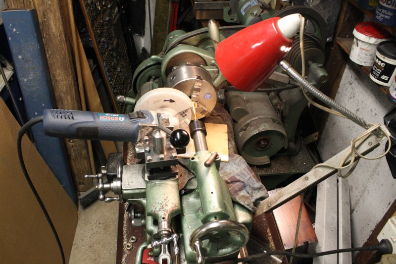
 |
 |
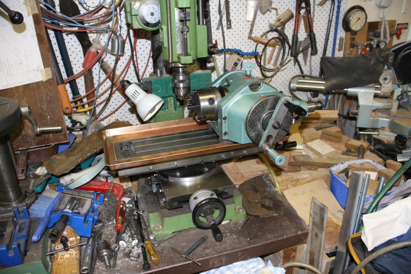
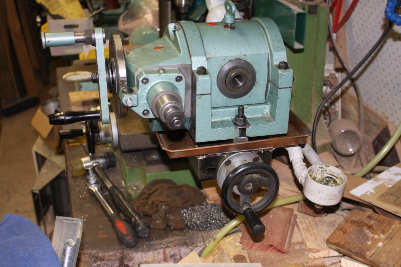
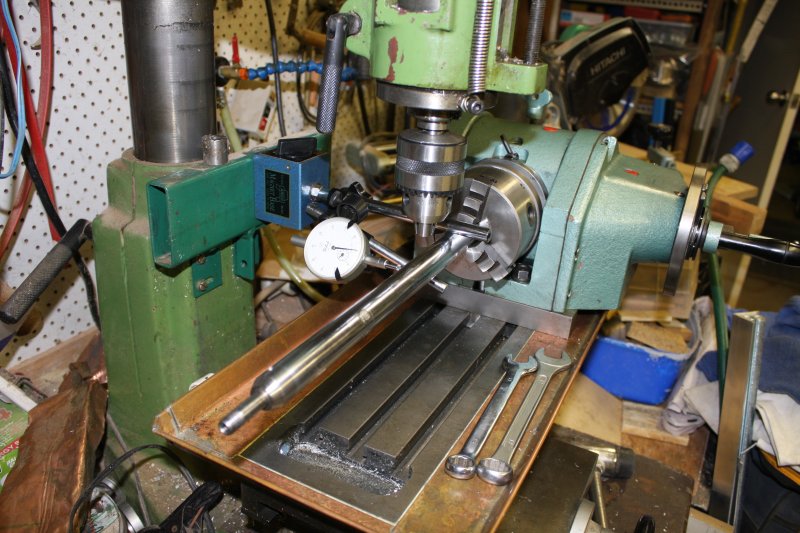
1. About where I want the dividing head. But it has to be spaced up to clear the cutting fluid tray (wish I'd made that wider), and there are no mounting slots over at the far right.
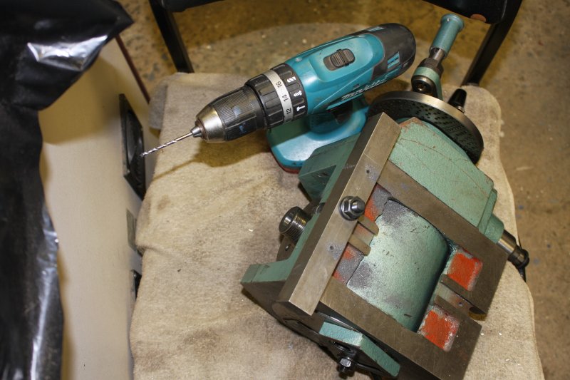
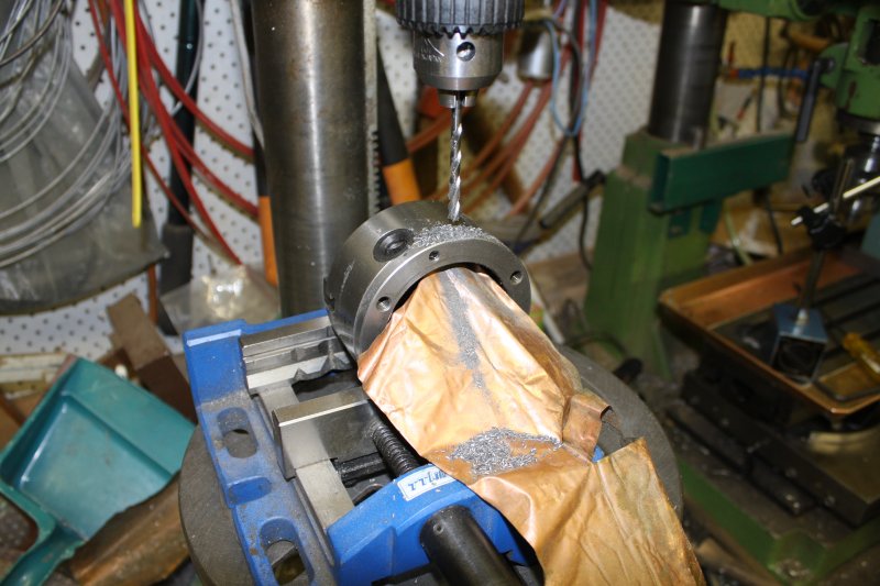
2. The dividing head has to have a pair of new mounting holes. Here drilling pilot holes. Soft cast iron drills easily enough for a hand drill. Fortunately, since there's no way to mount this thing upside down in the drill dress.
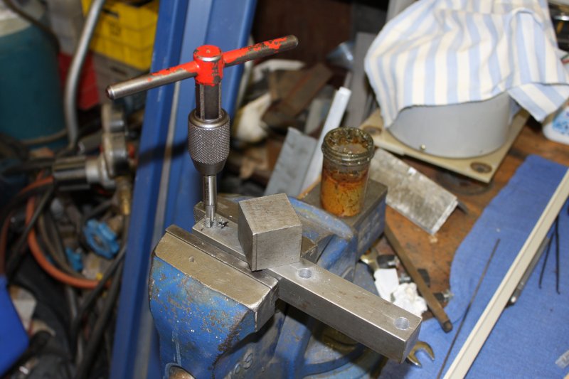
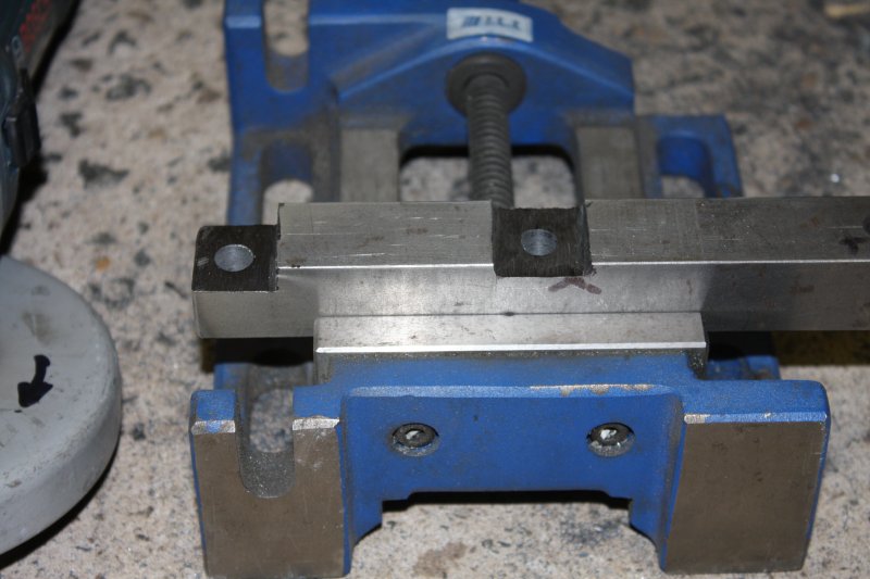
3. This bar provides the far right mounting bolt of the div. head. Which has to be tapped, for an M10 bolt.
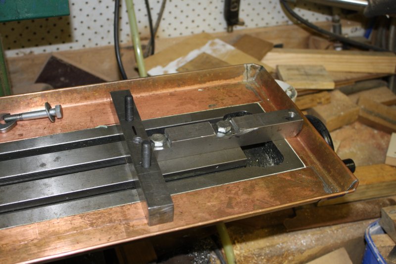
4, 5. Ha ha, the bar needs recesses for the heads of bolts fixing it to the mill T-slots, since the div. head sits on top of it. Ideally I'd have milled these slots... but the mill is being set up for the div. head, and not usable atm. So rough cut the recesses by hand with angle grinders. Precision not required.
 |
 |
 |
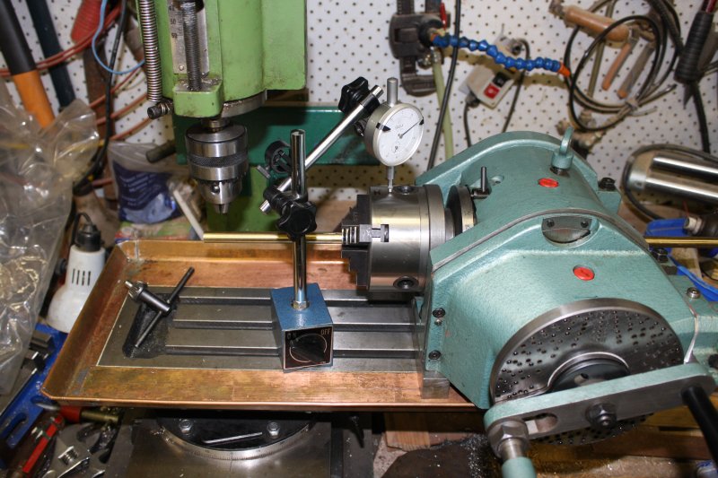 |
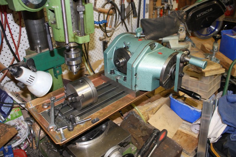
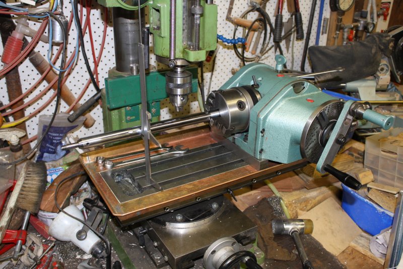
1. The mounting structure, done. 2, 3. Dividing head in place but not aligned yet.
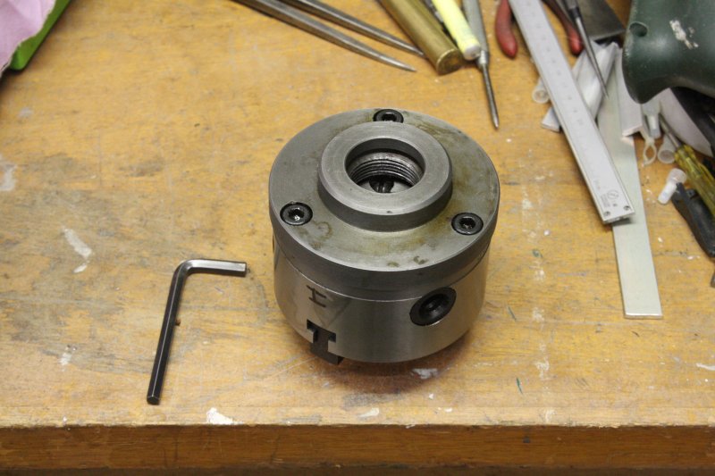
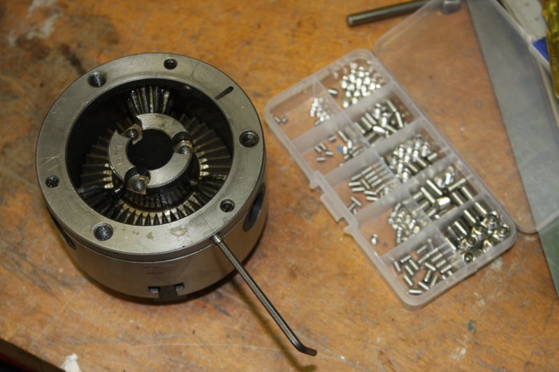
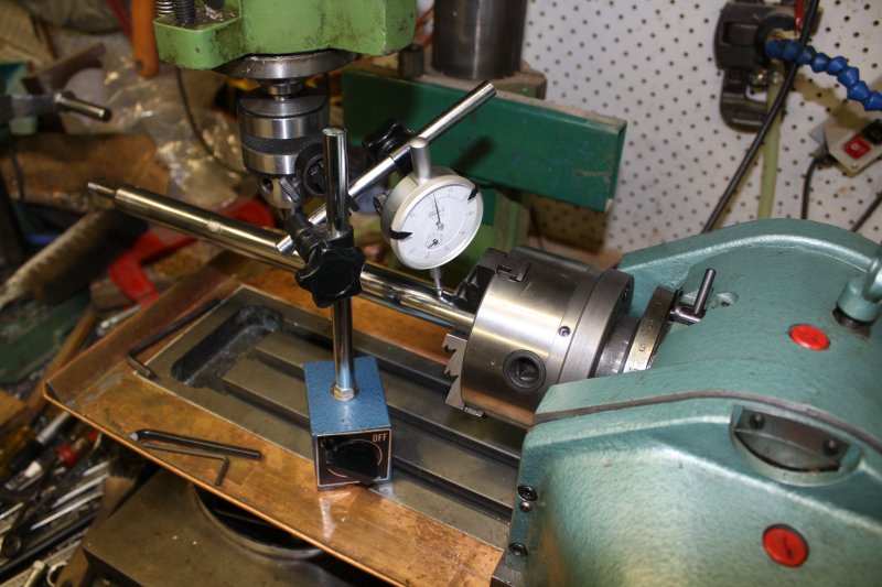
4. Before aligning the chuck axis with the mill Y-travel, I checked the radial run-out of the chuck.
Yuk! It's awful. 0.2mm.
Made in 1988, this machine is a product of the USSR, for export. The Soviet Union dissolved on Dec 26th 1991, and several aspects of this unit (and the rotary table) have a distinct air of 'don't give a shit.' It's easy to see why this ended up in a liquidation sale.
 |
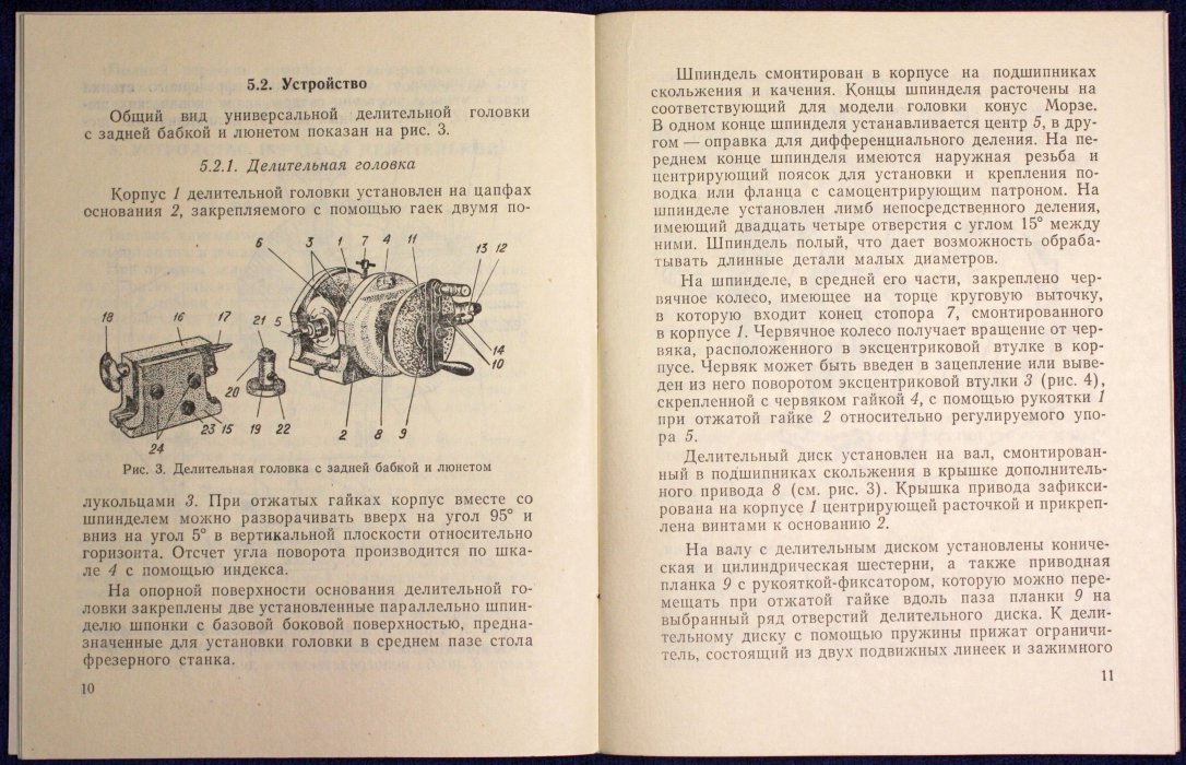 |
But overall it does work, and who needs a manual anyway.
I would like to fix that run-out though. What's the cause?
 |
 |
 |
 |
 |
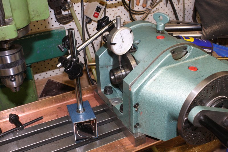
1. It's not the spindle. No detectable run-out here.
2. I'm looking at you, Chuck.
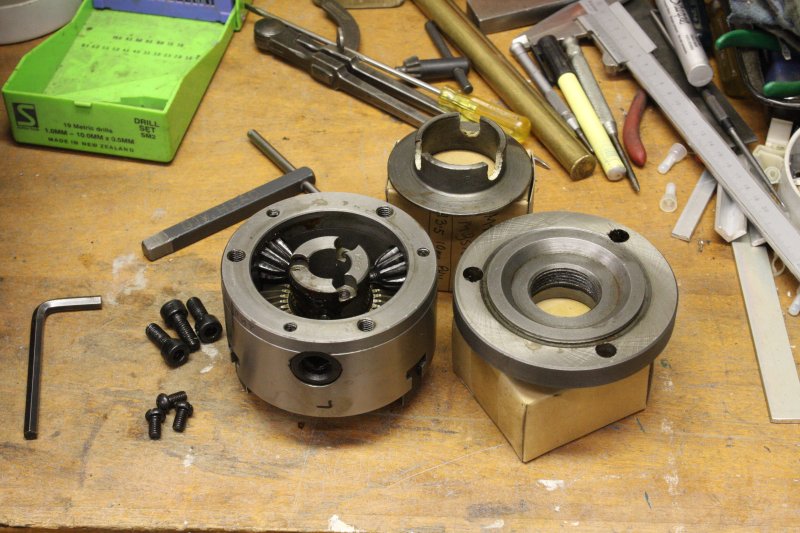
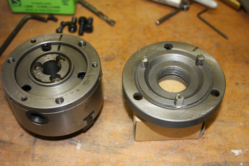
3. Pretty standard construction, except both the adapter plate and the chuck body are CCCP-grade cast iron. This is your industrials on Communism.
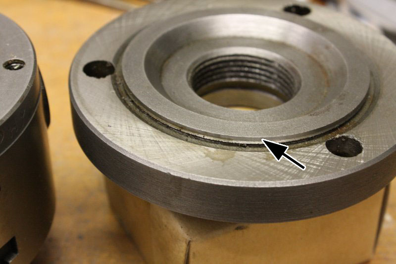
4. There's the culprit. This lip on the adapter plate is supposed to be a press fit into the back of the chuck. Instead it's been cut too deeply, resulting in at least 0.2mm of free radial play. It's virtually impossibly to 'set it right' while tightening the three securing bolts. Another example of 'don't give a shit' slackness.
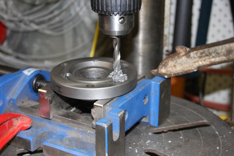
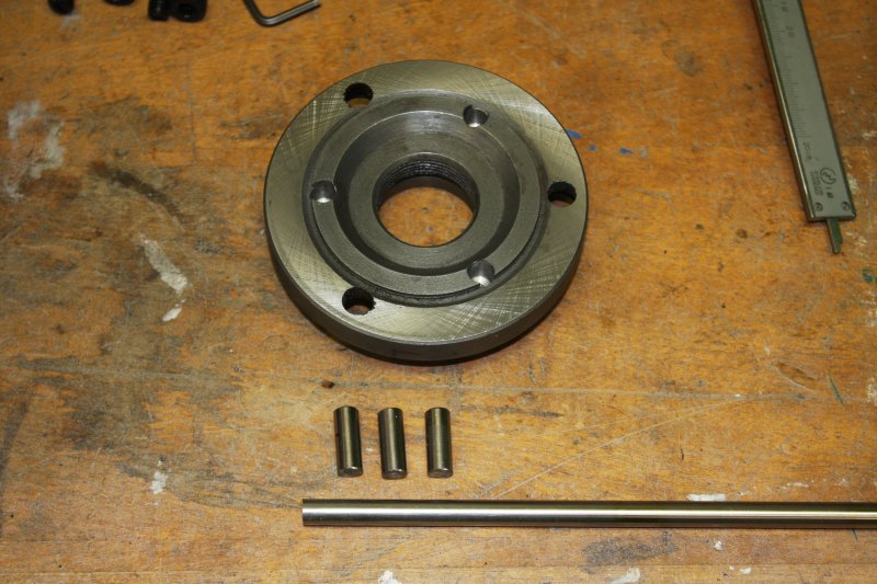
5. Oh well, the solution is not too hard. Add radial centering adjustments. Here starting by drilling holes in the backplate, to fit three pins. It's cast iron, hence the gray dust instead of drill swarf.
 |
 |
 |
 |
 |
1. Actually I wasn't really 'drilling' those holes. Because they needed to be accurate, and also overlapped an edge, and also should be as deep as possible without breaking through the other side, I'd gone full depth with an 8mm (shaft) center drill, then bored out the remainder of the hole to 8mm using a drill bit modified to work as an end mill. Plus I'd deliberately blunted the side flute cutting edges, so the hole would be a little bit under 8mm. And because I'd hand-ground the end face cutting edges (to be nearly flat, like an end mill bit) it really wanted to auger into the soft cast iron. Fortunately I expected that, and didn't try running the drill press under power. Just turned the chuck slowly by hand while giving the cutter a little down-pressure. Also using the drill press end-stop and a clamped-down machine vice.
2. Result: nice clean holes with flat bottoms, that are tight press fits for the 8mm steel rod I picked from the scrap box. The drill isn't broken, that's just the tip I cut off to create a short custom cutter.
3. Hand cutting clearance holes for the pins in this spacer thingy. Its job is putting back-pressure on the chuck spiral gear plate.
4. Drilling holes in the chuck body for the adjuster grub screws. Some copper sheet serves to keep the cast iron dust out of the gears. (Plus blowing with compressed air afterwards.)
5. Putting in the grub screws.
 |
 |
 |
 |
 |
1. Pins cut to length. Due to years of pulling apart junked photocopiers and printers, I have a large box full of precise rods like this, in assorted sizes.
2. Hammered in and ground flat on the faces the grub screws bear on.
3. Annnnd... it worked. With the main bolts a little loose the radial adjustments were easily able to get the chuck centered nicely. Here running a final sanity check with everything tightened up and using a ground rod in the jaws. It ended up with 0.015 mm radial runout, which is good enough for me. Could have got it to zero, but there's a small amount of random error every time the chuck is demounted then mounted again, so little point.
Incidentally that rod is salvaged from a car front shock absorber. Another good source of precision ground rods, just bigger. Angle grinders make such things easily accessible.
4. Making the shaft true to the mill bed horizontal traverse, by moving the whole dividing head on its mounting bolts.
5. Getting it level. The dividing head has an axis of movement for this, but it's stiff and requires gentle persuasion. Hence the rubber mallet.
Hmm... oops, I should have done the leveling adjustment first. Rechecking the traverse... Yep, it's out a bit and needed resetting. Do you see why?
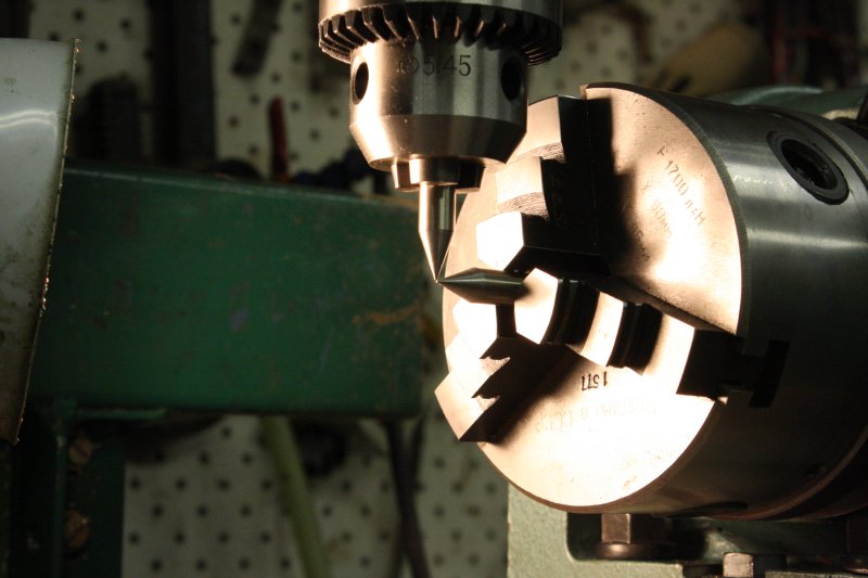
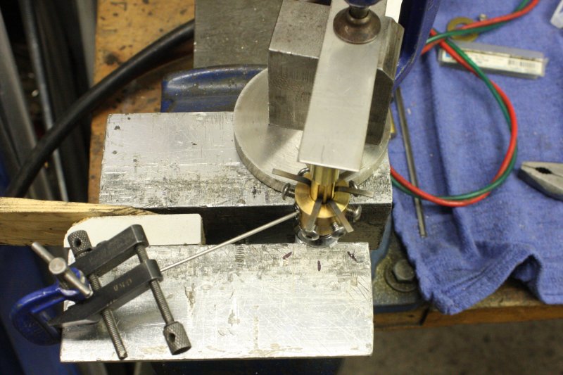
Finally, ready to start on making the lock pick.
 |
 |
 |
 |
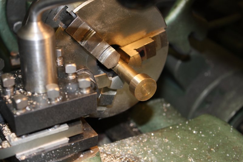
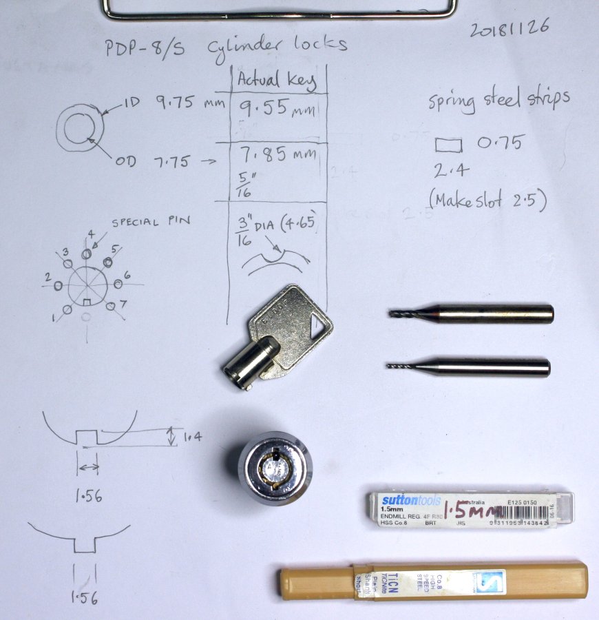
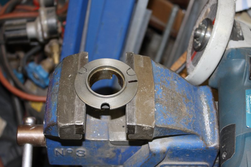
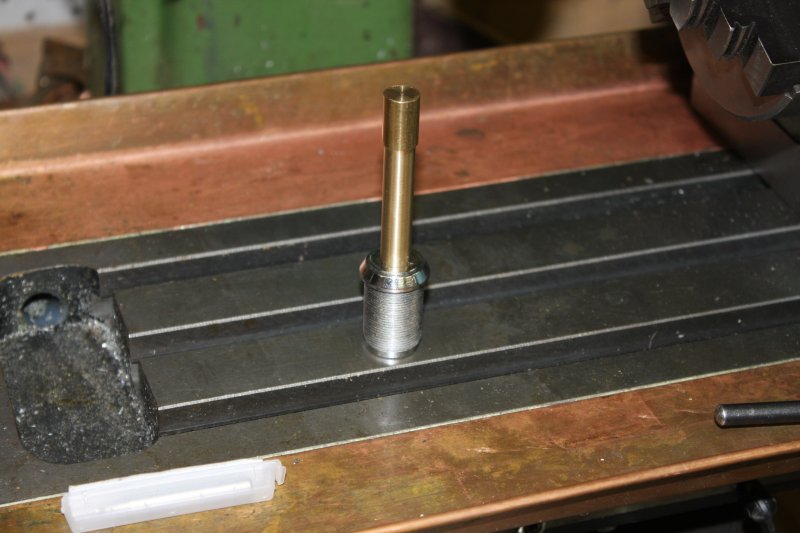
1. Starting with the cylinder.
2. Which fits the lock opening.
3. Setting the mill chuck center in line with the dividing head center.
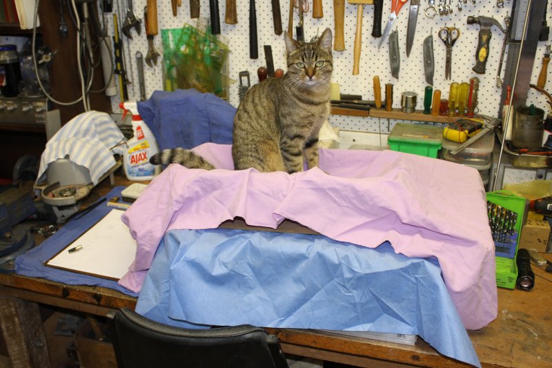
4. Meanwhile the PDP-8 is just sitting under covers on the bench. It and cat are thinking "Geez this is taking sooo long."
 |
 |
 |
 |
 |
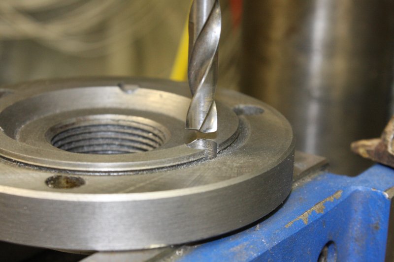
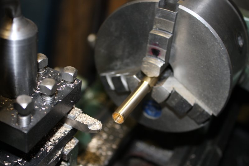
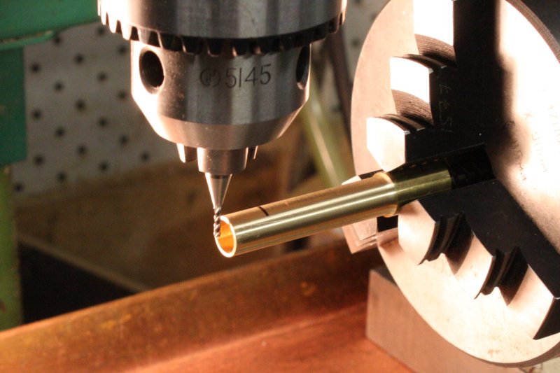
1. About to cut the small 1.5 mm wide slot for the locator tab. I took the cut very slowly, since it would be so easy to break this tiny (but expensive) cutter. With larger cutters there's tactile feedback through the feed screw wheel. You can tell how hard you're pushing it. Not with this one. I expected if I fed the cut too fast I'd just see $35 go 'snap' without any warning.
2. Preparing to cut the pin-presser slide slots with the 2.5 mm diameter mill bit. The most critical dimension is the inner wall thickness, which is 0.2 mm at the thinnest point. Here using a 0.2 mm feeler gauge to set that cutter depth before locking it.
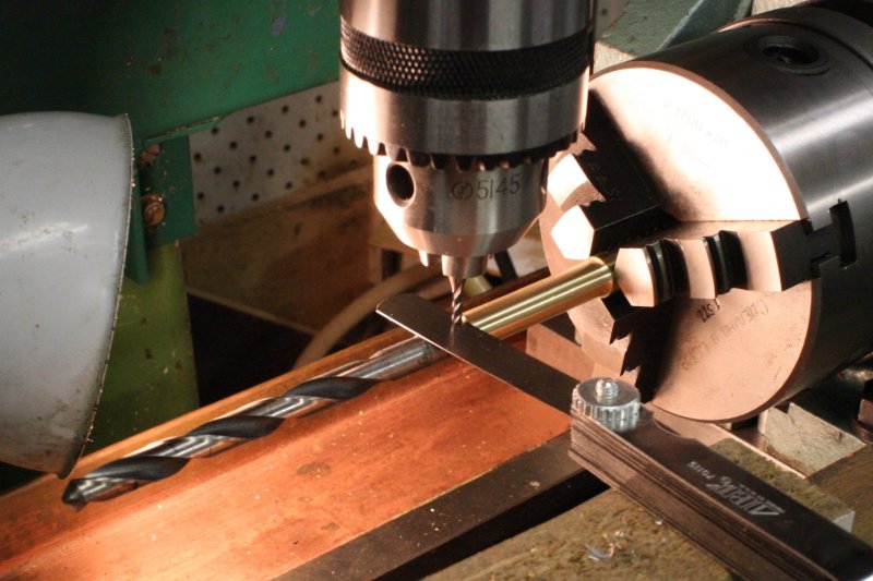
3. Cutting. The pins in cylinder locks are are arranged in 45° steps. This is why the dividing head is needed.
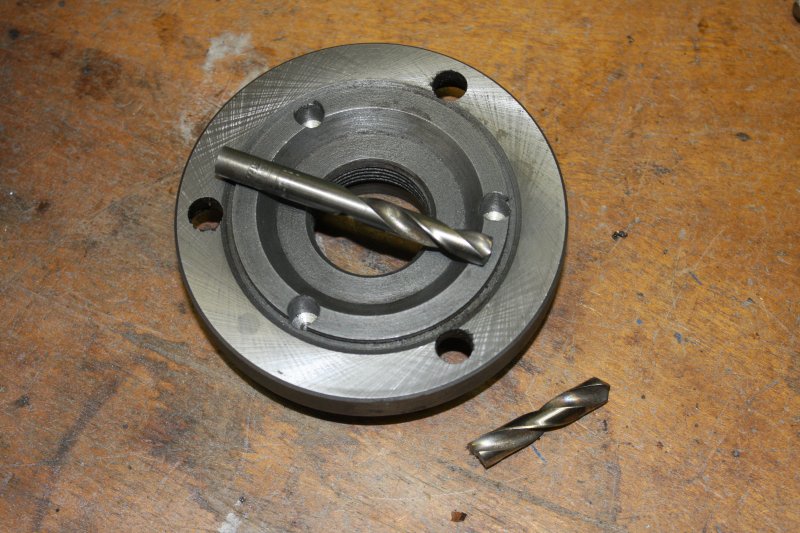
4. It only took a few minutes. All that setting up of the dividing head, and about $70 for the cutters, for this. Ha ha, worth it! Yes it fits nicely. Still more to do though.
5. Needing a tiny little piece of 1.5mm thick brass sheet, it turned out I didn't have any. So an old brass washer will do, after slightly thinning it on the belt sander. Here just working out how best to cut to shape in preparation for silver soldering.
About which... hmmm... the little locating bar will be quite small, with not much area of the join. Ideally I'd use copper-silver alloy solder, but that takes a temperature up near the melting point of brass. On this thin, precise part that will be pretty iffy. Good chance of wrecking it. I also bought some tin-silver solder, but that is much softer. Would it be strong enough? I'm not sure.
 |
 |
 |
 |
 |
 |
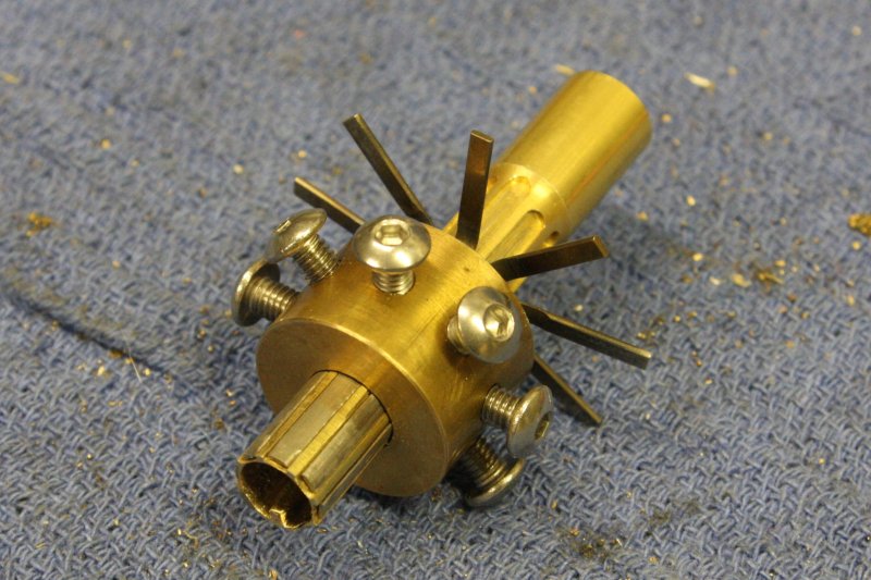
So, procrastinating about which solder to use. Meanwhile there are other parts to machine.
1 - 4. Making the donut for the pin lock screws. Using the dividing head is so much fun! My new favorite tool. Even if this lockpick thing is a complete failure it will have been worth it just because it made me finally set that thing up.
5. The bench about now. Not tooooo bad a mess.
6. Almost finished, right? Just need to cut and bend some spring steel strips (from windscreen wiper blades) for the pin pushers. Well, except that those rectangular strips are a bit too thick, and in this use the outer surface needs to match the round profile of the cylinder lock barrel. This was not a surprise; I'd known it from the start. Just hadn't figured out how I was going to alter the profile of those little steel strips.
 |
 |
 |
 |
 |
 |
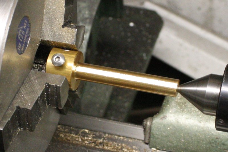
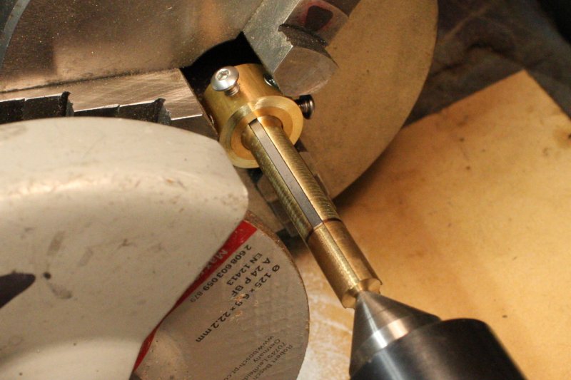
I'd also known it was going to be a pain. The strips have to slide freely in the pick, so have to be pretty smooth. Thinning them down by hand on the belt sander isn't going to work. They have to be close to the radius of the pick cylinder. And sooo...
1. A grinding jig, that is very similar to the pick. Same diameter shaft, but with 3 pin slots instead of 7. The idea is to clamp the steel strips in these slots, then grind them down to match the rod diameter.
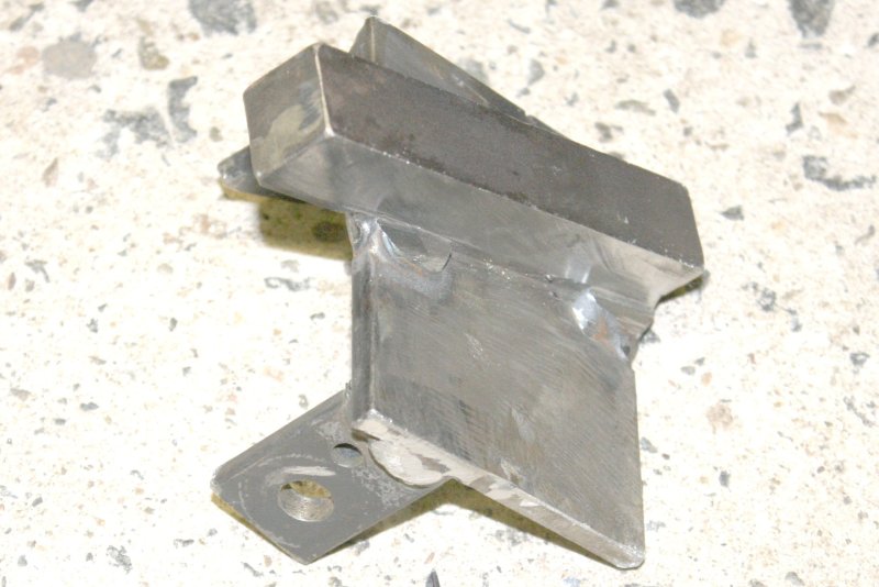
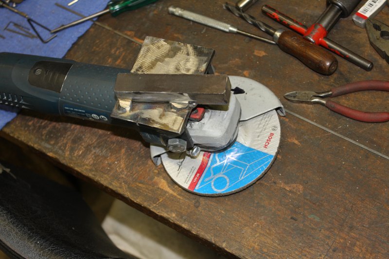
2. After setting that up, is when I discovered that the bracket I'd made a while ago to mount an angle drinder on the lathe toolpost, doesn't fit in this arrangement. Mostly because the lathe tailpost with a live center needs to be used here, so there isn't the needed room. Picture here is a new mounting bracket, quickly made just now.
3 - 5. Setup for grinding the pins.
6. The end result.
When starting this attempt on the PDP-8/s locks, given that the locks appear to be high quality, the cost of the machines back then, and potential security needed, I assumed DEC would have individually keyed the machines.
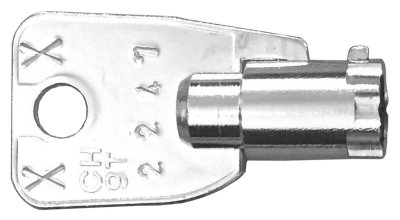
But no! As soon as I mentioned my PDP-8 locks problem on a 'classic computers' mail list, several people commented that in fact, DEC had used a single key for all their machine models over many years. It's called an Ace XX2247, and it's widely available. For instance there's an ebay seller in Melbourne Australia, with them listed for Au$25. It's stated in the advert to fit these DEC computer models:
PDP-8 (Classic), PDP-8/E, PDP-8/I, PDP-8/L (and expansion box), PDP-8/M, PDP-11/20, PDP-11/24, PDP-11/30, PDP-11/44 (BA11-A), PDP-11/45, PDP-11/60, PDP-11/70 and PDP-11/750 (VAX).
OK, so the PDP-8/S is not on that list. Was it just forgotten about, or is it actually different?
Additionally the cut depths of Ace cylinder keys, and the cut numbers for the XX2247 key had been posted on the mail list some years ago. Someone helpfully reposts them:
The standard cut depths: (step is 0.0155")
Huh. Well, I was nearly finished my pick tool, and I do want to have a try at the lock myself. I saved this information in my PDP-8/S project folder, and got on with making the pick. After thinning the steel pins, the last step was fixing the notch keyway. I decided to use the tougher/hotter copper-silver solder, and the pick's fine brass cylinder end survived this operation adequately.
With the pick tool assembled, and in the lock with a fine torsion spring bar, plus pin 4's slider set and locked to fit that semi-pin's height, it fits nicely. I can push all the lock's pins down freely, and apply variable torsion.
But... no quick success. I can feel some varying friction on pins, and various steps in resistance. But nothing consistent. I wonder if this is using mushroom pins? (That have narrower necks machined in the pins, to mess with the way they feel to a pick like this.)
Oh well. However I do have that set of cut numbers. So which way does that 5-1-7-3-7-5-7 sequence go around the lock? The listing post seemed to say, the same way as I'd numbered them here.
 But are they? If I set the lockpick to those and it doesn't work, I won't know if that's because the PDP-8/S is omitted from that list because it really is different, or what.
Fortunately there's a picture of the XX2247 key online. And it shows cut numbers 1 & 3 (by my numbering) quite deep and the same. So if that sequence from the mail list is correct, the three visible notches are the "7 5 7" and the list is backwards.
Using a vernier caliper I set the pins in my pick to these depths:
 |
Ah! But with the lock rotated half a pin separation, I can use the lock to reset the lockpick pin depths exactly.
That worked. With the lockpick reset in the lock, it now turns nice and smoothly. Video at left.
Then off to the locksmiths again, to get a propper key made. The key copied from my pick is not quite so smooth-turning. Seems like the copying machine introduces some small errors in the cut depth. But the key does the job.
The other not so quick. Another unexpected surge of vintage computing gear. Meaning more things on my plate that had to be dealt with immediately.
 |
 |
 |
 |
 |
 |
 |
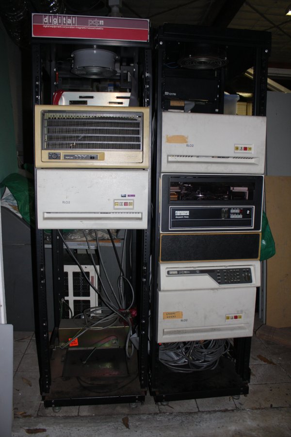
1. Two racks of DEC gear. On the left a PDP-11/44, on the right a PDP-11/34 system that seems to be fairly complete. No urgent chores with these, but they sure are heavy. The usual ropes and winching rigmarole to get them off the trailer.
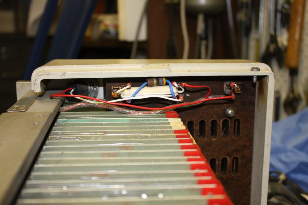
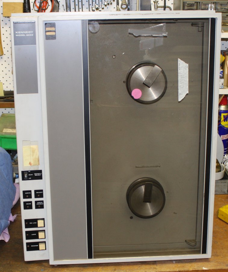
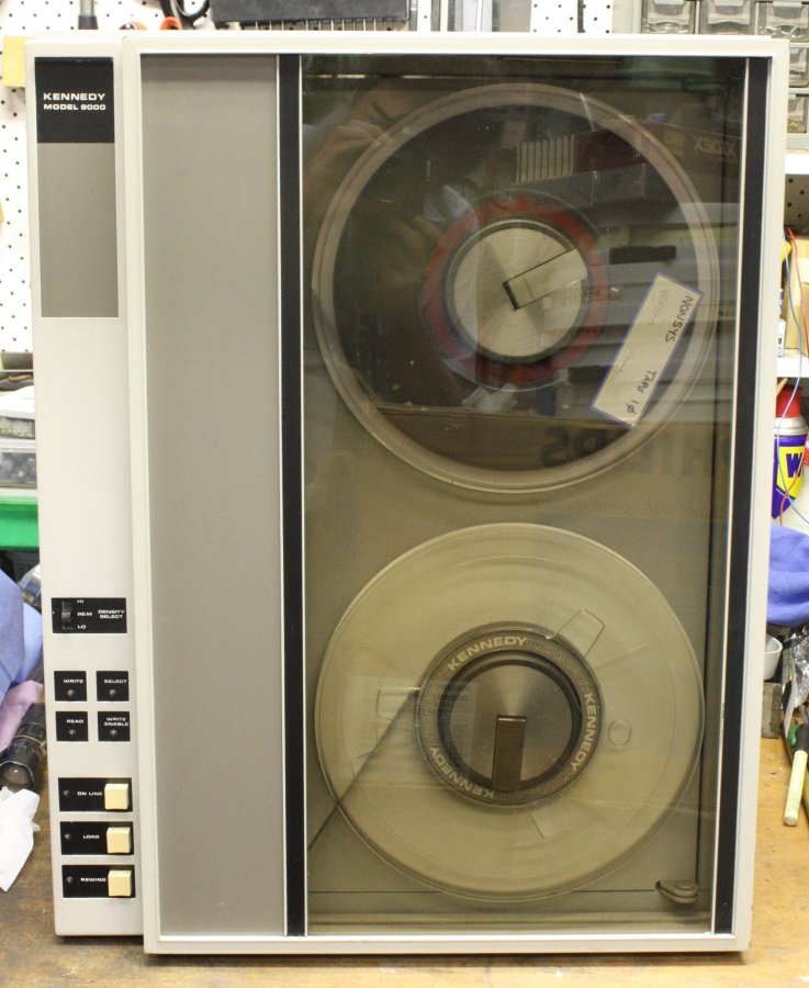
2. A Kennedy model 9000 tape drive. Dirty but otherwise seems in good condition. Of course no cables or interface. But I don't want to put this in storage without a cleaning at least.
3. Post-cleaning. My god, getting old, hardenned 'magic invisible tape' off perspex without scuffing the surface is a pain. The drive still needs other repairs. For one thing a new capstan rubber, and the top panel is rusty. But those can wait. Pitty about the capstan, as the cracked rubber could damage a tape so I'd better not try just turning it on and attempting to spin some tape reels. Patience...
4. Internals are fairly clean. One small problem — both door detent thingies were chrome plated. The outer door one is fine, but the inner one's chrome is flaking off badly. Resulting in little metalic fragments that could fall into the electronics. Not good. I decided to fix that now.
5. The arm with most chrome removed. (I forgot to take a picture of the flaking very poor plating.) But I can't get at the plating where the rivets are. So drilled them out too.
6. Painted, rivetted. Re-chroming it would have caused too much delay, and I need to get this off the bench asap.
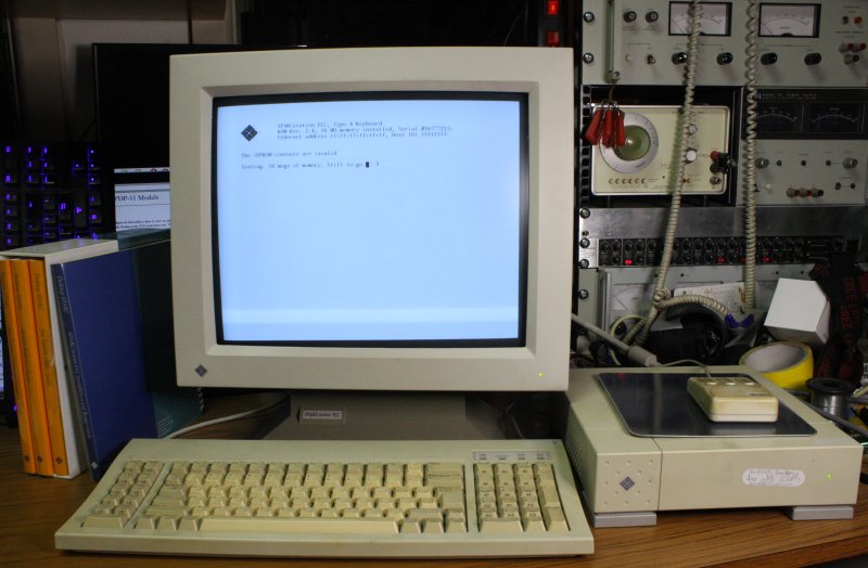
7. There were a few other items in this surge, but perhaps the nicest of all is a SUN SPARCstation ELC. Introduced around 1991. It runs, but of course has lost its NVRAM contents so can't boot. Also the monitor developed a flickering problem. Both those can wait. thankfully there is no NiCad battery; those allways leaked and destroyed whatever circuit board they were on. The thing that immediately stands out with this system, is the bootrom has a lovely text font built in. Meanwhile nearly 30 years later the PC family still has braindead BIOS fonts.
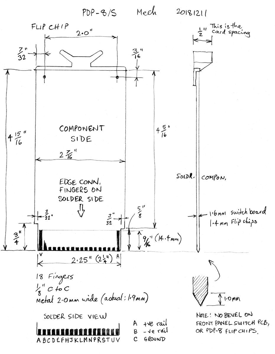
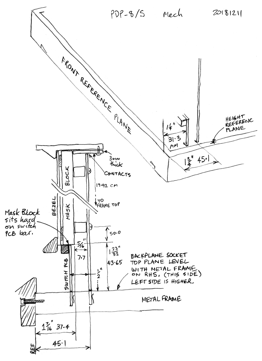
For the dimensions the only safe way to get those is to measure them myself, from the actual machine. 'Safe' as in, I'm going to be putting some work into a PCB layout, then paying to have it made. Would be nice if it was right first time.
 |
 |
 |
 |
 |
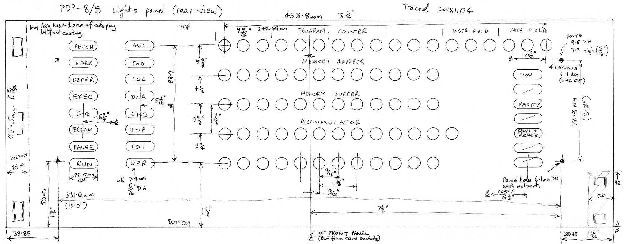
1. Starting. The lights PCB plugs into a whole row of backplane connectors, same as the switches PCB does. It also spans from the backplane, to the mounting posts on the machine's front bezel structure. Lots of dimensions to get exactly right, or else.
This involved some close examination of the machine, plus assembling and removing the front panel a few times. Resulting in discovering a few more details and little problems with the machine.
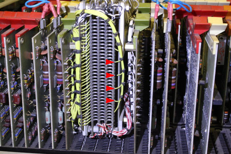
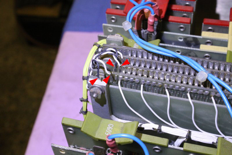
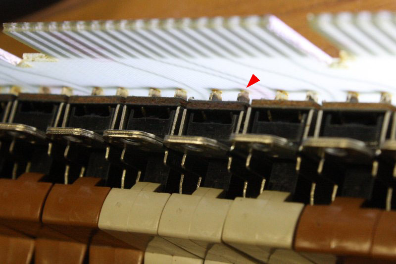
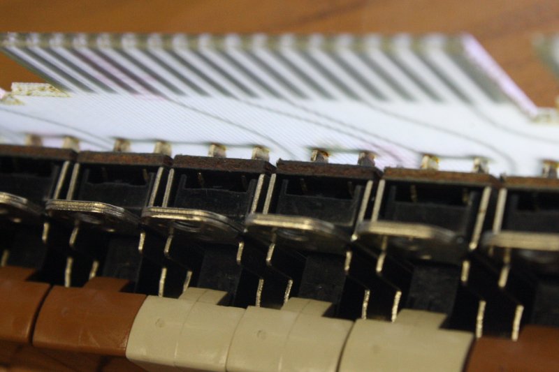
2, 3. While admiring the core memory block I discovered three tiny wires broken off. And some others that have very weak-feeling joins, obviously near fatigue failure. Looks like these broke off due to the cabling being pushed back and forth. (Not by me!) Arrows show the broken and weak joints.
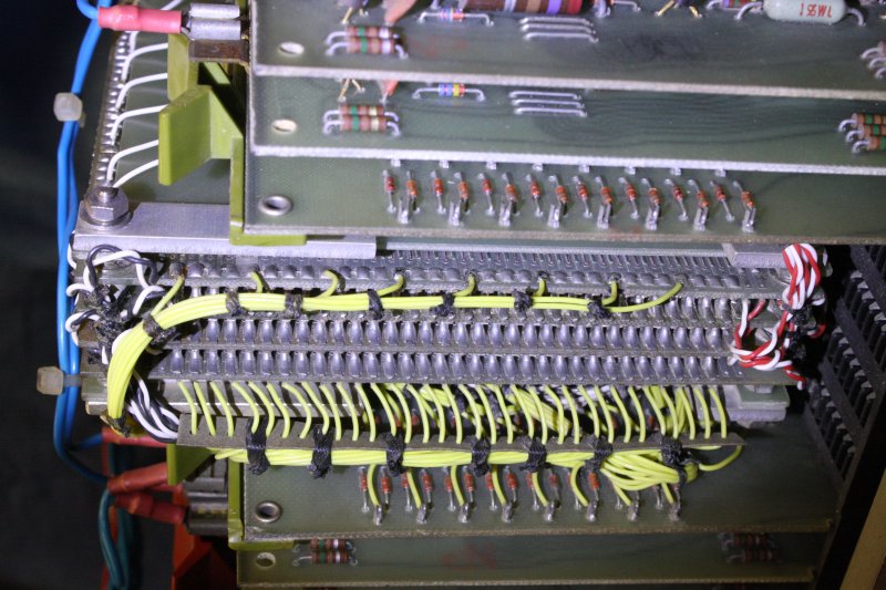
4, 5. Fixed.
 |
 |
 |
 |
 |
1. That wasn't exactly microsurgery, but needed a lot of care because I daren't take the whole memory module out (yet) and so four of the repairs had to be done directly above the open structure of the core memory planes. this needed extreme soldering care to not drop anything in there.
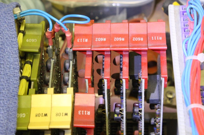
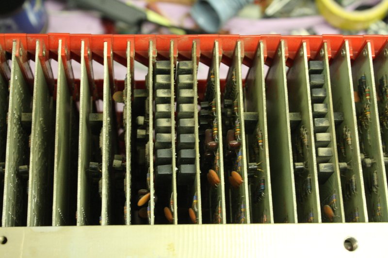
2. This is a bit scary too. I have not removed more than one flip chip at a time so far, because I don't yet have a verified chart of where they all go. Cleaning them and the backplane connectors has to wait for that. But now I notice this. See the three R602 cards there? They should be the same circuitry, but they are not. Same PCB, but the circuitry has some different component loads. Hmm... Potential trap for the unwary. More to research.
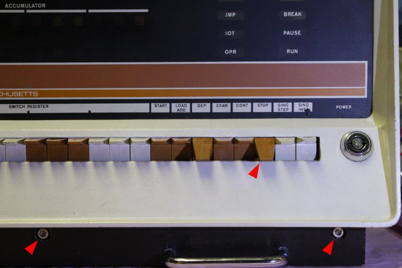
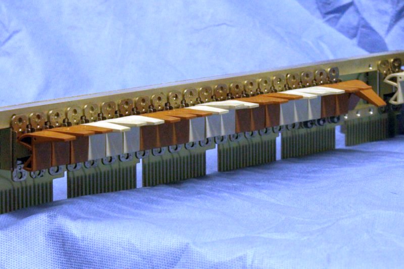
3. Then there's annoying problems, like this. The DEP switch has spring return to down, but the EXAM, CONT and STOP switches have spring returns to up. Yet the STOP switch now sticks in the down position. The other two are a bit reluctant to spring up properly too. When I first examined the machine all the springs were tired, and I fixed that by stretching them. They're still fine if the front metalwork is removed.
What's happening is that the switch paddle is rubbing on the metalwork, with enough friction to make it stick. Why?
Ha ha, this led into a whole saga of discovery about DEC's production tolerances and quality control.
Those three stainless machine head screws that hold on the front casting, are UNC #10, 4.7 mm diameter. Their holes in the casting are 6.0 mm dia. So there's around 1.3 mm of potential 'wiggle' in the casting before tightening the screws. Seems a surprising amount.
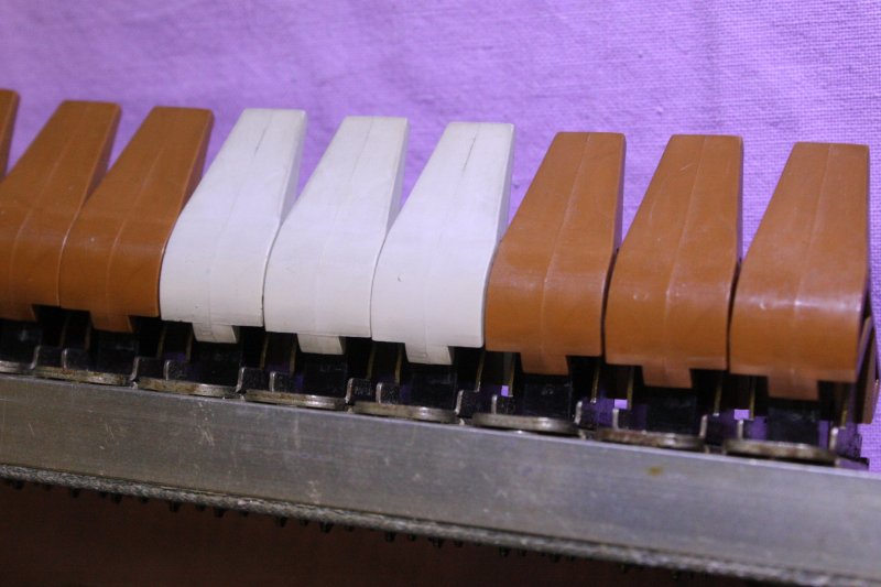
4. Here's DEC's reason. When free, those paddle switches are pretty sloppy in their position of end of travel. In this photo I've pressed them all up to their stop positions. Ragged, and the row doesn't look neat.
So DEC designed the front casting to provide a straight 'end stop' for the up positions. But there's a problem...
5. The paddles have a radius centered on their pivot. So as they are pressed down, the body is still potentially rubbing on the front cast metal 'stop' edge. Also the plastic body of the paddle has a molding ridge down the middle, and this continues around the radius.
Result: to get this exactly right, the front casting should be adjusted in position so it does its 'end stop' duty, but is juuust high enough to not rub on the switch paddles as they rotate down.
Hence the designed 1.3mm wiggle on the mounting screws. Apparently when reattaching the front casting you are supposed to adjust its position till the switches rest against the metal and sit straight when up, but don't bind when moving.
Urgh. Workable I guess. Except, when I made the metal frame of the bottom cover, I machined it to take out that 1.3 mm play. With it attached the front casting is 'down' on the loose screw holes.
Sigh. OK. I milled 0.5 mm off the three contact points of the front bar in my base cover. This was quite a pain, with disassembly and reassembly, and also the mill having the dividing head mounted so there's little room on the bed. Was it enough?
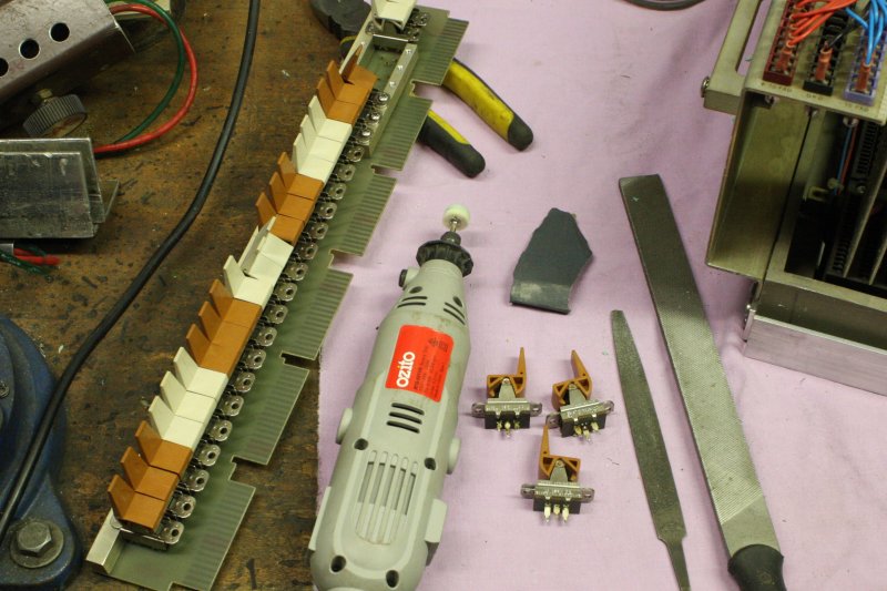
Nope. Better, very close, but that paddle still tends to bind a bit, sometimes. Dammit. Taking off another 0.5 mm would definitely fix this, but it's so much rigmarole, plus then I'd have to mill the entire length of the castellations, to avoid surfaces rubbing on those delicate decals. It would be so much easier to just shave off a teeny bit of plastic from the paddle rear curves. Which are not visible in use. Ok...
 |
 |
 |
 |
 |
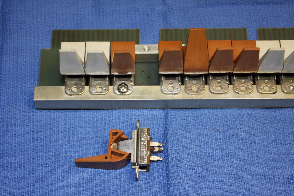
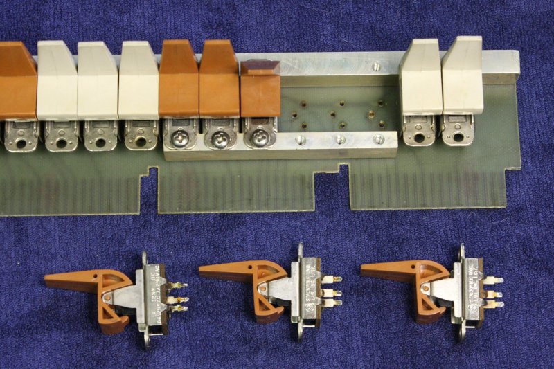
1. Switches removed. It's easy. But do you notice the odd one out? I didn't at this point.
2. A touch with a file, and a bit of polish.
3. Result.
4, 5. I was glad I did that, because while doing so I found not one but two other problems with this switch bar. Here's one. During manufacture one of the switches wasn't pushed down fully before soldering. It's the one that has the very noticeable higher paddle in the 'all up' photo above. An easy fix. Desolder, push down, resolder.
 |
 |
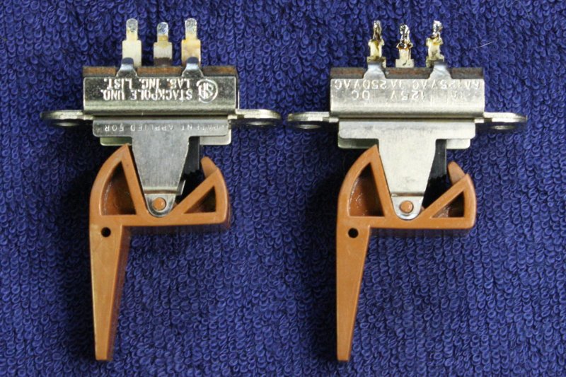
Here's the other, and this one is pretty weird. Of those three paddles removed for 'shaving', one is different. It's accidentally different, an original manufacturing goof. It has wrong shaped pins.
(The one on the right in both pics)
The height from the switch body to the pin shoulder is slightly higher than the correct ones, so the insulating sheet was under pressure. Which over time bowed it inwards. (See pic 2.) This was making the slide inside tend to jam — yet another reason one of the paddles was 'sticky'.
Solution: Loosen the tabs slightly, and cut back the pin shoulders a little. Now when it's screwed down and soldered it works freely like the other switches.
 |
 |
|
I guess I should also do some flip-chip extender cards and prototyping boards.
It's really quaint how they used inch and fractions for everything. Only a few dimensions didn't seem to be some obvious Imperial fraction, so I only noted it in millimeters.
Then on Saturday 20190511, I was helping with an ACMS working bee day. Which began with picking up and moving to storage some equipment from an elder of the Australian computing scene. In chat while shifting stuff, I'd mentioned I was restoring a PDP-8/S, but it was missing some parts. The 'elder' asked if I'd like another one. I asked him what he meant. In an adjacent room he pointed to a PDP-8/S sitting on the floor. "That one. Do you want it?"
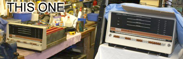 In any condition, I'd have accepted gladly. (Flip Chip spares!) But quick inspection showed it's more complete than mine. Best of all it has the front panel lights board! That solves the problem of lacking a schematic. The PCB is simple. Plus this unit has all the mounting hardware for that assembly, some of which I didn't know was supposed to exist.
Thanks Max! Also for the PDP-8/S related books.
So now I have two machines. One (I've worked on so far) belongs to ACMS — which is only relevant if they ever ask for it back.
 But this one is mine! Wheee! I think it's quite amusing that my first DEC minicomputer has the distinction of being the slowest computer DEC ever produced, and then so is my second one.
Too bad I still don't have a power supply. I'm told the transformer and other supply parts were mounted on the cabinet rear panel. How come people can so rarely keep these bits together with old gear?
It's going to have to be box-stored for a while though. Present time demands and a health problem don't allow for adding this to the workshop 'standing queue.'
 |
 |
 |
 |
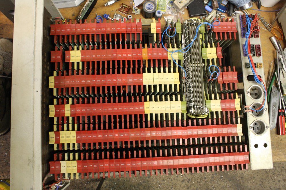
1,2. Flip Chips set. There are a few differences to the other unit. This one has more, suggesting my first one has 2 or 3 cards missing and maybe some in the wrong slots.
3. This one came with a key! Albeit a bit rusty and dusty. Yes, it fits the other machine too.
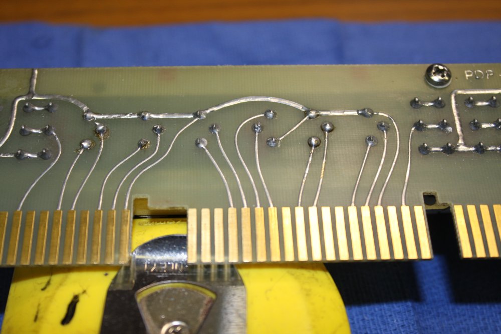
4. The backplane wiring. Whether the mods are the same, remains to be seen. This is a later model; SN 759 vs 700. How often did they change?
 |
 |
 |
 |
1. Some airflow dust deposits on this one.
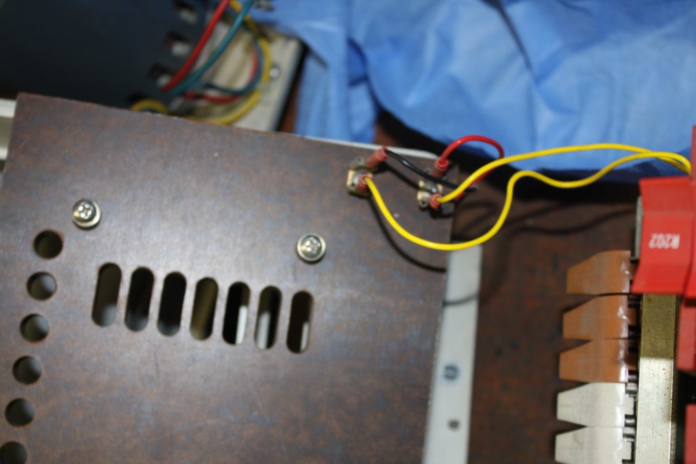
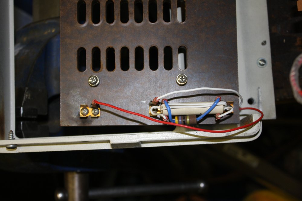
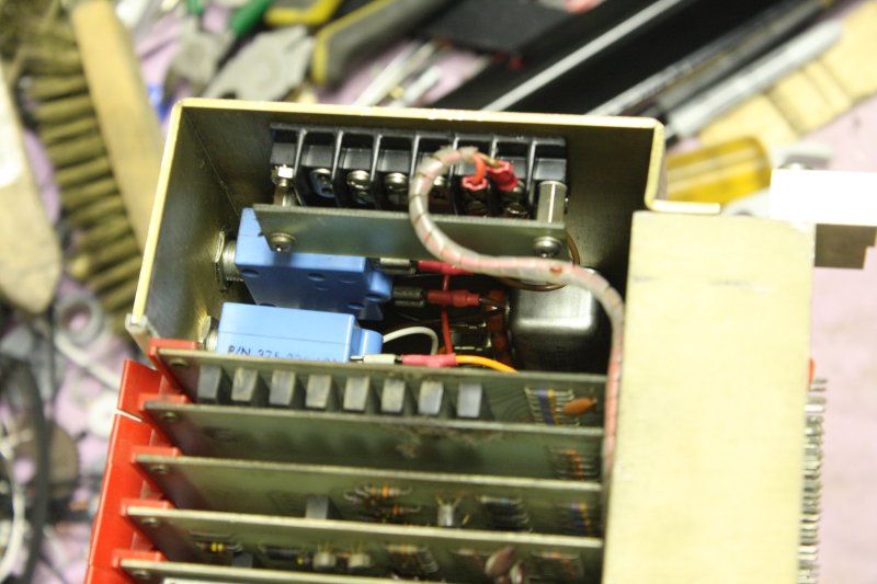
2. Original mains power circuits intact here.
3. Well well. See the quite large gap between the switches and the fascia casting above them? Several mm different to the most that was possible on the other machine. Either the casting opening or the location of the switch board has changed. Did DEC fix that tollerance issue the earlier machines had? Some of the sprung (momentary) switches do have the same 'tired springs' though.
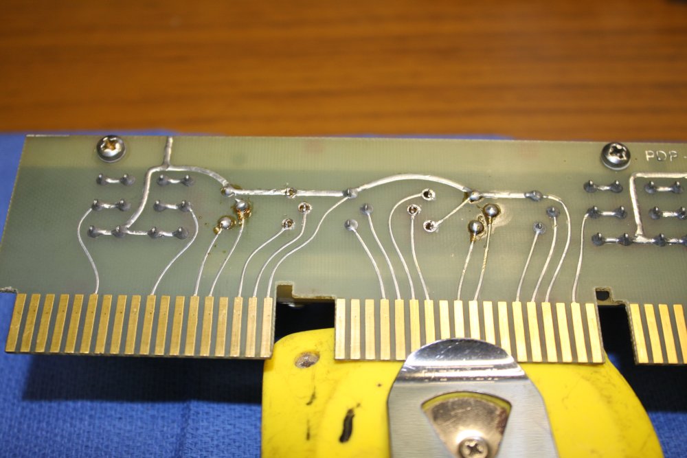
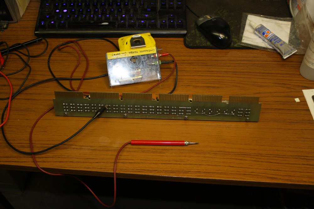
4. So that's what the front panel lights PCB looks like. It's very low tech. The tracks artwork was done quite roughly by hand with tapes. Anyway, now it will be easy to replicate for the other machine.
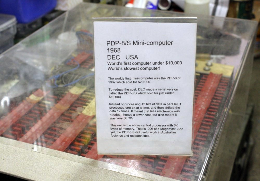
This machine had been an exhibit, and came with a folded perspex cover and display description. Nice.