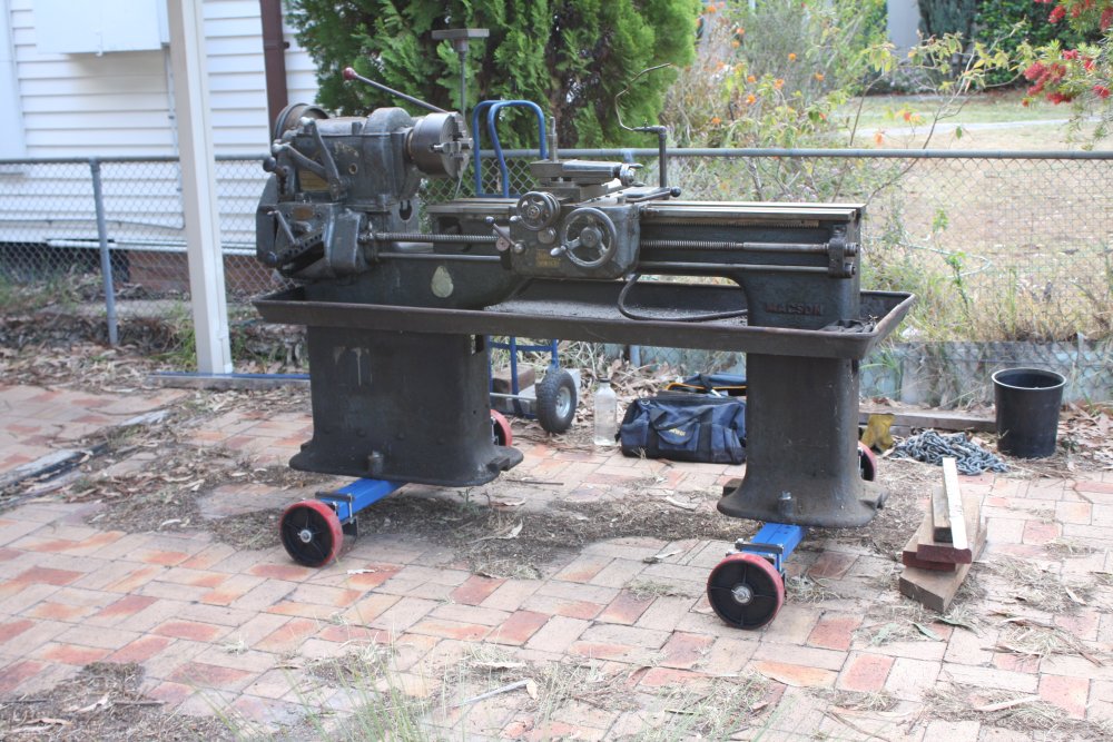
Now I know I will be fetching my UPS from the factory in Albury, there remains the issue of how to actually move it. According to the manual the UPS electronics cabinet weighs 210 Kg. Dimensions are 520 x 788 x 1530mm.
Nowhere near as difficult as the big old Macson lathe I moved recently, but then I'll be doing the UPS entirely by myself. No Hiab crane truck. I have to arrive in Albury with everything needed to get it out of the building and onto my trailer.
Which means a plan is essential.
Also according to the manual, the cabinet has wheels of some sort built into the base of the cabinet, as well as screw-down feet. But I think I'd better not rely on those wheels. They may be removed, broken, or just not adequate for any step obstacles on the route out of the building. So I need a moving dolly and other mechanisms for the stages:
- Getting it up off the floor, onto the dolly. (Lacking a hoist: Wedges & levers, chocks, ramp; that sort of rigmarole.)
- Rolling it out on the dolly, including dealing with any potential slope and discontinuities in the floor and outside path.
- Getting it off the dolly and onto the trailer. (Ummm...? A ramp and rope winching?)
- And of course the reverse of those steps, once I get it back to my workshop.
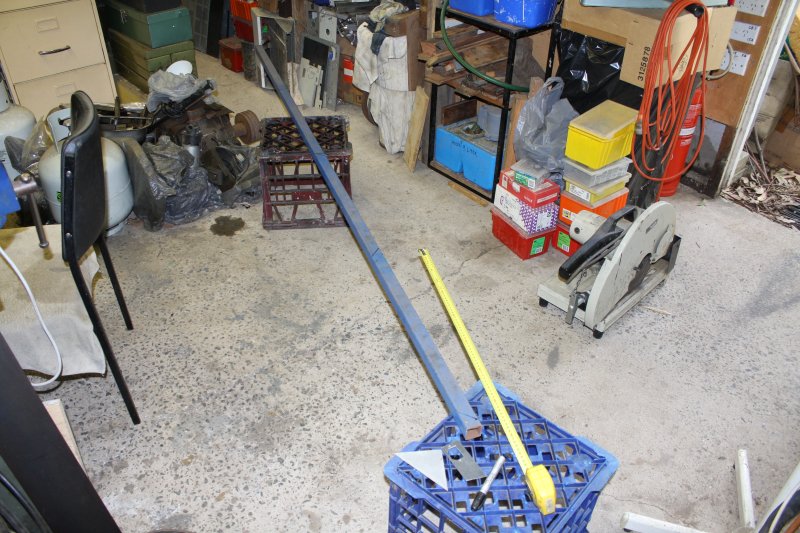
First idea was to re-use the wheel base I'd made for the lathe. Problems:
- Those beams are too long to pass through doorways. I'd have to cut them down (not so safe for the lathe), or buy more steel.
- I don't know of any mounting holes in the UPS base to bolt them too.
- For this I need to be able to steer it. No 'slightly curved path' like with the lathe.
- I'm already using those wheels on the movable frame for my spare Subaru engine. They can be removed, but...
It's too heavy for a simple mover's hand trolley. So, something like a 4-wheeled moving dolly. Only larger. Bunnings have dollies, but they are all too small and have inadequate carry capacity. Besides, I want some aid to getting heavy things up onto it, like a side or end ramp. I'll have to make one.
Sigh. Here we go again. Mechanical construction, in the pursuit of electronics. How exciting, not.
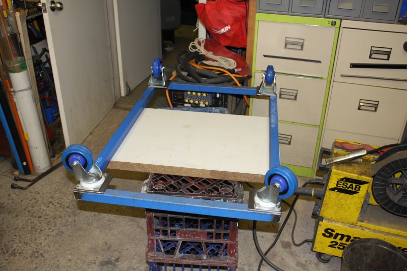
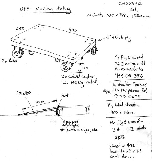 Examining the simplest possible form first: just a sheet of thick plywood (say 1" / 25mm) with castor wheels bolted on the corners.
I bought four castors, rated 140 Kg each. That should do.
But the ply... couldn't find a nearby timber yard with such thick sheets. One in Alexandria (40 minutes drive via an expressway) has it, but it's $158 for a 2.4 x 1.2m sheet.
$78 for a half sheet, but that's not big enough for the dolly and side ramp. If I buy a full sheet, there'd be slow drive back with it on roofracks, plus a bulky offcut to store afterwards. Annnnd... I'm not even sure 1" ply is adequately strong for the span of the dolly.
Then there'd be mount points for a side ramp. Wide sides, or narrow ends?
Both would be nice. Do those just mount on the plywood? Hmm...
Instead of spending money, I'd much prefer to use whatever I have lying around. Free, plus it uses up bulky leftovers, converting storage problems into something useful.
 |
 |
 |
 |
 |
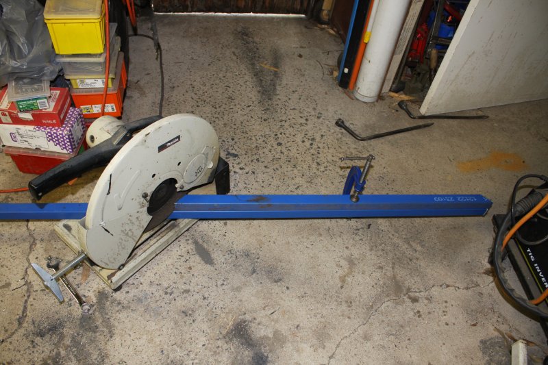
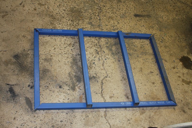
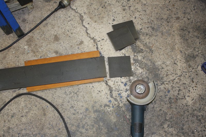
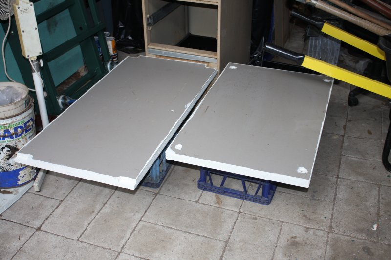
1. What I have, is several lengths of this 35 x 35mm steel section, and some large 35mm thick chipboard panels.
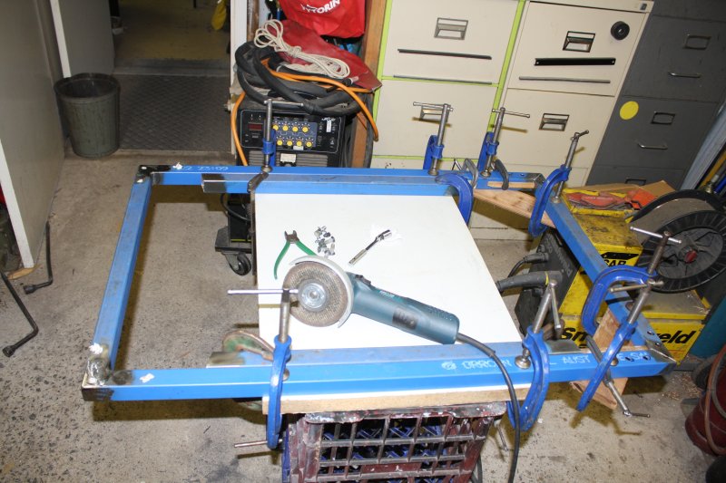
2. And so, after only a sketchy plan, the first cuts.
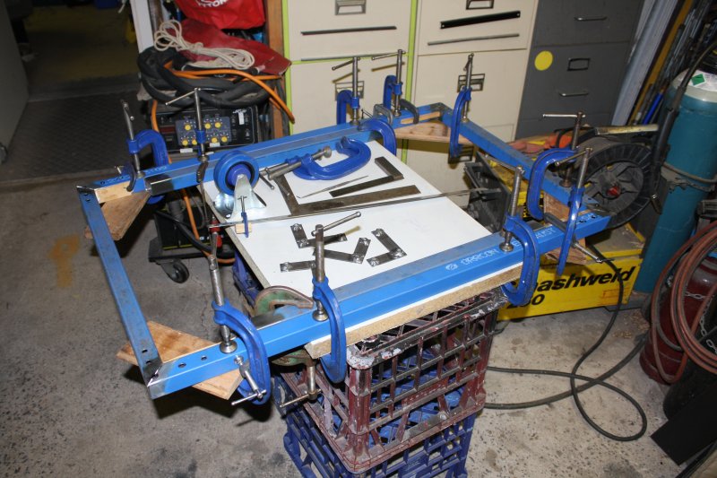
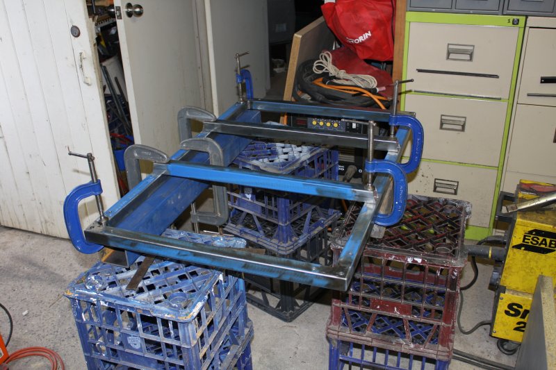
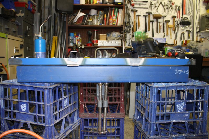
3. Dolly looks roughly like this. Told you not to expect much kawaii.
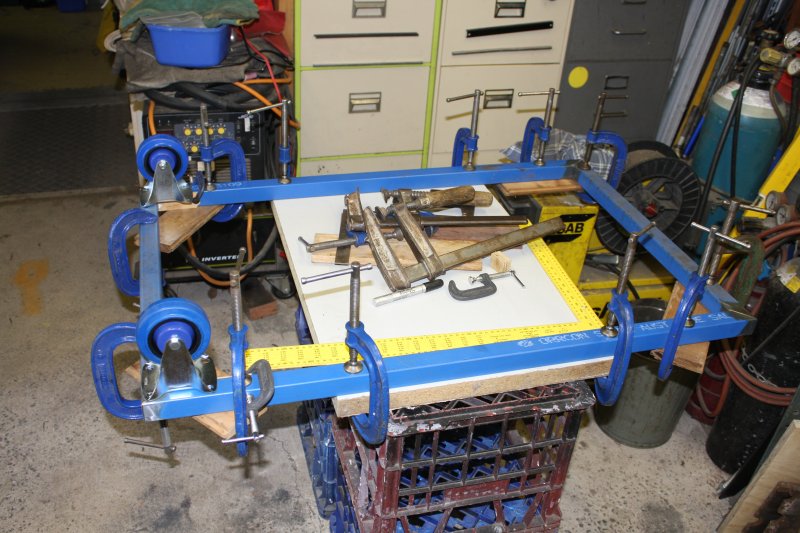
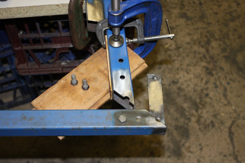
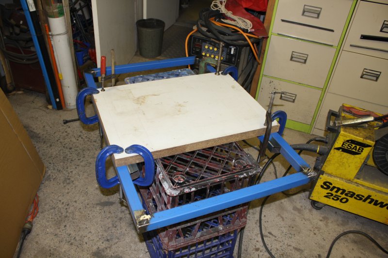
4. Clamped up in position accurately. The thick board isn't part of the dolly, it's just something rigid to clamp to.
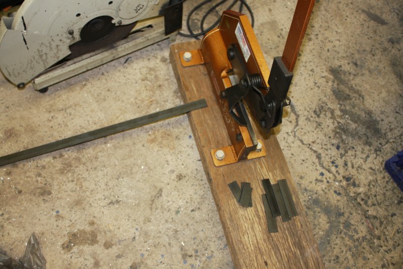
5. The usual story — bolts need nuts inside the frame, so here cutting some strips to weld the nuts to.
 |
 |
 |
 |
 |
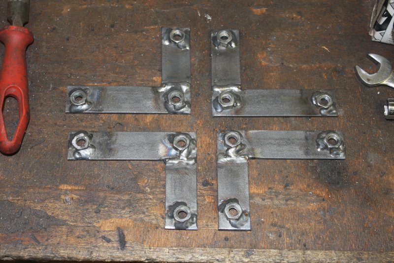
1, 2. Welding the strips into L shapes, to sit in the frame corners.
3, 4. Welding the nuts onto the strips. Hmm... I forgot to take pics of a wooden drill template I'd made. Just a bit of 3mm MDF, with small pilot holes to match the castor wheel mount plates. Used the template to drill all holes in these strips and the frame corners, so they all line up.
5. Holes drilled in the frame, for the bolts and spot welds.
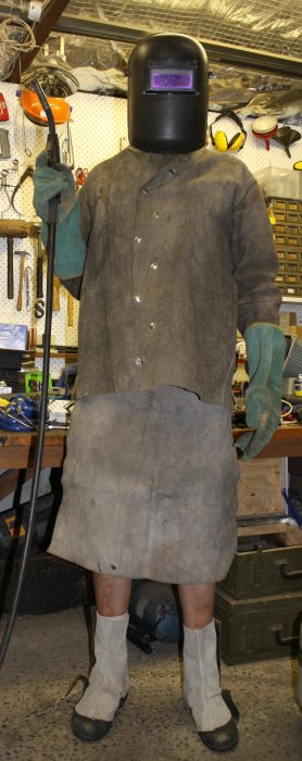 The weather was pretty hot at this time. Full leathers are only bearable for short intervals, but at least they can be quickly removed as soon as the welds are done.
Long pants on the other hand... simply no.
Hence this rather odd sight. Leather Ned Kelly, with bare knees.
 |
 |
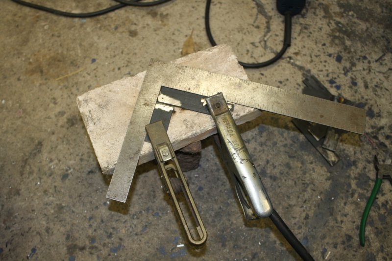
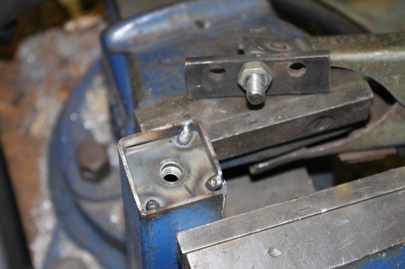
1, 2. How the nut strips fit in the corners, before welding. Using hex bolts machined as semi-countersunk, for centering the bolts in holes to ensure the threads don't bind against the hole sides after welding. Holes are slightly oversize.
 |
 |
 |
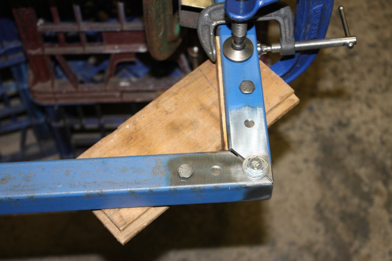
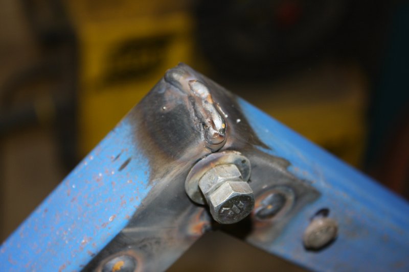
1 - 3. Corner welding.
 |
 |
 |
 |
 |
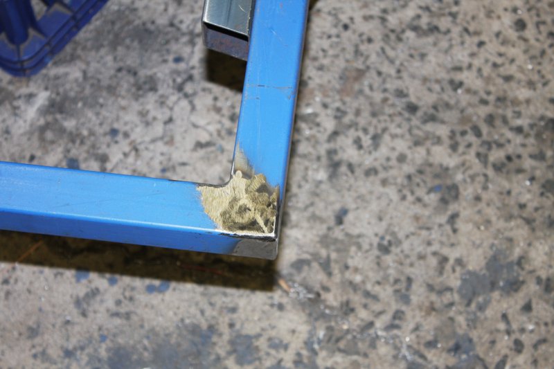
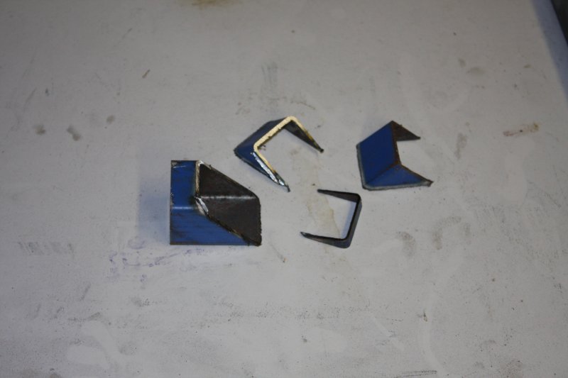
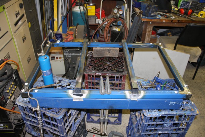
1. When I was cutting the steel I'd optimized it pretty well. These are all the offcuts. But I'd slightly overdone it in one place.
2 - 4. So this corner had a bit of a gap due to cutting the angle too close to the end of the stock. Easily bridged over with the welder. Then grinding neat.
5. I was pretty happy so far. The frame ended up still exactly square.
 |
 |
 |
 |
 |
1 - 3. Making the castor mounting plates. Oh, in pic 2 there's that wooden drill template I mentioned. Thanks to which all the bolts were nicely aligned and could be screwed in by fingers.
4. And now for something I knew wasn't going to go so well. Welding on the cross supports. What happens when you weld to the side of a straight bar? You get a banana-shaped bar. The added weld metal solidifies, then contracts as it cools further. The forces involves are very large, and can bend the rest of the bar.
On first attempt I just clamped the bar to a much bigger beam, that wasn't going to change shape at all. I hoped that would be enough. By now I should know better. Nope, banana-shaped. But now I know by how much.
So the other side I clamped up with spacers, to be bent that amount in the opposite direction before welding. After welding, take off all the clamps, and it's straight! Pity I couldn't estimate it right for the first attempt. A skilled welder would have been able to. I'm not one of those.
5. Anyway, the fix is to use clamps to stress the bent beam opposite to the bend, then heat the bent areas up to red heat. This pic is after it cooled and I removed the end clamps to see if it was straight.
 |
 |
 |
 |
 |
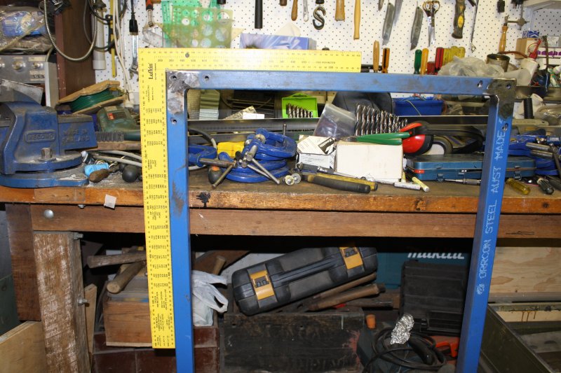
1. It is! Nice and straight.
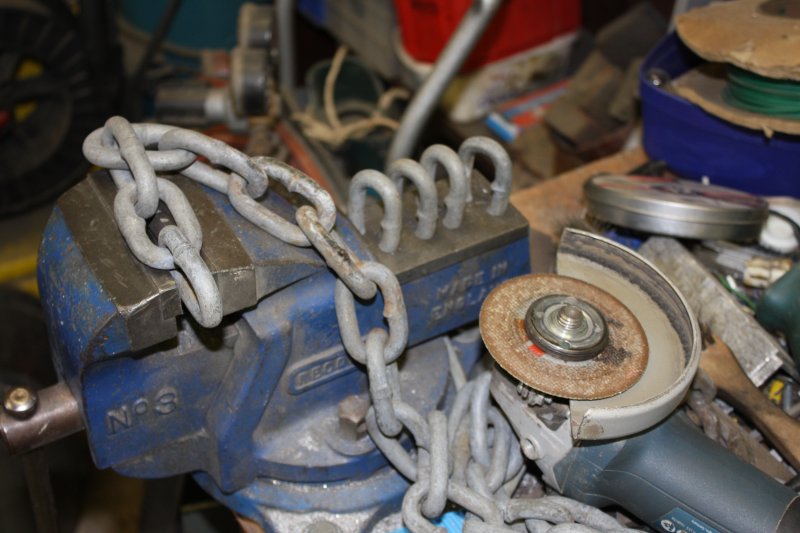
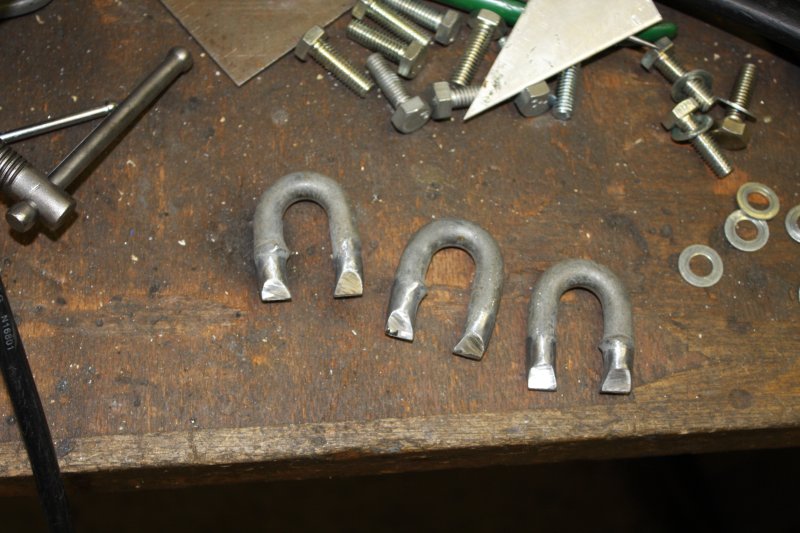
2. The next question was, how would the dolly be pulled around, have things strapped to it, and a ramp attached to either end? I really was winging it at this point. I'd been imagining some kind of clip-ons involving bits of square section welded onto the underside. But messing around with straightening weld-warps in the frame had put me off that idea. I decided to leave the frame alone, and attach mount points via the wheel plates. And the simplest way is to use U loops, cut from some nice fat chain.
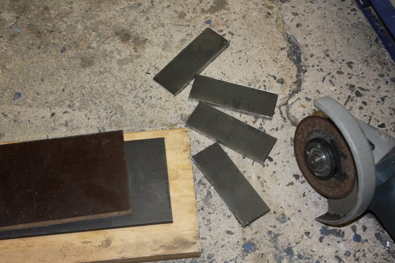
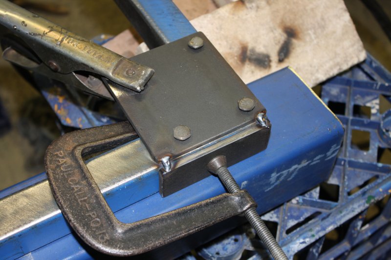
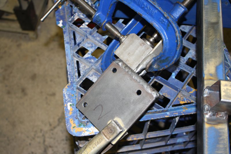
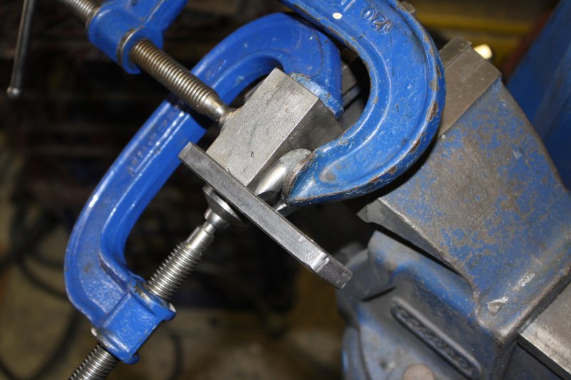
3. The wheel mount plates are cut from 6mm thick steel. Here cutting off some more pieces of that. Have I mentioned how much I love an angle grinder with a thin cutting disk? They cut even thick steel so fast! The dark bit of board was used as a ruler to begin the cuts. Once you have a small groove, the disk is easily guided to stay in that groove.
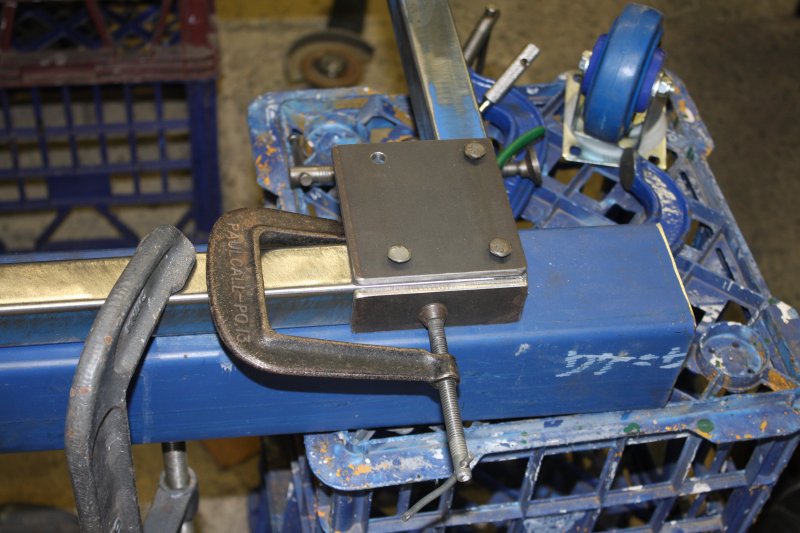
4. Clamping for the tack welds. This configuration wasn't planned, so there was a bit of a gap to bridge with weld metal. Not a problem.
5. Tack welds. Not going to do the main weld while attached to the frame, since it could end up welded to the frame, and/or the frame warped from the heat.
 |
 |
 |
 |
 |
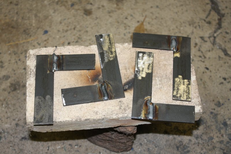
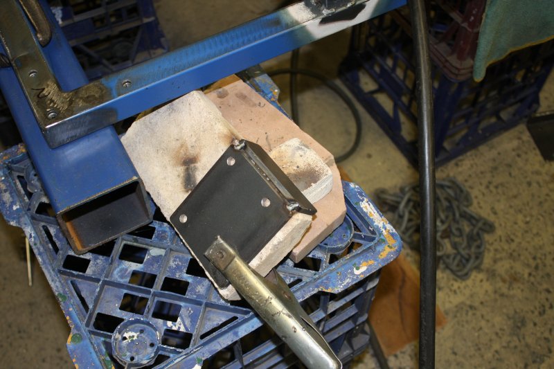
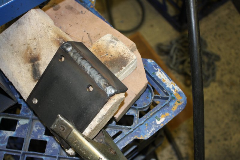
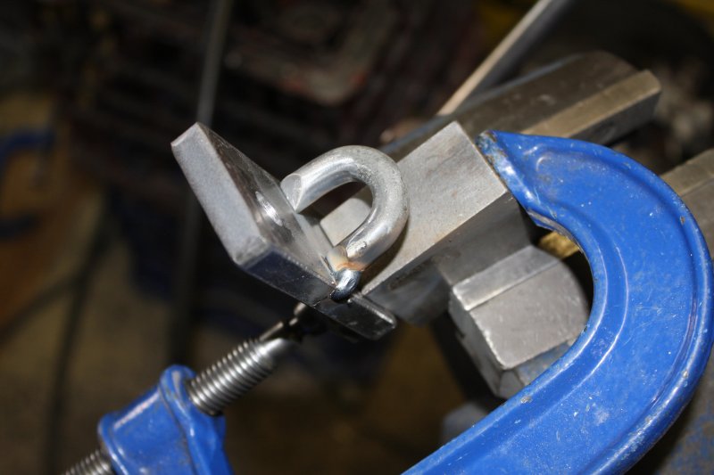
1. A bit of fire brick on the other hand, will have no complaints. Plus I can easily orient the weld for best result. With this thick steel I'll crank the current and wire feed quite high, and zig-zag to fill the space.
2. Done, one pass. (Ha ha, my first attempt wasn't so great. But good enough.)
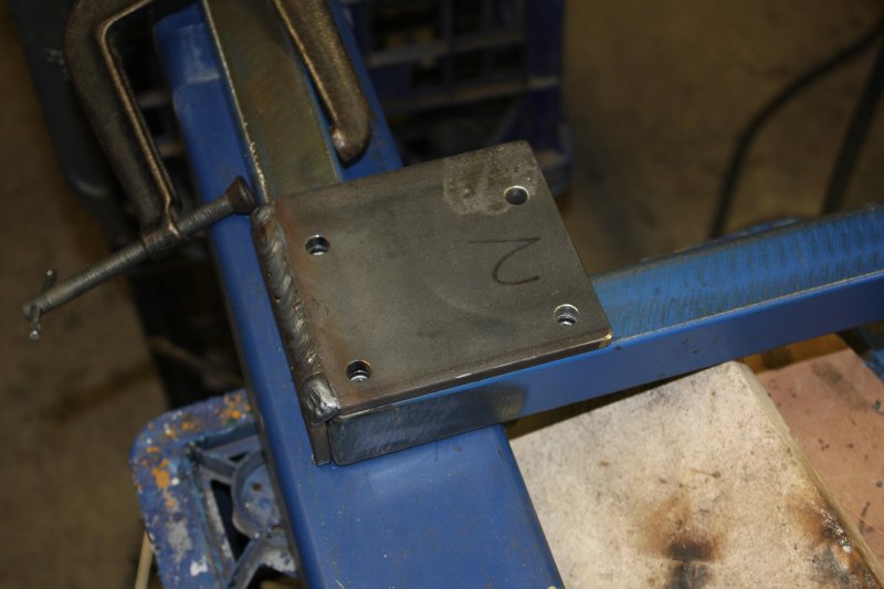
3. Checking fit. Really, what could have gone wrong? But I'm relieved to see nothing did.
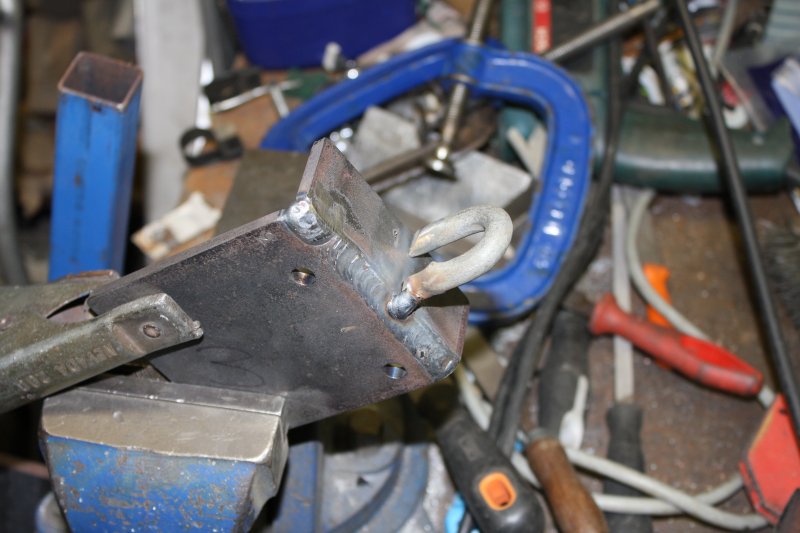
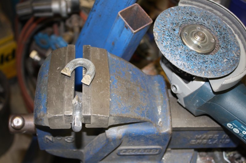
4. Clamping up to tack-weld the loops.
5. Also, after having ground off the zinc galvanizing. Zinc fumes are a hazard of welding, to be avoided.
 |
 |
 |
 |
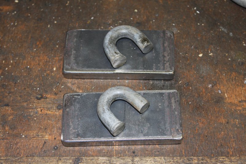 |
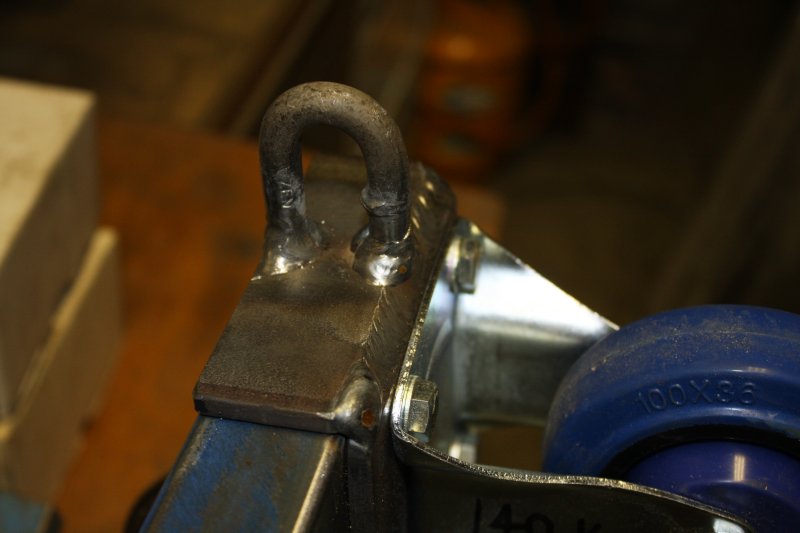
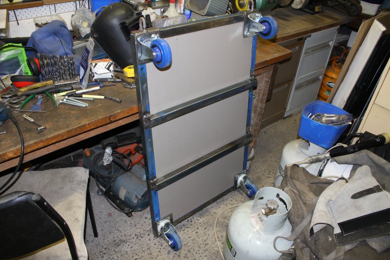
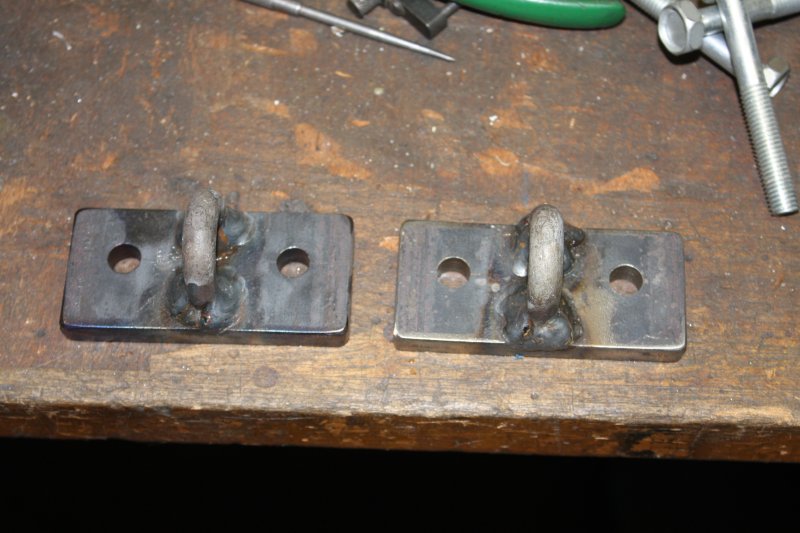
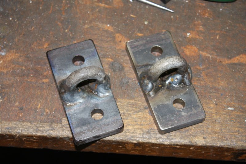
1, 2. Tack welded, and a completed weld.
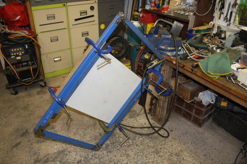
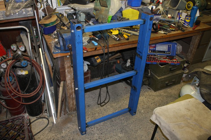
3. The dolly, nearly completed. Well, except that I'd like to paint it. But the date of the trip to Albury is getting close, I still have a ramp to make, and 'paint drying times' just aren't going to fit. So no paint for now.
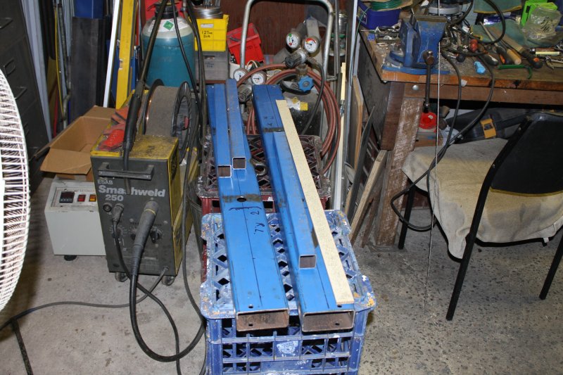
4. As for the ramp... I want it to have plenty of freedom of swing. That means I can't use the same 35mm beam for the ramp sides, since it doesn't fit over the chain loops. What I do have, is the beams from the lathe trolley. I don't mind using them, so long as they can still be used as a lathe trolley in future. A few extra small holes won't matter. Plus multi-purposing these big bits of steel appeals. Makes storing them more worthwhile.
In this pic they are just propped up in place, while I think about how to do this.
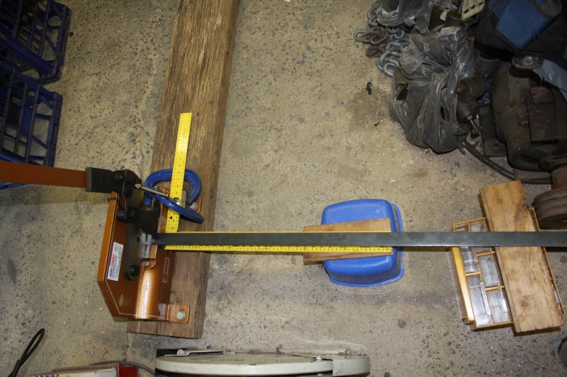
5. Not surprisingly, the answer involves more of that 6mm steel, and chain loops. Except the loops have to be shorter than I'd have liked, so the trailer gate clears them when opening.
 |
 |
 |
 |
 |
1 - 5. These are going to bolt onto the back of the trailer.
 |
 |
 |
 |
 |
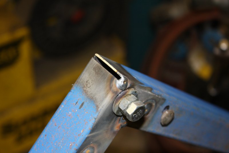
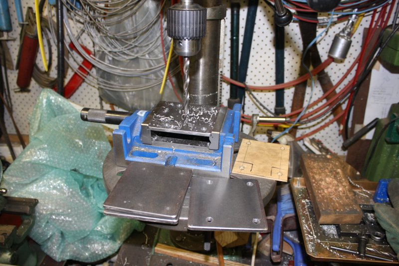
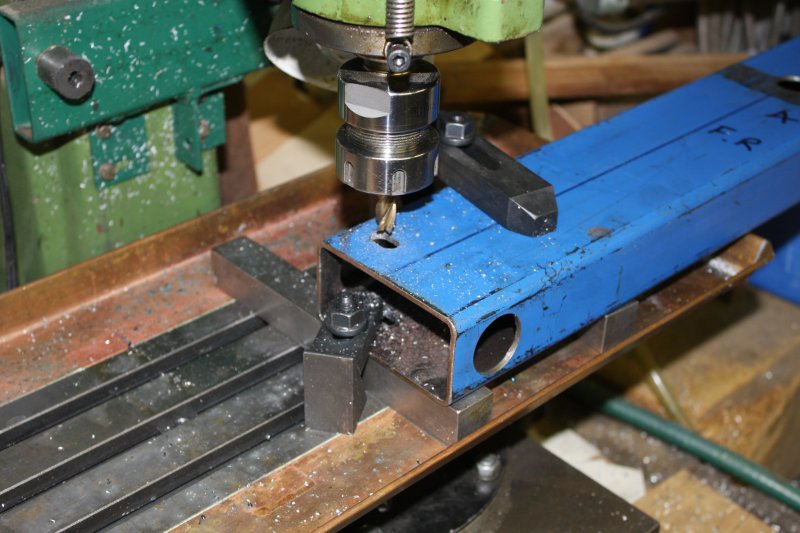
1. A slight annoyance — holes at one end of the ramp had to be slots, to get enough arc or swing relative to the dolly. Too thick to easily file by hand (I know, I tried one), so here's how much clamping was needed for each of four holes, to use the mill. Painful.
2. Three cross bars cut, to support the ramp board. They have to end-bolt to the big beams.
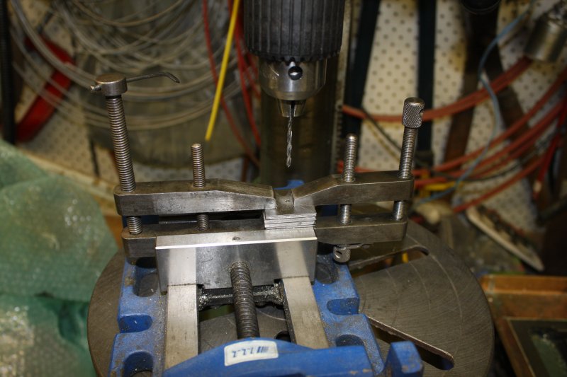
3. So they have to have nut inserts welded into their ends. Here cutting the insert plates.
4. One pilot hole marked and drilled, now clamping all the plates to be drilled together.
5. Like so. For the next few stages they will be kept clamped as a single block.
 |
 |
 |
 |
 |
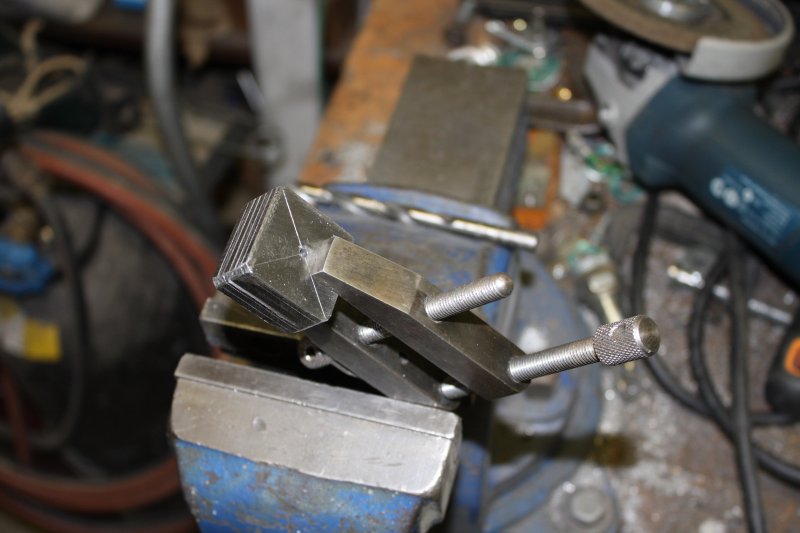
1. During the process of grinding and hand filing the block down so all of them are a nice fit in the end of that 35 mm square steel section.
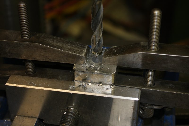
2. Drilling the center hole out. I'd rummaged through my stock of bolts, and found I had plenty of suitable 5/16" bolts and nuts. Still trying to use all those inch-sized ones up, so that's what I used.
3. Welding nuts onto these plates.
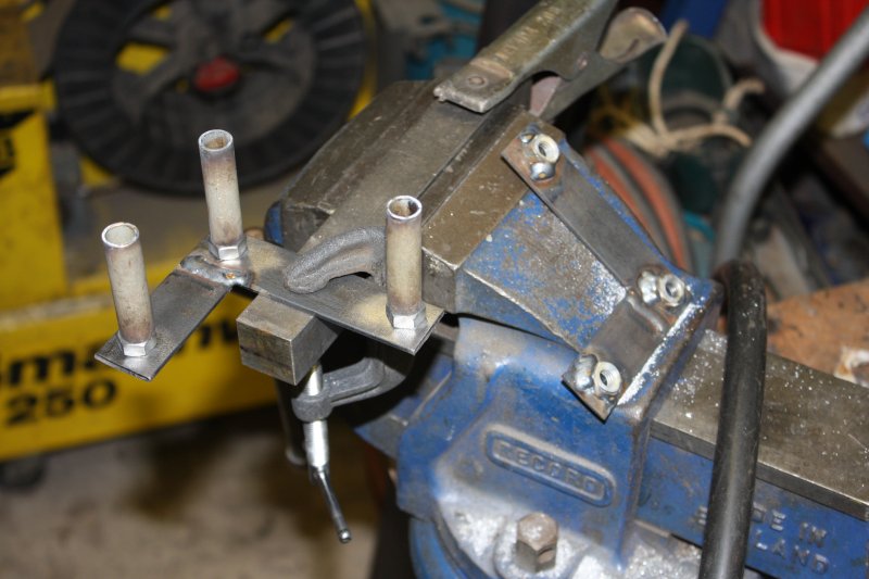
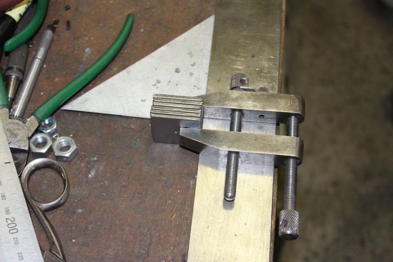
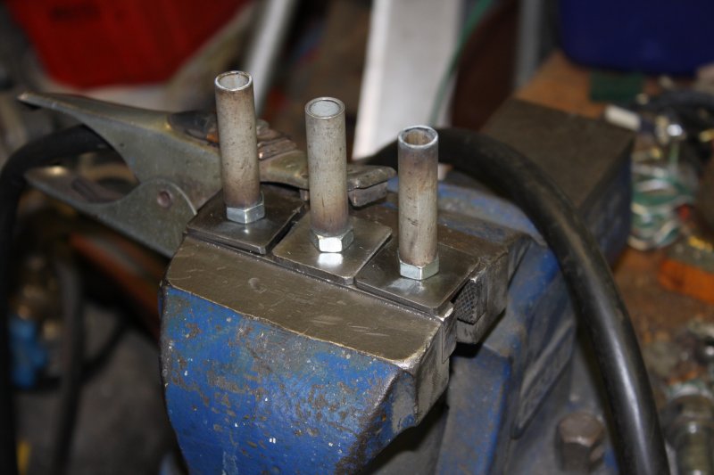
4. They all have to be tack-welded consistently in to the ends of the steel beams. So, this little jig using a bit of scrap. Had to machine down the head of the bolt, to give the welding torch room to get close enough. This allows to tack-weld one corner, then the jig is spun around to do the next.
5. Only need to do three tacks.
 |
 |
 |
 |
 |
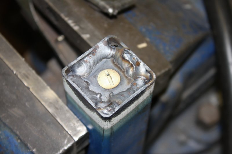
1. Not very pretty welds. A bit difficult, due to needing to get a good thick fillet, while also not melting away the side wall of the square beam. The bolt hole and the thread of the nut underneath are protected from spatters by dropping a small gutter bolt into the hole as a plug.
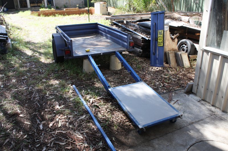
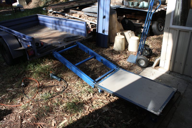
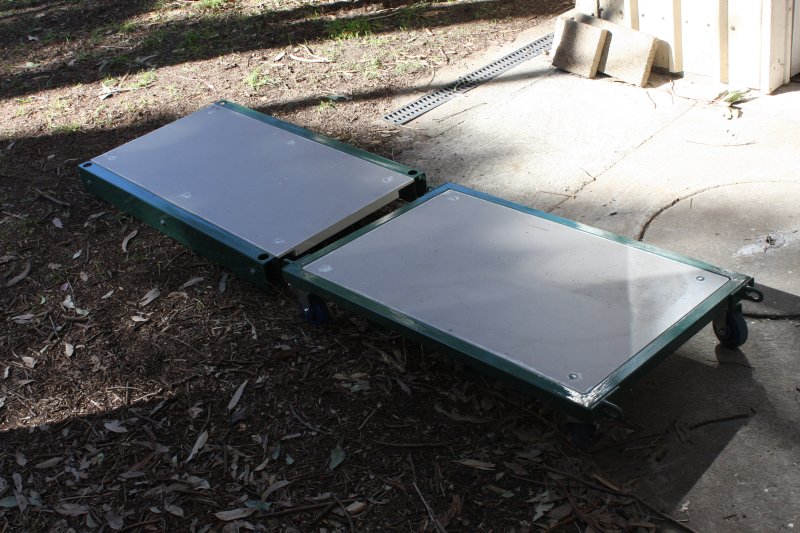
2. The ramp frame assembled. Could not be simpler.
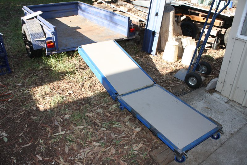
3. Ramp in place. Long bolts are just slipped into the holes and through the chain loops, to clip it all together. No need for nuts on those bolts, though there is room for them.
4. Inset board added. Not yet bolted on or even pushed all the way down in the photo.
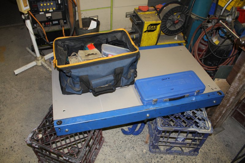
5. The ramp all finished. Also starting to pack up tools for the trip.
By now it was Sunday 8th; I'd be leaving for Albury as early as possible on Monday 9th.
Well that was a typical last minute rush. But at this point I thought everything was all good.
Ha ha.
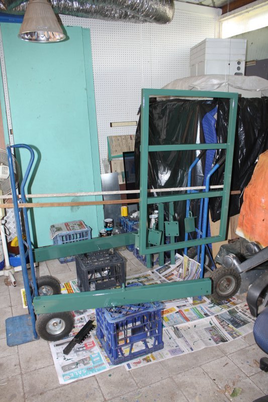
Oh, and three months later... I finally painted it.
 |
 |
 |
Plus temporarily misplaced some bits.