Here's a story about repairing a knob. There are always small chores to do; tedious perhaps, but until they are done they hold up larger projects. And they are not going to do themselves.
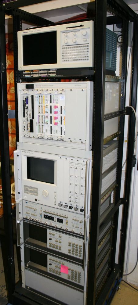
For instance, recently I've been putting together a 'data generation and analysis' equipment rack on rollers.
It's far from finished. Each piece of equipment in that rack has a long 'todo' list — accessories and software to obtain and integrate, things to learn, minor problems to fix, and so on. Before even thinking about using this gear for the intended projects.
From the top down the rack contains:
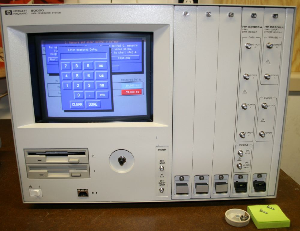
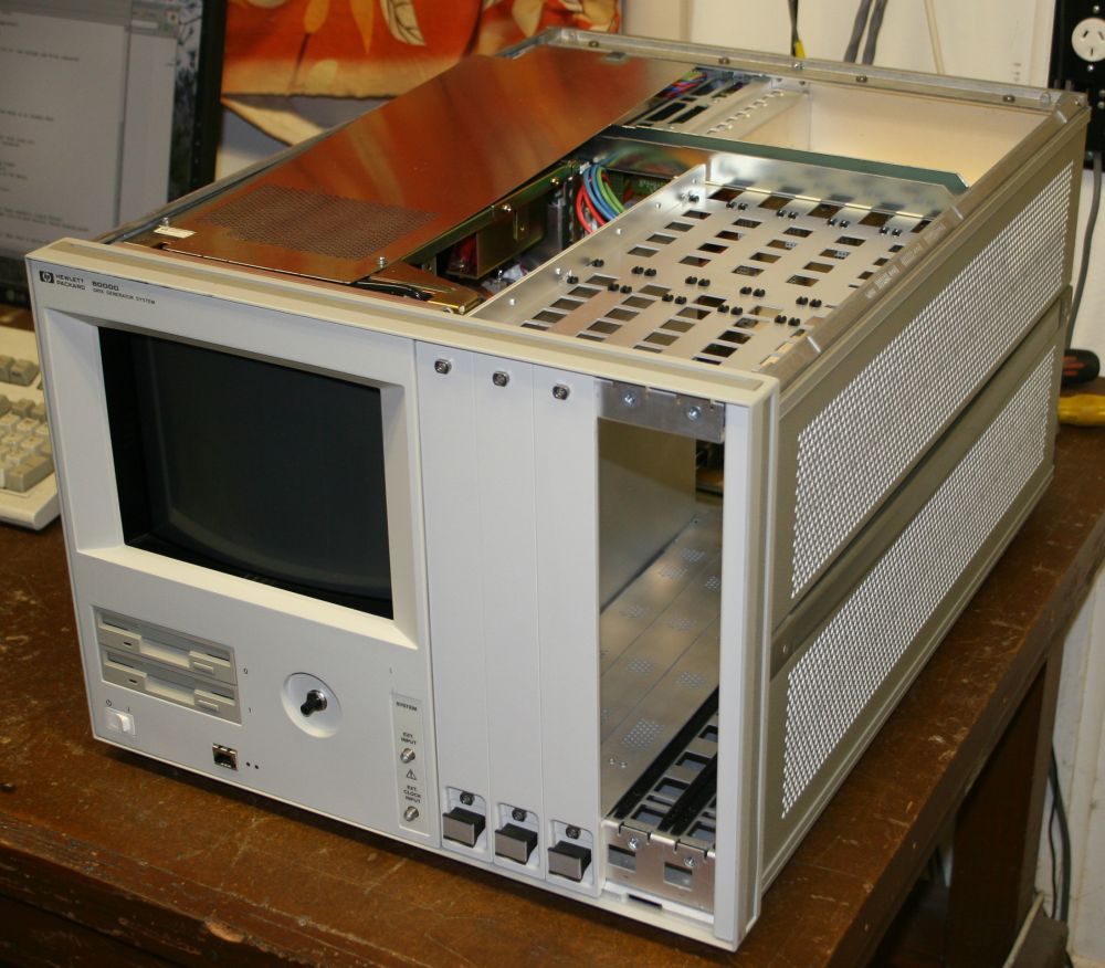
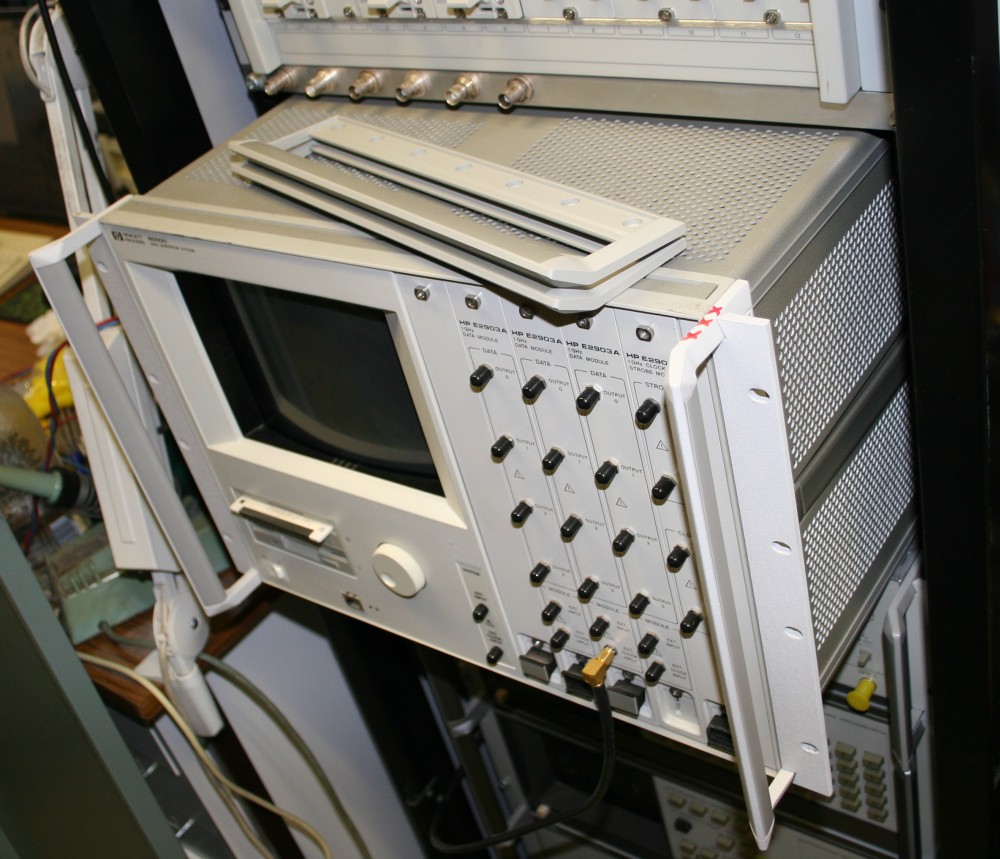
The HP 80000 is a programmable digital data stream generator, with output clock rates up to 1 GHz. It's also physically quite large and heavy. A 19 inch rackmount unit, it's 7U high (about 315 mm) and about 600 mm deep. Boxed up, it weighed 86 pounds.
Before starting to use Shipito in the USA for US to Australia freight handling, I'd not have been able to afford the cost of shipping something like this. If it was sent at the usual one-off rates, it would have cost north of a thousand dollars for shipping. I'm retired, simply can't afford that. But having discovered how much cheaper shipito is due to their bulk discounts from the carriers, things like this are a possibility.
Especially given how remarkably cheap excellent gear like this can be on ebay. I got this one for US$150. Mostly I think because the seller had managed to drop the two modules out of it onto a concrete floor, dinging the SMA connectors and eject levers on the front. I expect there were some choice words said at the time!
Also the front panel power switch was said to fail to turn the unit off. Ha ha, that's a rare one, usually it's 'fails to turn on'.
So I considered I was buying just the mainframe. If the modules still worked, or could be repaired, bonus. I'd found that modules were fairly commonly available, and cheaply — like around $30. So I could replace the damaged ones for little cost if needed.
These are some of the ebay listing photos.
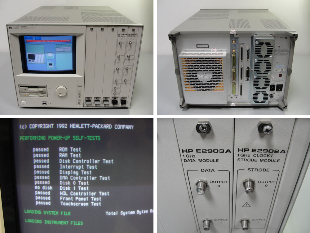
The best thing about this unit though was that it had the floppy disk, and was shown booted. No, there's no hard disk, all the system software is loaded from a floppy disk. And no, it's not a standard PC format floppy. So if you don't have the disk, the unit is 86 pounds weight of useless junk.
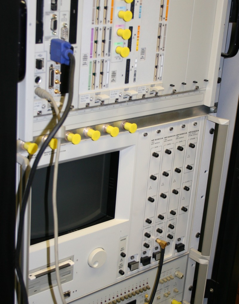
It also has a HP-IB connector on the back - another plus since I'll be controlling most of the gear in my projects via HP-IB bus interfaces from a PC.
At that time I hadn't yet worked out what that plug on the front below the floppies was. Looks like an RJ45 ethernet port, which seemed a bit unlikely. What were those dots next to it? Possibly network activity LEDs?
It arrived, intact. Huge carton, and inside the unit was nestled in thick 'foam-in-place' padding. While lifting it out of the box I immediately discovered exactly how the seller had managed to drop the modules on the floor. It's such a big heavy thing, and there's not much to hold onto. So your natural reflex is to grip it by the most convenient spot — the upper edge of the screen. Then you lift it with that point as the bottom, to best carry the weight. I'd only just started that motion when I realised 'Hey, this is going to result in me lifting it out of the box and carrying it over there to the bench, with the front facing down. And I don't know if the modules are screwed in or not. Stop!"
Ha ha! Well they were screwed in then, but I guess they were not when the seller had lifted it the same way.
On the bench it powered up fine. Yes, it's a touch screen. Or rather, a 'don't quite touch' screen — there's an infra-red beam grid in front of the screen, and you just point at things on screen with your finger a few mm from the glass. So no greasy fingerprints to clean off the glass. It works rather nicely.
Even better, the system diagnostics say the two modules are fully working. I'd been hoping that when the modules were dropped, only the end SMAs would have been damaged. Unfortunately it turned out the seller had managed to skillfully drop them both almost perfectly square to the floor, and almost all the SMAs were at least slightly damaged. That's a pity, and one reason there won't be any scope shots of 1GHz waveforms just yet. SMAs are precision connectors, and merely screwing a good one onto a damaged one can result in the good one becoming damaged too.
Maybe the SMA connectors on this can be replaced? Though I'm aware there's a very high chance that won't be possible since behind that front panel there will be some pretty high tech stuff, to achieve 1GHz data output rate. It's very likely the SMA connectors are projections from some ridiculously unobtainable GaAs circuit block.
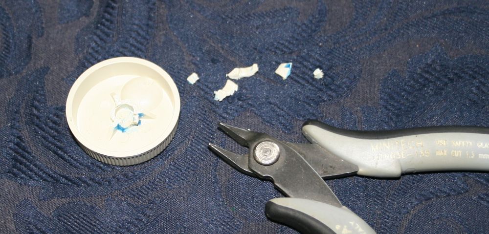
What was really a surprise was discovering that the one moving part user interface control, the spinner knob, is broken. Bad design. In fact it's astonishing to see how badly designed it is. On a machine that must have cost a quite large fortune when new, Hewlett Packard saved a few fractions of a cent on the one user control, by making the molded socket for the shaft very thin. So of course it cracked. In the photo above I was using a steel nut and bit of thin spring metal to hold the broken piece in place while temporarily gluing it. But this wasn't a permanent fix, I knew it would break again fairly soon. Problem was, I couldn't immediately see an easy way to fix it properly. As usual I'd like to retain the original appearance, so screwing any old knob on as a replacement is not acceptable. This problem could be put aside for another day.
The small white 'power switch' it turns out is just a soft power control. And rather than 'doesn't work', it works intermittently. Depending on how you move it. So that's good - a mechanical problem with the switch.
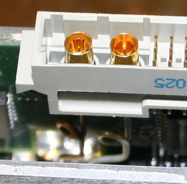
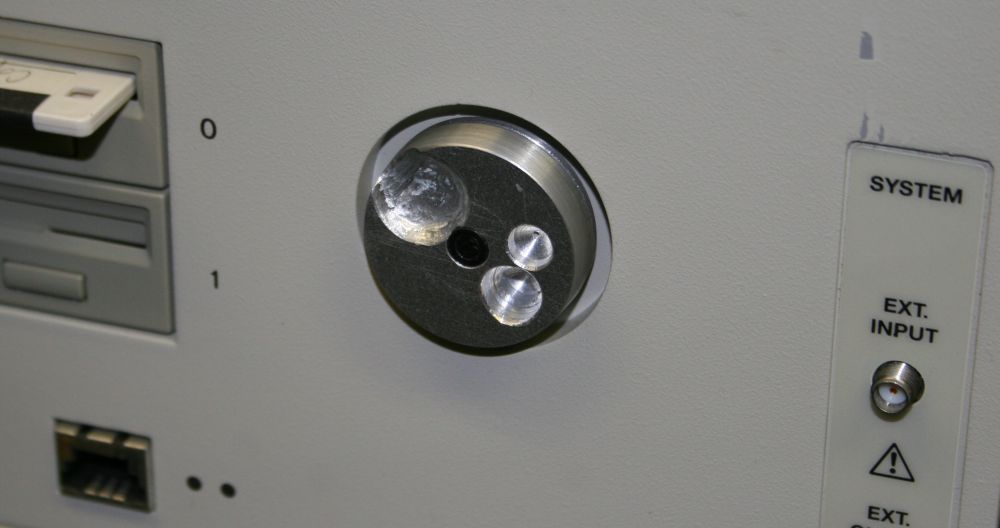
As for the 'RJ45' connector, no it isn't. Trying to plug a standard ethernet cable in as an experiment led to a moment of confusion. Wait a minute, this doesn't fit. Huh? What is that socket then? Looking closely, I'd never seen one like it. Then I wondered about the two dots. Are they really LEDs? They seem to be awfully well made flush with the panel surface, I can't see any join at all. In fact, wait...
It took a stronger pair of glasses and shining a bright torch at an angle to the surface to convince myself. They are just two dots of black paint, on top of the slightly textured beige paint of the panel. Ha ha! What do they mean? It didn't take much googling to find out, and it's interesting.
Back in the mid 1980s, Hewlett Packard saw the need for a high speed serial, low pin count bus, able to string together multiple interface devices like keyboards, mice, knob-boxes, etc, using low cost cables and connectors. They designed the HP-HIL (Human Interface Link) serial bus. This was long before USB evolved, and in many ways HP-HIL was an ancestor to USB. It probably would have been more widely adopted, if HP hadn't chosen to keep HP-HIL as proprietry. They ensured HP were the only source of the ICs needed to implement the bus, and so it vanished into history within a decade. I'd never even heard of it myself.
That explains the two black dots. The connector on the HP 80000 is a HP-HIL 'system end' port, and the two dots are a standard symbol identifying that kind of port. The other 'device' end of the cable uses a similar looking but differently keyed connector, and is marked with a single dot.
Some HP-HIL references:
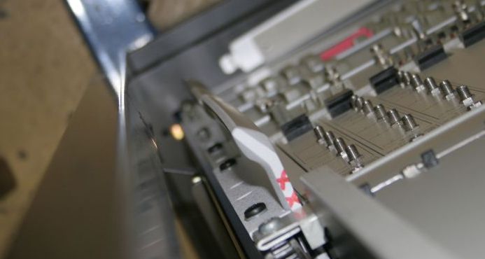
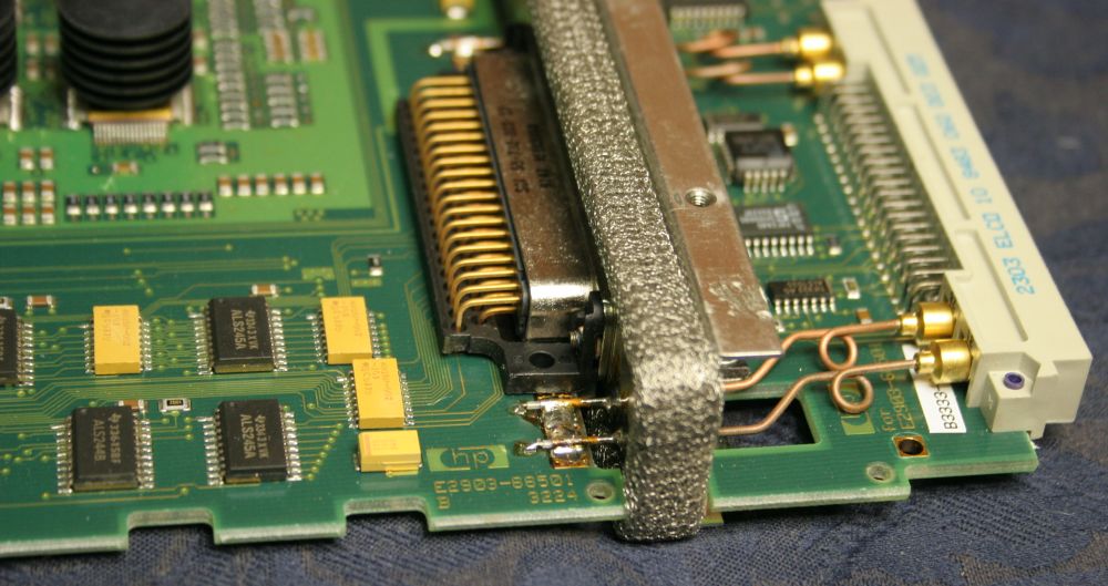
Another problem was the broken eject levers:
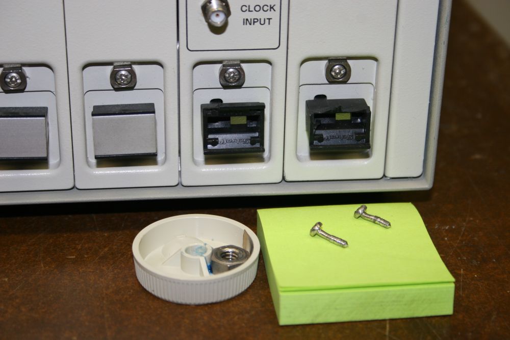
The mangled screws are from the top end of the modules (they were sticking out since they were not doing their job by being screwed in, so they hit the floor first). Those were no problem, since once I got another module I could take two screws from the now unused blanking panel. But the ejector levers, sigh. By Schroff, PN 60817-135, and it seems they are no longer made. Of course. And I know why too — because they are a stupid design.
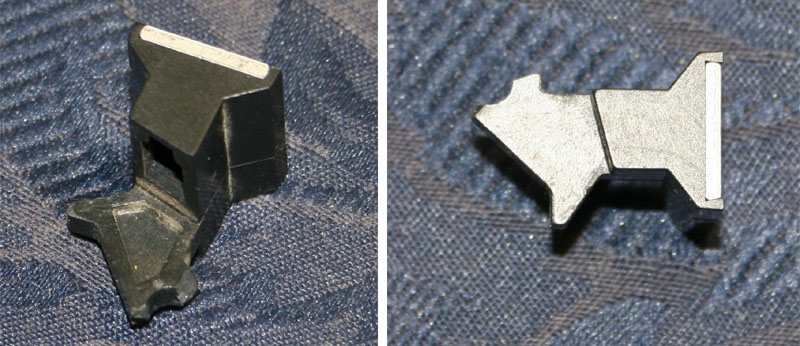
If you push down on them to eject the module they work OK, since all the thin bits of plastic are under compression. But if you accidentally pull upwards on them, even quite lightly, they snap off at the pivot. I already broke one off a replacement module that way, darn it. The one pictured above. I so hope I don't have to resort to hand-making replacements for these. It would be a huge pain in the arse.
Otoh, machined aluminum or brass ones wouldn't break!
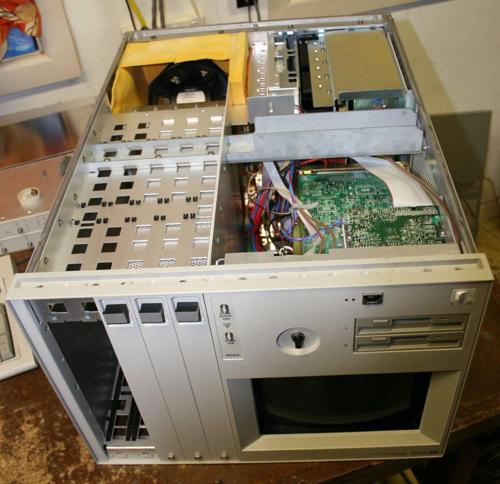
Well anyway, here's a quick teardown of the HP 80000.
The unused module slots have airflow blanking sheets along the bottom of the slots, as well as the front blanking panels.
A thin springy steel sheet on the top of the CRT monitor seems like an afterthought. Perhaps to solve a problem meeting X-ray emission standards?
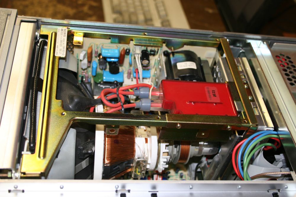
The colour CRT is a standard looking OEM module; Sony model No. CHM-9001-00. Which means there's probably a chance of getting schematics for it.
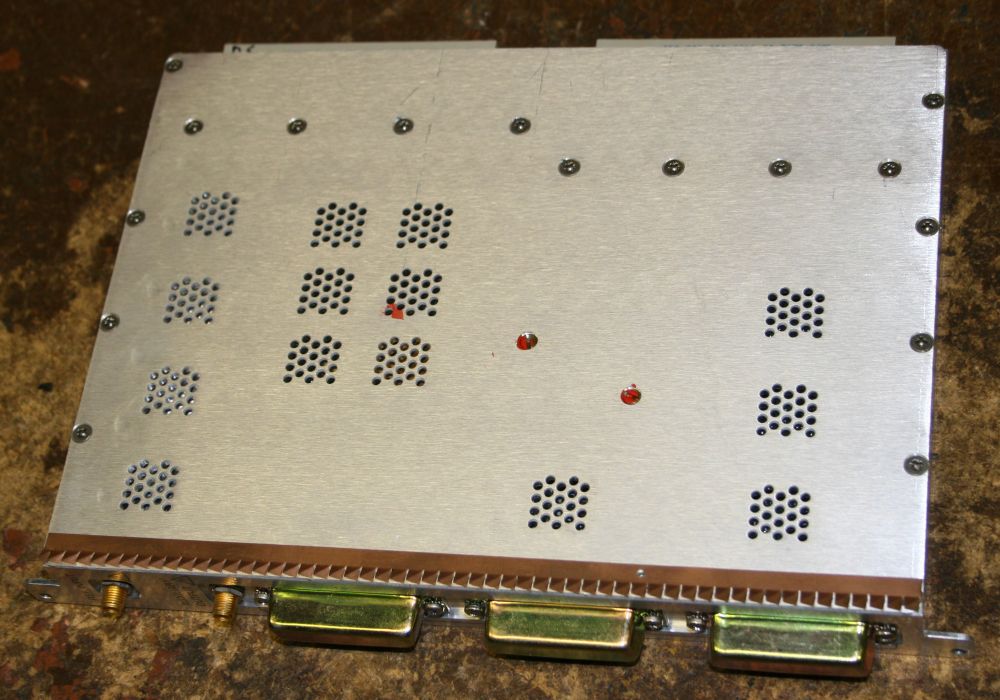
The underside. It was all remarkably clean, with so little dust that I think it must have spent its working life in a cleanroom.
It's also interesting that the airflow path is formed from some soft rubbery foam mouldings. Which probably help a lot in making the unit so quiet. (I'm going to try to add something sound absorbing like this to my Tek TLA 721 logic analyzer, since the large fan in it is very noisy.)
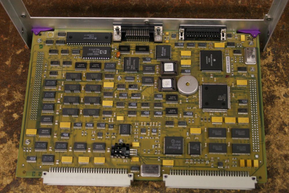
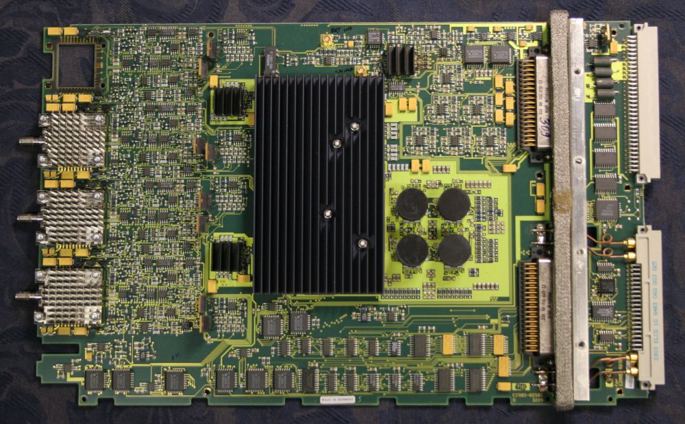
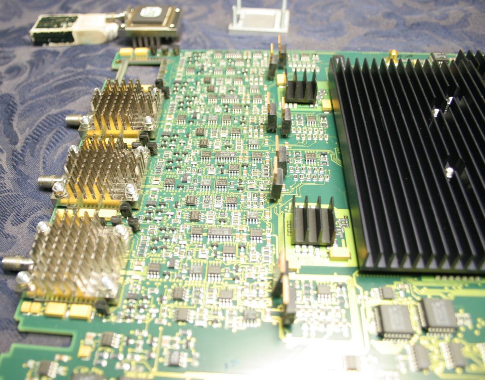
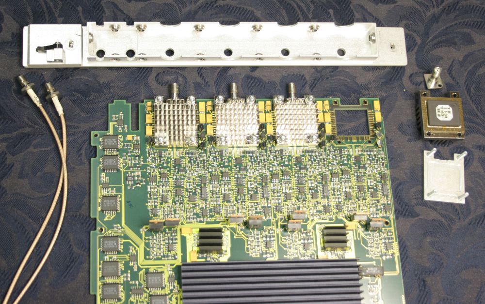
After removing the smaller external fan block from the rear, the circuit modules slide out. This pair of boards are the main controller.

All the really high frequency system clocks generation is inside a very well shielded module. I decided not to open this due to adjustment grub screws that are paint-locked to the cover plate, and could be disturbed by removing the cover. A pity, I really wanted to see inside this.
The three blocky objects at the bottom of the photo are RF shields screwed down over rear panel connectors.
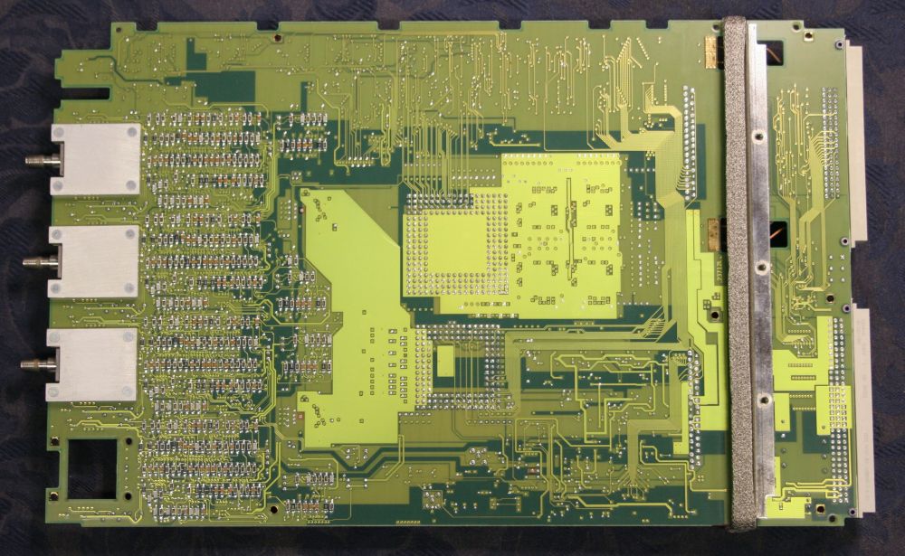
Connections from the system timing module to the system backplane.
The coaxial connectors are wired with very tiny coaxial hardline, that has strain-relief loops.
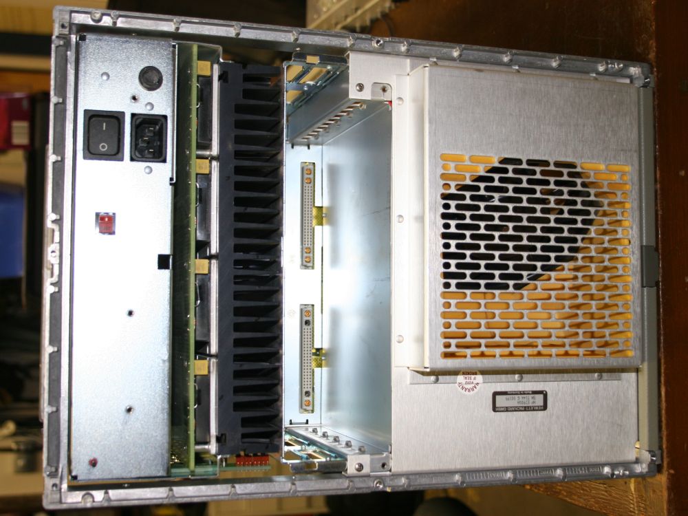
Quite a lot of the internal space in the system is used by the power supply. Considering how warm the data generator modules get in use, despite the strong forced flow air cooling, that's not surprising.
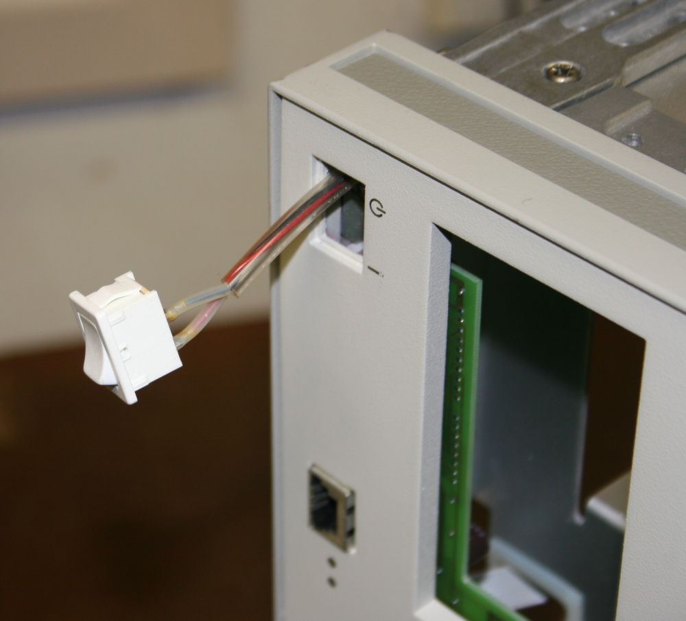
And so to the faulty switch, which was a bastard to extract. Even with the floppy drives removed it was still very difficult to get access to the switch side tabs, to push them in and release it from its mounting hole.
It's obviously not switching much current, but from the insulation it would appear to be at mains potential. Later measured — yes it is. Unsoldered it and sure enough it doesn't work. Mostly open, but shaking it can result in closed circuit. Ah ha, I know exactly what's happened here.
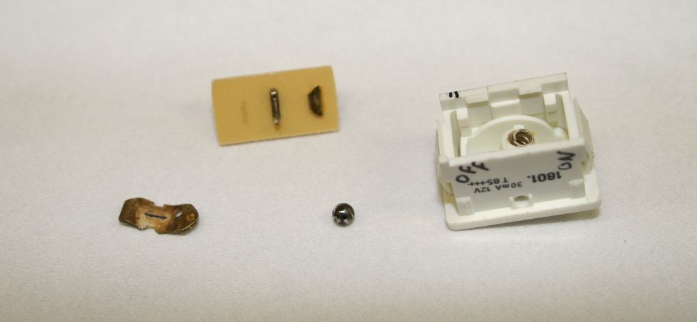
It can be snapped apart, and as expected the metal 'see-saw' piece had worked loose from the center pin retainer, and was floating around inside. Common problem with these. I think it must happen as a result of people flicking the switch rocker too fast, and the piece bounces free. Or something like that.
Anyway, a quick clean of all contact surfaces, a tiny dab of suitable grease on the ball, and after snapping it all back together it works fine. Now the machine powers up and down correctly.
Incidentally, during all this powering up and down I made sure to keep that floppy disk out of the drive. Since I have one copy and it is crucial. Do I trust the designers to have ensured the drive never puts current through the write heads during power transitions? No, I don't. Considering that on IBM PCs, leaving a floppy in the drive during power cycles was very likely to result in bad sectors. So with this machine when I want to power it up and boot, the sequence is: 1. Floppy in slot but not pushed in. 2. Power on. 3. Count to 2, push floppy all the way in and close door. 4. System boots from floppy. To power down, remember to remove floppy disk first.
Well that was the mainframe done, except for the knob and the ejectors. Other jobs needed attention, and I still couldn't think of anything easy to fix the knob. So the system got slid into the rack and left for a while. Later I did manage to find a new-old-stock set of HP rack brackets and handles for it, which was amazing considering it's so large. I'd never seen a set of 7U high handles before. This is what they look like in the original packaging:
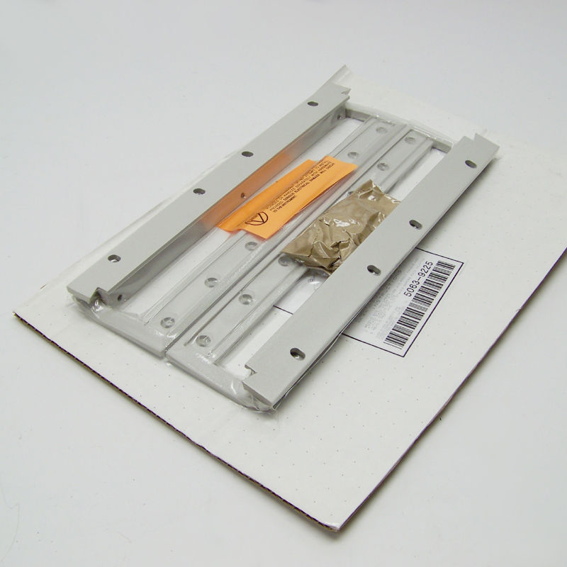
They'd sat in the USA at the reshipper for a while, for consolidation with other items. Then when they arrived I was busy with other stuff and didn't mount them on the HP 80000 for a while. Even when I opened the pack and got ready to attach them I didn't notice anything wrong. The left hand one went on first, and was fine. But the right hand one... As the screws tightened I realized hey, this isn't right. It should be loose, loose, loose, then suddenly become tight. But instead it's gradually getting harder to turn. So finally I paid attention to the assumed straight handle body. Oh. It's not straight at all, it's somewhat banana shaped. And also has multiple other bends.
You can see it in the photo if you look closely. The rear one, flat against the cardboard. See it?
It's very odd. There is no trace at all of any pressure or impacts marking the cardboard. Also the multiple planes of the distortion can't have resulted from simple forces acting on the stiff metal. Besides, this diecast stuff is really brittle - it would have snapped before bending like this.
The conclusion was, it was pulled out of the casting mold while still hot enough to warp a little under its own weight. Then through the entire process of cleaning it up, painting and packaging, no one noticed.
Screwed onto a bit of gear in a rack though, it really obviously didn't line up with the other handles. As it was it simply wasn't acceptable, as it looked really terrible. So I figured I could either throw it away and try to find another, or attempt to straighten it. Even though it would very likely crack, if it didn't I'd be happy. So, in the vice, tapping it straight with a hammer. The lower end straightened up enough, but the upper end (which was more bent) cracked part way through when very nearly straight.
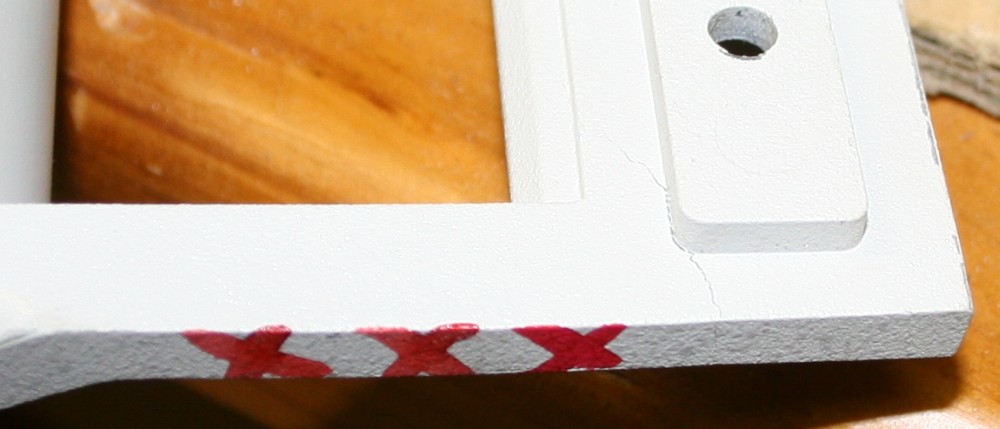
I'd emailed the seller, telling him about it, not his fault, I wasn't complaining, just asking if he happened to have another one I could buy. Nope, but he sent me a full refund which was very kind of him. I'd already given + feedback. The upshot is, the rack bracket does the job of securing the unit in the rack, while the right hand handle is for appearance only - if I tried to lift the unit by the handle it would snap off.
Red "XX" means 'not a handle'.
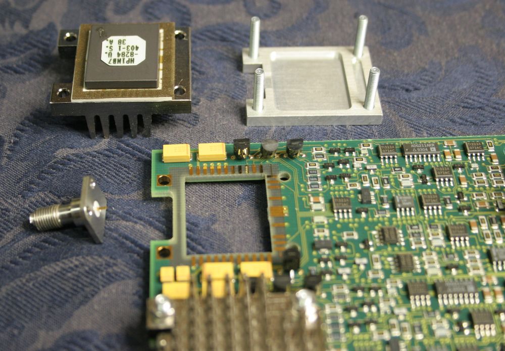
Most of this time I'd been working on other things like some building work. Still not getting much in the way of ideas for how to fix that damned knob. But I did get a spare moment to take apart the most damaged module, the HP E2903A data generator. I really wanted to know whether those SMA connectors could be replaced.
Yep, as expected, the connectors are directly attached to 'magic blocks'. In this photo I've already removed the uppermost magic block (top left), since it's the one with the totally trashed SMA connector.
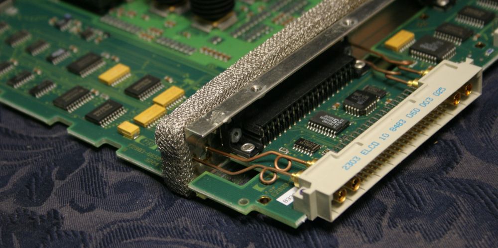
Notice the RF shield bulkhead at right. All signals going through this have ferrite low-pass filtering at the bulkhead, except the few mini-hardlines. The bulkhead also has a springy mesh RF gasket all the way round it, that seals to the outer casing.
Underneath. It's a busy board. I wish I could get schematics of these modules and the mainframe someday, but I seriously doubt I ever will be able to.
Closeup of hardlines.
Ditto. Notice there are no tracks from those hardline PCB pads, on either side of the board. The traces will be on an inner plane, with carefully controlled width and spacing to ground planes above and below, to produce an impedance controlled stripline.
It was quite a surprise to find that the magic block is only connected to the PCB via a thin sheet of elastomer, that appears to be impregnated with specks or threads of gold. So it's like an LCD contacts strip, except working up to 1GHz.
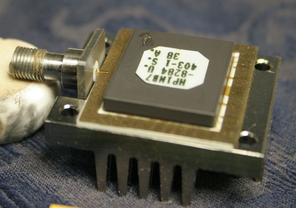
The output SMA is connected to the block the same way. Cool. It means the SMAs are very easy to replace — if only there was some way to get replacements other than just buying more modules. But I suspect that buying a module for somewhere between $30 and $100, giving 4 of these custom SMAs, would be cheaper than buying them new from HP. If HP even made them any more which is unlikely since HP as such no longer exists.
The Magic.
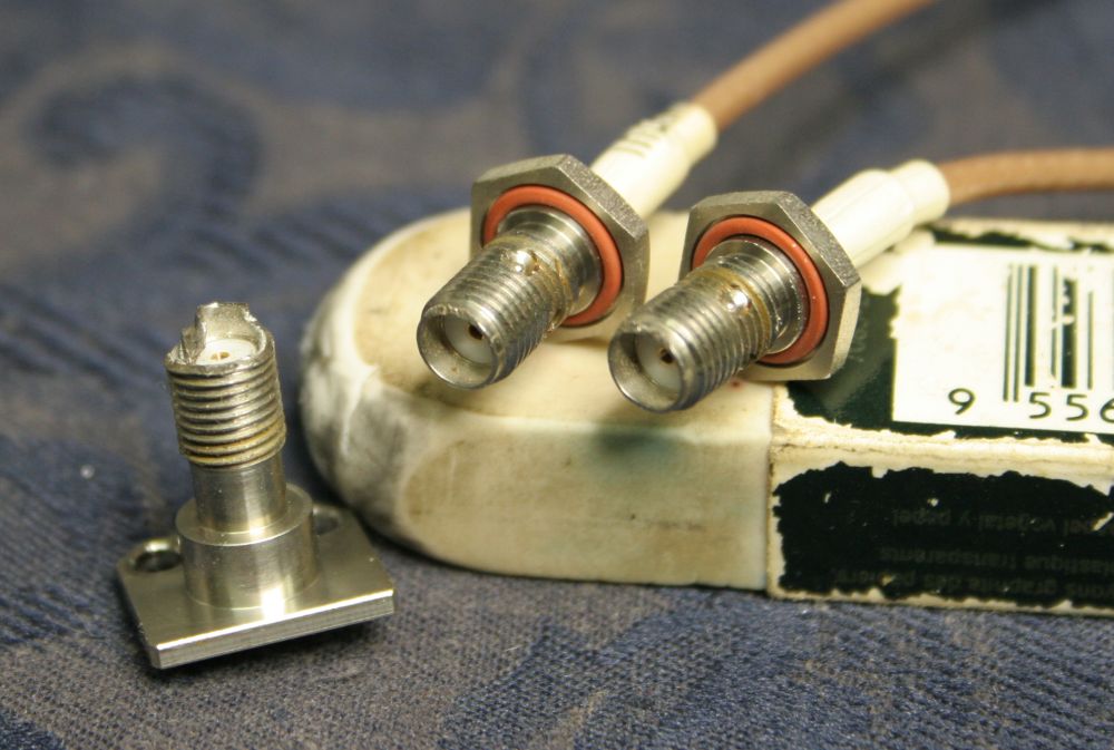
Not so magical. Three very dead SMA connectors. Even the ones on the cables are rooted, despite that its hard to see the damage. To achieve a correct impedance match, the outer rim of the connector has to make good contact with the mating connector all the way round the circumference. Also any imperfections and scratches will tend to distort and strip the gold plating off the rim of a mating connector. Which will then damage any other connectors it is screwed onto. Dinged SMA connectors are like a contagious disease.
To keep connectors clean and scratch-free they should be kept in dust covers when not in use — so I have a bag of the molded SMA dust covers on the way. Even screwing two connectors together should be done carefully — only the nut should be rotated, while the two connector bodies are held stationary against each other. If the mating rim faces are rotated against each other while under pressure, it can spall off the gold plating or even damage stainless to stainless contacts.
Lastly, for repeatable electrical characteristics the nut should be tightened to a measured torque, using a miniature torque wrench like this:

Utica Torque Wrench, Size A with 5/16" spanner. See also Wiki on SMA connectors
Excellence in every respect except one. That ejector lever is rubbish. Top left here, you see the screw pivot point. Where it breaks off if you look at it wrong.
But, finally I'd decided how to fix that broken knob. I bet you thought I'd forgotten what this story was about.
I'd been hoping I could think of something super simple, that didn't require any work. Oh well.
This was the best I could think of, despite it being a ridiculous amount of effort for what it is.
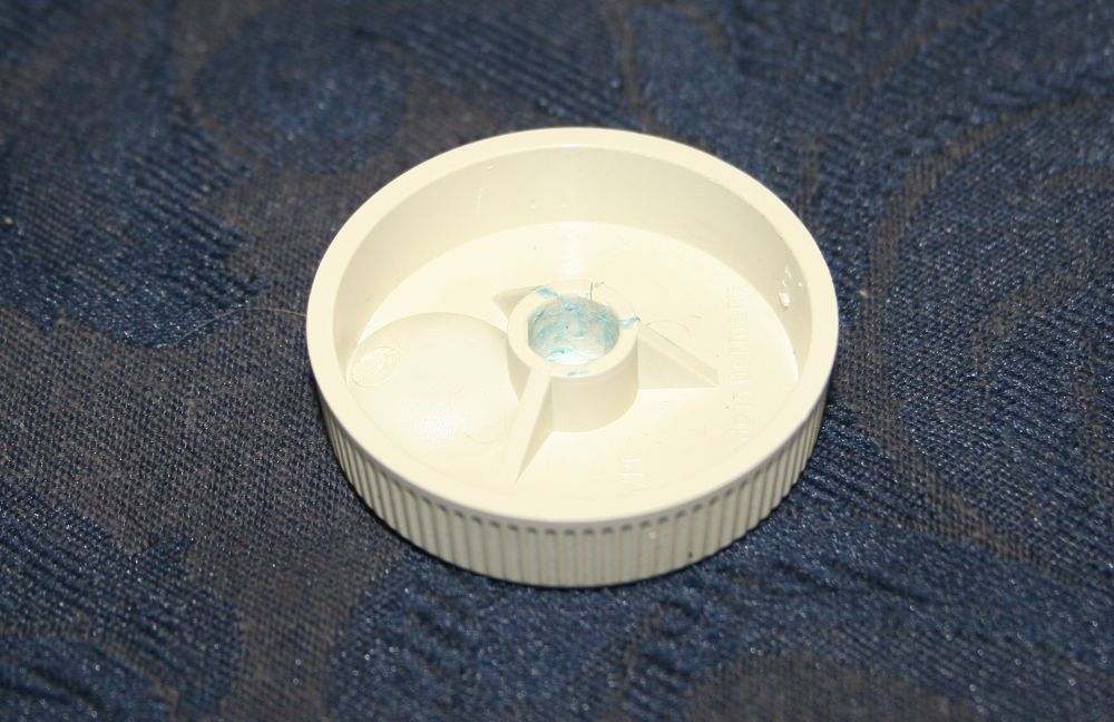
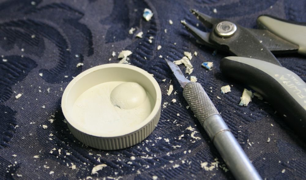
The broken knob. The blue glue is plumber's glue for PVC pipes. It doesn't work so well on this plastic (which I think is ABS, not that I know what that really is.) It had already started to get loose again.
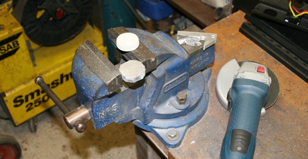
First step; rough cut a piece of scrap aluminium to a disk.
Now say goodbye to that stupid thin shaft mount molding.
All gone. Good riddance.
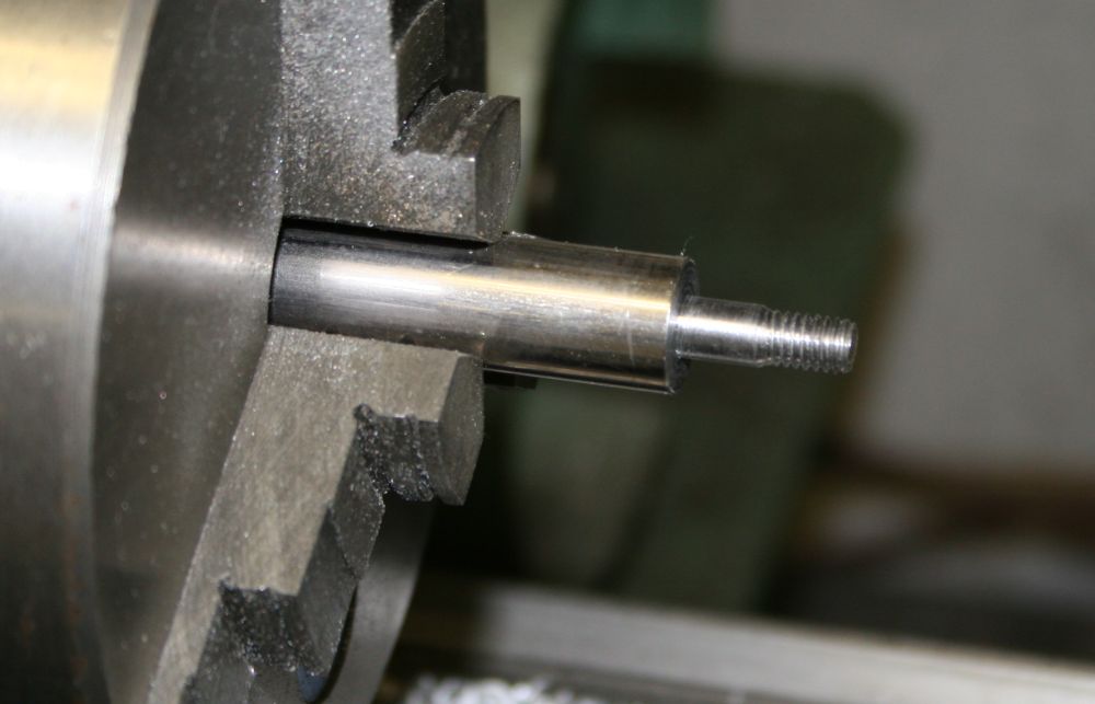
Make a spindle on which to machine the aluminium disk. I'd already drilled the center of the disk to a good press fit of the shaft the knob sits on. This spindle is a press fit to that hole.
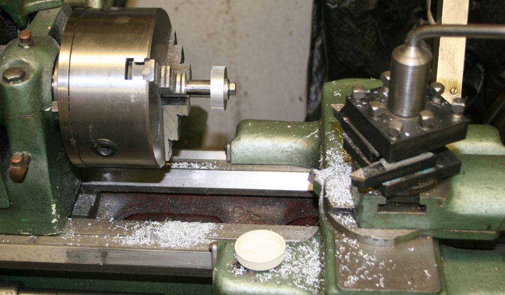
Starting to turn it down to size. The inside of the plastic knob has sides at 4.5 degrees slant.
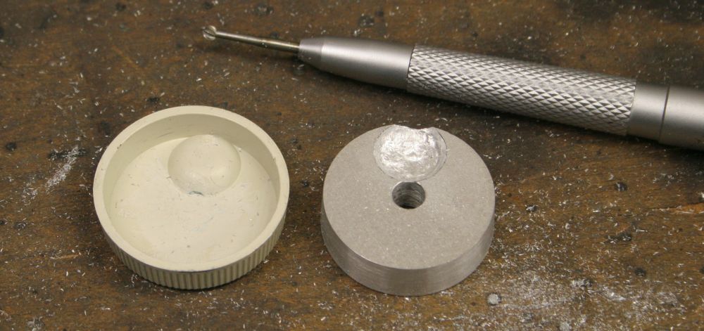
It also has this awkward bump, for the finger hole on the outside. Apart from drawing a circle outline of the right size, the rest of the matching recess in the aluminium shaped by eye, using an engraver.
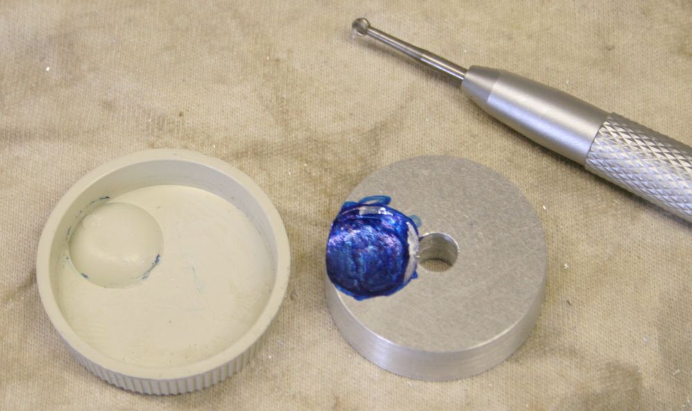
Finally a little 'try and see' using blue ink to transfer contact points to the plastic, then cut away a little more metal where needed.
A tapped hole, for a securing screw.
These grub screws. M3 thread.
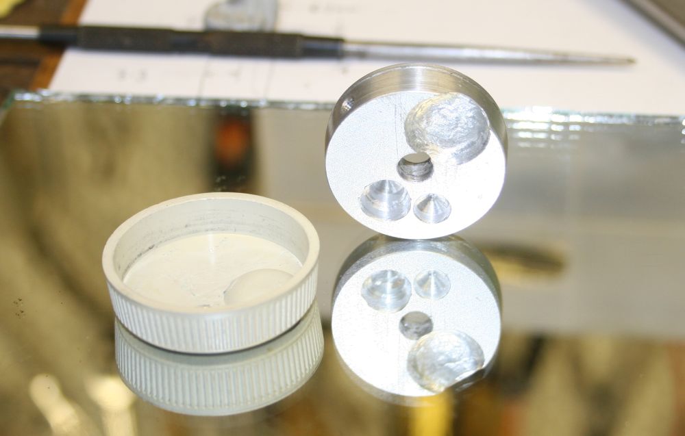
Of course this isn't called a spinner wheel for nothing. The shaft it mounts on has very little friction. Which means if the knob isn't weight balanced it will move on its own when released. That could be quite annoying when using for item selections on a touch screen that you'd be using the same finger to point on. So this is balancing the metal disk, by drilling metal away until it doesn't want to roll to one side on a sheet of glass.
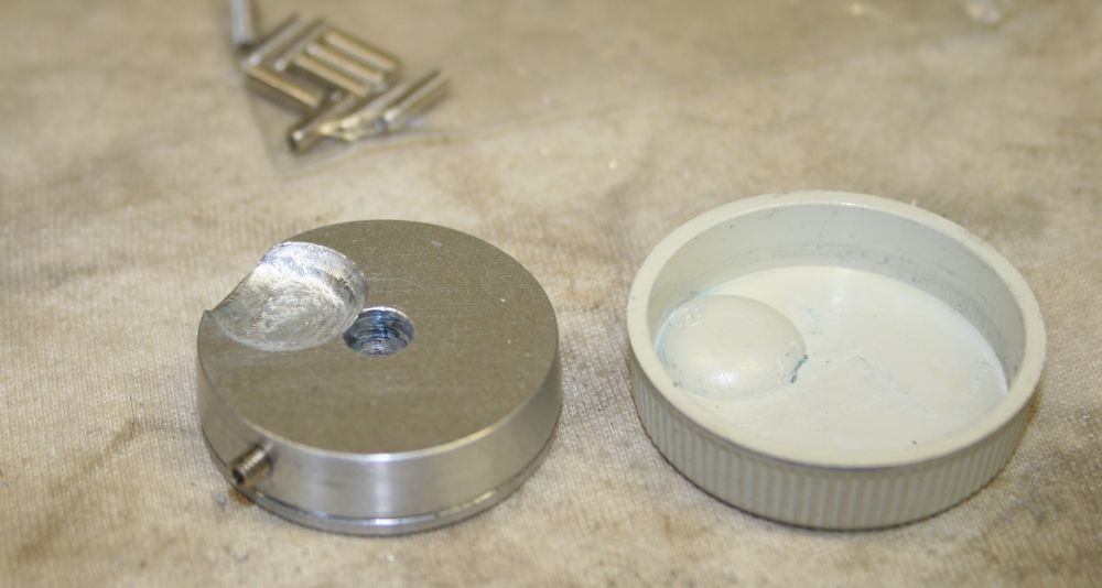
Final mounting. Yep, it's position-neutral, so my improvised balancing worked.
I'd considered the idea of making the disk a tight press fit in the plastic knob shell. But decided against it since the last thing I want is for the whole knob to split. So it's a nice fit but not tight. To hold the knob shell on, a couple of small dabs of silicone glue.
It has to be not too hard to remove in future, since the securing grub screw can't be got at until the knob shell is removed. I didn't want to drill a hole in the side of the shell.
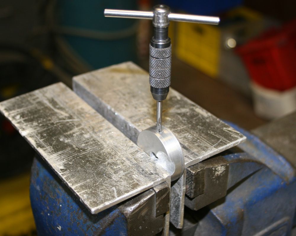
Holding the shell in place while the glue dries. KNOB DONE!
Incidentally that floppy is a copy of the original that came with the machine. I couldn't find a 'disk copy' command in the system (though I see now reading the horribly badly scanned manual I found online that there is one) but it does have an obvious command to copy files. You have to type in the destination file name, but it works. No, a PC cannot read them. One more chore is to figure out a way to get the file data to a PC, to archive it. Maybe that has to wait till the HP-IB to PC interface is working.
There are also some ROMs on the system main board that have to be read and saved. Not sure if they are flash or masked ROMs.
Well that's a coincidence. Because I've noticed that a lot of scanned old technical manuals have this problem severely. And the manual I'd found for the HP 80000 is a prime example. With actual corrupted text, caused by exactly that problem - incorrect patch substitution.
The whole idea of text compression by fuzzy-matching fairly large areas of the image and tokenizing them, is one of the more retarded things I've seen in recent years of computing science. I can't believe anyone ever thought this could be a good idea, or didn't notice the screwed up document scans that result.
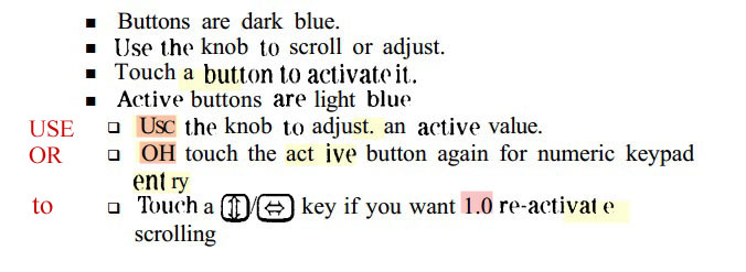
Here are some examples, from the HP 80000 manual at http://www.artisantg.com/info/agilent_80000_manual.pdf
Colour hilighting and comments are mine.

You can tell immediately when reading a text that's been compressed using this awful algorithm. It looks like some kind of ransom note made of pieces pasted together. Because it is pieces pasted together. From different places in the original document. The algorithm doesn't know about words, only 'patches', so it often breaks words into different looking style chunks, as above.
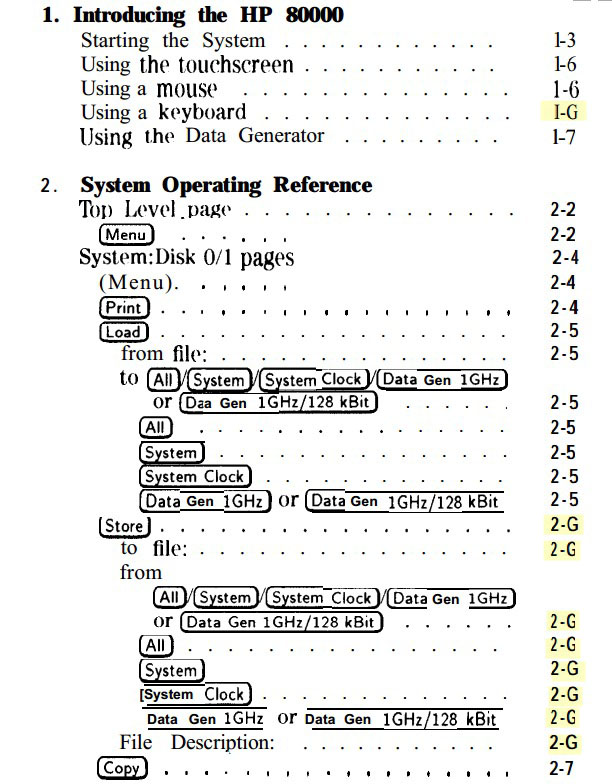
It often makes substitutions of similar-looking characters and numbers. This can produce actual factual errors in documents, that can be a lot more subtle and even dangerous than the simple 'G' instead of '6' example shown above.
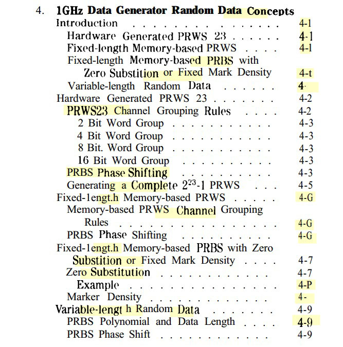
Really it's just awful. The constantly shifting type face, bolding and alignment, the obvious errors, the subtle errors... it's both painful to read, and also you don't want to because the suspicion grows on you that it's going to be full of errors and you are probably wasting your time reading it. I can barely believe anyone would dare put this rubbish online. Didn't they even glance at it after scanning?
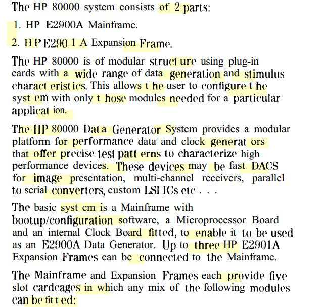
Page after page of this attrocious rubbish. It should be some kind of crime.
Nothing can produce vast volumes of garbage faster than unsupervised bad software. This is what you get.
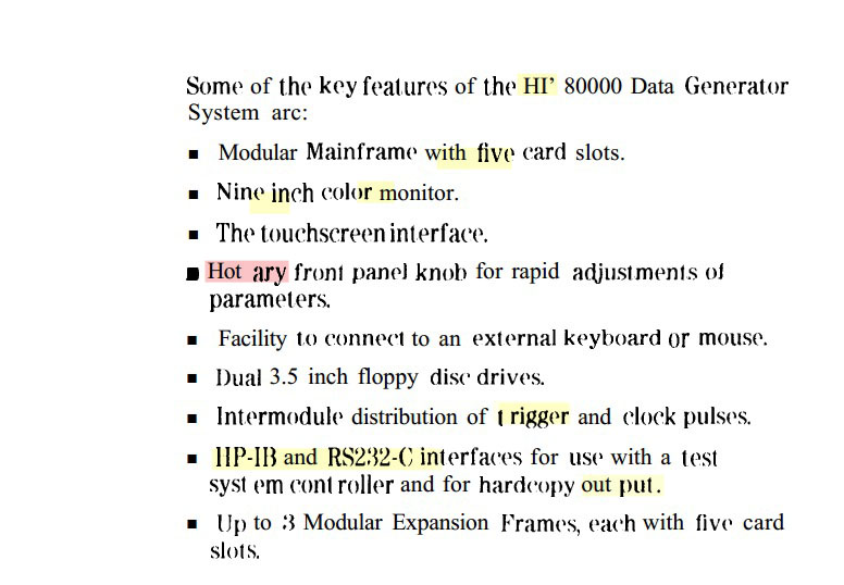
"Hot ary" instead of Rotary. So funny.
Good grief.
Please don't ever use JBIG2 compression schemes.
In this case the so-called 'scanned manual' online is almost worse than nothing. I still have to find and buy an original paper copy, but instead of it being just another shopping list item, I'm angry about it.
Further discussions:
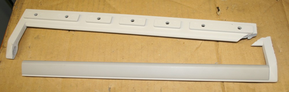
Hardly any visual difference; now they match the handles below exactly. But peace of mind - I know it isn't going to break off with any slight force. This is the crack in the old one:
And this is what happened when I gave it a fairly light tap sideways with the palm of my hand.
Even better, originals of the HP 80000 manuals turned up! Not here yet, but they are on their way.
It's a shame it's not possible to burn a PDF file. Because I sure feel like burning that revolting JBIG2 encoded pdf manual. Oh well. I suppose it's better to keep the file as a bad example, for an article I'm writing on scanning techniques.
Later the manuals arrived:

In contrast to that horrible JBIG2 image compression, here's what the table of contents actually looks like.
