Lately I've been accumulating a few problems, of the 'things I want to do, but don't have the means' kind:
- The microscope illuminator project is wedged, due to a: Couldn't find suitable small cheap lenses for the 10W LEDs, and b: The structure for holding optical components to focus light from multiple sets of LEDs down to one small aperture, is complex. Enough to be daunting to attempt by machining aluminium.
I recently obtained some hopefully suitable lenses, but the structure... It's as if I'd need to resort to 3D CAD and a way to make a complex shape from the plan. - I'd become fed up with the sorry range of choice in (would you believe) multimeter test leads. They are either super cheap and crappy (cheap multimeters), or ridiculously expensive and overblown design, with annoying 'safety features' that are just a pain and I don't want. For instance, excessively shrouded banana plugs, that can't be plugged into plain old banana screw posts. Stupidly complex molded probe bodies that are someone else's idea of 'stylish', etc.
So, I'd started a project to find materials to make as many probes as I need, in a simple and sane form. I've found the perfect wire and great plugs, but still looking for nice right-angle banana plug to cable shrouds. Then there's what to do for probe bodies. If only I could injection mold... or... - Another project (a major, long running one) really needs 'instrument panels' that live up to the overall project goals. Hand written sticky labels are OK on some things I make (humble is normally fine) but not this time. I want something as good as the colour anodized facias of old Tektronix instruments, like the 7000-series scopes. That was the highest pinacle of facia beauty and durability ever reached by commercial instruments. And I want to be able to reproduce that. An ambition that's taking some time.
As part of this, it turns out I'll need to be able to ink-jet print onto large metal surfaces. Like 19" rack mount panels.This means making some kind of custom ink jet printer, using parts hacked from commercial printers, but with much larger and with more adaptible print-head motion capability. Something like a CNC router head, or... hey, some of the 3D printer motion geometries I've seen.
Should I go down that path?
Cons
- It's going to be a lot of work, and time in the learning curve. As if I needed more time-sink projects and dependency tangles.
- Horrifically trendy. Am I really, really sure I'm not considering doing this just because other people think it's cool?
- Space. Where the heck am I going to put it? Workshop is already cramped. (But this is not a long term problem.)
- Cost. As usual I'm cash-poor (retired, virtually zero income) and have to carefully allocate money to the wants list. Most decent-seeming 3D printers I see are still quite expensive.
Pros
- Experience - I'd be silly to try building the kind of thing I'm already thinking of for the anodised aluminium printer, without experimenting with something similar that already works.
- Ditto for the software, both machine drivers and 3D modelling toolchain.
- Some of the stuff I want to make, just isn't terribly feasible using the simple machine tools I have. Especially since I need to make multiple identical pieces.
And then there's envy of course. It's difficult to see projects like this: SexyCyborg goes Pentesting (click Load more images for the best technical parts) without feeling old and fallen behind the times. Because 3D printing really is cool and useful, not just a hipster fad, and I am old and fallen behind the times.
So, never mind the sensible pros and cons, I want one.
 But which one?
There are SO MANY!
Resulting in several months of dithering from when I decided to do this, to starting. Oh, and I was mostly occupied with other things such as a project involving a lot of rock breaking, an illness in the family, and other stuff.
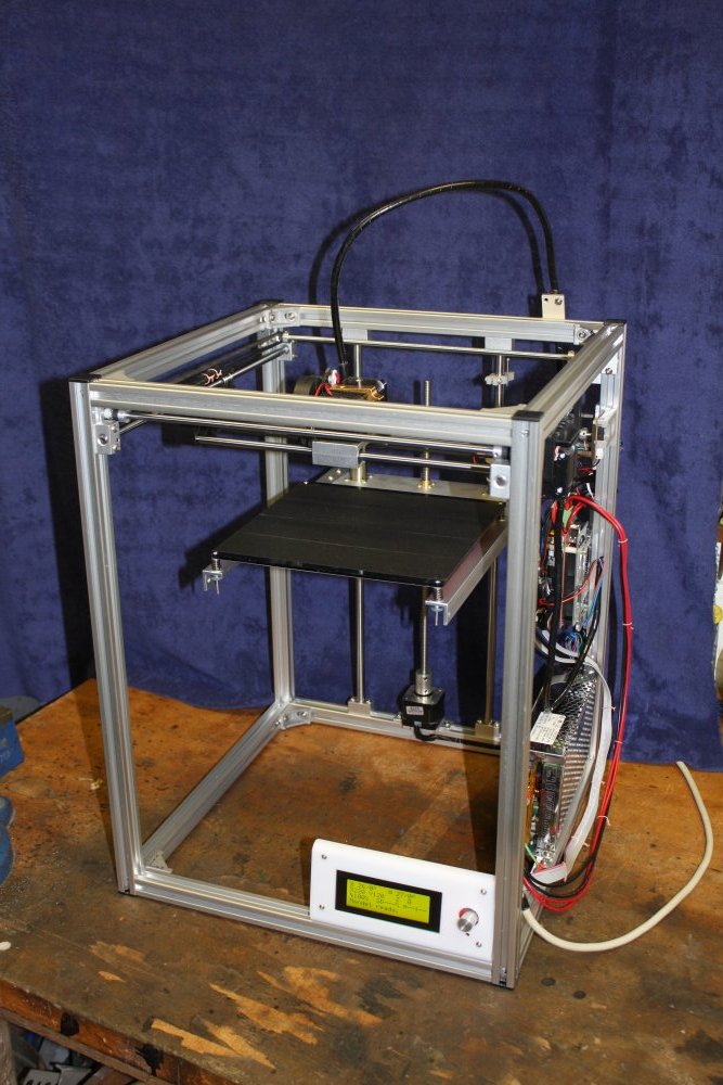
In October I had some extra money to spend, and in browsing 3D printer ads on Aliexpress came across this one, the FlyingBear P902.
(It was US$311 then.)
Apart from the price (which is quite a lot cheaper than equivalent printers I could find), this one has several points I like:
Features I like
- The near-cubical frame, with the head having both X and Y travel. This is close to the general design of the larger one I want to build, which has to be that way for several reasons. (We'll come to that later.)
Most other cheap 3D printers use a print bed with motion in the Y axis. But my later large machine will have a stationary bed, like in CNC routers. The main reason being that the bed has to be large, rigid and massive, with workpiece mounting points. So the head has to have all the required axis of motion. - It uses standard '20-series' (20mm square) T-slot aluminium extrusion, with the various mounting systems. Good, because I haven't previously used T-slot extrusions but want to try it, to evaluate for other projects. These sections haven't been readily available in Australia till recently, so far as I know. Certainly the usual major aluminium suppliers never carried it, and still don't. Typical.
- It's a kit, so I get to assemble it myself. This means I learn the traps of this class of X-Y-Z system alignment, calibration, toothed-belt feeds, etc. And cabling measures, which are obviously a major bugbear in CNC machines.
- The controller is a standard Arduino Mega 2560, with a "Ramps 1.4" rider board for power switching and stepper control. Full schematics for both are available.
- The printer firmware is Mendel, for which there's a lot of online information.
- The printer firmware source code is available. Very important point, since this is likely to save a lot of time with the larger custom machine later.
- Lots of other people all over the world are buying this one, so I'm not imagining the price advantage.
- The listing promises "Free shipping to Australia, via UPS Expedited." Most Aliexpress items are free shipping, and it works. The main downside is slowness, often taking up to a month from posting to arriving. But for free, one can't complain. Another risk factor is that mostly there's no tracking once the parcel is out of China. Some forms such as 'ePacket' do have excellent tracking and reporting; typically with ePackets I'll receive an email notification the package has been delivered, before I even get around to checking my letterbox and find the package.
For this purchase it's relevant that of the many things I've bought via Aliexpress, only one ever went missing in the post. But that was worth US$50, and I'd given up on it and written off the money just before ordering this printer. No refund since I had bought from that seller before, I trust them, not their fault the parcel got lost or stolen, and also the Aliexpress dispute deadline had passed.
So that "via UPS Expedited" was a strong attraction. It meant two things: quick delivery (a few days) and most importantly, online parcel tracking that actually works. No way the over $300 printer can 'just vanish' like the $50 worth of special wire.
Not so great
Having only a single extruder head. So no multicoloured prints, and more importantly no water-soluble support material for better, easier print cleanup. But again, this is supposed to be a basic learning tool printer, and single head will do for now.The side-mounted filament spool. Hmm... It's hard to believe that works well. Oh well, I can easily add an overhead spool holder.
Neither of these are really issues.
Plonk
So I ordered one.
There was a slight glitch with delivery. I'd ordered on 30th Oct. It was listed as shipped on 5th Nov, but the UPS tracking number given wasn't valid. I'm not sure if the seller was snowed under with all the orders and couldn't post by the Aliexpress deadline, or if (as they say) it took a while for the package to reach their nearest branch of UPS due to the Chinese "11/11" shopping peak. Or maybe they were just batching up a truckload of boxes for transport? Anyway there was a worrying interval without an actual UPS tracking number, combined with some communication confusion. This was starting to freak me out a bit.
Then on 10th Nov a correct UPS tracking number was supplied, and tracking worked.
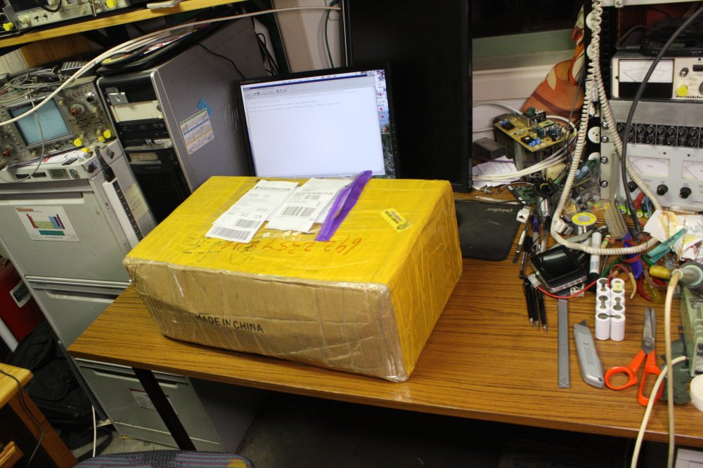
It arrived Monday 14th Nov. Really just four days (over a weekend) from when UPS received it, till the parcel arrived at my door. Pretty good!
 |
 |
 |
 |
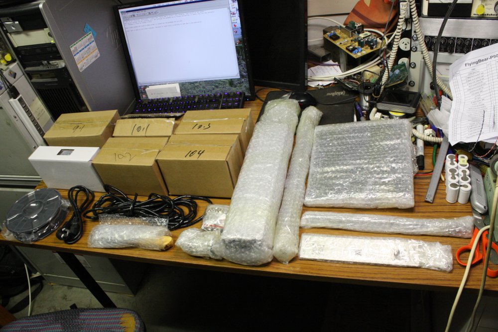 |
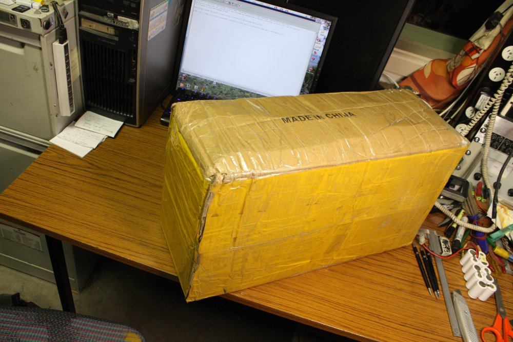
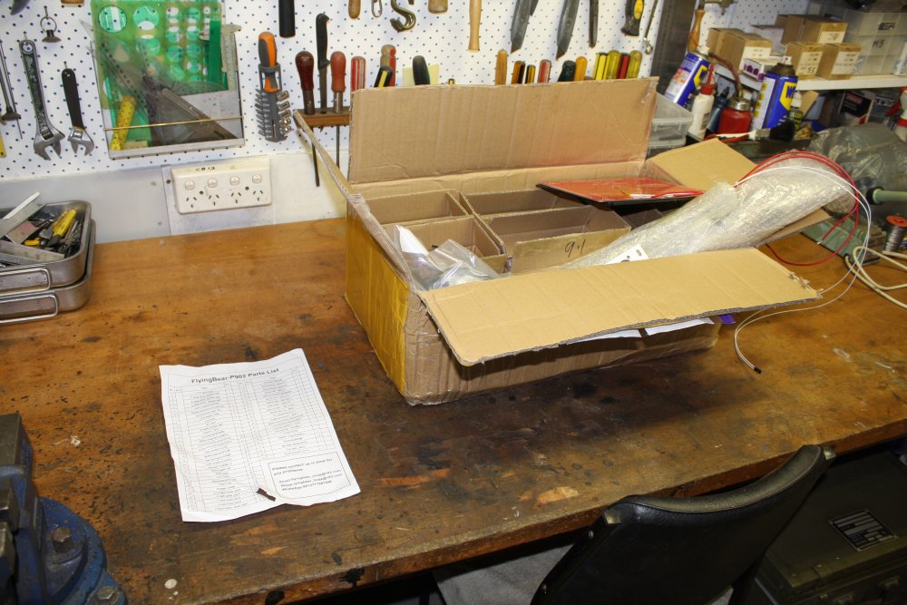
I didn't get a chance to even open the box till late that night. Exciting! But after midnight isn't a good time to try assembling anything, so I quit for the night. The box had been slightly squashed in transport, but no serious damage.
Apart from, ironically, the packing list, which had been ripped.
 |
 |
 |
 |
 |
 |
 |
 |
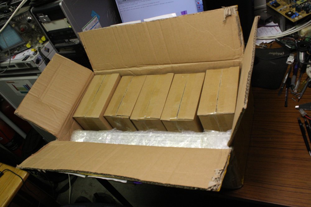
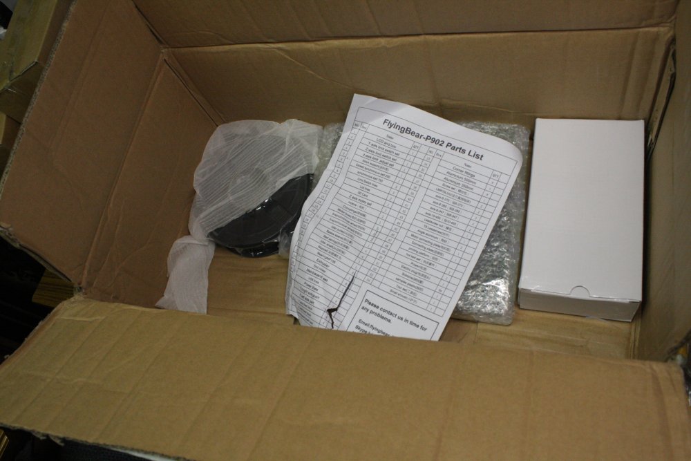
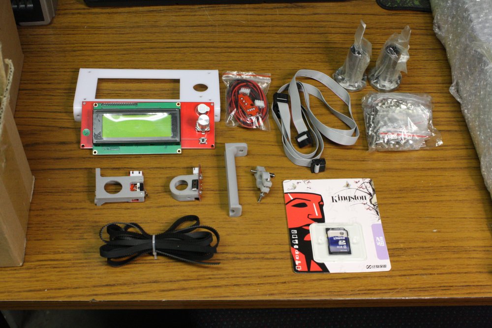
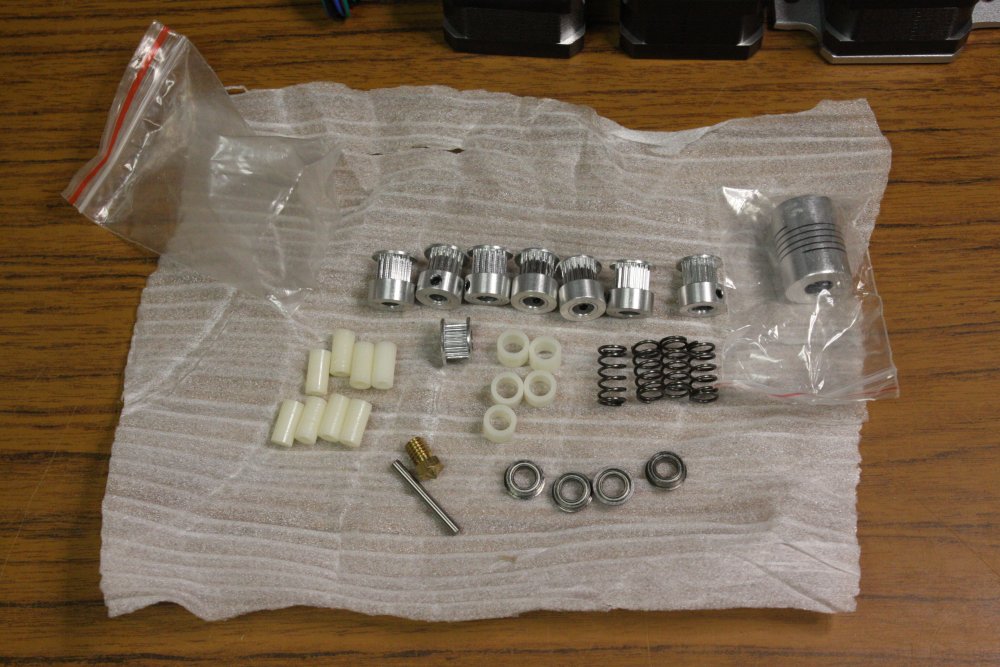
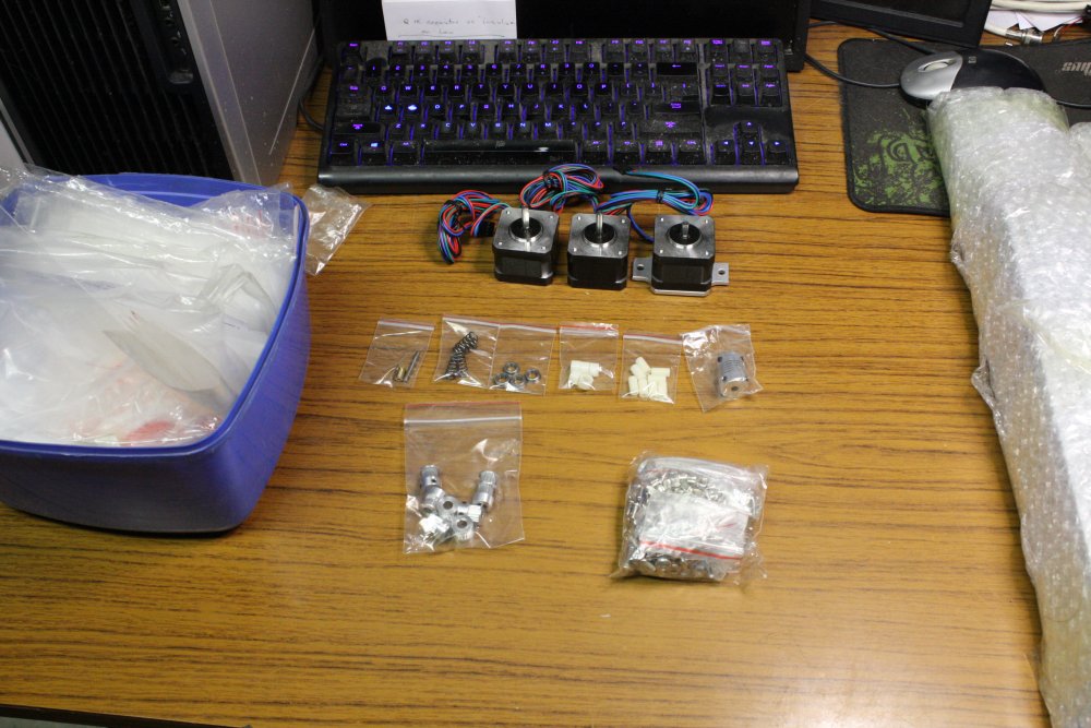
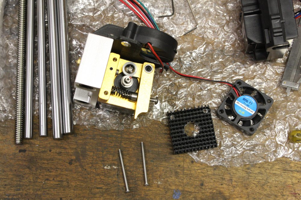
More unpacking the next day. Lots and lots of bits, as you'd expect. Slightly unexpected, is the absense of any printed assembly instructions. But this is due to those being all in video and pdf form, included in the download link you get when buying. I approve! Less waste paper. And the videos are very clear.
 |
 |
 |
 |
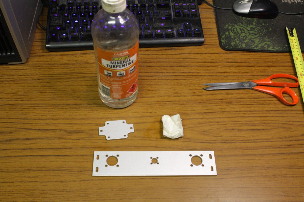 |
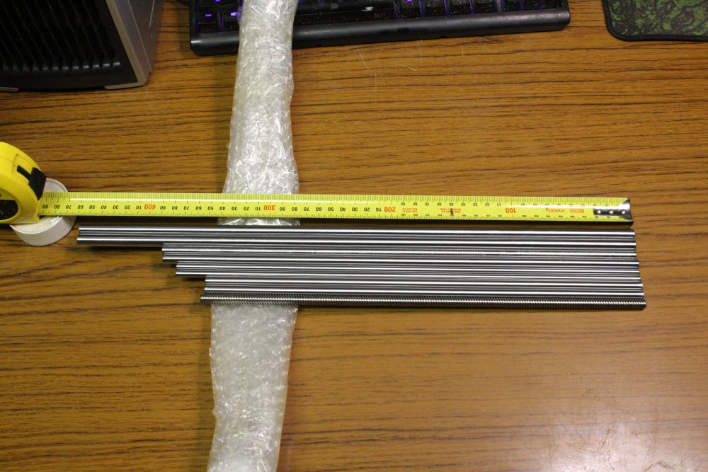
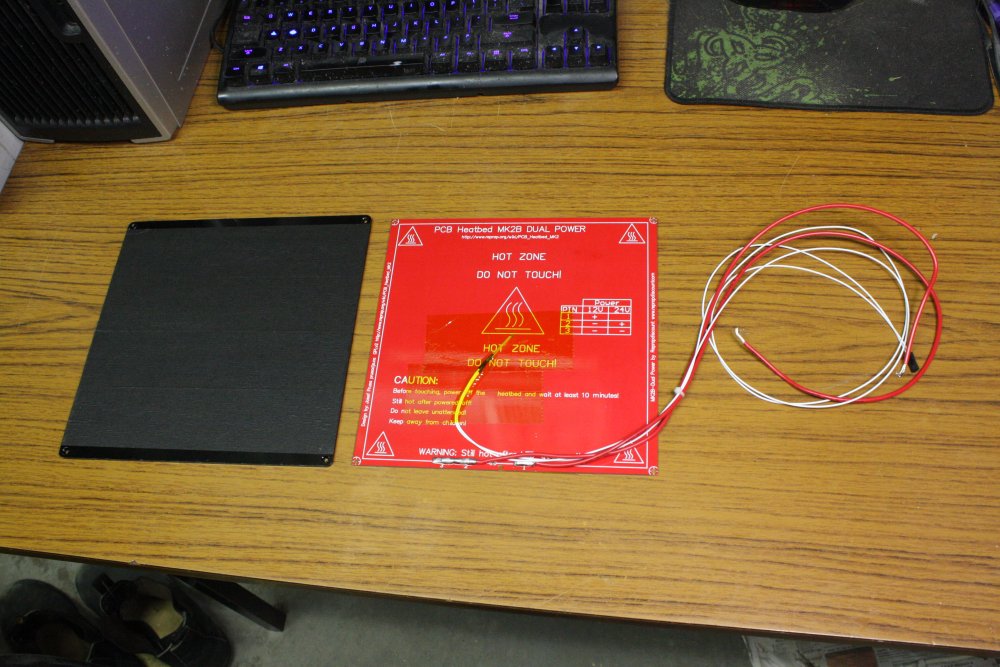
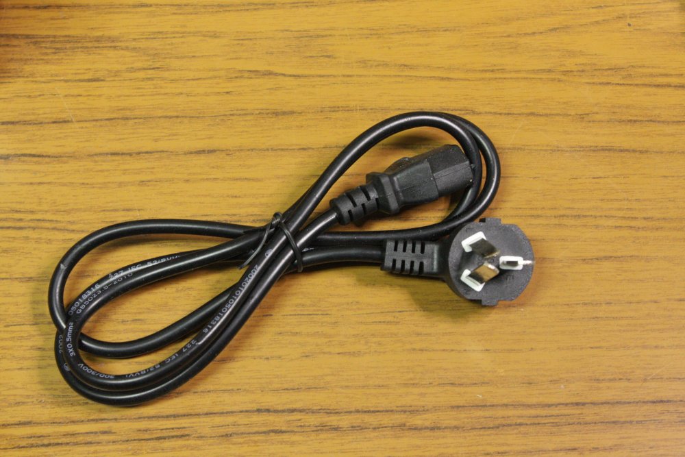
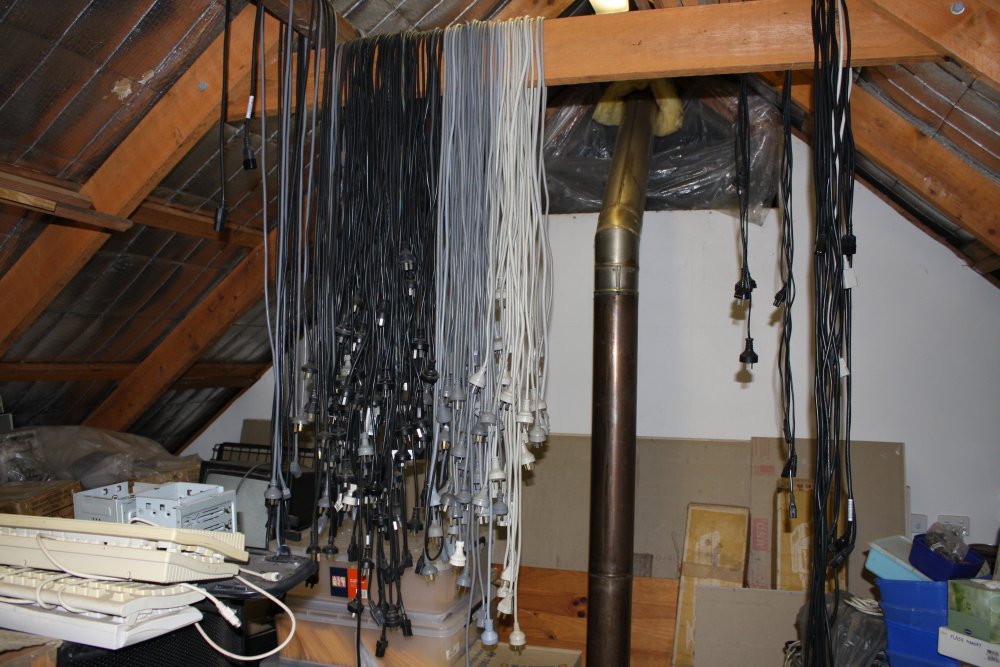
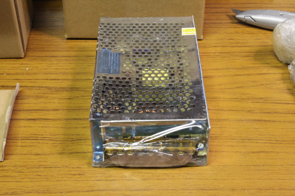
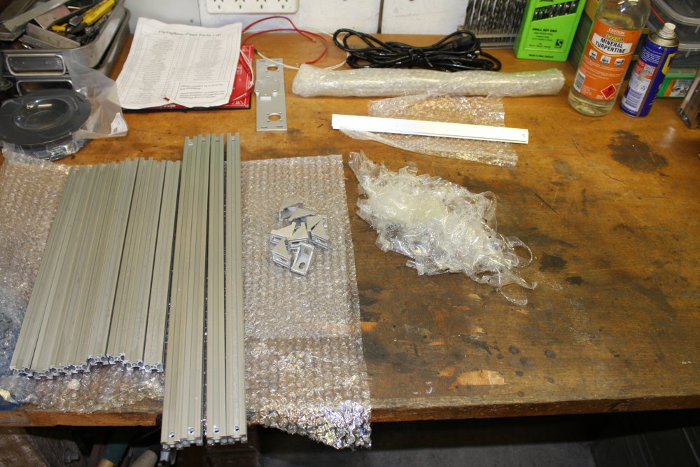
Minor repairs to shipping dents. The mains cord bent pins I didn't bother with since I have a few spare leads up in the storage loft (pic 2) and prefered to use a longer one anyway. The power supply slightly bent case was easy. Compared to an almost identical one of these I bought a while ago (from a different Aliexpress seller), that was shipped in a single, close-fitting light cardboard box and got seriously bent.
Some of the metal printer chassis parts had been packing-taped together, which left sticky gum on the metal when untaped. That came off easily with turps.
Overall I was really pleased — it's a complex kit, and nothing appeared damaged or lost.
 |
 |
 |
 |
 |
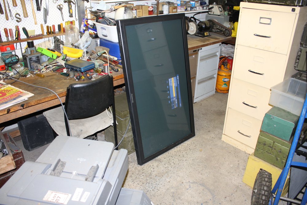
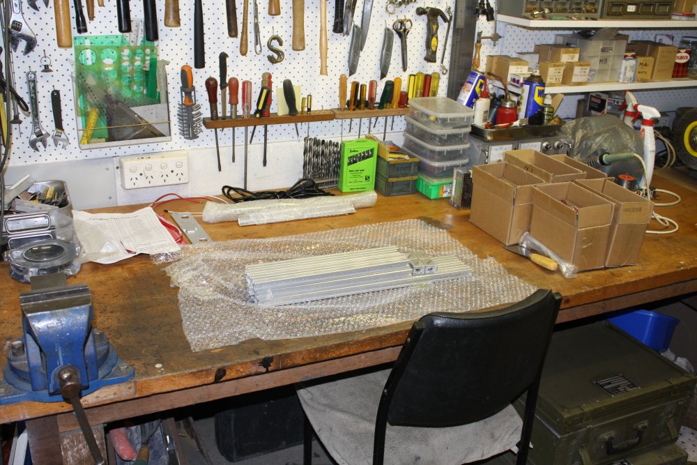
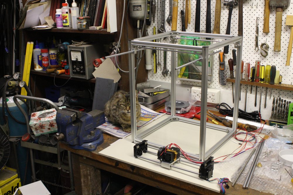
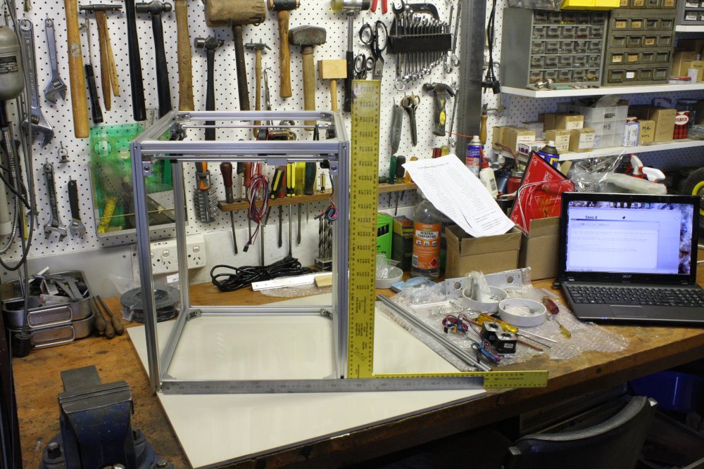
My only problem was that my workbench (not the desk in the previous photos) was currently a piled-up mess of stuff. Pic 1 is an indication, from earlier in November. It had grown worse since.
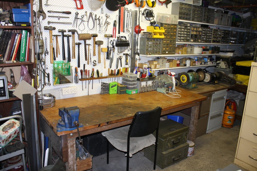
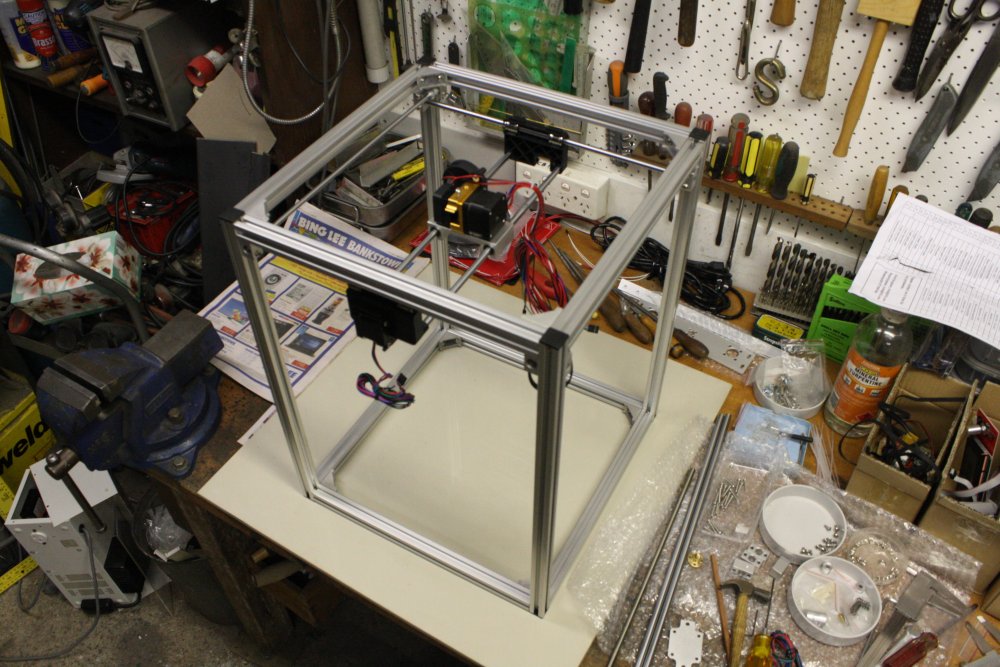
2, 3: After the cleanup, starting on the printer.
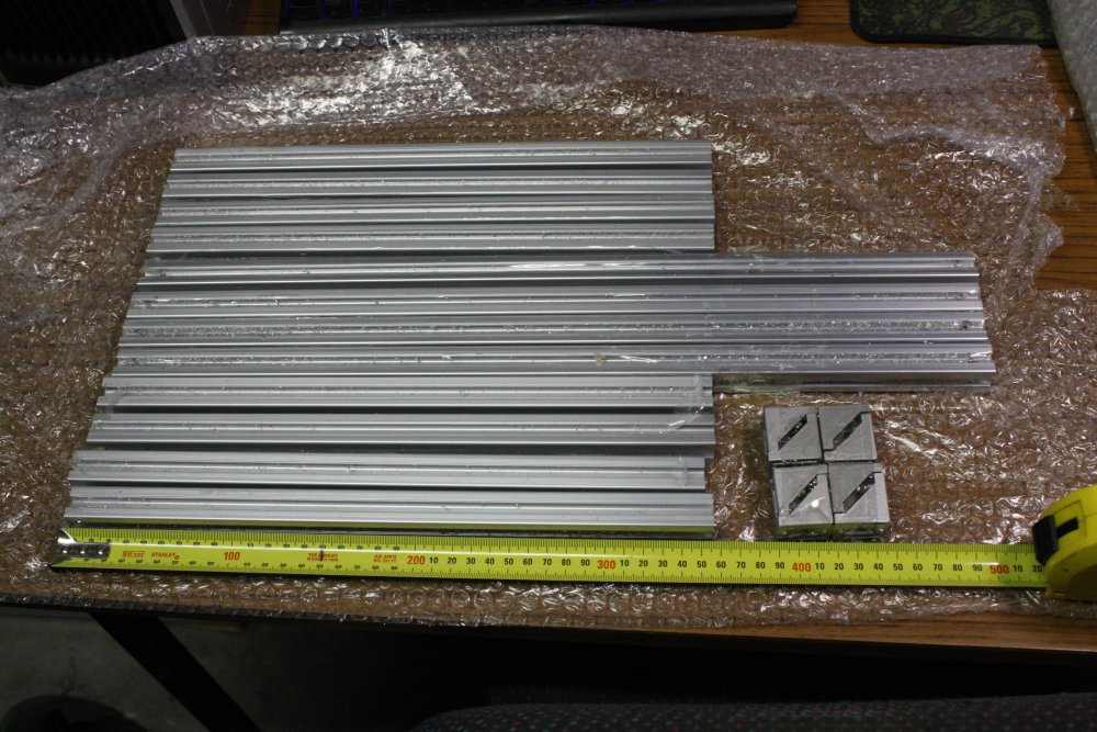
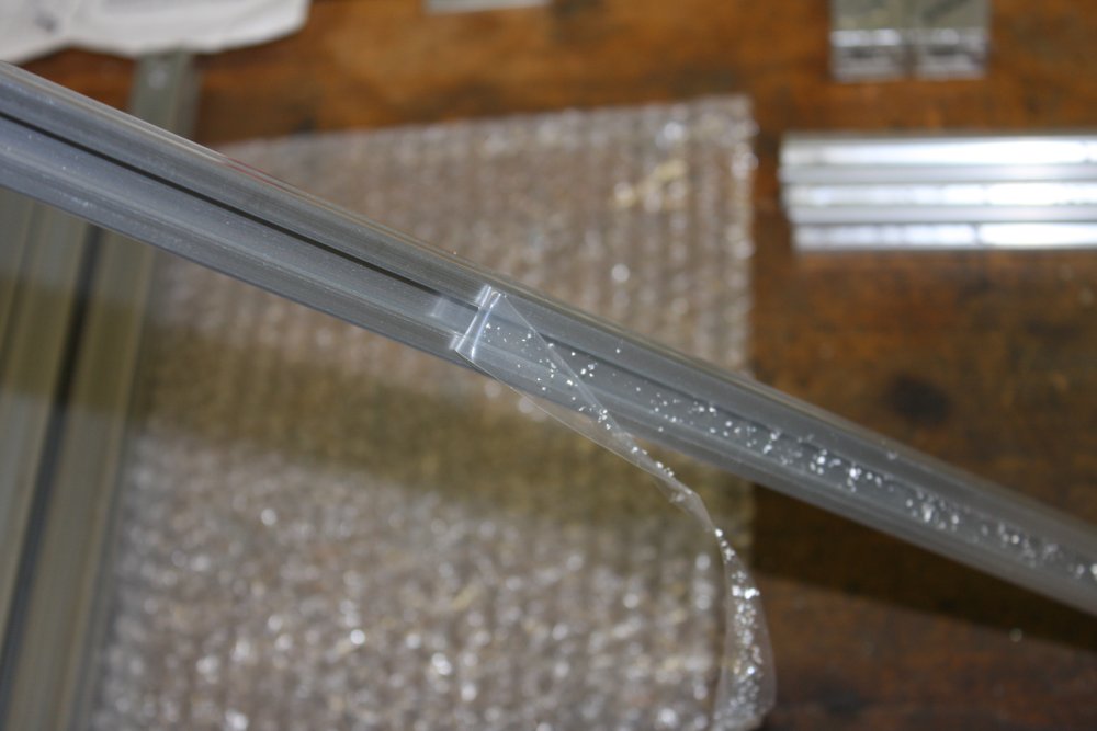
4, 5: First thing, remove all the cutting swarf from the printer frame struts. It's not just these protective strips, the central holes through the T-slot sections are also full of drill shavings. Pushed these out with a thin rod, then compressed air. Brushed the outer surfaces clean.
 |
 |
 |
 |
 |
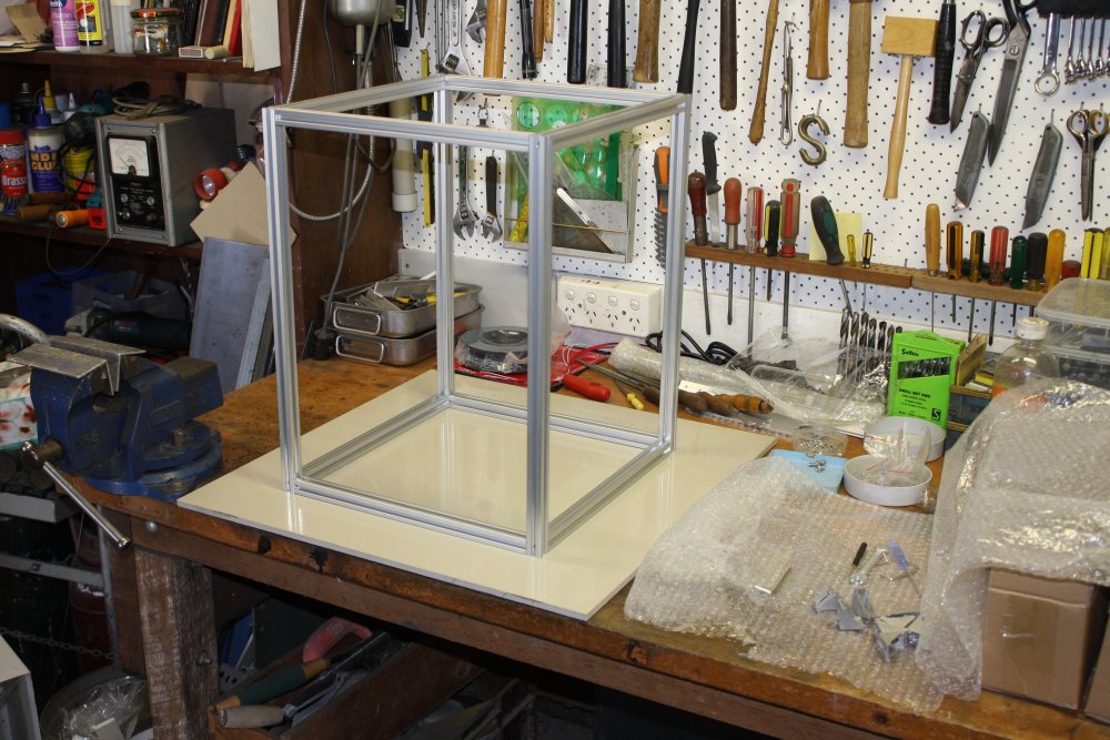
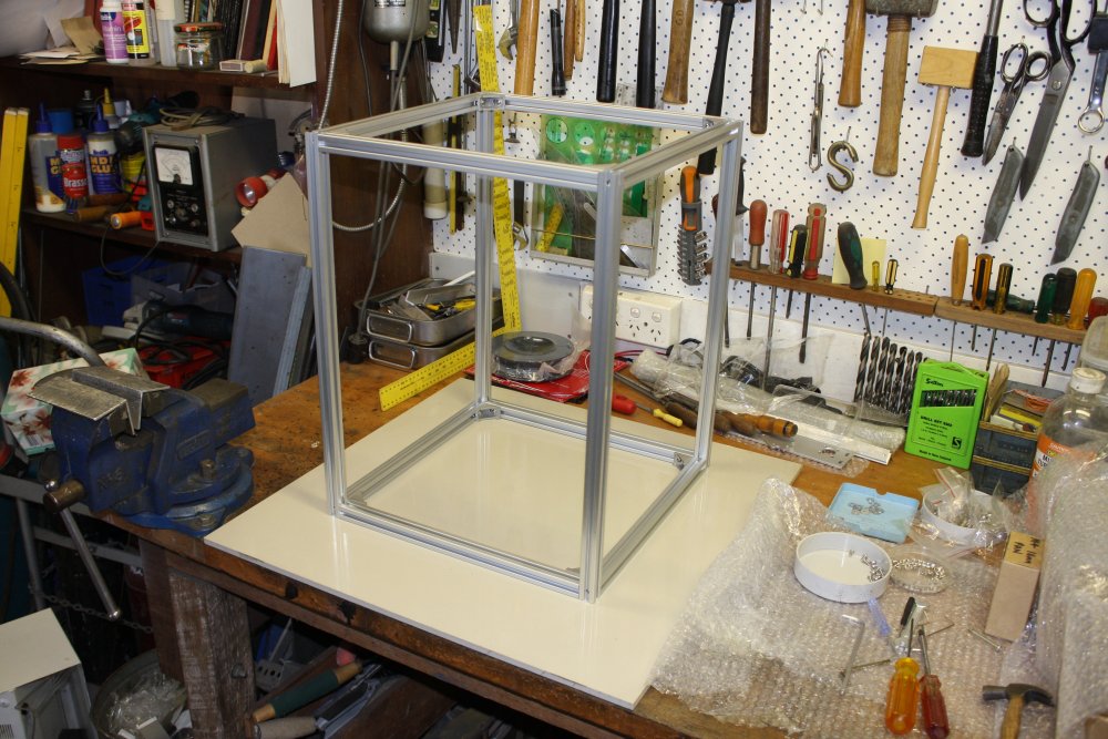
1: All clean. I then started assembling the frame, but realised a not-very flat benchtop wasn't an ideal surface for that.
2: A while ago I'd bought a pack of 600mm square thick ceramic floor tiles, for a soldering table surface. They are extremely flat, rigid and tough. Placing a steel ruler edge against the surface shows no visible bow, and reflections in the mirror-smooth surface seem perfect. So I used one of those as a 'flat' for this assembly.
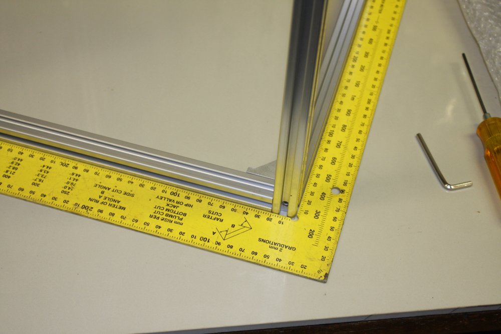
3: Something to watch is that play in the screw holes permits the struts to be tightened a little out of line with each other's surfaces. Hence the large square used to press the pieces into position while tightenting screws.
4: All the corner braces in. The supplied M4 x 8mm stainless steel button head screws, and T-slot drop-in nuts are nice, and in other parts of the machine 10mm screws would be too long. But I decided the 8mm ones, with these brackets and the necessary washer, were a little too short for my liking. Not many turns of engaged thread in the nuts. They're OK, but I like to see a nut with screw all the way through. So went and bought 300 10mm long ones and swapped out all the 8mm screws on the brackets. Also 100 of the M6 button head screws used for the strut end joins, but 16mm long rather than the supplied 12mm. I didn't swap those out, just starting to build up a stock of parts needed for using T-slot extrusions in my own projects.
Those were from Premier Fasteners, 3 Ladbroke St, Milperra 2214 (very near my place in Sydney) ph: 9772 1888, but there's also
The Stainless Shop. 170 Taren Point Road Taren Point. NSW 2229 ph: (02) 9525 1777
https://www.thestainlessshop.com.au
 |
 |
 |
 |
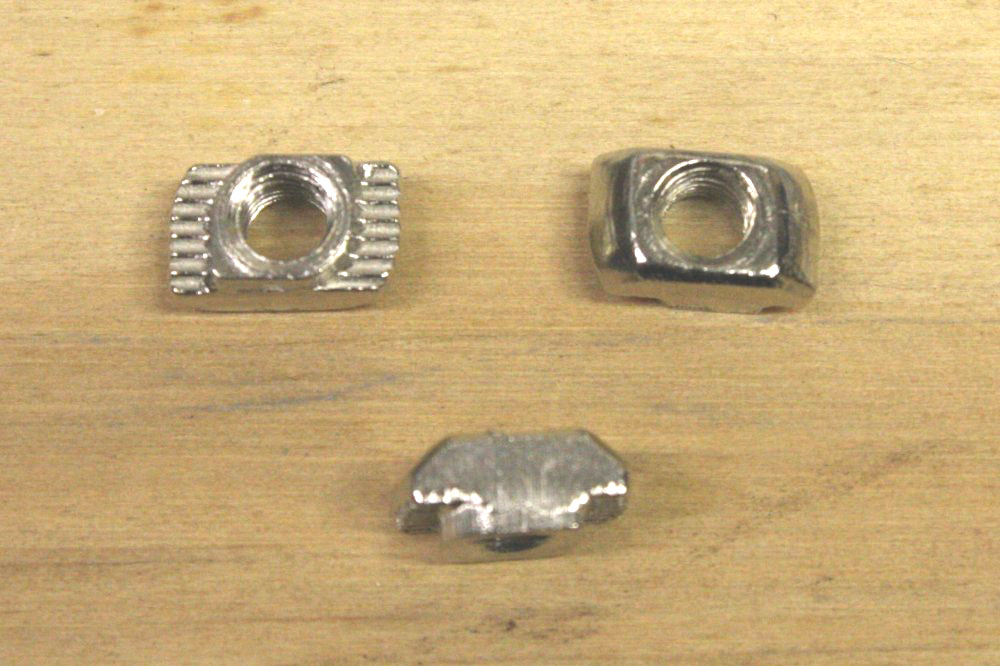
1. The T-slot nuts come in various kinds. So far I haven't found a cheap bulk local suppplier, but Aliexpress and ebay have plenty. There are the 'drop-in' kind (also called 'hammer head'), and the 'slide-in' (from the end) kind. To fit each of the extrusion sizes (20, 30 and 40mm, called 20-series, 30-series and 40-series, plus a range of screw thread sizes for each sort. The ones for this printer are drop-in, 20-series, M4. I have 200 pcs of the nuts, and 50 of the corner brackets on the way from Aliexpress for US$22. Seller XinYu Hardware.
These kind are neat. They (theoretically) rotate under the slot lips as you turn the screw before there's any tension. But you really have to visually check each one, that it did rotate fully before tightening. Worst case they get lined up by the slot and don't anchor at all. Where there are two anchors holding something down, you may think both are OK but it's just one doing all the work. Visually check.
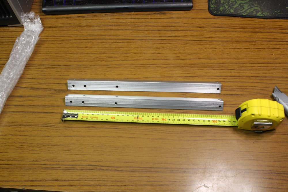
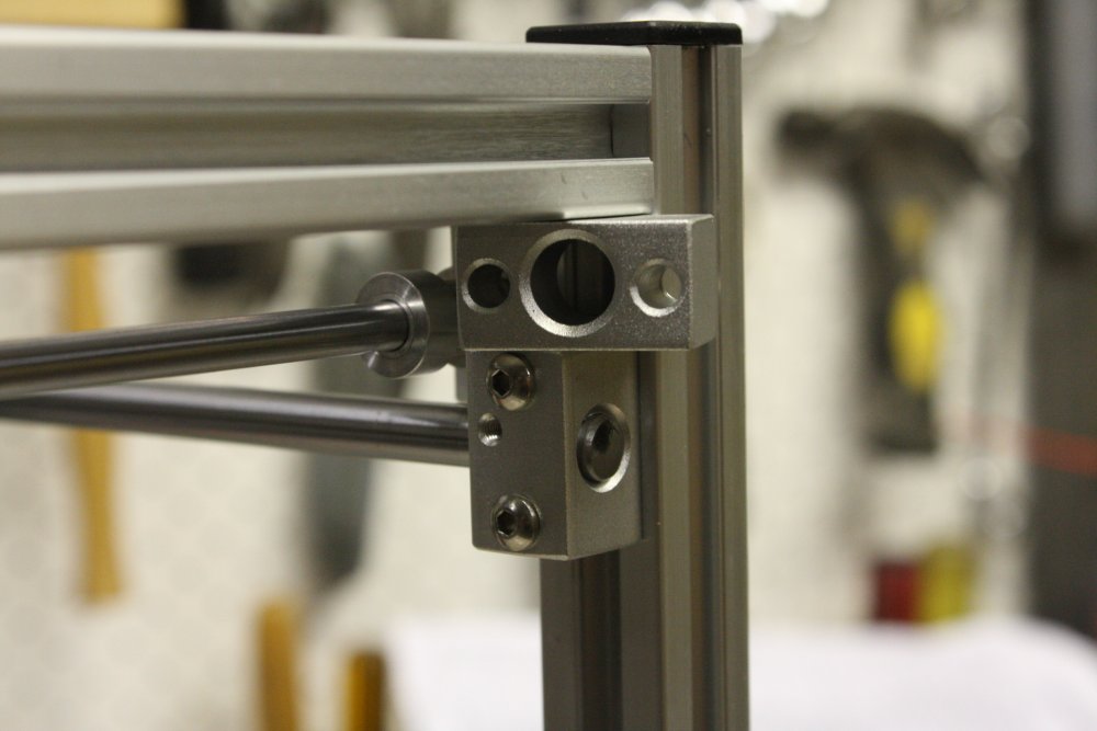
2. With the lower slide bar mounts, the instructions specify 15mm gap from the upper frame. They don't mention that all these mount blocks are 15mm square, so ones you haven't mounted yet make perfect spacers while setting the block and tightening the screws.
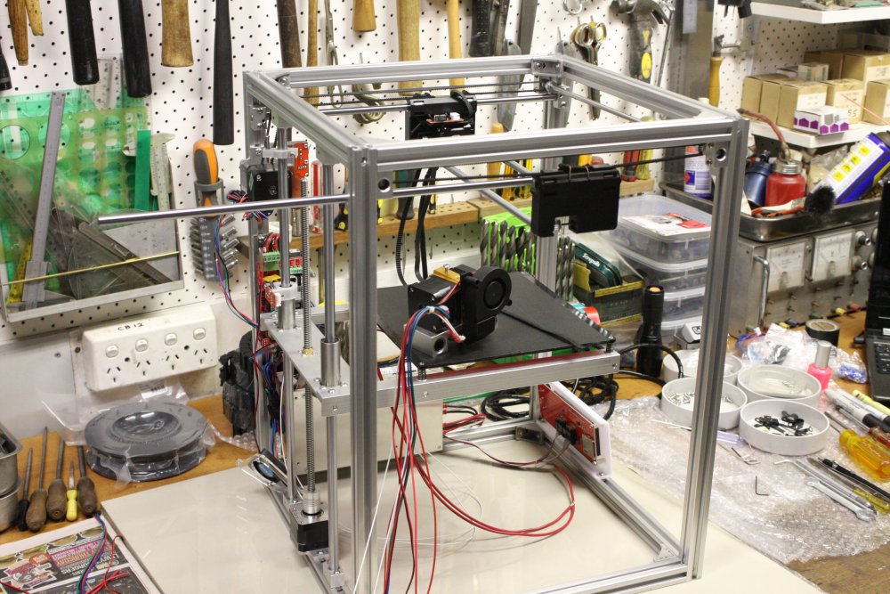
3. Ready to mount the carriage assembly. I was wondering what the mount point for the wires coming off the head was going to be. Ha ha.
4. Not wondering hard enough. Here it is mounted, which proved to be premature. But then I got sidetracked...
 |
 |
 |
 |
 |
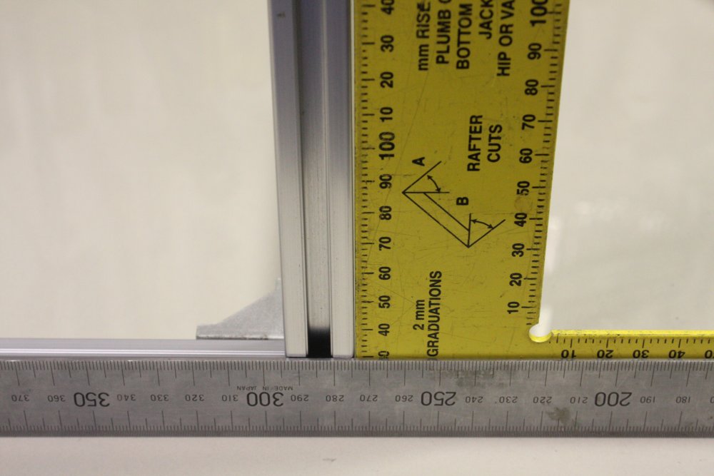
1, 2, 3. At this point I'd made sure during assembly of the frame that the top and bottom squares were actually square. But I hadn't thought to check if the uprights were square too. When I did... they are not. Some are up to 2mm out. Worse, it's not consistent among the verticals. Hmm... There are no corner braces for the verticals.
I spent a while struggling to work out why this is, and how to fix it. Both because I'd rather it was straight, and also because I was thinking (incorrectly) that this skew would affect the prints.
Also, I found that the various sections of the frame (which come in two lengths) are not quite all the same sizes. The short ones (horizontals) have nearly 1mm length variation. I swapped a couple round to get the front face top and bottom edges identical, but it made not much difference to the slightly trapezoid tilt of this face. This was a bit disturbing, but was it worth disassembling the whole thing and shaving them all to an accurate length? (I have a drop saw, so that was feasible.)
And I tell you what, if you are loosening off a section of the frame, then flipping the frame around, it's very easy to lose track of which particular edge's screws you had loosened. I got into the habit of sticking a bit of red electrical tape on the edge (or corner) I was working on.
After a while I realised that no, these frame-skew errors wouldn't affect the print accuracy at all. The only things affecting print geometry are the rear rods the bed rides on (these have to be parallel and 90 degrees to the plane of head movement), and that the X and Y rails are actually at 90 degrees to each other. Also of course, that the frame is rigid and doesn't drift.
Eventually I concluded the overall frame skew was probably the result of very slightly non-square cuts of the horizontal piece ends, plus the minor length variations. And that my drop saw cut would probably be out of square by a similar amount, so there wasn't much point shaving ends. What the frame really needs is a few large square brackets or braces on the upright's corners, to force it true. I ordered 50 of the standard brackets as stock, but probably won't bother adding some to this frame.
There's no need to fix it, since it really doesn't matter.
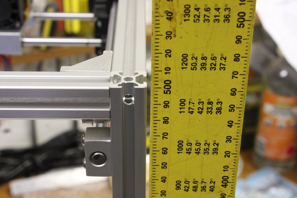
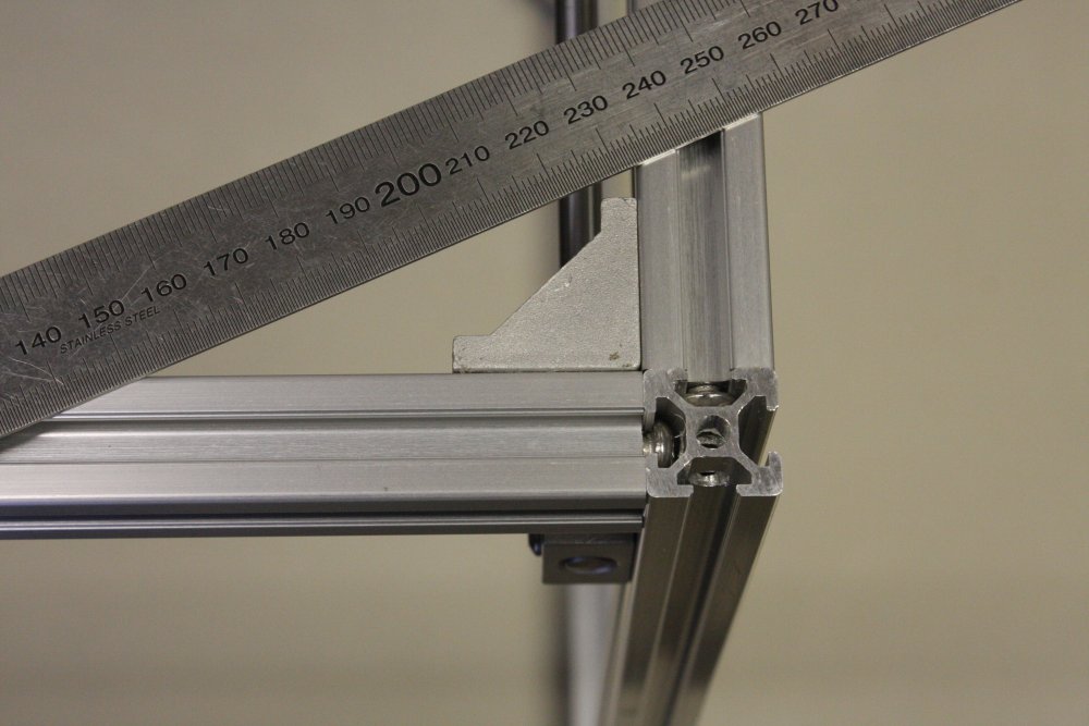
4. Just a pic of the corner construction.
5. Having decided to live with the slight frame skew, on with the rest of it. By now I'd realised there actually isn't any solid clamp point for the cables to the head. Meaning that after a lot of back and forth movement, the wires may eventually break where they enter the head components. What to do about that?
After trying hard to think of something that didn't involve modifying the head at all (and failing) the only thing I could come up with was a post screwed into the only bit of exposed thick metal of the carriage. Can't do that with the head assembled and in the machine, so out it comes.
 |
 |
 |
 |
 |
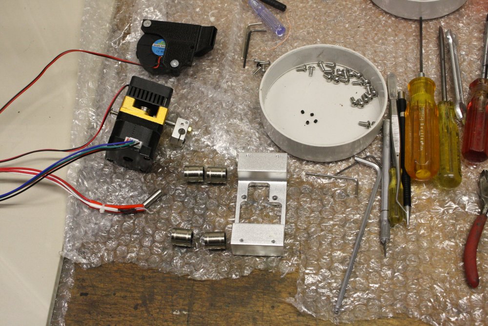
1. Disassembled down to the bare frame of the carriage.
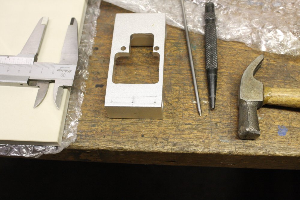
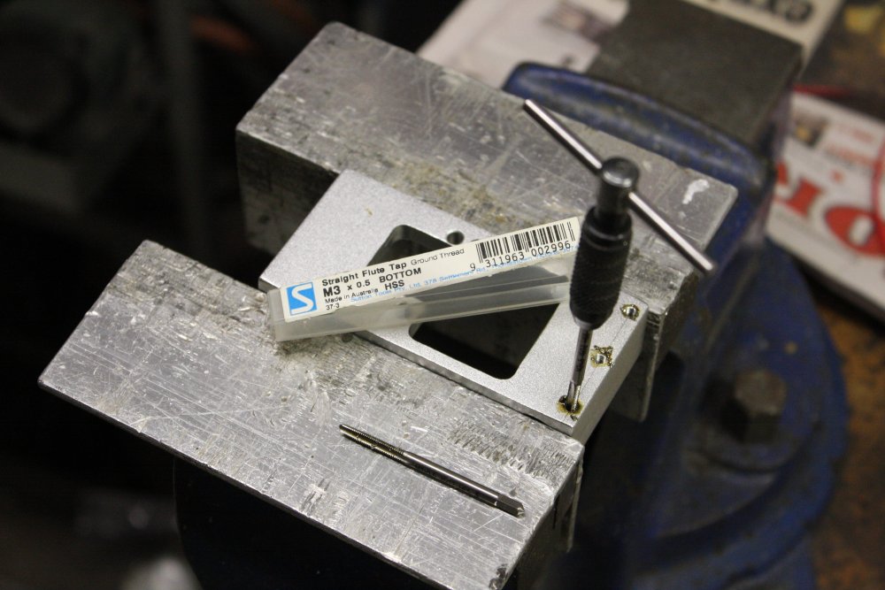
2. I only need one threaded hole in the carriage, but while I have it apart I'll do three. Extras for whatever I've forgotten atm. Here center punching for drilling.
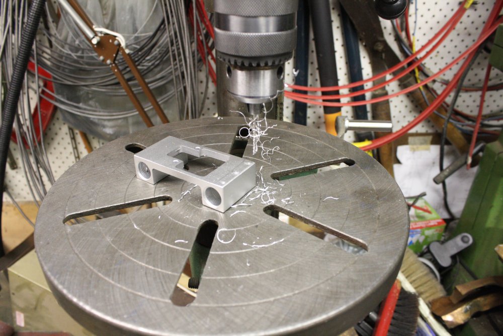
3. Drilling. M2.5. Stopped just short of breaking through to the linear bearing mount holes.
4. Tapping for M3 screw. Started with a taper tap, finished with a 'bottoming' tap, that cuts threads to very nearly the hole bottom.
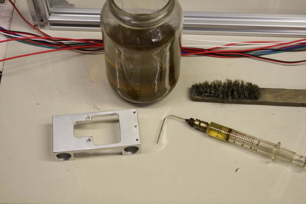
5. Clean out holes with a jet of kerosene. (It's old kerosene, the blue colour has faded.)
 |
 |
 |
 |
 |
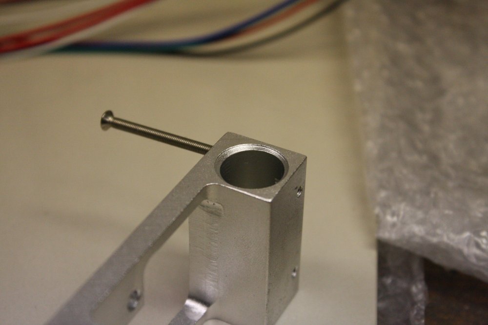
1. No breakthrough.
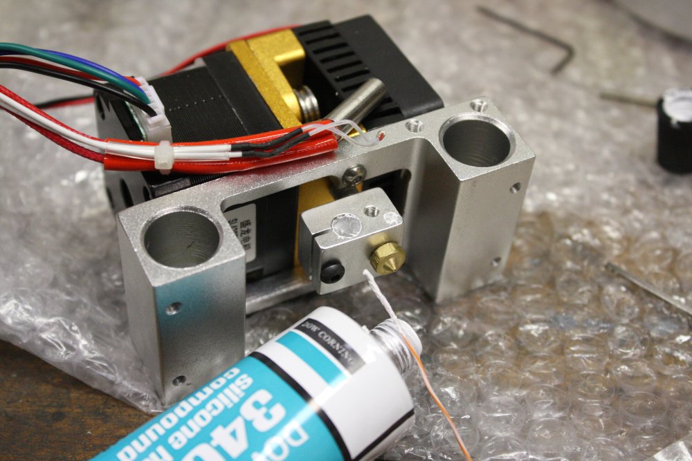
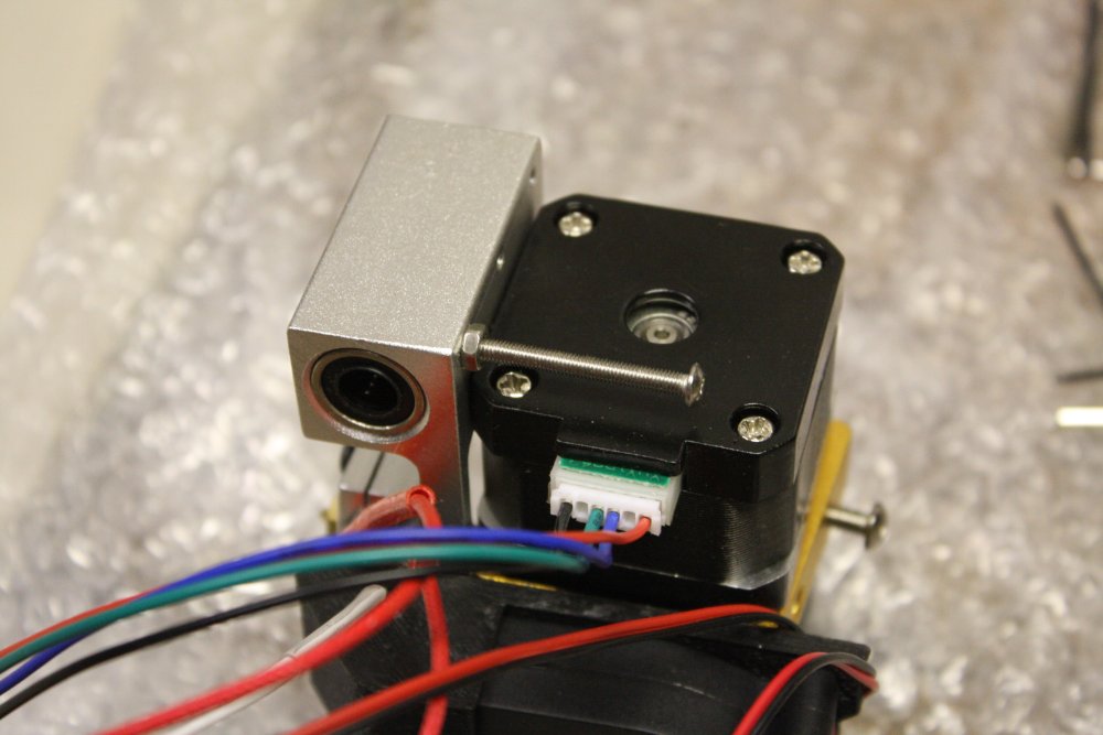
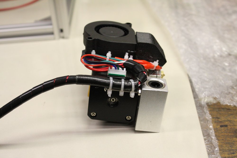
2. Re-mounting the extruder head heater, added some thermal conductive paste to both the heater resistor and the thermistor. May not be particularly helpful, but can't hurt.
3. The screw with a locknut, and preparing to dress the wires.
4. More dressing. Want to completely eliminate any varying strains on the connector, thermistor, heater, etc. Note small hole drilled in blower mount plate, for the left-most wiretie.
5. Winding the sleeve. Back in the 1970s this was called 'Spirwrap', and it still is. Can't imagine why. Anyway, keeping the loose bundle in a small plastic bag makes this tedious chore easier.
 |
 |
 |
 |
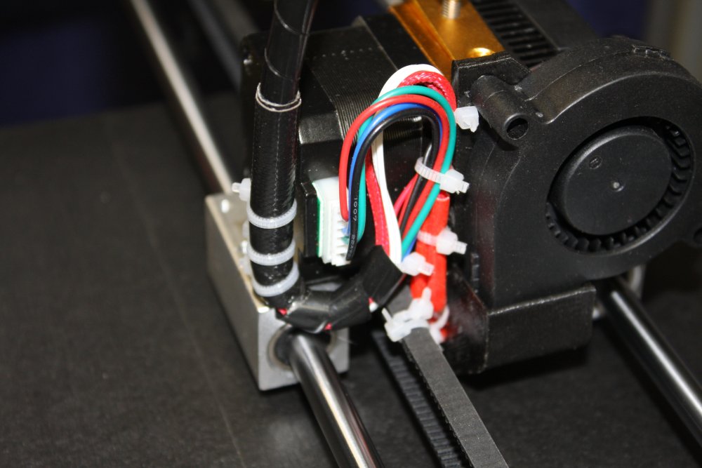
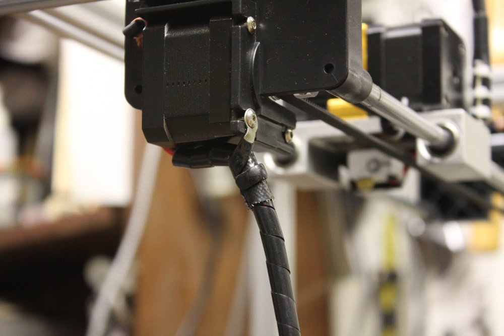
1. A couple of layers of gaffer tape stiffens the spirwrap where it's to be tied to the post.
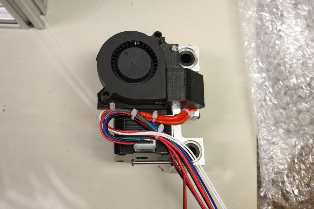
2, 3, 4. All done and mounted. Most of the wires had plenty of spare length, but it turned out the thermistor wires (white pair) were only just long enough after using up an extra few cm with this loop. If I was doing it again I'd run the white wires more directly here.
Note in pic 4 the excess toothed belt is not cut off, but folded back under the head frame and wiretied in place. I didn't want to cut the excess belt, since any time I have to disassemble and redo this stuff, the extra belt length is needed for holding onto to tension the belt. Same with the other two belts — just tie the excess length out of the way.
 |
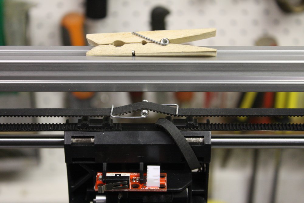 |
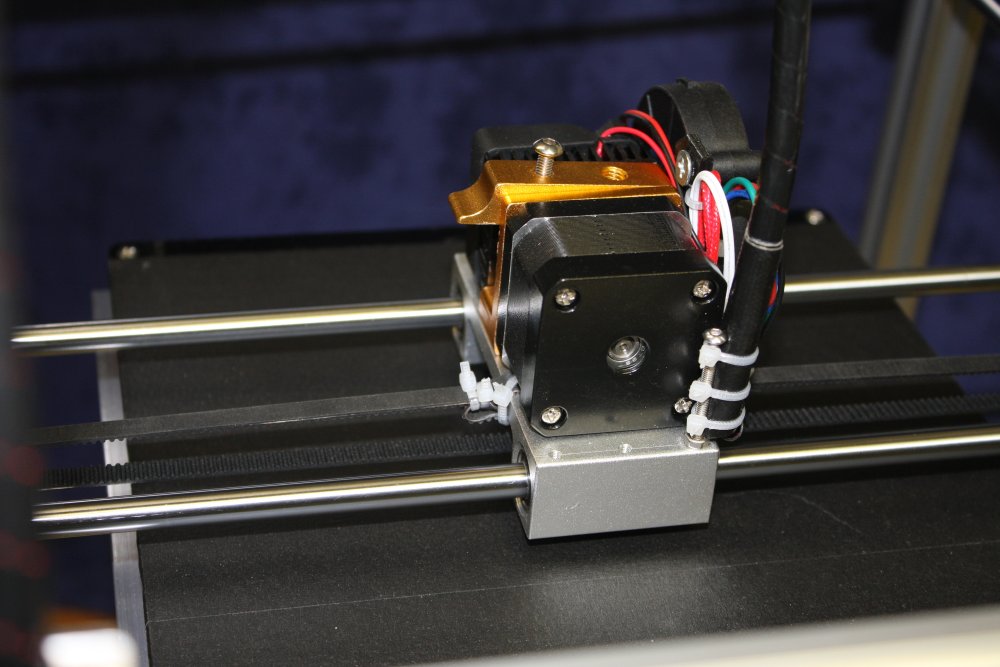
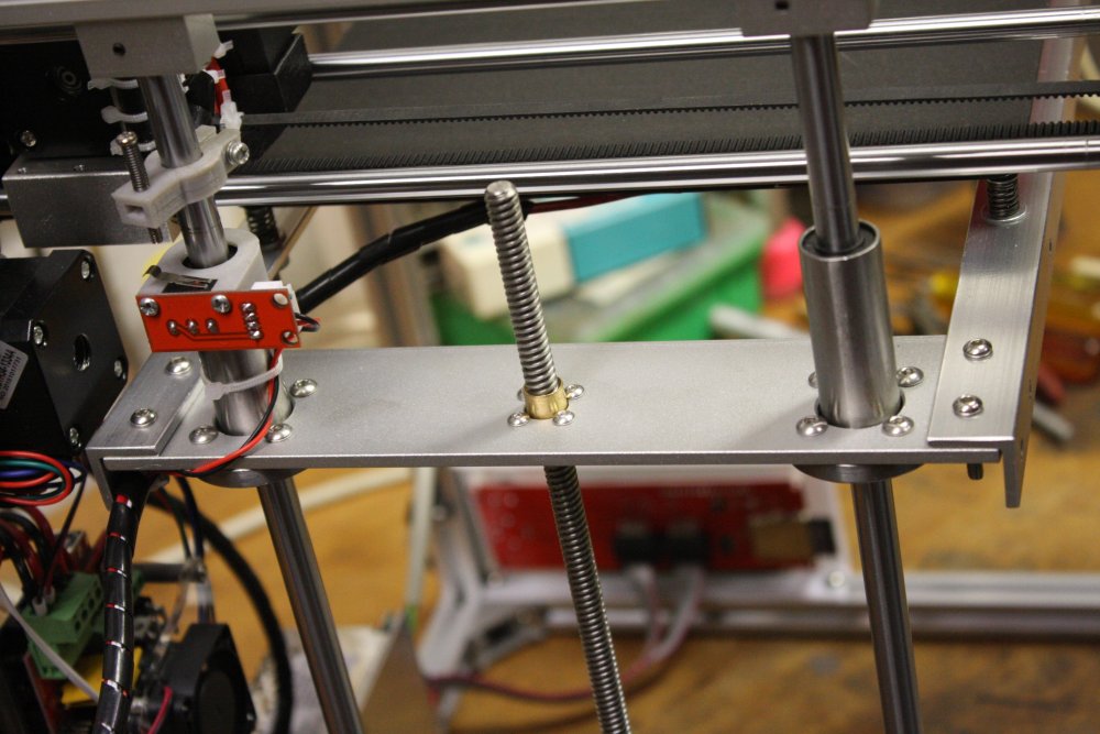
Tensioning the three main belts correctly is a bit problematic, as there's no adjustment other than by increments of the belt teeth. With all of them this means the increment is actually half a tooth spacing, since the belts are being wrapped back on themselves. But it's still too coarse. On mine I could have the two Y-axis belts either too loose (floppy) or too tight (moving the head by hand feels uneven.) To fix this I first tried some paper shims under the front shaft mount blocks, and that fixed the left hand belt. But the right hand one needed a lot of shim, so instead I loosened it by one tooth, then added a tensioner. See pic 2 - it's the spring from a clothes peg. Now both belts are about the same tension, and the head feels smooth to move by hand.
Darnit. I lost a series of photos somehow, of fixing the end-play in the vertical feed of the print bed. This was very obvious — with the bed at any position, pressing it down lightly by hand made it sink a couple of mm. It would spring back up, but how accurately would the position restore?
The play was due to two things. One was the spiral coupling on the lead screw, which also acts like a spring axially. The second was springy end-play of the Y-axis stepper motor shaft. To fix the stepper end-play, I removed the base mounting plate, found a small ball bearing in my parts boxes that exactly fitted the gap between the stepper internal shaft end and the mount plate. Machined a small nylon sleeve to keep the ball bearing centered in the stepper end hole. Put that all together and now there's no perceptible shaft end play on the stepper.
For the coupling, I found a steel bearing the same diameter as the lead screw. Dropped this into the interior of the coupling on the stepper, then the lead screw. Used shims to slightly stretch the coupling spiral, pushed the lead screw in till it hit the bearing, and tightened the grub screws. Removed the shims, and now the coupling is a spring trying to pull the lead screw down — onto the bearing.
End result, is no vertical play at all on the print bed. Other than in the lead screw to nut, but that stays set under gravity.
Other photos in that set, were of fitting spirwrapped wires in the T-slots. As-is, the spirwrap fits the slot loosely. But it can be made a tight fit where desired by adding a couple of layers of gaffer tape. This is useful, for instance where the cable from the X-axis motor and end-stop can be just clipped into the frame at their fixed end.
 |
 |
 |
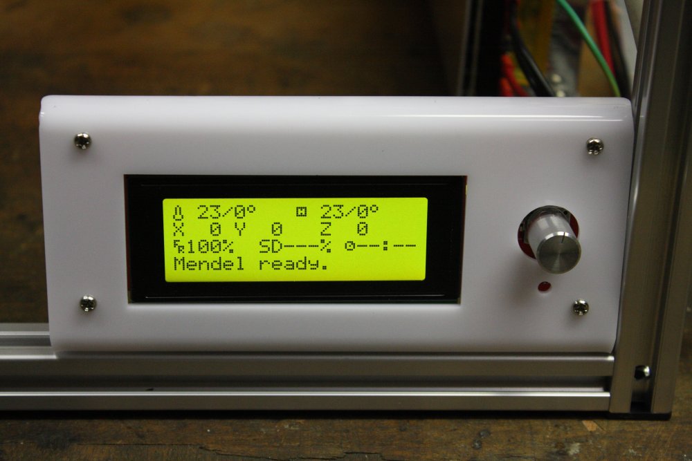 |
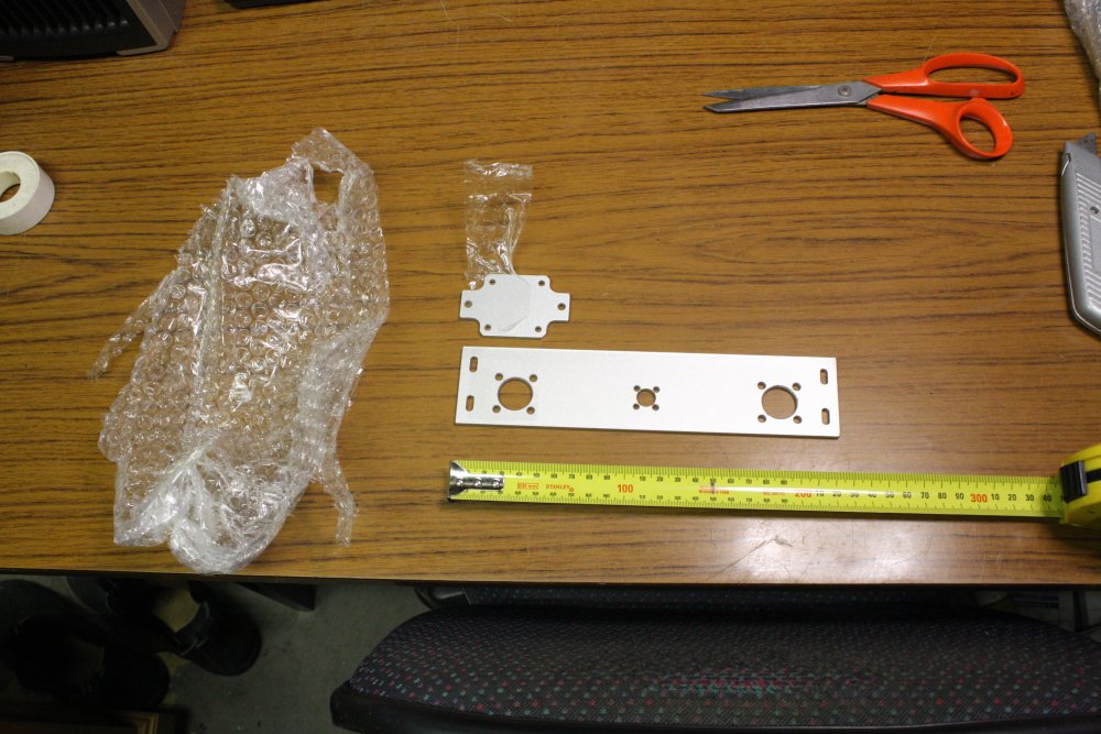
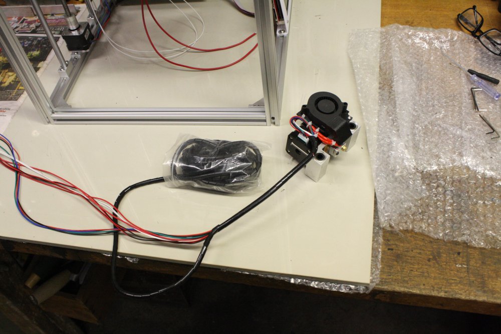
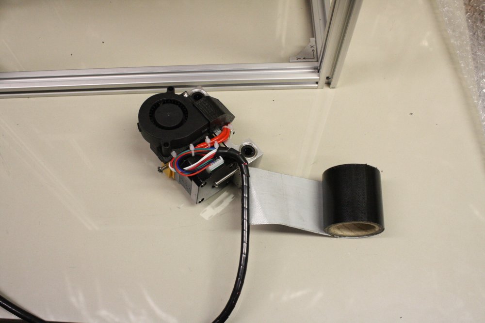
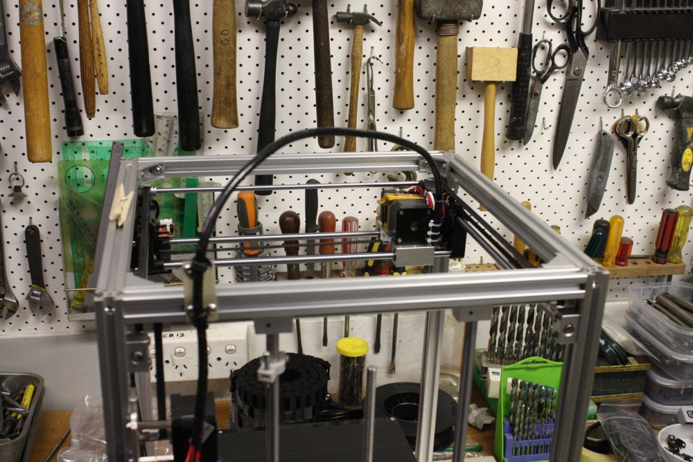
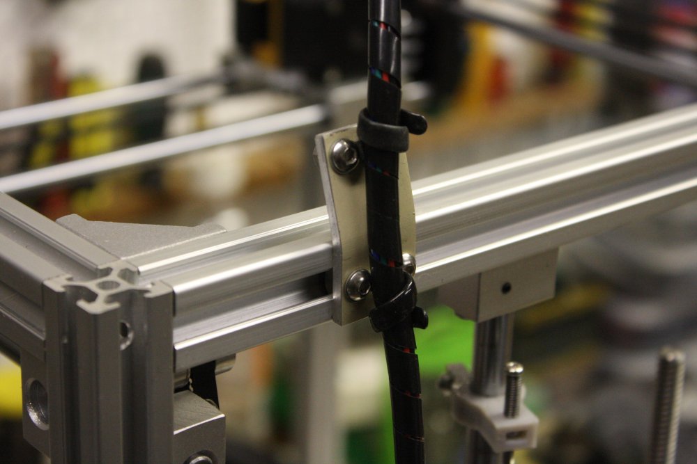
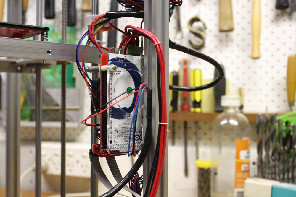
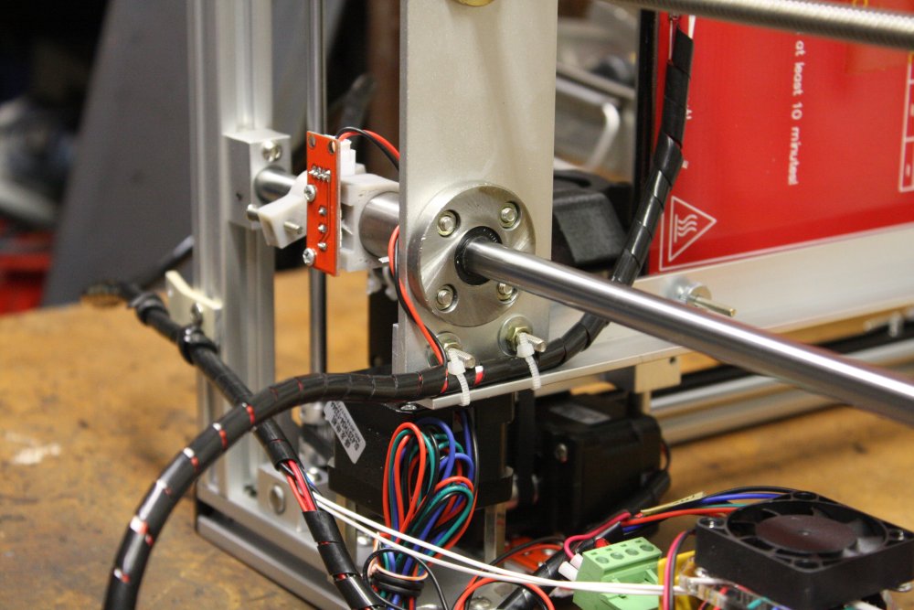
1, 2. A small mount plate for the extruder head cable at the rear frame.
3, 4. Powered up for the first time, it runs. Bed and extruder temps are correct at room temp, auto reset to origin works, and all axis can be manually set. Nice.
 |
 |
 |
 |
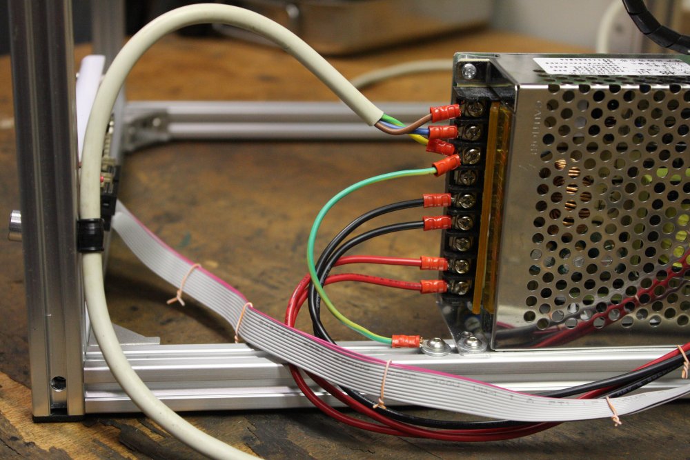
1. Later I'll add a mains switch and IEC socket on the frame here. For now, a solidly anchored mains cord, and properly earthed frame rather than rely on grounding via dubious internal connections in the power supply. Ringlugs because I can. (Yes, normally the protective cover is closed.)
2. X-axis cable securing point.
3. The other end of the X-axis cable. Tape wrapping it makes for a very solid clip-in to the channel.
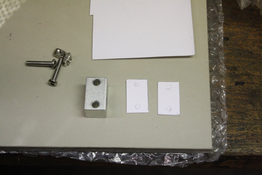
4. Bed mounting plate. In the instructions the screws on the linear bearings are other way up. But I did them this way because it looks neater. The trick is...
 |
 |
 |
 |
1. The trick is, that the nuts don't quite fit in the linear bearing underside recess holes, but they can be press fitted in by force. Put the flange on an anvil, and use a pin punch that covers the entire nut. Apply hammer not so gently. Oh, and these are not the M4 nuts supplied with the kit. Those ones are slightly bigger, and this might not work. Also those are quite a loose fit on M4 screws, so I didn't like them much.
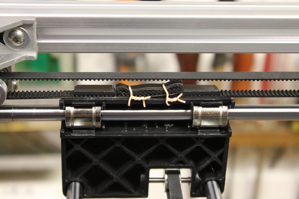
2. When you don't want to waste nylon wireties... You can often find junked lengths of cat-5 cable. The solid core kind (building wiring) is very useful. The outer sheath is loose, and can be pulled off meter lengths easily. The twisted pairs are easy to separate into individual wires; just grab one end and slide one wire along the other. Ends up with one wire straight, and the other one in a tight spiral, that can be pulled straight again. Result: infinite free 'wire ties' like these. That can be undone easily and reused too.
Also drilled a couple of small holes in the plastic carriage body, to allow tying down the excess toothed belt like this.
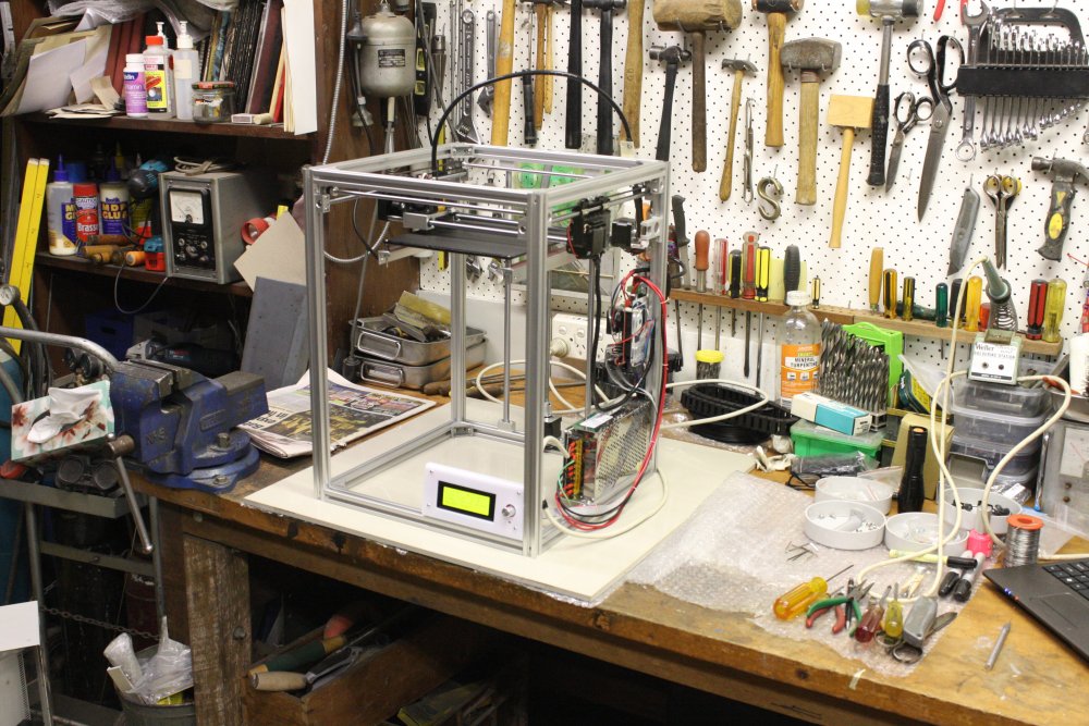
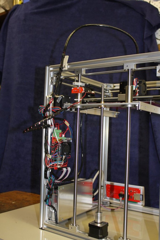
3, 4. A couple more pics.
Overall I'm quite pleased with it, given the price. No show-stopper problems, all the things I wanted to improve a bit were easy, and the design seems practical.
Now I just have to learn how to use it. That's where the learning curve comes in.
20161216 Murphy and the Observer Effect
A brand new 3D printer, and eagerness to try it out. Plans, what are they worth? By now I should know not to make plans. Anyway, other time demands arose. One of them a writing task of an ironically related topic. That I'll detail when it's complete.
There were other events too.
A friend of mine is a teacher, and happens to teach high schoolers 3D printing. Last weekend she finally had a Saturday afternoon free to come round and look at my printer. It was intended to be a 'lesson swap' - I teach her how to use a multimeter and soldering iron, and she'd run through some 3D CAD software for me.
The printer has been powering up and doing basic stuff perfectly well for the last two weeks, including late Friday evening. On Saturday with her watching I turned it on. Nothing. Nada. Dead. Ha ha ha...
That's one of the finest instances of Observer Effect I've ever experienced. Shrodinger's Inverse Cat — your cat is running around perfectly well and happy, until you try to show it to someone. When it's suddenly a cat corpse in a box.
 In the evening, after 'Miss Observer' was gone I fault checked. First check — the power supply. Its output is zero, not the desired +12V.
As I'd suspected immediately, and this is good since power supplies are easy to fix.
Also an 'early mortality' like this is likely to be something obvious.
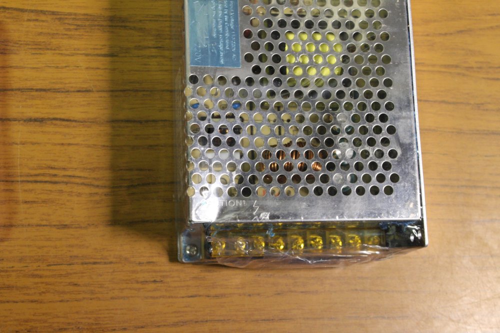
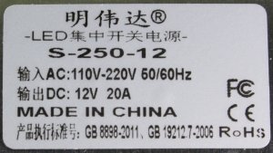
This is the maker's label.
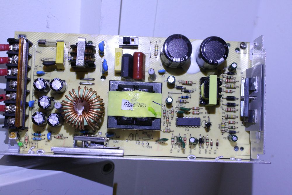
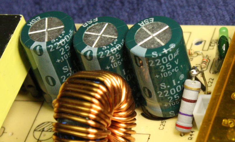
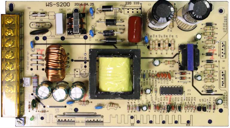 Here's the power supply PCB.
The main drive transistors, output rectifiers, and mains voltage selector switch are removed in these pics.
Doodlings in black marker pen on the solder side are mine.
For the search engines: FlyingBear 3D Printer power supply schematic.
Model: S-250-12 DC: 12V 20A.
PCB: WS-S200 2016.04.25
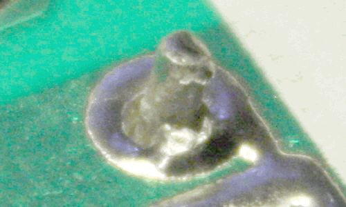
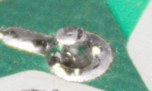
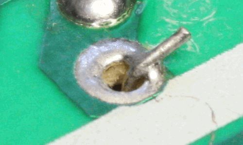
Some of the solder joins were terrible:
 |
 |
 |
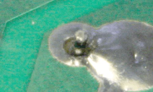 |
The one outlined in red is what killed the supply. It wasn't making any contact at all by then, but it must have been contacting originally. It's a pin of one of the two mains voltage DC storage caps. When whatever tiny contact there was failed, the resulting arc transients also took out one of the main switching transistors.
Of course that wasn't apparent till after I'd fixed the bad solder joints and the supply still didn't work. While identifying the dead transistor I'd started deriving simple sections of the schematic from the PCB. And while doing that, I noticed something much worse than the bad solder flow.
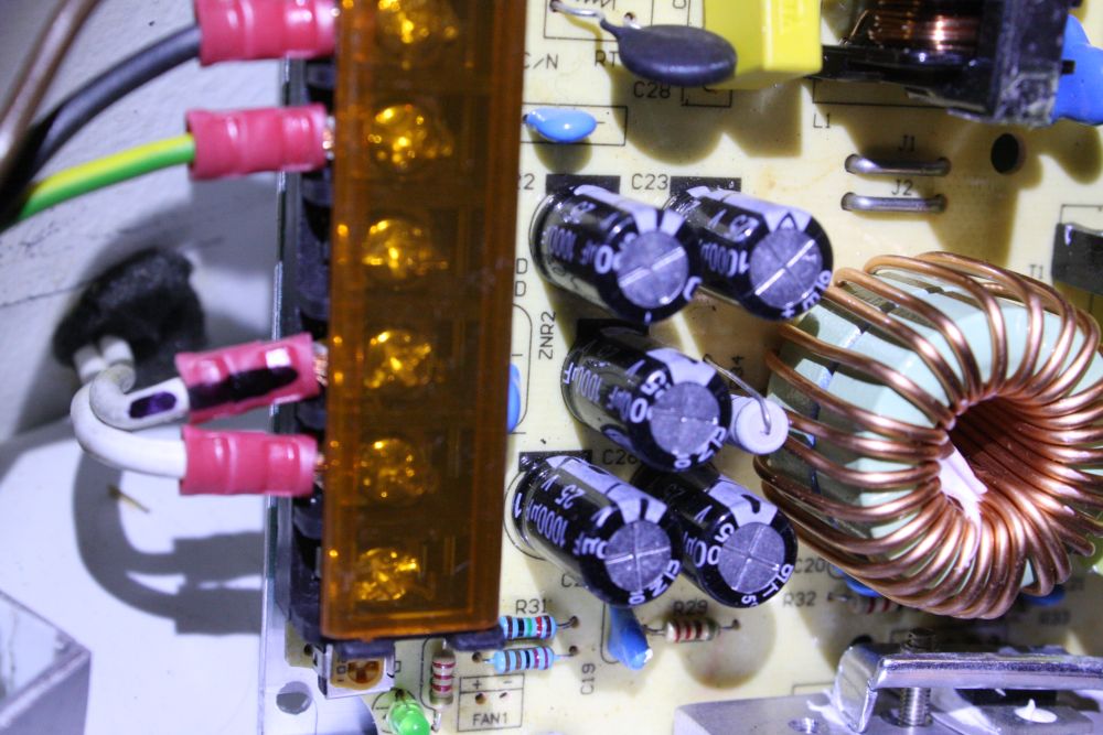
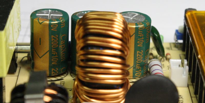 Here it is, can you see the problem?
Those three electrolytic caps are the DC output filter caps.
It's a 12V supply, so they should be rated at least 16V.
But they are rated 10V.
Wow. That's taking cost-cutting way too far. These caps are extremely likely to fail relatively quickly. I can easily change these in my supply, but what about all the other people with one of these? It's not FlyingBear's fault, since they didn't make this supply. But it's going to be a hell of a support headache for them.
I wrote to them, they were already aware of the problem and have switched to a different power supply manufacturer.
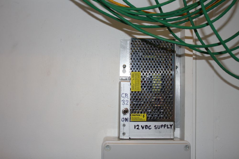
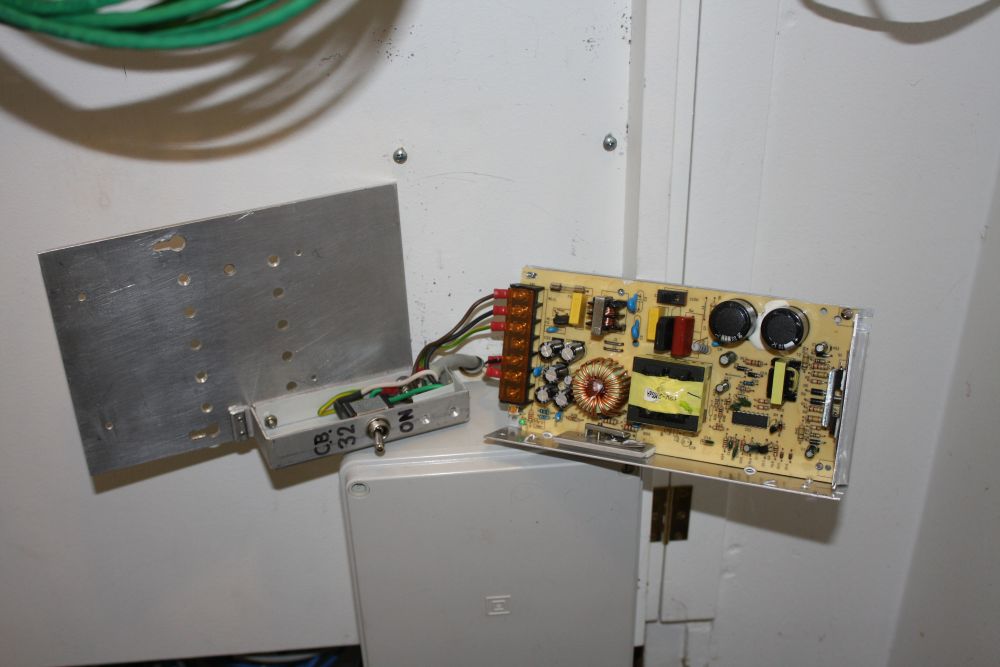
Meanwhile, hmmm... I have another 12V DC power supply by that same manufacturer, built into my workshop's wiring closet. Better check it.
 |
 |
 |
 |
At least that one is OK. The output caps have 25V rating.
Not so lucky with getting a replacement for the dead transistor. It's a 3DD13009K, and AliExpress list multiple sellers. I ordered from one, and then... that seller still hasn't shipped, 6 days later.
When I ask the seller if I should cancel the order they replied "No We are trying to send."
Good grief, what does that mean? Can't fit them through the door? Someone glued them to the shelf, and we are trying to pry them loose?
Hopefully not "We are having someone make some fake ones, ready any minute now" like actually happened — funny story.
 For those using this supply, I recommend opening it, checking for potentially intermittent solder joints, and definitely changing those caps for ones rated 2200uF, 16V or 25V.
The 25V ones (what I could find quickly) barely fit, and you have to move R44 (270R, 2W) out of the way.
Well, I guess since FlyingBear changed to a different power supply manufacturer, this schematic of the one I have won't be so useful. But here it is anyway, for those who do have this one.
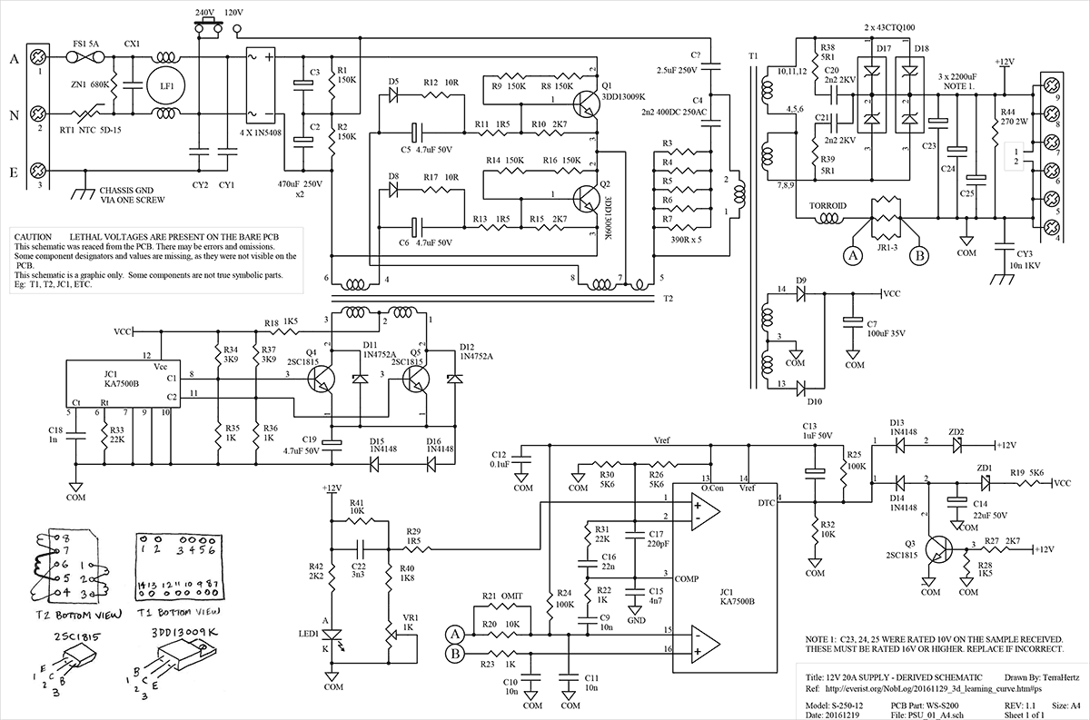
Also the same, as a PDF, and the schematic and component library files. (Protel98)
Continuing