After finishing the Metal Folder Base and mech-workshop upgrade, what to do next was a difficult choice. Mainly because there are so many things on my to do list that it's hard to prioritize. Several projects are in the air, but all wedged with problems I couldn't yet solve. Like the microscope LED light, stuck because I can't find a source of the small parabolic reflectors it needs. And another project involving modifying a scanner, that is wedged till I get a working microscope & camera setup going.
On the other hand, there's the general 'get my lab functional up to where I can work on the main project' objective. For this there remain a lot of chores. One of them is to further rationalize storage organization and at the same time get rid of some excess junk that is taking up space.
 Not much planning needed for this; it's just a kind of bubble sort algorithm. I have a fair idea of where things should end up, so the plan was to repeatedly sift through the stuff moving things to more appropriate places.
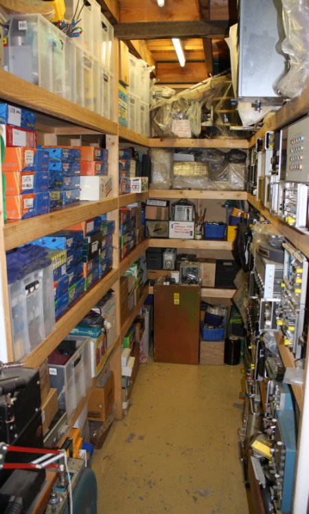
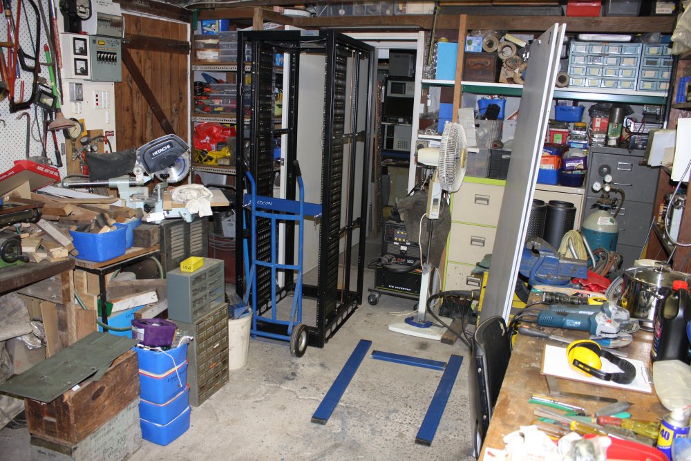
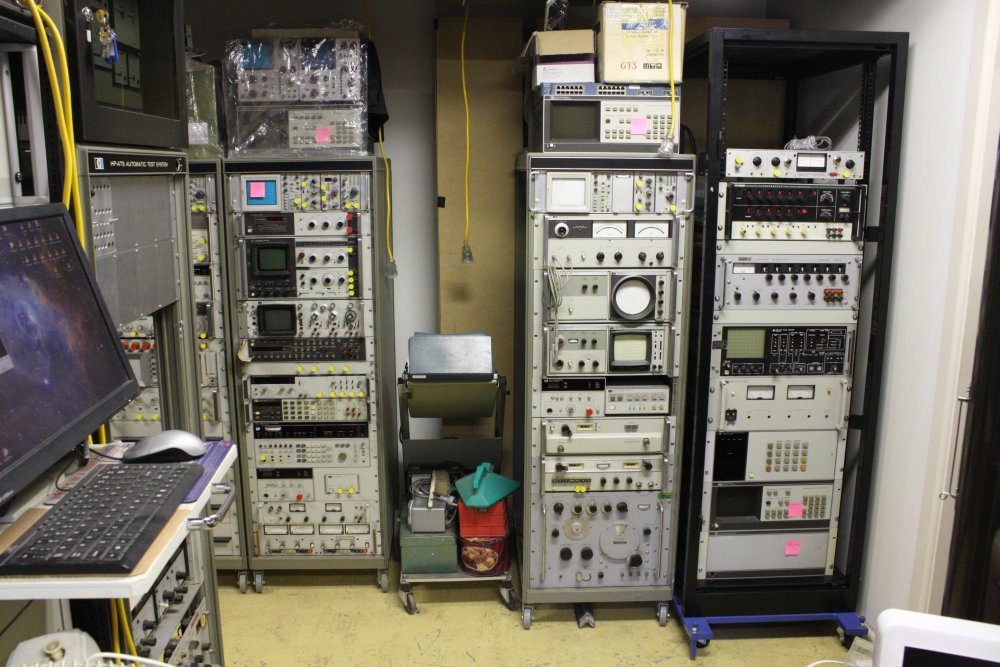
A vague and open-ended process, and you know how those things often go. But at least one of the storage areas (at right) is already a lot better. Couldn't even get in there before.
Also there'd be other things I could achieve at the same time, such as:
- Finding and putting aside items I should dispose of, and then disposing of them.
- Collecting all the old vacuum-related gear I have, into one place so I can begin to work out what's usable for the vacuum system project, and what isn't.
- Small fixit jobs on things turned up during the sorting.
Not so much a 'project', as a demonstration of the usual state of affairs around here.
Chaos.
The AC Meter
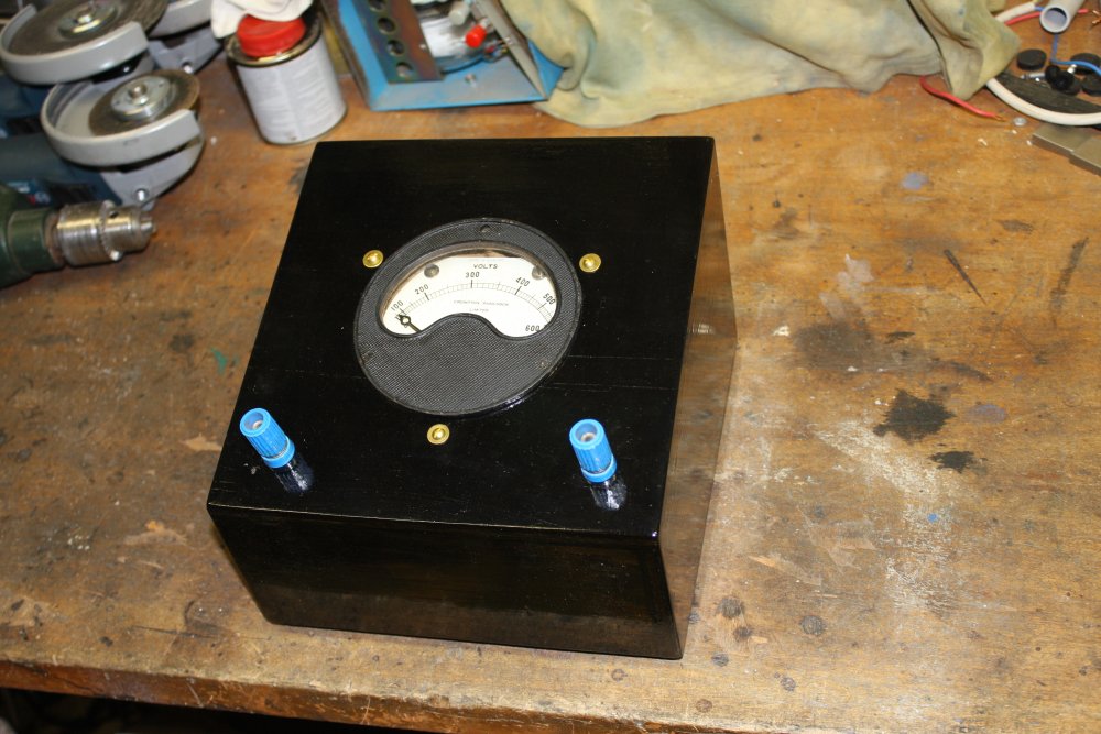
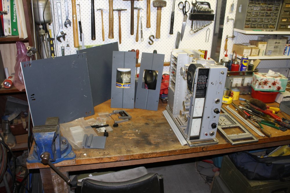
For instance: I come across an old moving coil AC voltmeter in a wooden case. It's primitive but I like it, partly for antique appeal. It deserves to be among the 'ready use' test gear.
 However the case is filthy — faded and stained clear lacquer. So now would would be a good time to fix this thing up the way I'd like it.
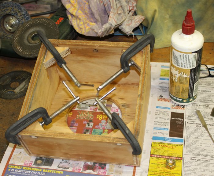
Apart from sanding off the old lacquer and woodfilling damage and unwanted holes, the base is badly secured. So I cut some corner pieces and glued them in.
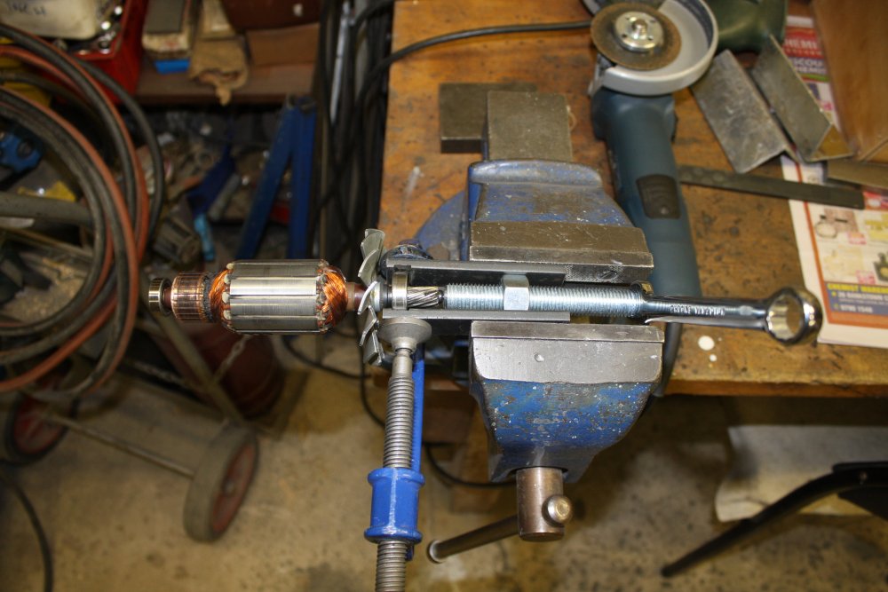
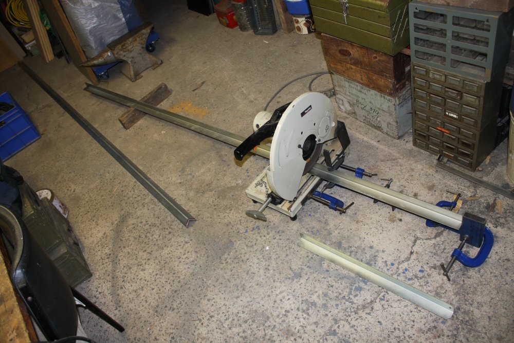
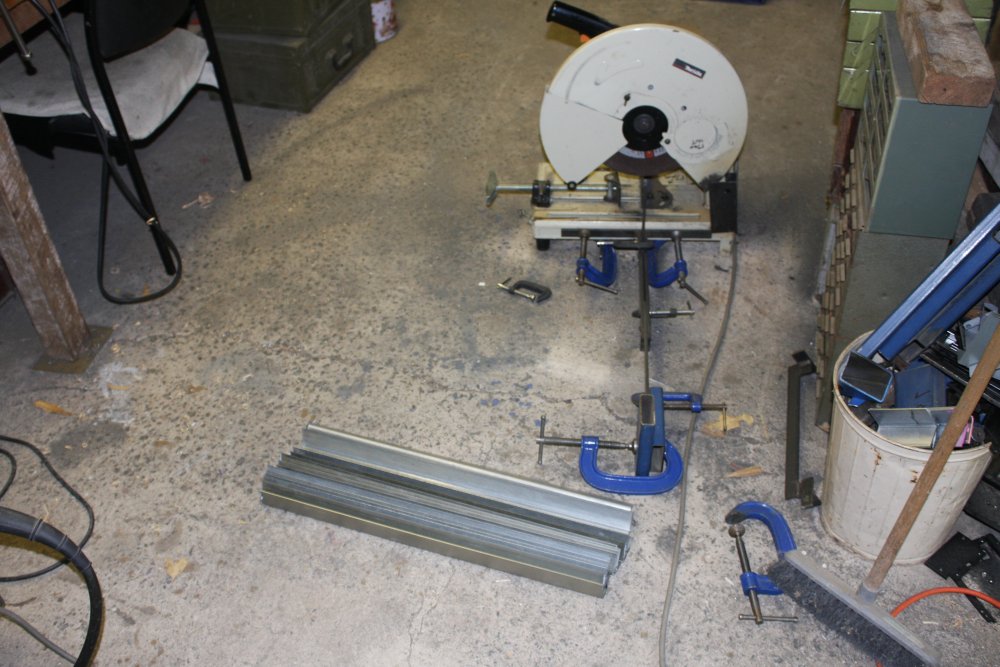
While cutting those, my miter drop saw main bearing seized. Again. It's done that before, but I was able to work it free. This time it's really stuffed, and keeps jamming again.
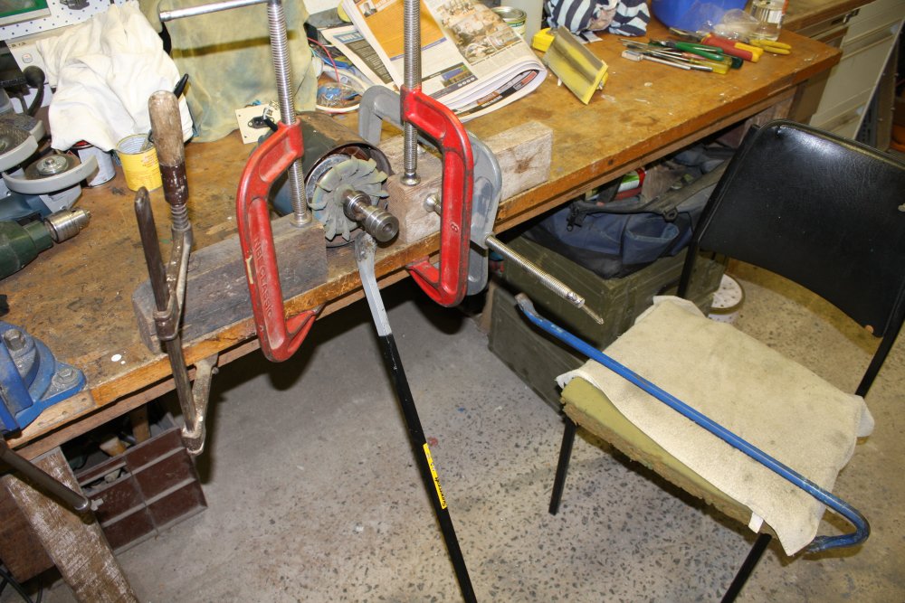
Disassembling the saw motor is easy, but pulling the press-fit bearing off the shaft is not. That's why I didn't replace it last time. The bearing puller I have cannot work on this little bearing. There's no solution involving hammering or levering, as they'd damage the armature.
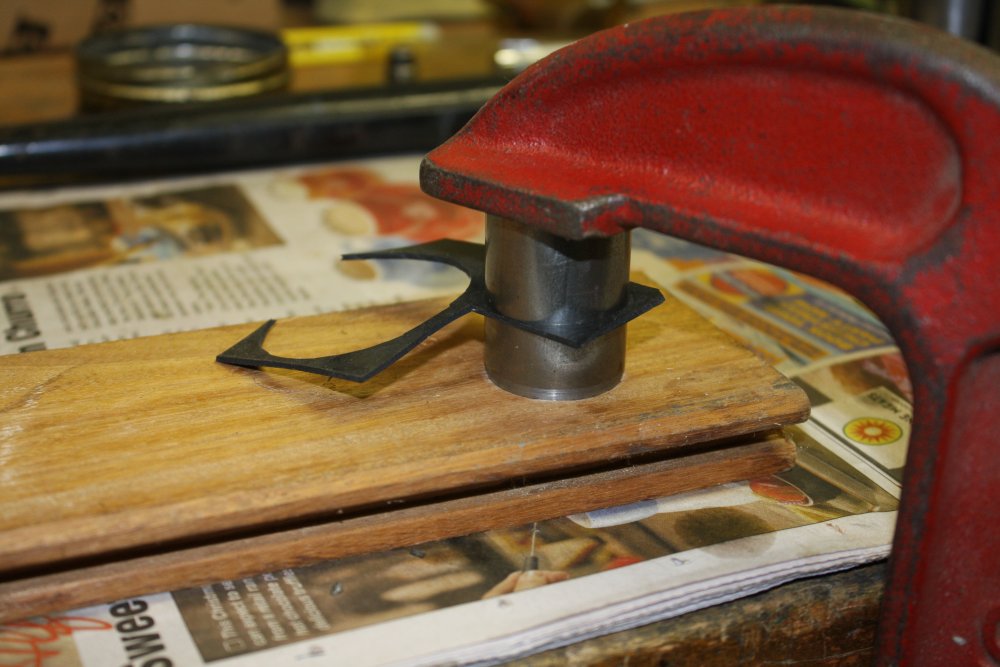
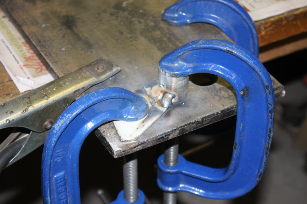
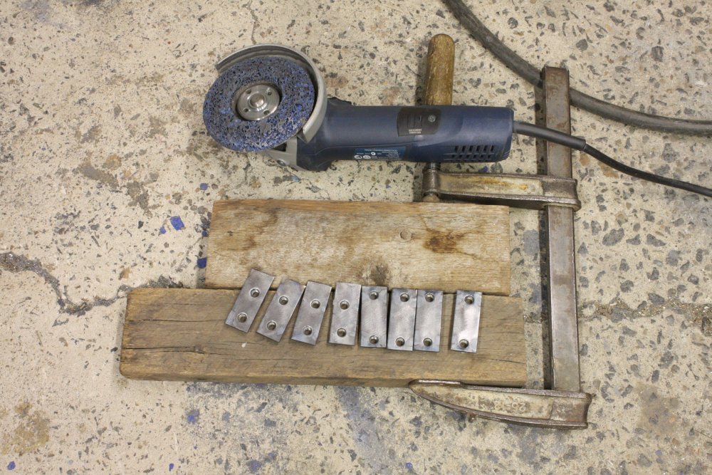
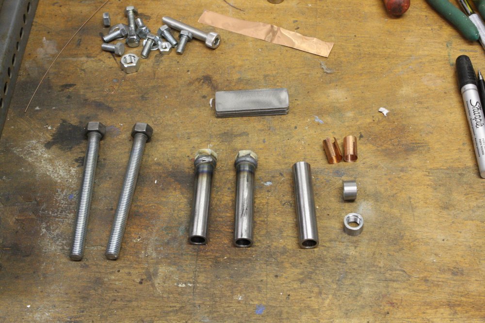
OK, what's the quickest way to improvise a bearing puller?
 |
 |
Something like this, I think. Anyway it worked well. I had another bearing the same size, and pushing it onto the shaft with the vice was easy. So that's the saw fixed.
After opening up the bad bearing I can see why it kept jamming. The cage that's supposed to hold the balls spaced apart had been wrenched into pieces, which then would wedge under the balls.
This was before the pic of gluing in those corners. Back to the meter case.
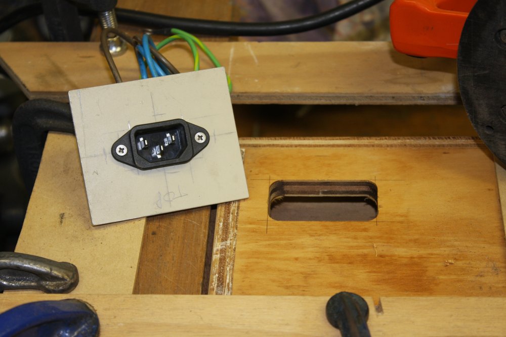
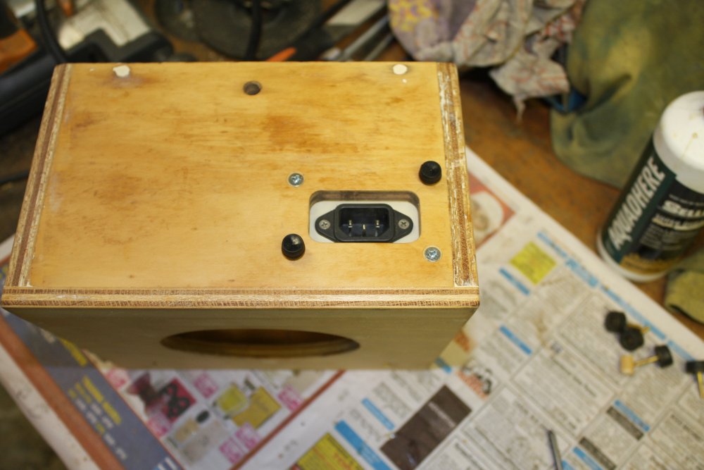
The meter reads zero to 600 Volts AC, and rather than always have to use the two banana screw posts on the front it would be nice to be able to simply plug it into a mains outlet sometimes. Such as the 2nd outlet on my variac. So I decided to add an IEC socket on the back. But... that's a male connector, and if power is being applied by the front panel terminals, the pins of the IEC would be live and exposed. So for safety it would have to be recessed and with a cover when not in use.
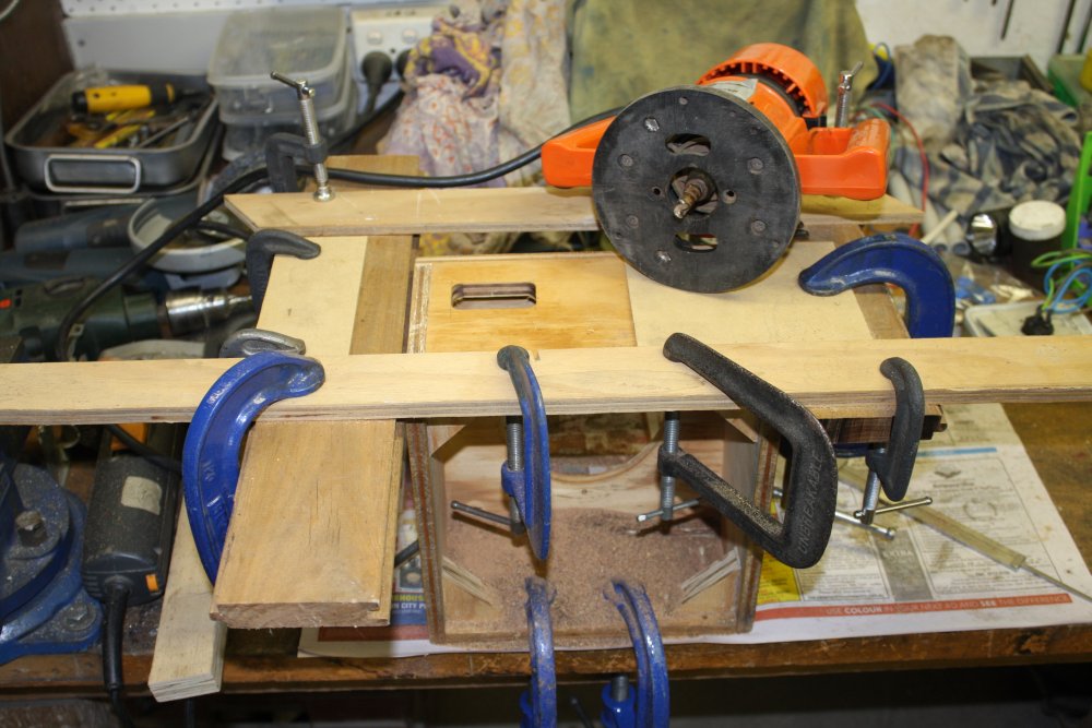
All that wood and clamping above is just to get a nice neat routed hole with straight clean sides.
 |
 |
 |
 |
 |
1 - 2. Mounting the IEC socket.
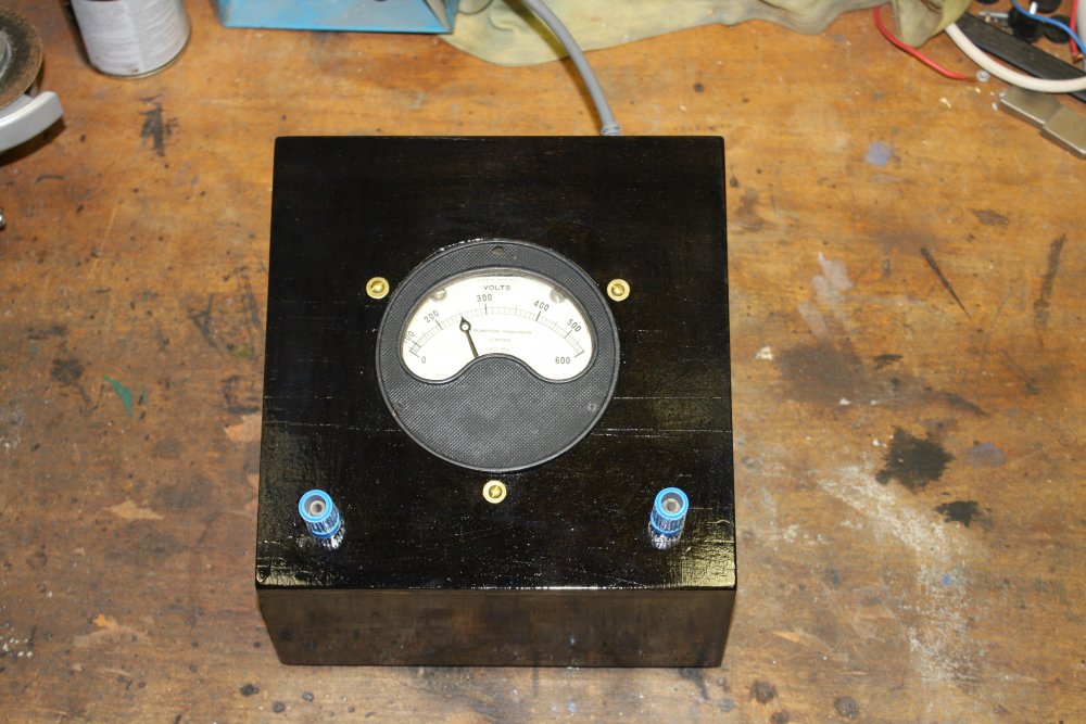
3. After staining (China Black) and a couple of coats of estapol.
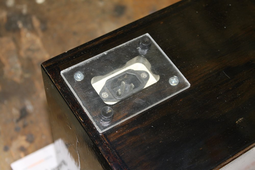
4. Cover on the IEC.
5. Plugged into the mains. Yes, the banana terminals are live too.
Sewing Machine Repair
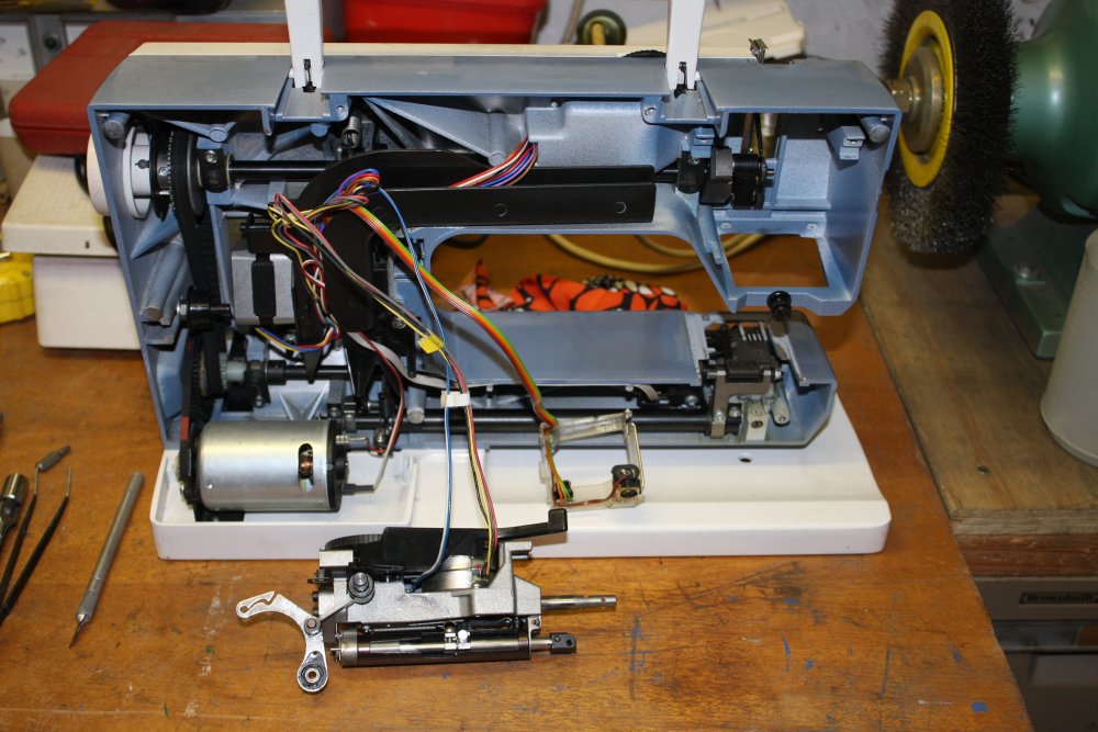
Meanwhile... around the same time my ex-wife found her sewing machine now wouldn't do stretch stitching. "Skipping stitches" was the described symptom. It's a good but quite old Husqvarna, that I'd been maintaining over the years. I had an idea what the problem might be, since it was something that had been getting worse for a while.I find the mechanism by which sewing machines loop the two threads together through the cloth quite beautiful. But it does rely on a very precise alignment of the needle and a tiny point on the rotating bobbin holder. That point (the 'hook') has to catch the small loop of thread that forms at the needle tip just as the needle bottoms and starts back up. All of this while often running faster than the eye can follow.
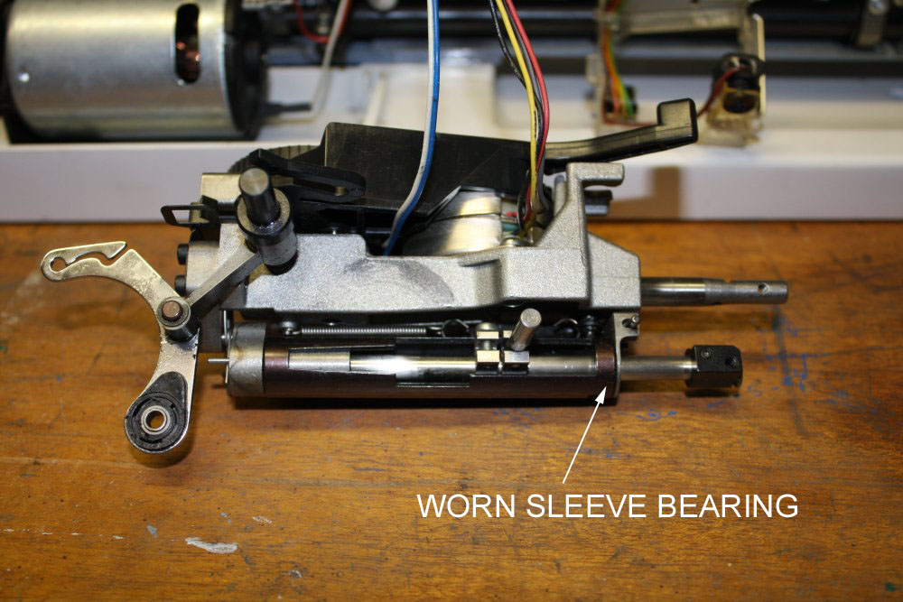
In this model, the reciprocating bar that holds the needle at its tip passes through two sleeve bearings, one at the top of the bar, and one at the bottom, near the needle holder. The bottom sleeve is quite short, so it wears. By now it has worn enough that the needle has too much play, allowing the hook to sometimes miss the thread.
Nothing to do but replace it.
 |
 |
 |
 |
 |
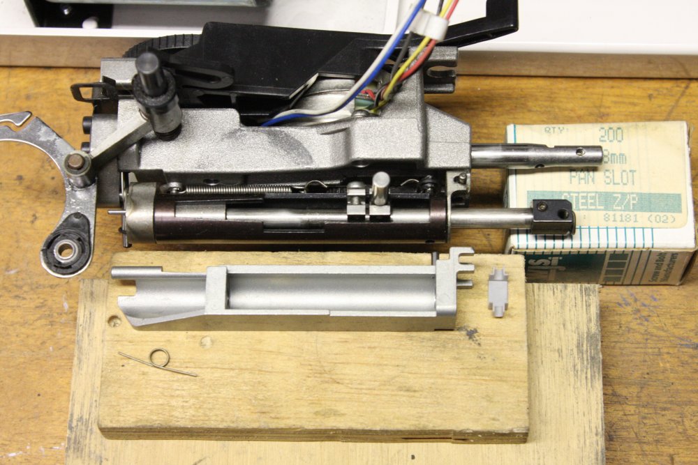
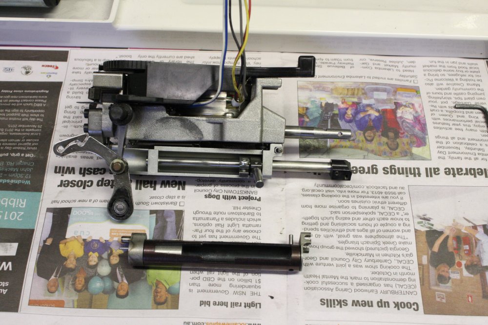
1 - 2. The needle bar assembly removed. When it's in mounted in the machine there's no way to adjust things. Has to be right before mounting. Took me a while to be sure I could get the new part set right.
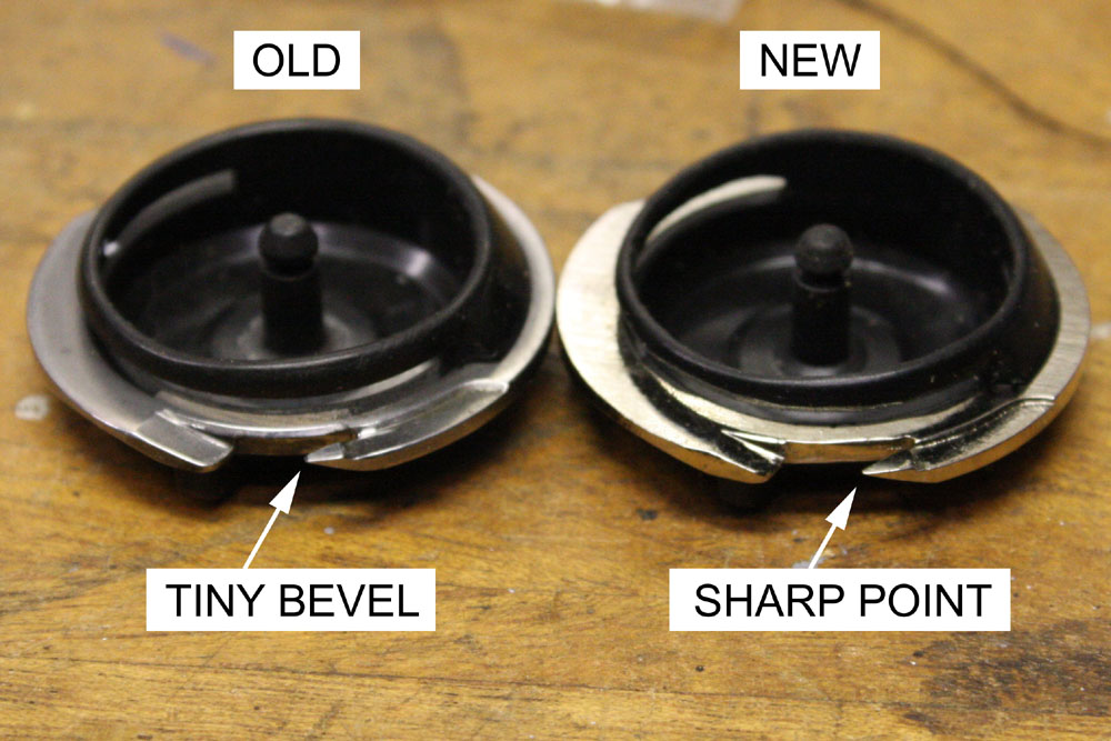
3. Another casualty of the needle looseness. It's been hitting the fine point of the hook, and has worn a bevel on the end. So that has to be replaced too. Husqvarna had one left in stock, and it's an obsoleted part.
4. When I went to pick up the parts, there was an 'oh no, it's wrong' moment since the needle bar holder looked radically different to the old one. But on comparison, they are functionally the same. Phew.
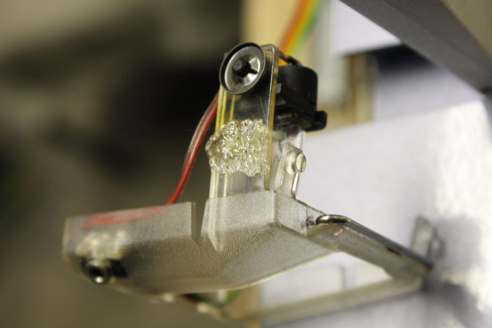
5. Plastic gone brittle with age and heat. This piece holding the light snapped. Here's some rough plastic welding with a soldering iron and some scrap plastic of a similar type. Not visible in use, and it works.
 |
 |
 |
1 - 2. New part in place. After reassembly there's one adjustment for the clearance between needle and the hook. It's supposed to be as close as possible without actually touching. With the new bobbin-holder/hook, rigid needle position, and a general clean and oil, the machine runs like new.
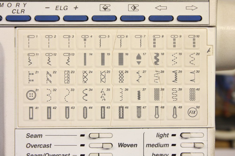
3. Except it isn't, of course. Here's the next job I can see it needing soon enough. This is a keyboard, with a flexible thin elastomer printed front, then plungers to actual buttons. The cover membrane is breaking up, so I photographed it in high enough resolution that when needed, I can replace the membrane with some ink-jet printed and laminated look-alike.
Finally in place
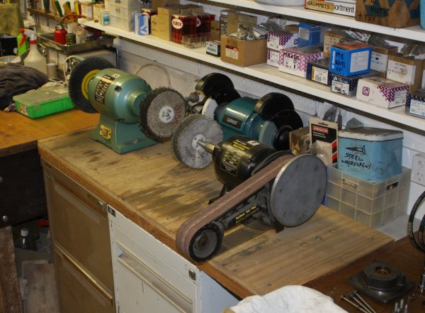 When moving things around in the mech workshop, the belt sander and polishers' placement on their base was wrong for the new arrangement. I'd unbolted them, then dithered over where they should be. Using them when they're not fixed down is a pain, and I do use these pretty often.
At some point long after it should have happened, I drilled the holes and bolted them down.
At last I have clearance to the right of the belt sander, and can fix a sanding disk to the flat end face like it's supposed to have.
Street toss disassembly
As usual I can't resist picking up street-tossed tech. At the moment a quite nice photocopier and two tower PC cases were taking up floor space. The copier was pretty much working, possibly just low on toner, or a problem with a corona wire supply. I decided I wouldn't bother with it. The PCs were tower cases and had motherboard problems, but I'd only grabbed them for the hard disks and case sheet metal anyway. So these all got the chop.
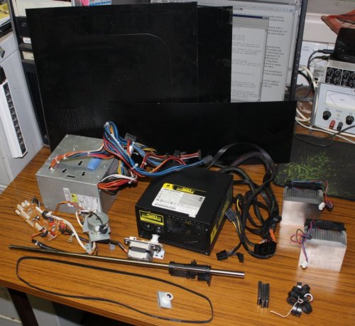 The PCs provided two good power supplies (one a really nice upgrade), a couple of big CPU heatsinks and fans, two AMD Athlon 64 CPUs (for my CPU history collection), DVD burner drives, a floppy drive, and two working SATA hard drives (70 & 40GB) which are useful for data backup. HD's also provide some interesting data archaeology fun, not least in other people's music tastes.
Also some plain sheet metal pieces, now that I'm aware I can cut PC cases up easily with my big guilotine. Those go towards another unfinished project that needs a few more such sheets.
The copier provided the usual assortment of motors (stepper and DC), toothed belt, circlips, steel shafts, ferrite cores, glass sheet, springs, wire, etc.
Disposable? Or not
Things I came across that I thought I should get rid of, included:- A Racal-Dana 9084 Synthesized Signal Generator
- A Racal-Dana 9000 Microprocessing timer-counter
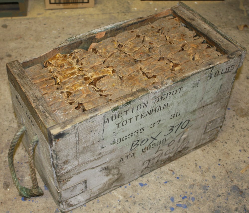
- Wooden crate of 1/2" BSF Button Dies, NOS, Qty 416 (See ebay 191745349784)
- A very old Edwards SpeediVac rotary vacuum pump.
The Racal 9084 is an old but quite nice signal generator. Unfortunately it has a fault and I never could find a service manual and schematics for it. Which makes it effectively junk.
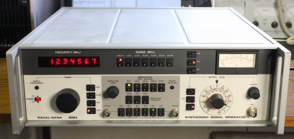
I've been looking for a manual for years, without success. I did fix a power supply problem it had, but there's still something wrong in the synthesizer section. Time to give up. I have other better signal generators anyway.
But, it seems I can't even give this thing away. One last try via ebay; if that fails I'll scrap it for parts.
Update: It sold for $20.50 (two bids, ha ha), to someone who intends to try and repair it. And who probably has a good chance of succeeding. I'm glad.
The Racal-Dana 9000 Microprocessing timer-counter I thought would be a similar story. It's been sitting on a shelf for years and I can't recall if I'd ever tried plugging it in. I had searched for a manual several times over the years but found only one, which appeared to have been scanned by an idiot. The 'schematics' pages were botched, with only fragments of wide foldout sheets captured, making the file useless. It's mystifying how anyone could do it so badly, and think it was adequate. Then multiple sites all copied that same 6,487 KB file. These:
http://www.ko4bb.com/manuals/index.php?dir=Racal
https://doc.xdevs.com/doc/RACAL/RACAL%209000%20SERIES.pdf
This kind of rubbish is why I get so annoyed with people who claim "paper manuals are obsolete, it's all online nowadays." To which the only appropriate reply is a raspberry.
Now I had one last look for a usable manual, before ditching this instrument. And... lo and behold, found one! Size: 31,977 KB. Has an annoying banner page, is fax mode, some schematics are rotated 90deg, some are broken into parts, and of course it's pdf and painful to work with, but it's usable and seems to be all there.
Well then, I should at least power it up and make a quick effort to get it going. So I can describe the probably multiple fault(s) in an ebay listing.

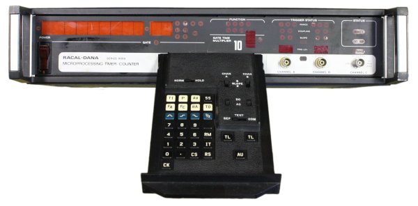 It has an unusual front panel, in that all the controls are on a small slide-out drawer.
Very klunky and eccentric, which kind of appeals to me due to rarity factor. Lucky it's unlikely to be easily repairable, or I'd be tempted to keep it!
And the aim is to get rid of it.
Definitely.
As with any old, long-unpowered electronics, I started it up on a variac, beginning with zero mains voltage and winding it up slowly. This is so things like old depolarized electrolytic caps have a chance to reform, and any catastrophic faults don't get a chance to destroy surrounding circuitry too. Theoretically.
It seemed to be going OK, with some LEDs starting to light up and no dramatic current draw increase, when it suddenly died. Blown fuse. Sigh. Was it a bad fuse, maybe died due to corrosion? It didn't appear so. After a hunt through my poorly sorted fuse collection for a 750mA fuse I replaced it, tried another slow power-up. This time the fuse blew almost immediately. Phooey.
Some multimeter probing found two diodes, CR6 & 8, for the -12V rail, short circuited. (Page 6-9 in the manual.) Replaced them and the fuse (again), retried. It starts to power up, then dies again. Same diodes and fuse all dead. OK... dammit. I had a pretty good idea of the suspect, and yes, it was a shorted tantalum cap. I replaced it with a new one from my (old) stock of tantalums, replaced the diodes and fuse again, tried re-powering it. This time it came up to full voltage OK, and ran for about 3 minutes. Then the 'new' tantalum I'd put in failed, taking out the diodes and fuse again. Arrrgh! I hate tantalum capacitors.
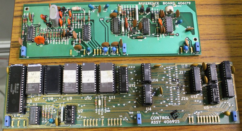
After replacing them all again, it stayed up. And surprisingly seems to be all working. Which meant this was a good time to archive the EPROM images. Here they are. 8KB Zip.
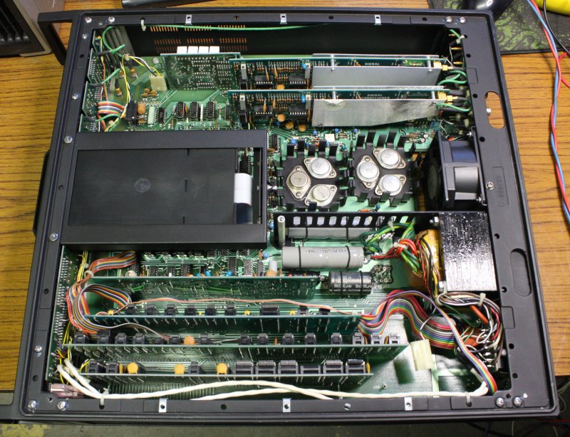
The controls on a drawer isn't the only slightly odd feature. There's facility for inputs via either the front or back panels. That's not unusual, but the method used to achieve it is. The two input cards near the top above, can be unplugged, rotated 180 degrees, and plugged in reversed. Different pins on the motherboard, but why didn't they just provide long enough coax leads to reach either the front or back panels?
Then there's the card connector system, via thin gold plated pins sticking up from the motherboard. Consequently when inserting a card you have to be extremely careful to ensure all pins have actually entered their correct sockets on the card, before pushing it down firmly. Or else you'll wreck the delicate pins on the motherboard. Note that some of them can't actually be seen without a torch and dental mirror.
This is one oddball piece of gear. I like it.
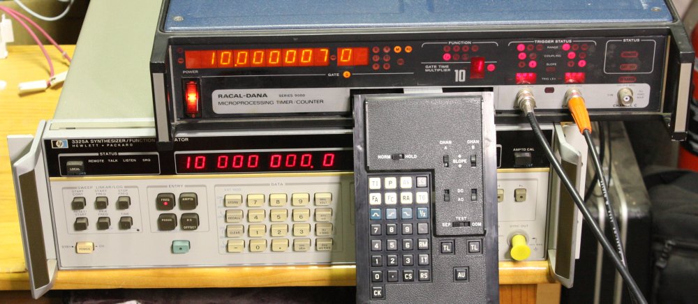
After discovering that it works and is reasonably accurate despite not having the low drift reference oscillator option, and there are even more quirky features in how it operates, I decided I liked it too much and had to keep it. Darn it.
One feature that I'm not sure anything else I have does, is calculating the ratio between two input frequencies. But mainly, the drawer. And that the unit does nothing at all until you pull out the drawer and tell it to auto-setup. After every power up. Ha ha ha...
Well, on to the next thing.
 |
 |
 |
 |
Why did I even bother picking this up? It was among junk in a building some friends and I were helping clear out for a commercial tenant after their lease was terminated due to the building being soon to be gutted to turn into units. It's a wooden crate of thread cutting button dies. One of two, but the other box was mostly empty and contained an assortment. This one has all the same dies. 416 of them. Too bad they are all imperial 1/2" BSF, 16 TPI. I might use one or two of these in the rest of my life, but 416? Ha ha... and it weighs 38Kg. Yet being something of a tool-head, I just couldn't leave it there. Also, it appears to be a WWII era relic, so there's history too. This one crate full would probably have done to make an entire nation's wartime supply of 1/2" bolts. Maybe there was another, and this was the backup? So much effort in making these!
The saddest thing is that if someone wanted to buy just one button die like these, on ebay it would cost at least $10. Or $17 from a tools supplier like Hare & Forbes. But who's going to want 416 of them? No one. Perhaps if they were some useful metric size thread, instead of an obsolete Imperial size. So it's turning out rather difficult to sell. I couldn't be bothered trying to sell them in ones and twos. Presumably at a low enough price it will go, but I sure wish I could get something like true value. Not going to happen though.
So that's three fails out of three so far, in this plan to dispose of stuff. In disgust I went on to the next.
The Pump
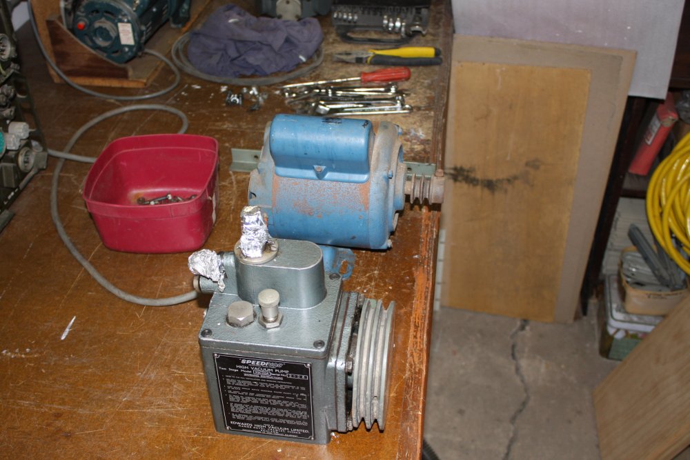
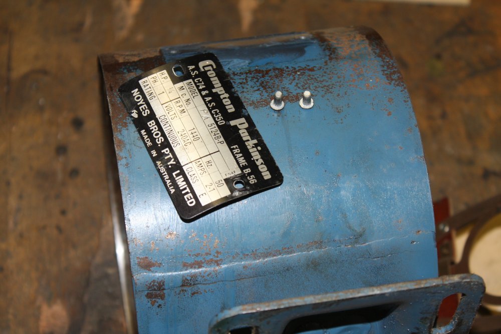
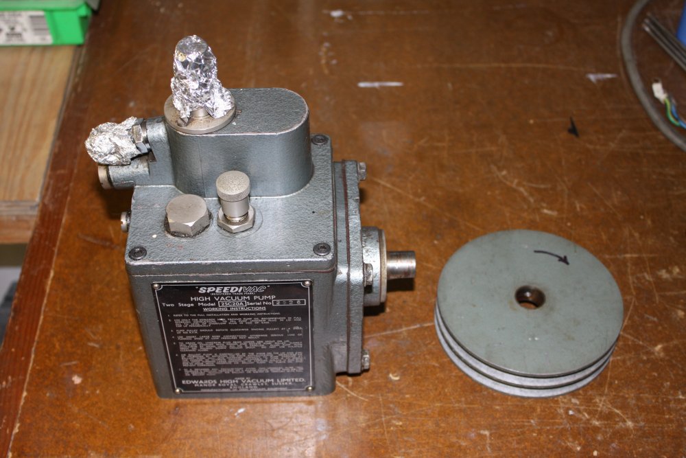
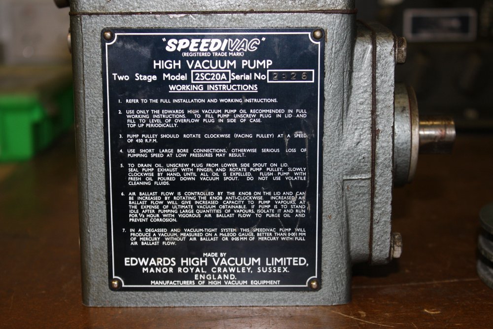
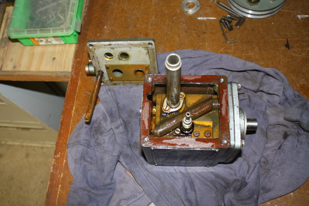
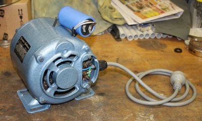
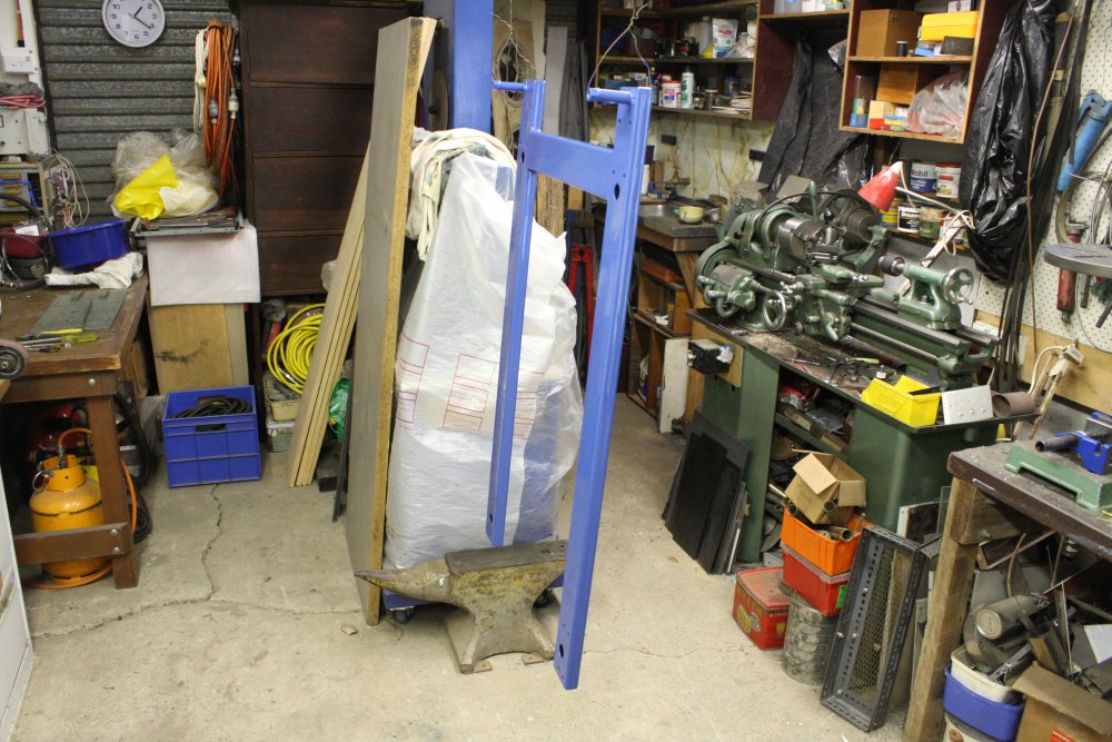
That 'main project' I mentioned involves a large vacuum chamber, and associated pumping systems. It's something I've been working towards slowly for many years. See Last Rack Bender, HP Racks and Racked Serendipity.By now I have much of what I need (minus a turbomolecular pump, still), hence wanting to get the rest of workshop to the point where I can focus on this project. I also have a few smaller surplus rotary vacuum pumps, not needed for that project. One of these is really old and nasty. It's an Edwards Speedivac 2SC20 — a small V-belt driven pump, that someone once mounted on an improvised base and belt cover. Very improvised. It came with a bunch of other vacuum equipment years ago. I've never used it since I have another small direct drive rotary vacuum pump that served for any random purpose. After the other three 'disposal' failures I was determined to get rid of this. It's extremely cruddy looking and awkward, which are more good reasons to get rid of it. Unfortunately they're also reasons it probably would not even sell on ebay. It was so uninspiring I neglected to take any photos. Busy with other stuff, and also what was the point?
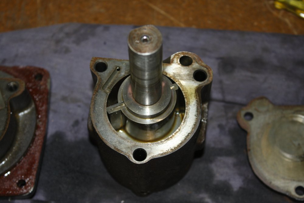
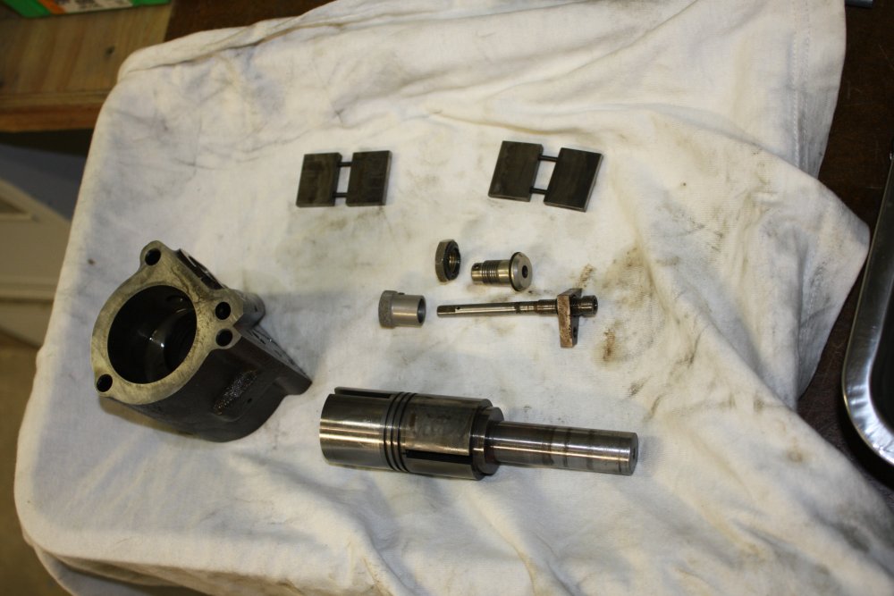
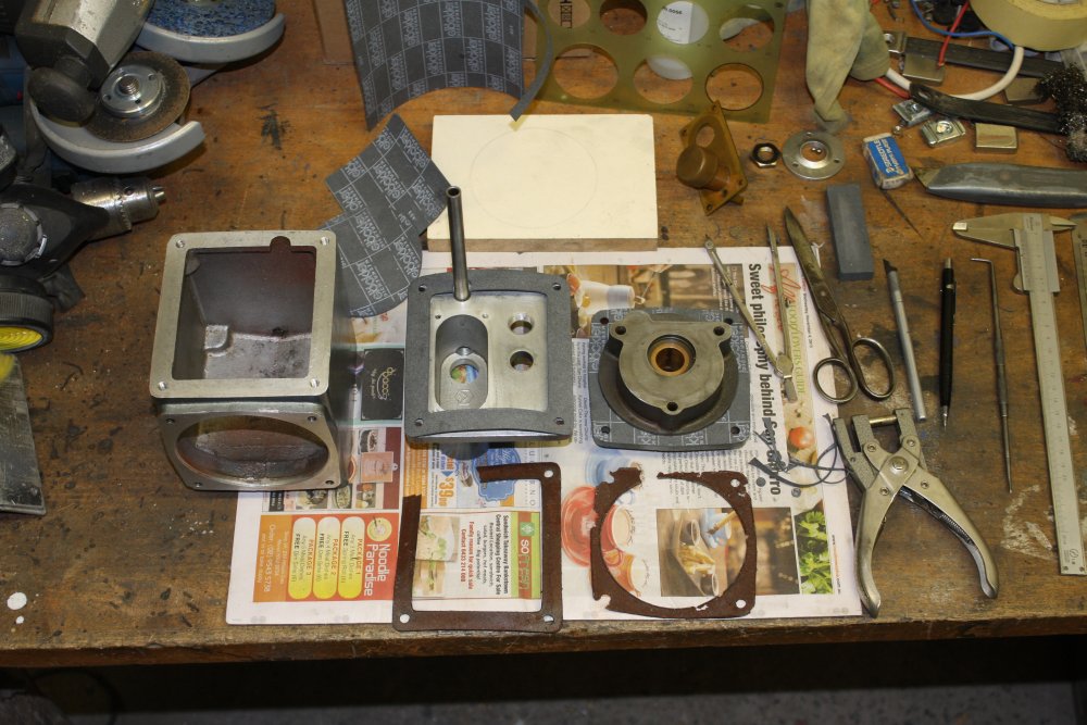
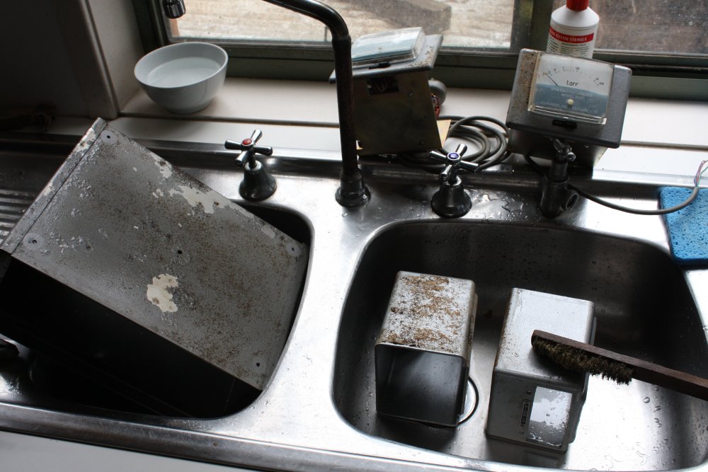
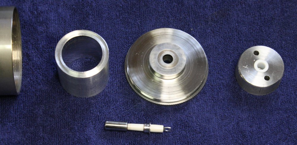
For the rest of this tale though I do need to show what it looked like. So here's the major parts put back as they were.
Which already gives away what happened, doesn't it? Yes, I decided to keep, restore and improve it. Disposal fails: 4 out of 4.
My reluctant reasoning was:
- OK, so it won't be useful for the main vacuum chamber project. But I can think of a few other things I may want to do that would need a small, dedicated vacuum pump. I don't want to need to run the large pumping system or swap piping around for any little vacuum need. So better keep this one.
- A major point... I will need to disassemble, clean and service the larger vacuum pumps at some point. Better to get some experience in doing this one, before risking any of the better pumps under my vacuum-noob attempts.
- If the base and general arrangement of this one were more sensible, it would actually be a quite nice low power consumption pump. I can easily fix that!
- Oddly enough when I was given it there were even two copies of the manual included, together with manuals for other bits of gear. The user manual only, not service manual, but better than nothing. Besides, given its vintage there may not ever have been such a thing as a 'service manual'.
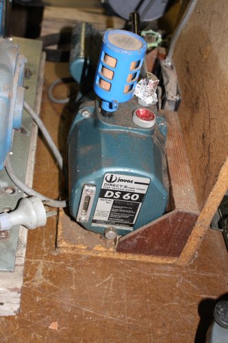 The one portable vacuum pump I have, a Javac DS60, could really do with a better setup. Might as well do that too, since I'm going to do the SpeediVac.
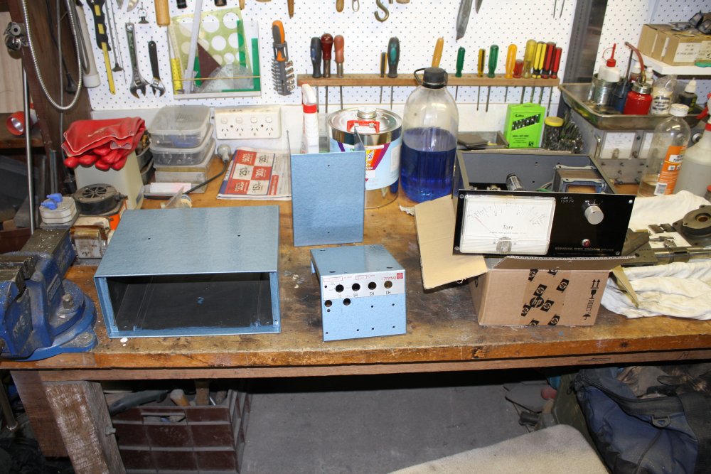
Here's a pic of the Javac; the original Speedivac base is partially seen to the left.
Obvious problems with the Speedivac:
- The crude wooden base that is nailed together and falling apart.
- Between the wooden base and metal plate, there are four 'vibration isolaters'. These were clearly never adequate (way too light duty) and are now completely failed due to the rubber perishing and tearing. The plate just sits on the wood.
- That belt cage! Could it have been any more roughly made?
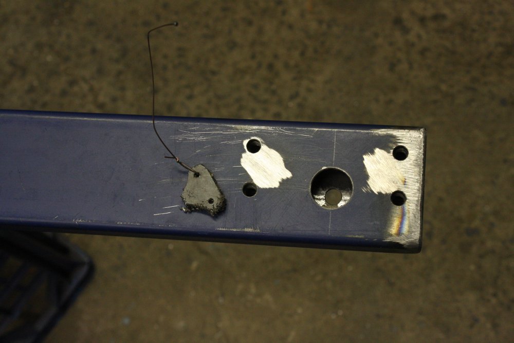
- There are lots of 'historical' excess holes in the metal baseplate.
- Why is it so big? The motor doesn't have to be that far from the pump, and there's excess plate length past the motor as well.
- The belts are ancient, and look ready to fail at any moment. Replace with smaller ones, bringing the motor and pump closer together.
- There's nothing to maintain precise alignment of motor to pump, while tightening the belt by sliding the motor.
- No system to allow easy belt tightening independent of the motor hold-down bolts.
- The motor body is rusty. Needs stripdown, cleaning and repainting.
- Motor cable inlet is hopelessly perished. Replace.
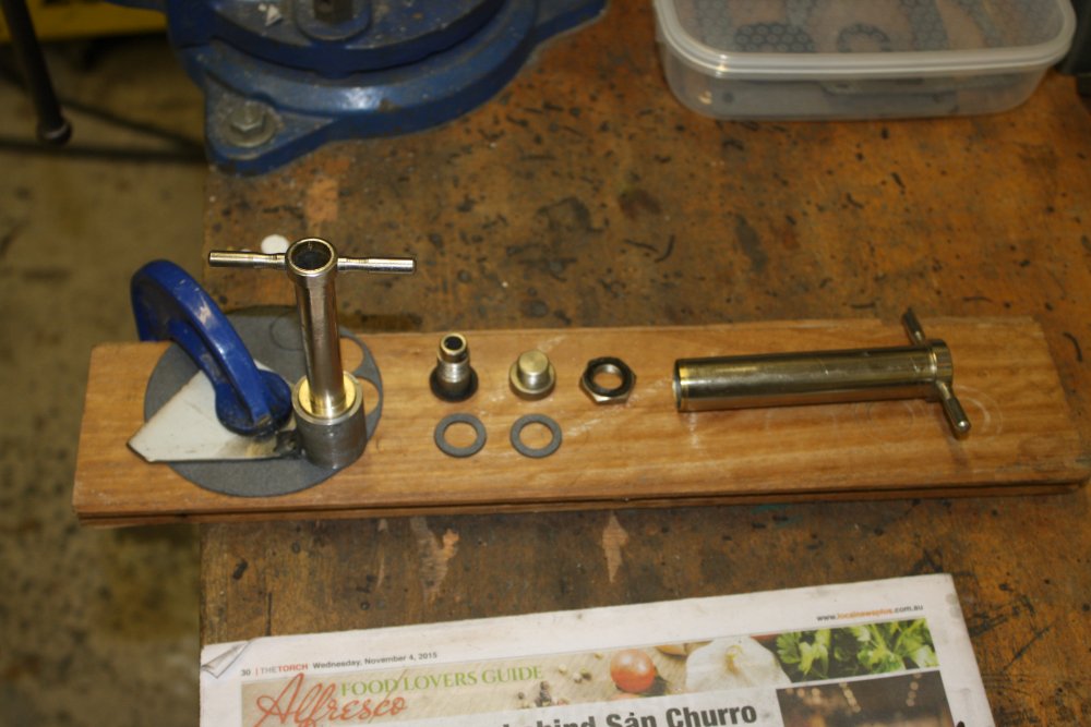
- The pump inlet port is missing its original (obsolete) connection and filter. Replace with modern connector and filter.
 |
 |
 |
 |
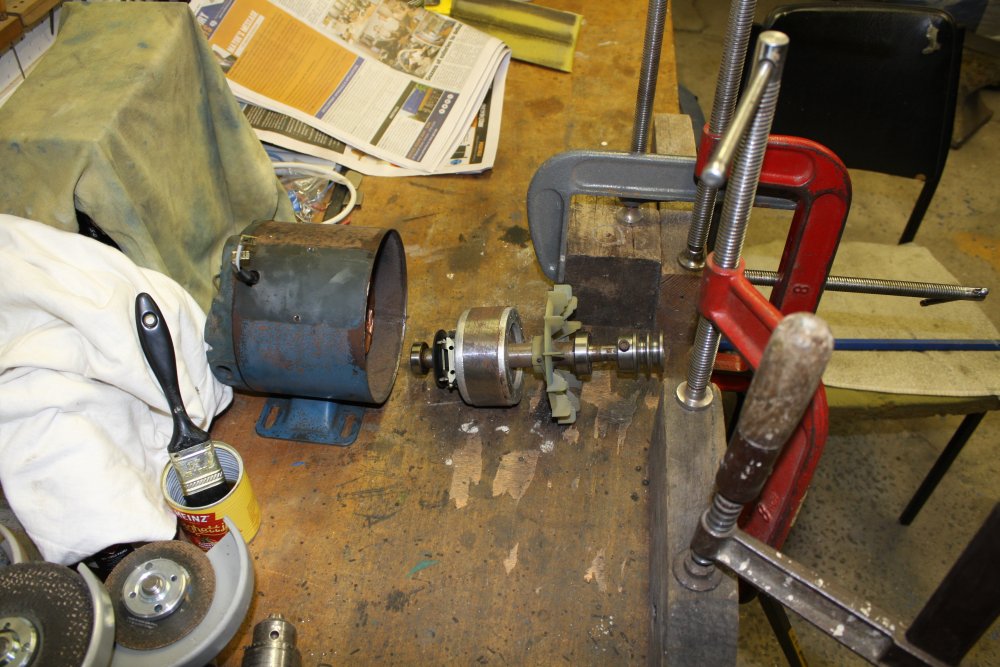 |
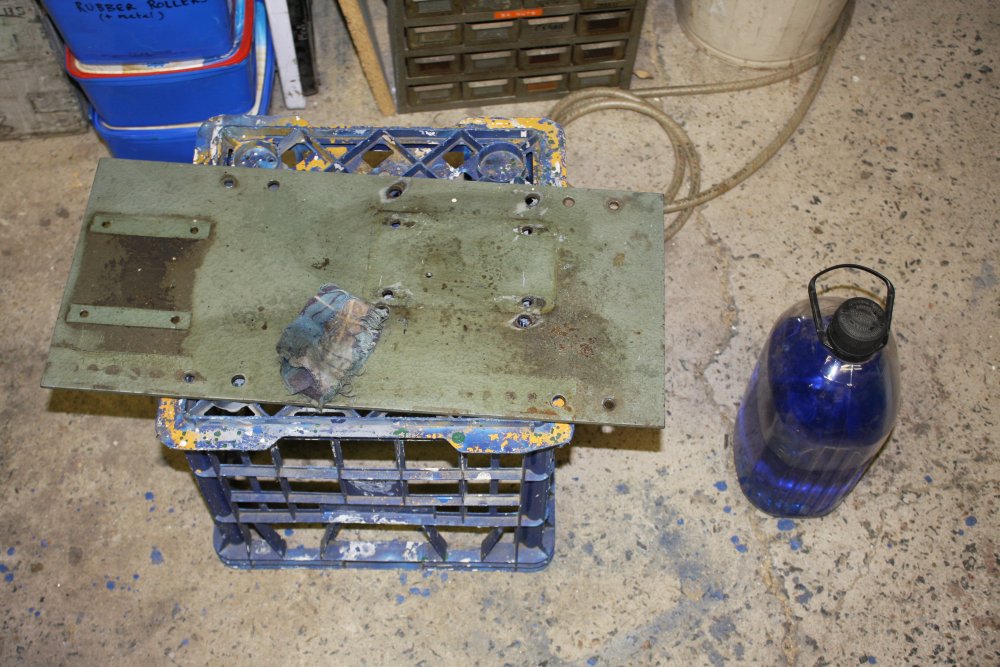
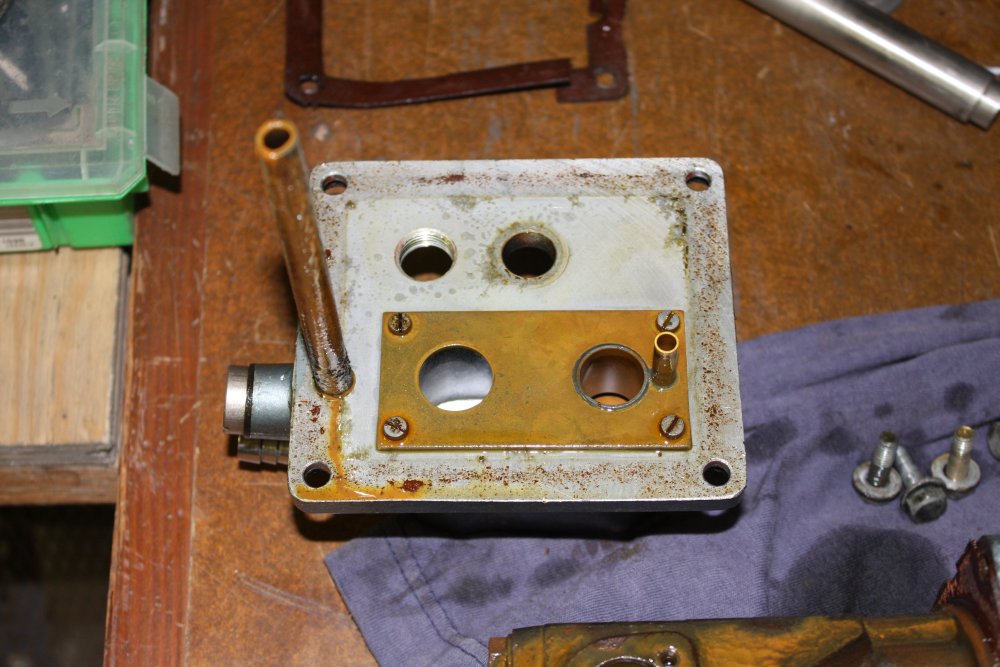
1. This baseplate has seen a few years, and different mounting schemes.
2. So why can't they be closer?
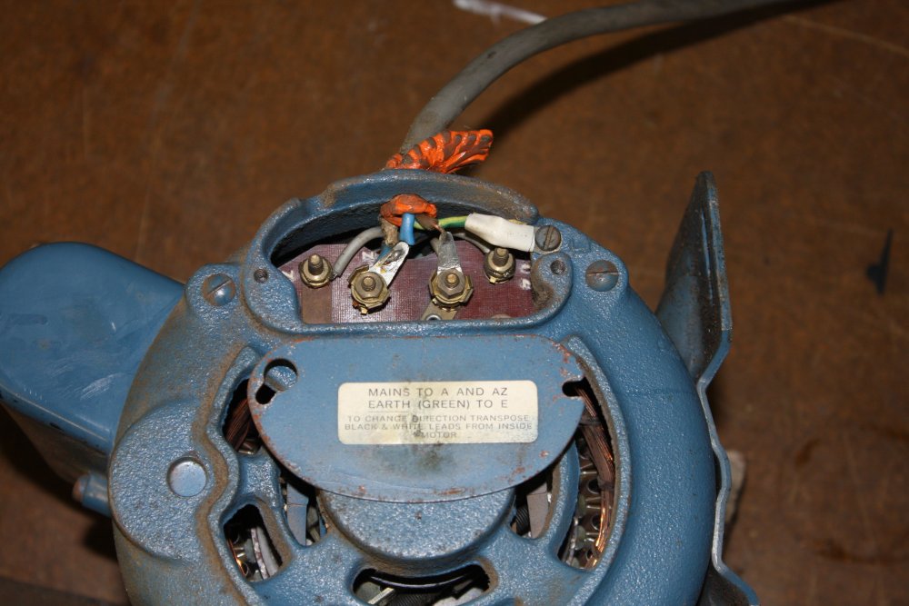
3. Motor needs a new cable entry.
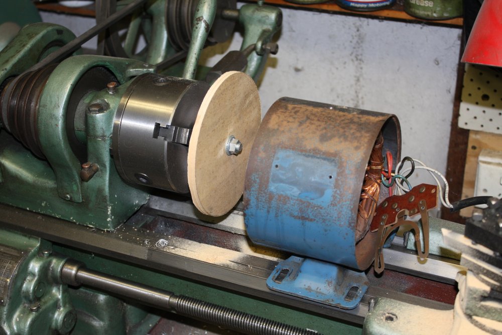
4. Delicately extracting the induction motor rotor, with a crowbar. Let's not break the plastic fan.
5. Success.
 |
 |
 |
 |
 |
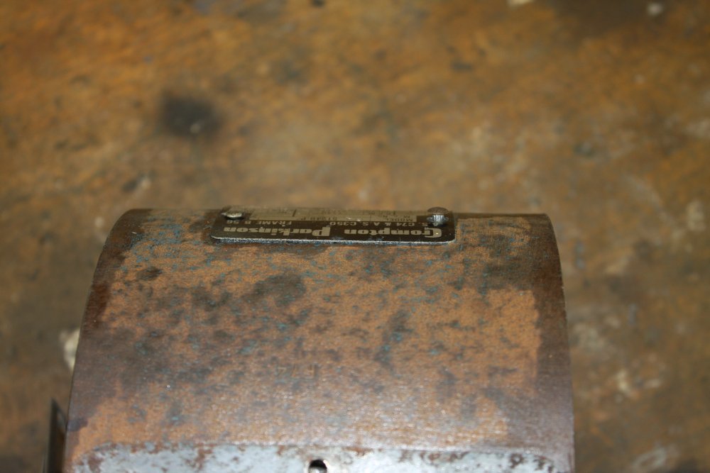
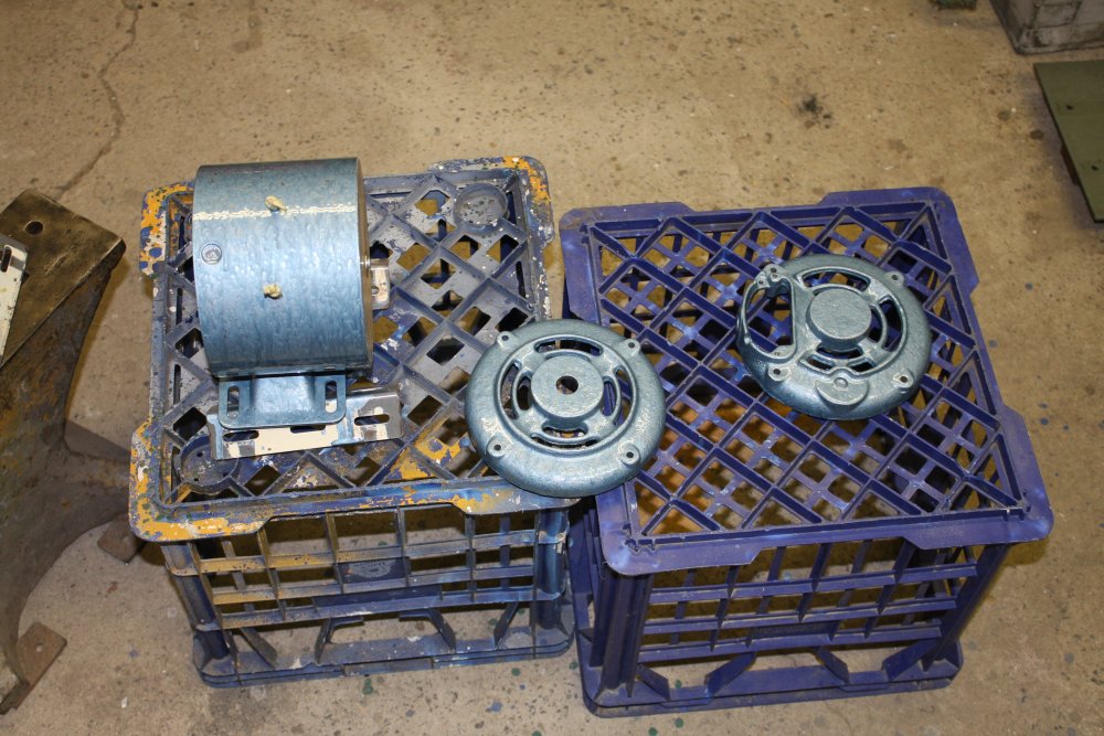
1. The motor label is rivetted on. Pushing out the rivets from inside.
2. Popped rivets. Also shows how rusty the motor was.
3. Label removed undamaged.
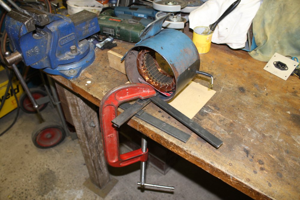
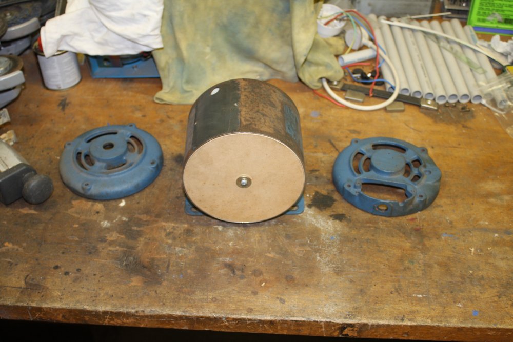
4. Making end covers prior to paint-stripping and rust removal of the motor case.
5. Covers mounted. Do not want to damage the windings.
 |
 |
 |
 |
 |
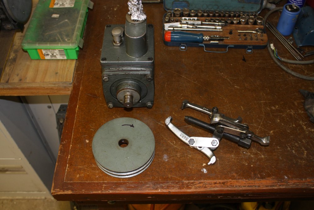
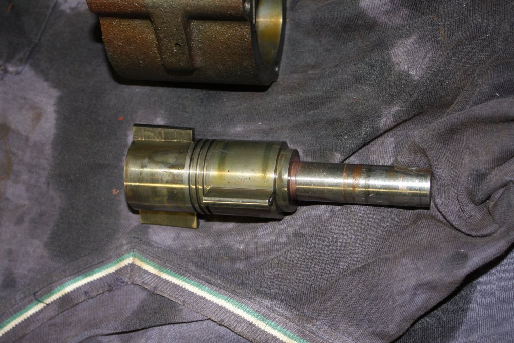
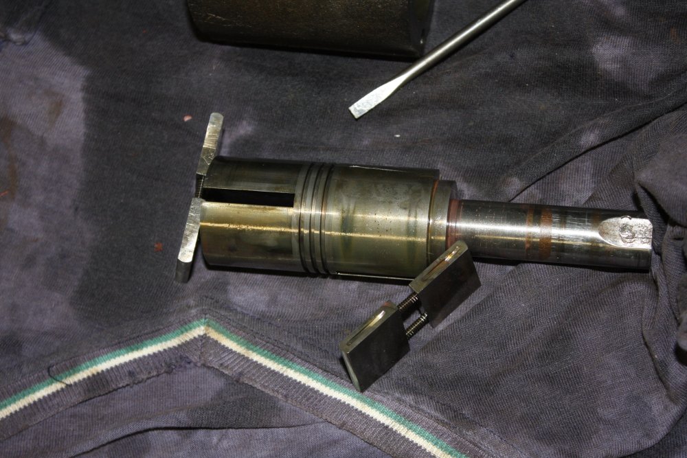
1 - 2. Pump pulley removed.
3. Pump label with instructions.
4. Cleaning the pump pulley.
5. First paint coat on the motor.
 |
 |
 |
 |
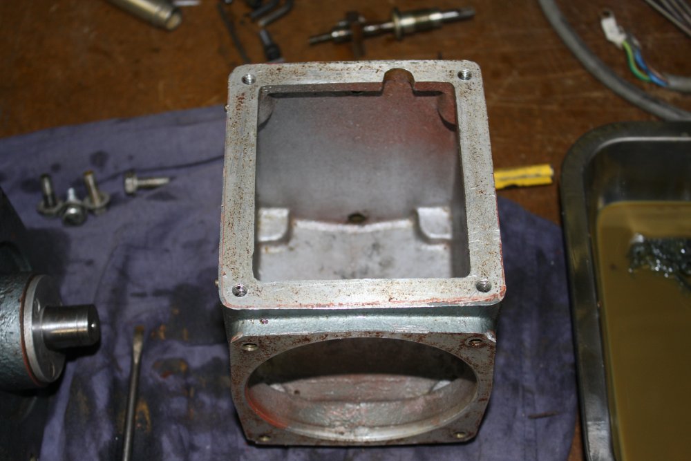 |
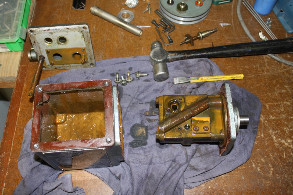
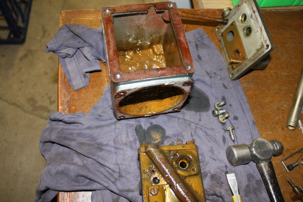
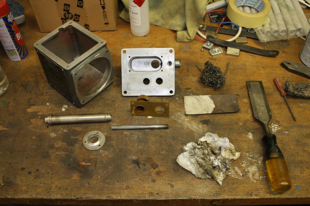
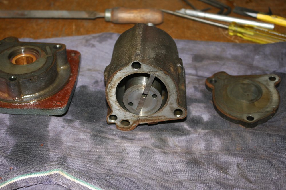
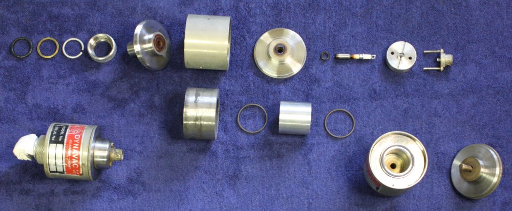
1. After draining the oil, opening the pump case.
2 - 3. Removing the pump body. There's a lot of sludge. Neither gasket survived.
4. Top cover with oil mist catcher and pressure drain tube (which unscrews.)
5. Pump body cleaned with kerosene. 1st phase of cleaning. Volatile solvents cannot be used for final cleaning stages.
 |
 |
 |
 |
 |
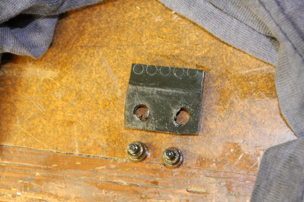
1. The second stage air outlet flap. It's had it — hardened and cracked. Curiously, it looks like for much of the pump's lifetime it was mis-positioned, so the edge didn't fully cover the outlet holes.
2. Cleaning, cleaning. Gasket residues removed.
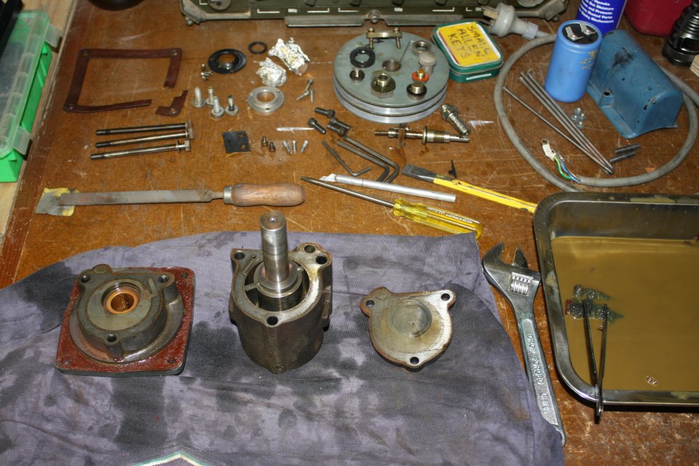
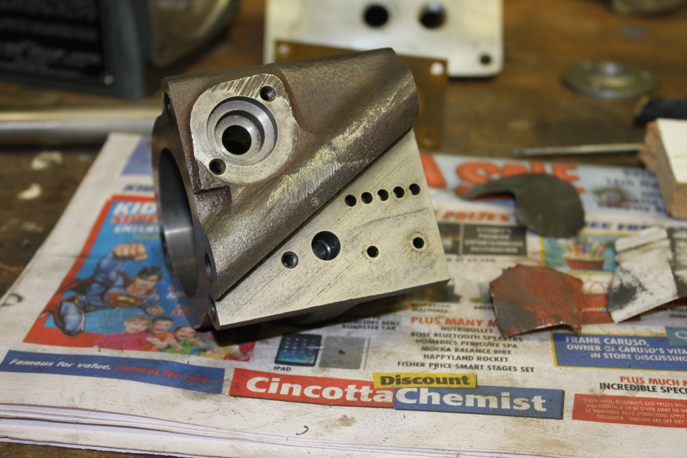
3. Starting on the pump body. Looks good inside, no corrosion. A small amount of grit scoring on the end plate, but I don't think that matters. Not sure why the wear is assymetrical. Perhaps the front bearing plate was a little off-axis? It's slightly surprising the front bearing plate and the pump body aren't pin-positioned.
4. Closeup of second stage. The air ballast inlet path can be seen to the left.
5. Other end; the first stage.
 |
 |
 |
 |
 |
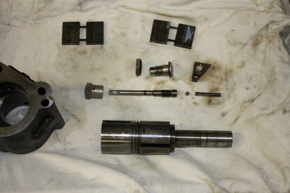
1. The rotor just slides out, towards the input shaft end, letting the 1st stage blades fall out (while holding them to avoid 'sproing tinkle tinkle'.) Here the 1st stage blades are put back in the rotor in original orientation.
2. Both blade sets removed.
3. For orientation of the ballast valve retainer.
4. Showing ballast valve ball and spring.
5. Cleaning the pump body. Inlet attachment at top left, outlet holes at right, ballast air valve hole at center, still with the original rubber seal at bottom of the hole.
At this point things to be done were:
- Decide on the length I wanted for new belts, and find a source for them.
- Find a replacement for the small ballbearing from the gas ballast inlet valve. The old one was a bit rusty, and how do you polish a 4.7mm steel ball? Also the new one could be stainless steel.
- Find suitable material to make the two main casing gaskets. The old ones were a red fiber sheet, about 1.5mm uncompressed, 0.9mm compressed. Obviously have to be oil resistant. However the design of the pump allows for some variation in the gasket thickness, so that wasn't critical. Also, all the gaskets are only exposed to the outlet side of the pump, ie not to high vacuum. So outgassing rate should not be a critical problem.
- Research what sort of rubber the various seals were made of, and find a source of suitable sheets of it.
- Research what sort of solvent (that I can get cheaply in bulk) is suitable for final rinse of the pump parts before reassembly. Everything I read on servicing rotary vacuum pumps insists "do not use volatile solvents!" For the obvious reason that a tiny amount of liquid solvent in the pump will go on producing vapour for a long, long time, thus severely worsening the ultimate vacuum reachable with the pump.
I've been cleaning the worst of the muck from the pump using kerosene, but I know that's terrible and the parts will have to be very carefully cleaned in something else next. But what? Non-poisonous and cheap would be good. - Finally there's the question of new vacuum pump oil. I have an assortment of types, just need to check which are suitable. For final assembly the parts should be freshly rinsed, coated with new oil, and assembled dust and fingerprint free.
The old belts are 'Olympic Trojan M-32'. Which means "M section", and 32".
What I wanted was belts 25" to 26" long, same section. They are 10mm across the top, 6.0mm deep, and 6.5mm across the bottom.
First attempt was via Repco, but I discovered their belts range is all for cars, and thus virtually all flat and/or toothed belts. None that suited the pulleys on the pump. However they did have gasket sheets that should do for the pump body seals. "Payen RM025 Tempflex 456 0.8mm" It's actually 1.0mm uncompressed. See how it goes.
A bit of googling and phoning came up with BSC bearings and power transmission, Moorebank. They had the perfect belts; 26" M-section, that fit just like the old ones. They also turned out to stock ball bearings, including the exact ones I wanted. 4.7mm stainless.
So that ticked off the first three items, leaving the rubber seals, and solvent.
 Meanwhile a book I'd ordered a while ago arrived. 'Modern Vaccum Practice' by Nigel Harris.
'Modern', in the sense that it cost $6 incl post, due to being a 1989 edition, ha ha.
Anyway, it mentions nitrile rubber as having low outgassing, good deformation resistance, and oil resistance. Next higher material for even lower outgassing and moderate bakeability is fluoroelastomer.
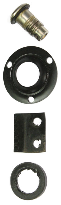
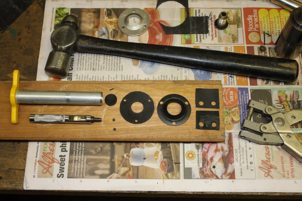
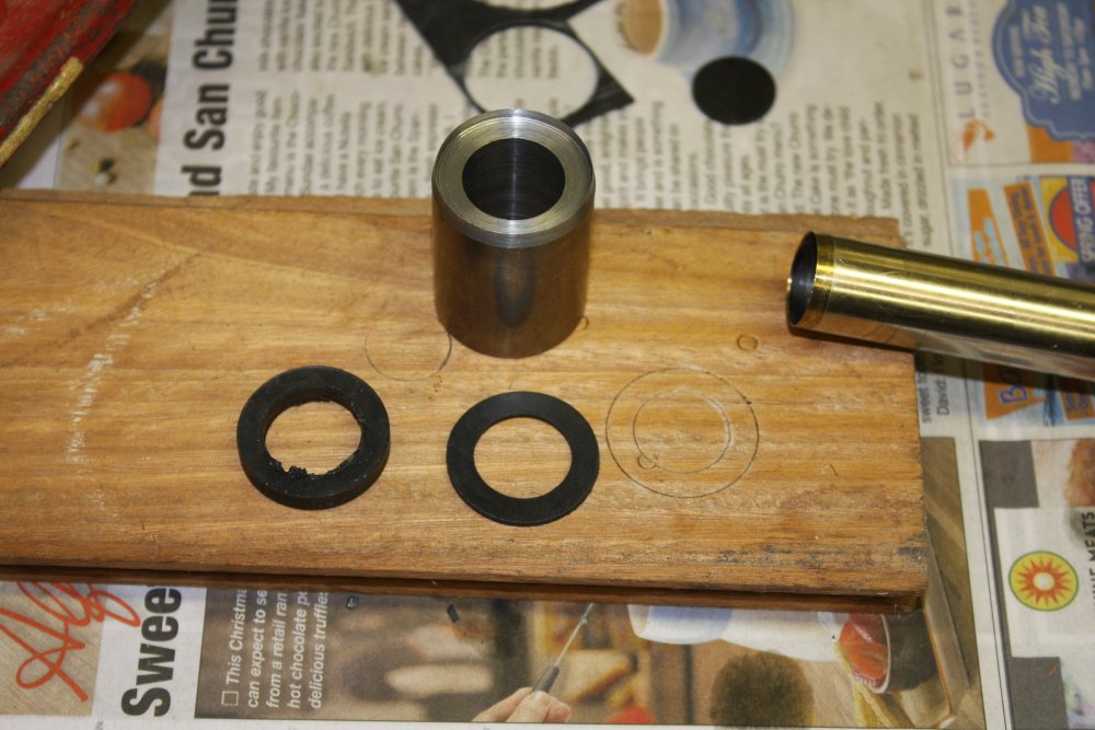
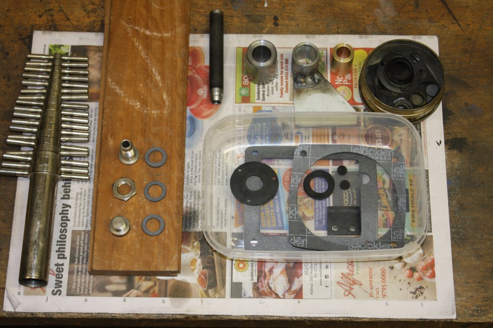
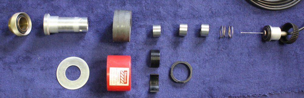
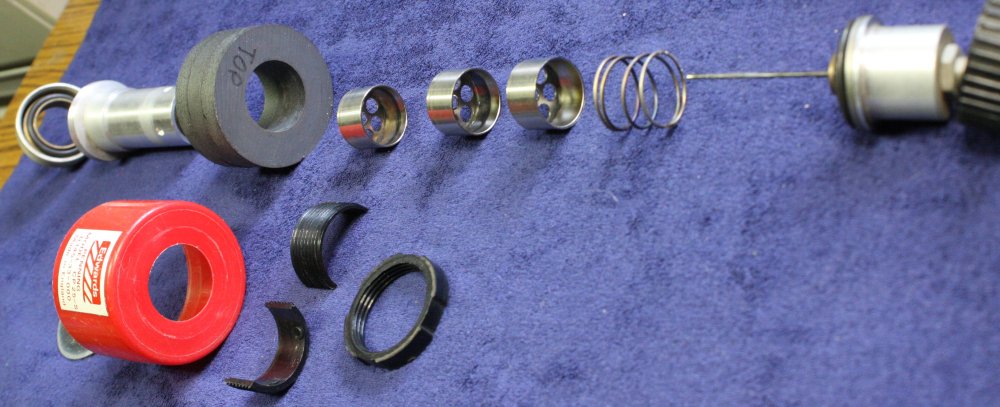
Of all those seals, only one is not 1.6mm thick. That's the bottom one at right. It is the case seal around the inlet port tube, and is 4.4mm thick. Of all the seals it's the least critical, since it has atmospheric pressure on both sides, and isn't preventing oil from escaping. It's just large because it has to adapt to alignment changes due to the main case fibre gasket thickness variations.
The one at top on the metal piece is equally non-critical. There's also a small O-ring inside that piece, but I can't get it out without damaging it. It too is non-critical and I will probably leave it.
The ones that matter are the middle two. The round one is the main shaft oil seal. If it leaks, oil escapes.
The square one is the pump 2nd stage outlet flap valve. It needs to stay flexible while immersed in oil.
Googling for nitrile rubber sheet turned up TotalRubber.com.au. Their online catalog lists nitrile rubbre sheet, including 1.6mm thick. Their price list gives a reasonable price for 10m rolls. I don't mind buying a lot, as I'm likely to use a lot of this stuff for general seals in the vacuum system. They are more than 40 minutes drive away and I was about to head over there when I thought 'better check by phone first.' Sigh. Lucky I did. They say "No, haven't stocked that for years, no we won't import it any more."
Well that's great guys, what about updating your online info? I asked them if they knew who might stock it.
Was given a name of a place that's about 2 minutes drive away, and I've even noticed it when driving past it often. Cool! Associated Gaskets, Revesby. agaus.com.au
I phone, yes they have it in stock. It was Friday afternoon, they weren't sure they'd be able to cut me some today. I went there anyway.
Wow. I've been driving past them for years, never would have guessed they stock a huge range of stuff including lots of electronics related materials. Insulating and conductive tapes, spacers, etc. Anyway they were very helpful, and I now have a big sheet of 1.6mm Nitrile rubber. Interestingly it's about 1.6mm thick in the middle, but at the edges is 1.1mm. This was as much a surprise to the person who served me as to me. Apparently it's standard for the manufacturing process.
Even better they also stock a fluoroelastomer called Viton-A, in various sheet sizes. Something to keep in mind for the future.
20151129 Sunday — Gaskets Day
Well, I have the materials, better get to making the needed gaskets and seals. Some of them were going to require tricks to get them neat.
 |
 |
 |
 |
 |
1. The two large ones were easy — just place the pump case flat on the gasket sheet, mark the shape with pencil (and tidy up with compass and ruler), then cut with scissors and modelling knife. Very conveniently a ring binder hole punch was exactly the right size for the bolt holes.
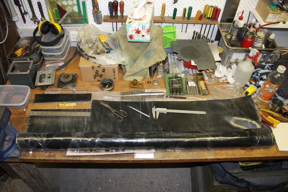
2. Next the Nitrile rubber. This roll is one meter by 1220mm, that cost $50. For this job I only need a small piece, less than the bit I've cut off here. The big roll will get stored away, while the remainder of the small piece will be my workshop stock.
3. Oddly enough the two most critical seals were the easiest to make.
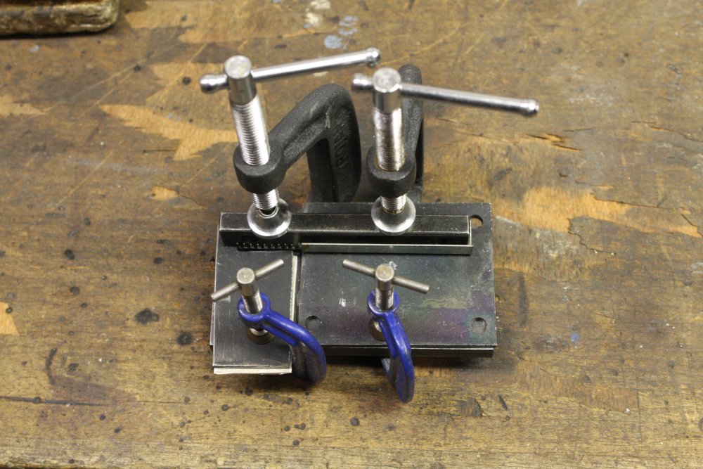
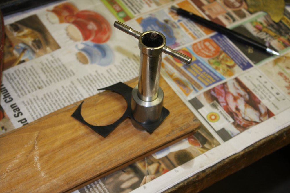
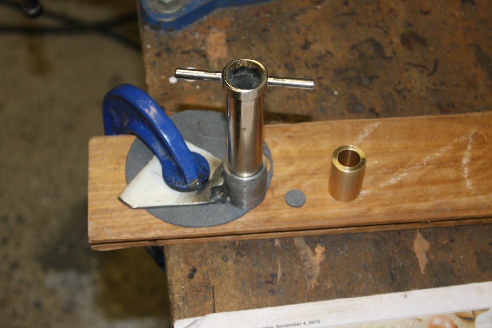
4. While the simplest was nearly the most difficult. That thick rubber washer, will have to be made of three thin identical washers. Making them identical... for this I need a special tool. Something to cut the inner and outer edges of the washer, exactly concentric and neat. I have a set of cork-borers, and one of them was the right size for the inner hole. So this piece of metal is being machined to cut the outer edge, and hold the cork borer centered for the inner edge.
5. Cutting the first one. I'd pulled the scrap sheet up to verify it was cut through all the way round.
 |
 |
 |
 |
 |
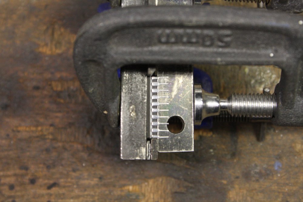
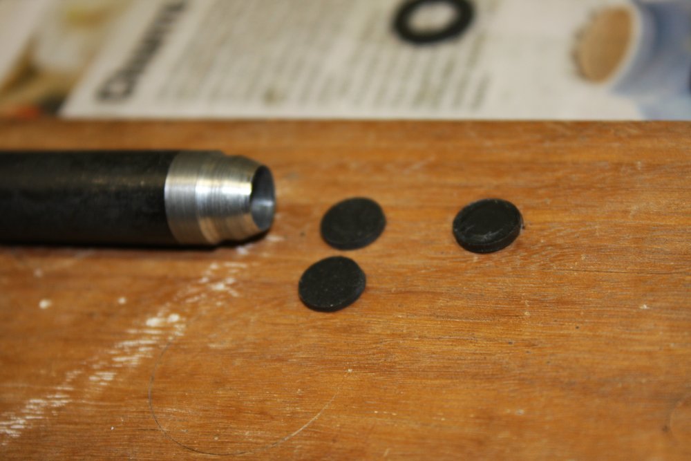
1. Then cutting the inner hole, twisting the sharpish cork borer to cut the rubber sheet. Not much pressure required.
2. First one cut, comparing to the old washer. Need to do two more to pack it up to the old one's thickness.
3. The ballast gas valve has one small round seal. Unfortunately it's 9.5mm in diameter; different to any of my punches and borers. So I had to make a custom punch.
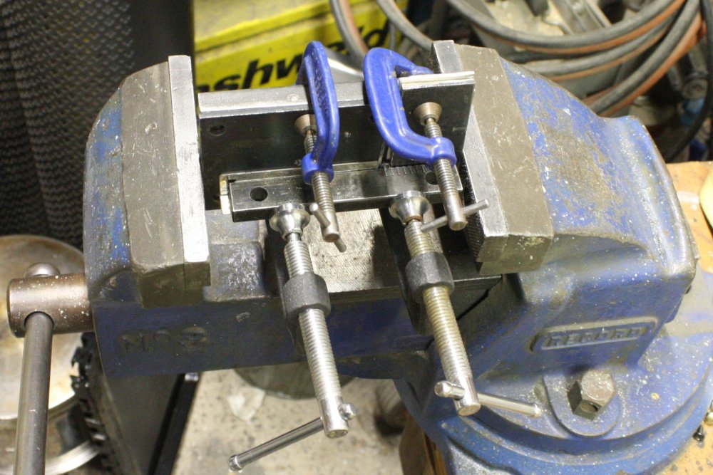
4. For a drain plug and the gas balast valve stem seal, I need three identical washers. Ideally these would be fiber (for the drain plug), and cork for the ballast valve stem seals. Now they're all going to be made of the gasket sheet. Here I'm making a sleeve that can be clamped in position on the sheet material, to hold a cork borer in position.
5. Progressing with those washers. I'd also machined a brass sleeve to hold the smaller cork borer in place. For each washer I'd cut the inner hole first.
 |
 |
1. Then cut the outer edge.
2. That's all of them done.
I still don't have a suitable solvent for rinsing the pump parts just before reassembly.
20151201 Tuesday
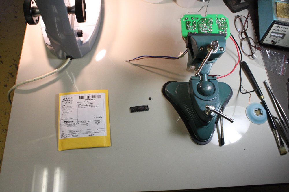
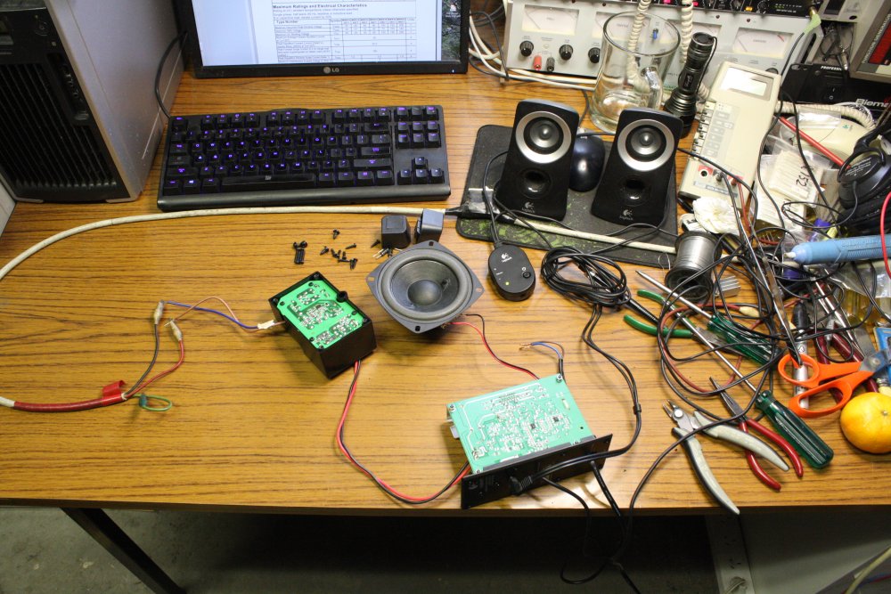
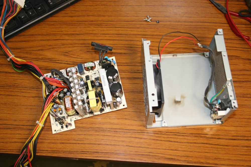
Back on Nov 6th my daughter's audio amp and speakers set for her laptop died. A Logitech Speaker system Z313. I'd taken it apart, found the power supply failed.
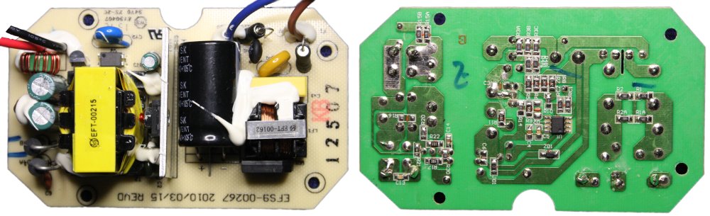
Had a look at that with a scope and the switching regulator control IC appeared to be completely comatose. Not even trying to start so far as I could see. Fetched a datasheet from the net - it's a SanKen SSC620D "PWM, Low EMI, Auto Standby Low Power Off-line SMPS Primary Switcher."
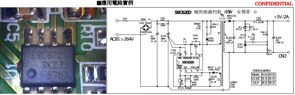
Amusing to see the reference circuit given in the published datasheet is marked 'confidential.' Good thing it isn't on the net then. The actual circuit in Logitech's supply is close enough to the reference that it made sense. The chips are available via AliExpress, US$5.25 for 5. I ordered them. Packed the stereo parts away in a box to await China Post doing their thing slowly but free.
 They arrived on Monday, so fixing this was first on today's list.
Apart from cleaning my keyboard, screen and desk after this slight case of 'oops, can't swallow via the windpipe' while eating breakfast.
Mind: "No no, wait, I can deal with this, just give me a moment."
Lungs: "Nope. I insist. Right now."
Oh well, the keyboard needed a clean anyway. Vacuum cleaner and then scrubbing with a damp stiff bristle brush.
Great start. After finishing the now soggy cereal I dug out the box with the amp parts.
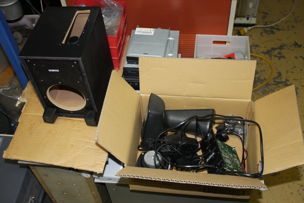 |
I'm wondering what spectacular failure can top that breakfast.
 |
 |
 |
 |
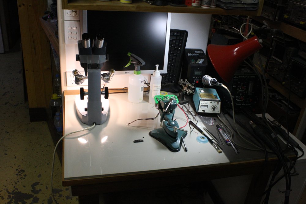
1-2. Another nice result of tidying - my soldering bench is usable again. It had been buried for a while.
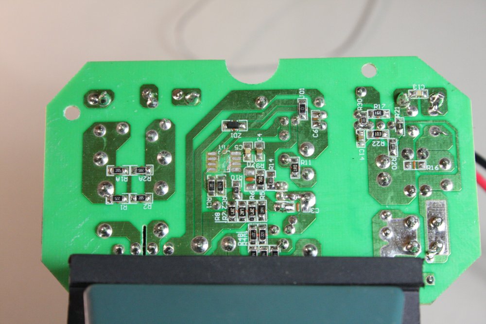
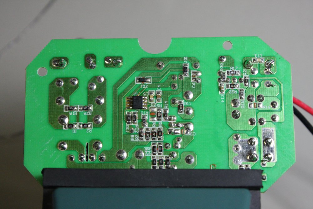
3-4. Suspect IC off, new IC on. Annnnd.... No change. Terrific.
 |
 |
 |
 |
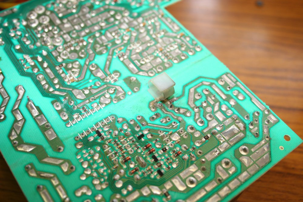
On further checking (what I should have done a month ago), one of the two big output side diodes is a dead short. Interestingly those two diodes are not for anti-phase output windings. They are in parallel... which is generally considered a no-no, since diodes don't tend to share current equally. Hmm...
They are both SB5100, which is a 5A schottky with Vf @ 5A = 0.8V.
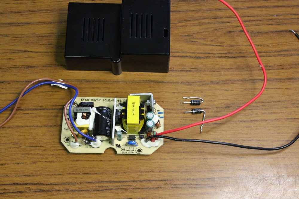
Darn it, I can't find my box of 'mixed big salvaged diodes'. But I do have to go out to very near Jaycar anyway today, so checked their catalog. Closest I found was a dual power schottky in TO220 pack: MBR20100CT. Couple of dollars. Went to do the shopping then rather than after, and replaced both diodes with the MBR20100CT. Also added a small heatsink on it. (pic #1)
Pic 2: Sound testing. It works. Running speakers, diode doesn't seem to get warm.
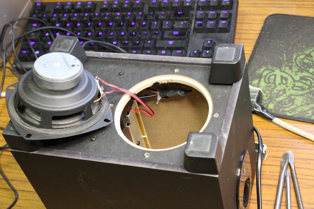
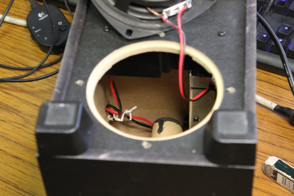
3-4: Reassembling. This case design is extremely awkward. Getting the pieces inside and wires connected is a bit like keyhole surgery. Also because it's a speaker all the wires have to be carefully positioned and secured (with hotmelt glue in one place) to ensure they don't vibrate and rattle.
Ffff! Done.
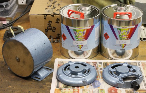 Other things bought: some acetone and isopropyl alcohol (for vacuum system cleaning) and a cable entry clamp for the motor.
20151202 Wednesday
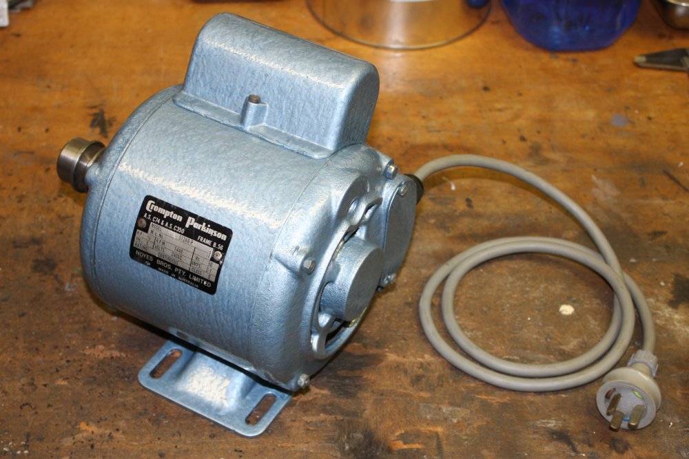
 Started by putting the pump motor back together.
 Ha ha... except I'd forgotten to paint the cover for the starter capacitor, and the terminals block cover. This hammer-tone paint takes a good two days to dry enough to recoat, and it needs two coats.
Actually I didn't 'forget' them, just hadn't been able to decide what to do with them. The cap-cover is plastic, and I wasn't sure this paint would work on it. And the terminal cover has the connections instructions on a label inside, but both sides are a bit rusty and need cleaning and painting. The label won't peel off intact...
The cap-cover I just sanded rough (leaving most of the original paint.) We'll see how the hammer-tone stuff goes.
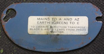 For the cover plate I took a good hi-res photo of the label then just scraped it off. I'll print a new one.
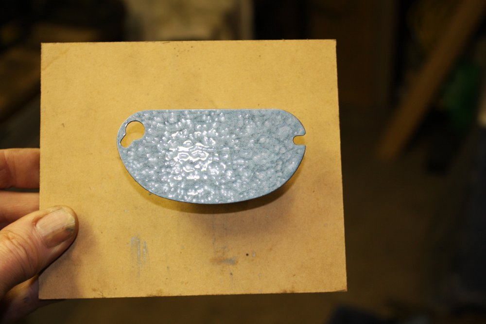
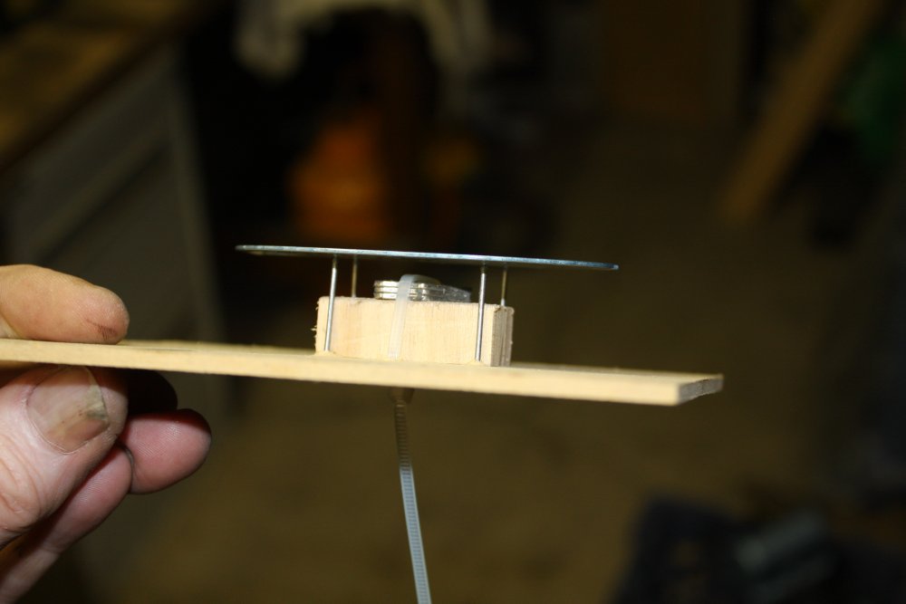
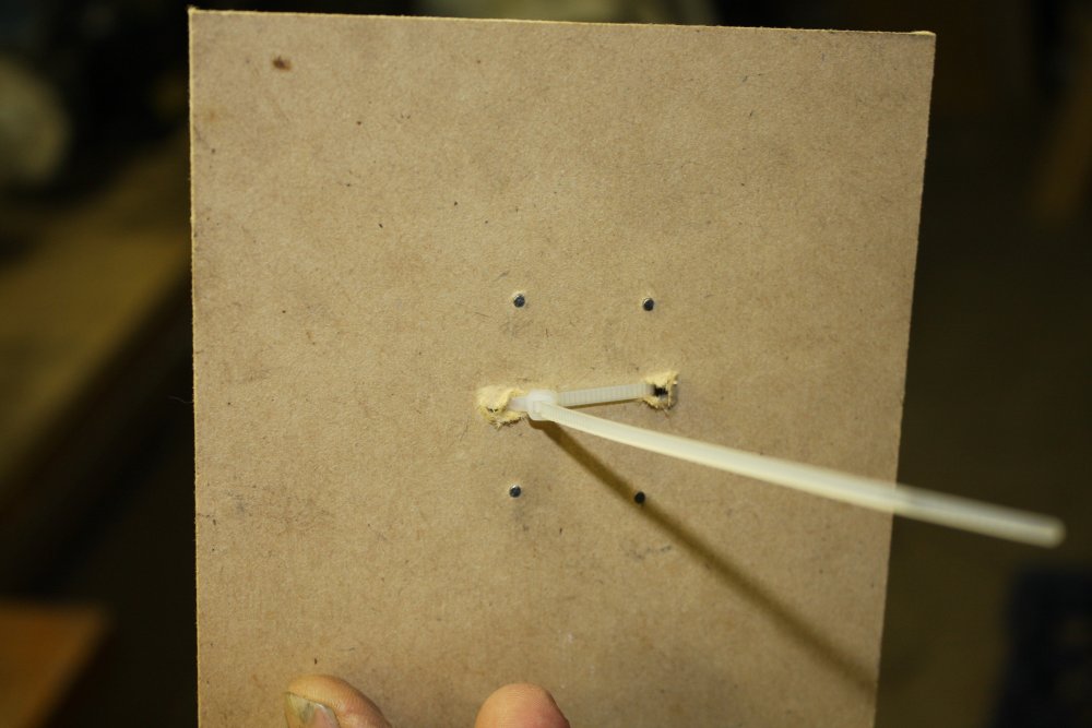
Next problem - how do you brush-paint a small metal part like that terminal cover, holding it still despite the brush strokes, without touching it?
Would be good if one could levitate it somehow.
Like this.
 |
 |
 |
 |
Some scrap wood, small nails, magnets salvaged from old hard disks, and a nylon cable tie. The magnet pulls the metal part onto the nail points, without touching it.
Pic 4: The motor completed.
The Repair That Never Was
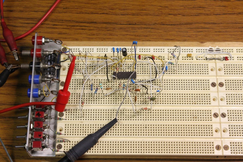
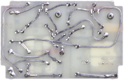
Bah.My little Bransonic ultrasonic cleaner bath has been sitting on a shelf disassembled, 'waiting for repair' for several years. Too many other distractions, and it's in a queue of many other things to fix. Also I had no schematic, and despite the simplicity of the circuit that was enough to put me off trying to fix it.
It's too small to deal with the larger pump parts, but some of the small parts will fit. Besides, just the idea of cleaning the pump reminds me about the broken ultrasonic cleaner. During this ongoing tidy up, I'd put it in a line of things near my desk, that I want to fix soon.
So today I finally got to it.
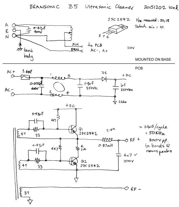
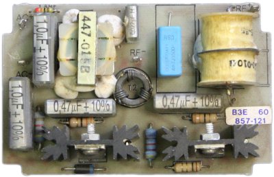
The schematic drawing is rough as it's a first draft. Rare to trace a circuit so small I can guess the overall layout well enough from the start to not need to redraw it a few times as the structure becomes clear.
All I remember about why I took it apart was 'didn't go', but I'm pretty sure I looked with a scope, checking that there was no signal.
This time I set up properly. Variac and isolation transformer, then started through that mental checklist:
The base:
- Input transformer, both windings are OK.
- With mains applied to xformer, get half mains voltage out, as expected. (Not connected to PCB.)
The piezo:
Too lazy to rig up some signal generator able to produce HV output, I just stuck my fingers across the piezo terminals as a crude pulldown resistor. And now it works... each touch with 30V makes a clearly audible click in the tank. Can't even feel the 30V across my fingertips.
I can only recall ever using myself to emulate resistors and capacitors while debugging. Someday I want to be an inductor. :)
The PCB:
- Multimeter says the fuse is OK.
- Multimeter check D1 - OK.
- Downloaded datasheet for Q1 & Q2. Pulled both of them out of the board.
- Diode check B-E, B-C junctions and C-E open... all OK.
- Check Q1 & Q2 gain in a transistor tester: measured 20 and 18. Datasheet says min = 10, so OK.
- Check all the 4K7 and 33 ohm resistors - OK.
- The output inductor is not open circuit.
- Lift one leg of the 4n7 output resonator cap, measure the inductor and that cap. Values seem good.
- Close visual check under magnifier of all solder joints. Not a sausage.
Hmm.... I've run out of things on my list. OK, so scope time. I solder a scope ground point onto the 'zero' trace, solder the transistors and the lead of the resonator cap back in. Recheck I'm really supplying power through the isolation transformer. Put the scope probe on the +DC rail.
Turn the mains on, start winding up the mains voltage with the variac.
Nothing but half-wave rectified ripple on the supply rail. But it does say the whole supply chain is working. Also that the transistor pair is drawing current, since otherwise the +DC filter cap would charge to peak and stay there.
Shut it down, and connect the the piezo to the RF+, RF- terminals. The oscillator uses the piezo for feedback, so is not going to do anything without it.
This time, with the scope probe on the RF+ output, as soon as the mains supply is wound up to near operating voltage, the thing bursts into life. I can hear it as well as see bursts on the scope. But it's pretty weak looking....
Mmm... feedback, from the piezo... does it matter whether there is fluid in the tank?
I add some water. Immediately the oscillation bursts get much more powerful, and the audible noise increases. The surface of the water has vibration patterns and sometimes throws drops of water into the air.

Yay, it's working. But I have no idea why it wasn't before.
 Experimenting, I find that it tends not to run if the mains voltage is much below nominal. And of course it won't ever do anything if the piezo isn't connected. But I didn't know that before I traced the schematic.
So I wonder. Did it not run because the mains was a bit low one day and I started with the tank empty? And when I took it apart to have a quick look for a fault, did I only try it without the piezo connected?
Ha ha. Sometimes I'm such an idiot. Apparently I've had this thing sitting in pieces for years, for no good reason. Dammit.
More Music
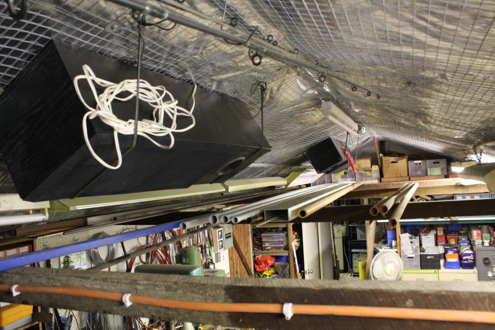
The area I live has fairly large land allotment sizes. People with large yards tend to keep dogs. Around here, several of them keep multiple dogs, in kennels. One guy races grayhounds, another person seems to breed dogs. Many, small yappy dogs. There are also random other dogs in nearby yards. They like to bark at each other. Also since October there's been a rockhammer excavating down through bedrock in a diagonally adjacent lot. So it gets pretty noisy sometimes. As a result I often have music playing in my main lab to drown out the nuisance noise to the point where I can think.
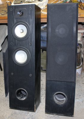
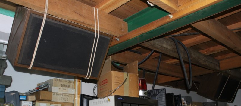 Floor space here is in short supply, so the speakers are hung from the ceiling with rope. Meh, I don't care about appearance, so long as it works.
The chipboard around the bases has swollen due to damp,
but who cares.
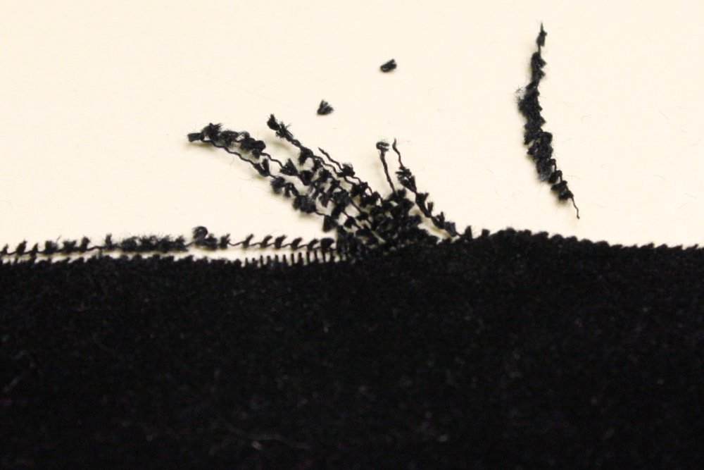
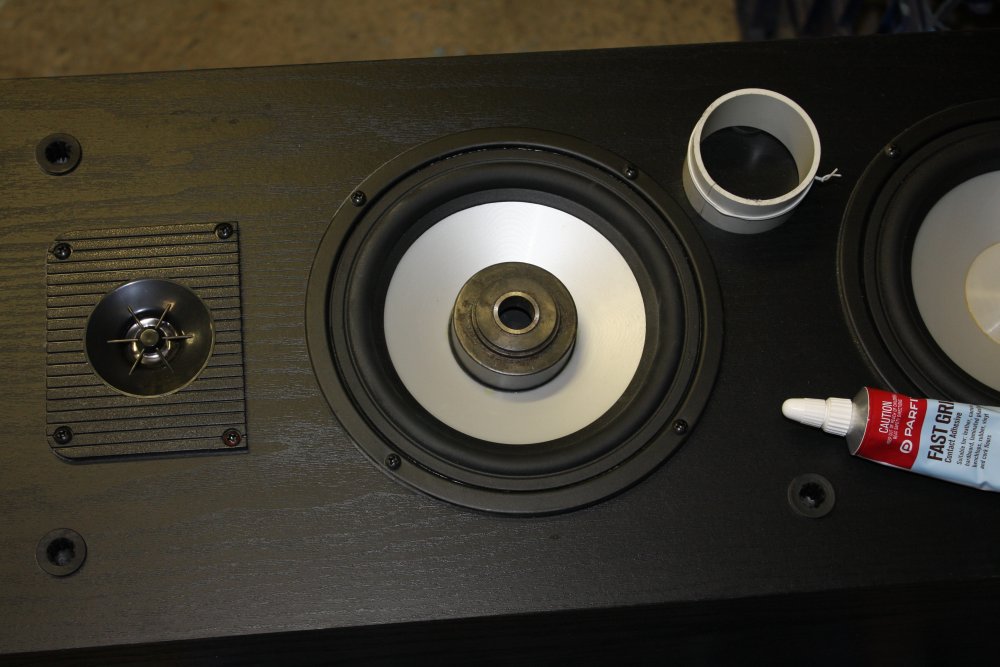
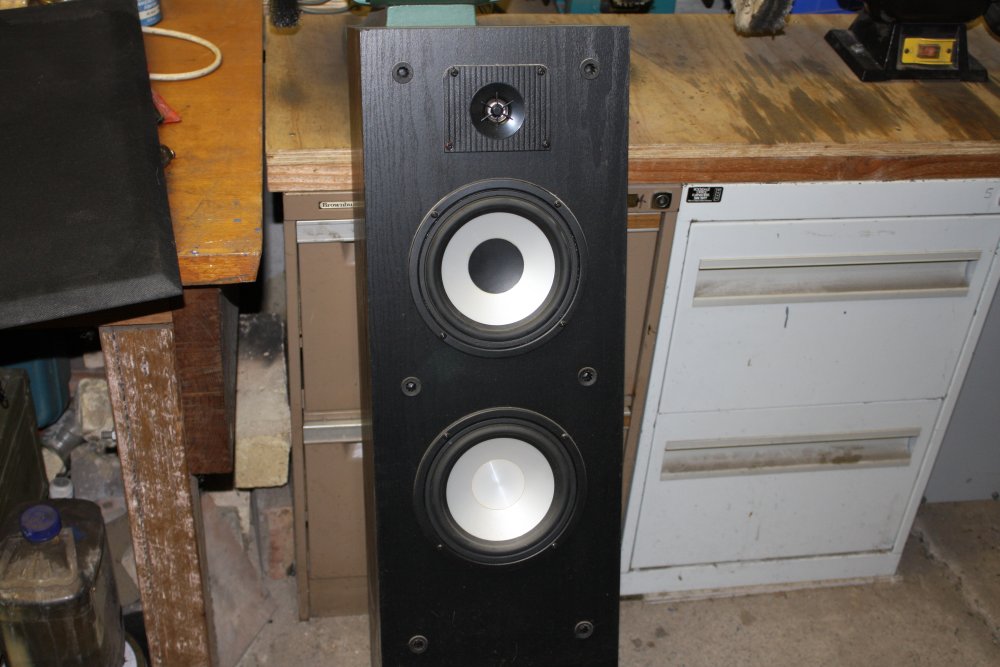
On one of the speaker cones the middle cover has fallen off,
and that needs fixing.
Otherwise dust and iron filings will get into the magnet gap.
Recently I found a suitable pair, street tossed:
 A few weeks ago I fixed a speaker for a friend, replacing the damaged woofer. Peeling the central domed disk off that broken one, I cut it down to the size needed for this speaker.
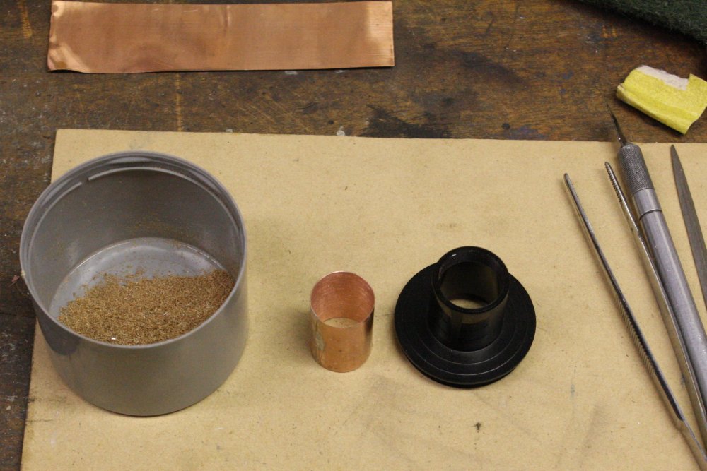
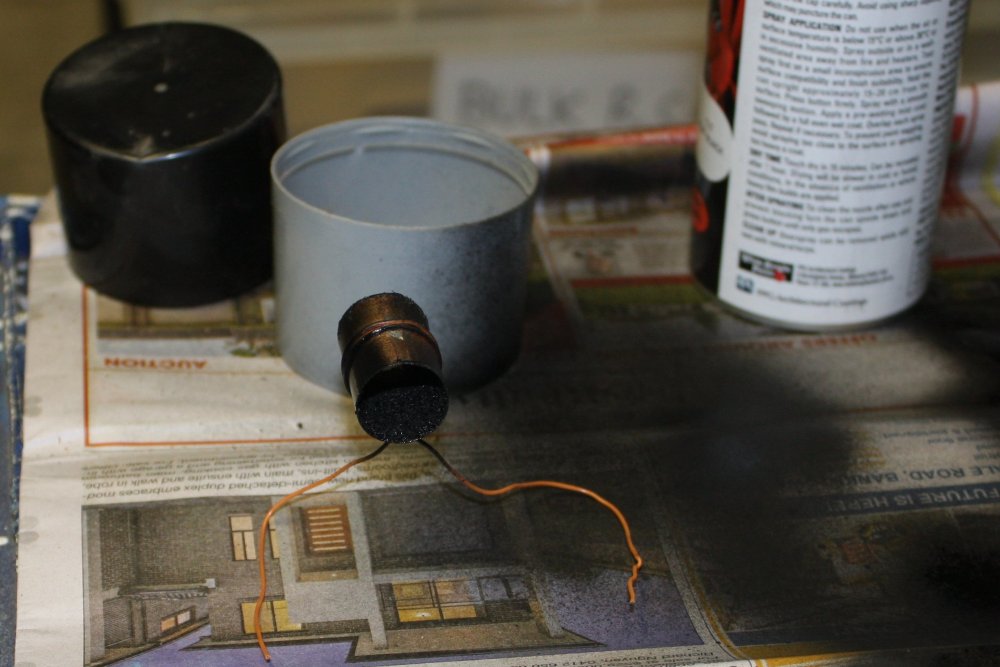
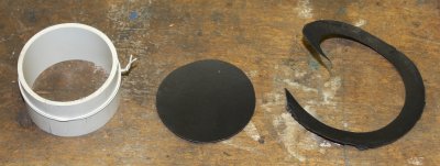
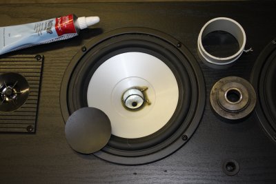 Preparing to glue it in.
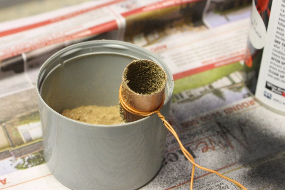
I'd found a metal weight just the right size, after having made that correct-size tube I'd intended to use to keep the edge glue joint under pressure.
It's a piece of PVC pipe, with a slit cut along one side so when the slit is held closed, the tube becomes the desired diameter.
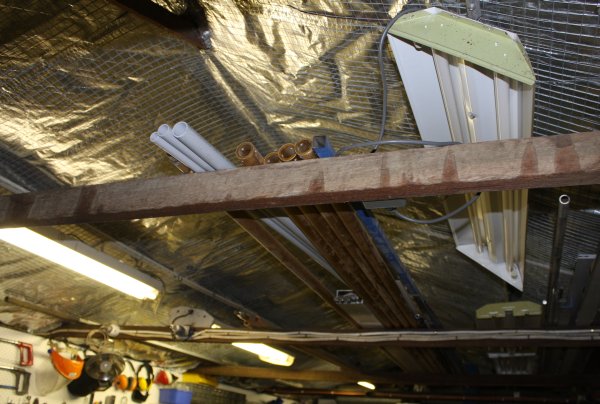
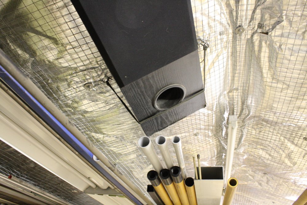
After gluing, for a while I dithered over how best to suspend them. Ease of actually getting them up there, and moving them in future is the number one requirement. So for a while I dithered. Ended up screwing some 'wire eye straps' onto the beams, and using cord. This allows starting with large loops, resting the speakers in the loops, then tightening the cord.
 |
 |
 |
 |
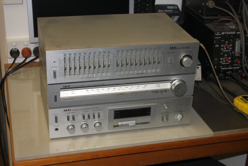 |
Still not sure what I'll use for an amp. Pic 5 is an old system I had lying around. But it's so big, and I don't want to waste that much bench space. Also it has a few faults that need fixing, but they should be easy. I guess I'll use it temporarily, till I find something smaller.
Also needed are some audio and other LV wiring between the mech workshop and the main lab, where the media server is. Another job.
Back to Vacuum
During this cleanup I'm trying to gather together all the assorted bits of vacuum-related gear I have, prior to doing more work on my vacuum chamber system. Years ago I was given a mix of quite old bits and pieces along with the very nice things: the big chamber, some good vacuum roughing pumps, a few oil diffusion pumps, etc.That stuff all got stored during the house and workshops building saga. Most of it in the old fibro garage that's now my mech workshop. That old, very basic building suffered several termite attacks over the years. Sometimes the termites would reach stored equipment before I found them. They eat wood, but they also like to colonize narrow spaces between any kind of non-wooden objects. There was one box containing several vacuum gauge controlers that this happened to. Termites build with woodpulp, mud and their spit. The result is corrosive to metal. At the time I did very minimal cleaning of the gear; just scraped the worst off and stored it again.
Now I'll pay for that.
 |
 |
 |
 |
 |
1. Washing the termite gunk off. With the cast alloy cases that was all they required. But the steel cases had rusted under the paint.
2. With the steel ones I stripped all the affected areas back to metal, then repainted. More of that blue hammertone, I like it. Plus I had the tin on the bench and a brush wet with it.
3 - 4. This one is for a cold cathode vacuum sensor, that I have several of. (Could be wrong.)
5. Nice looking again. Whether it can be got working remains to be seen.
 |
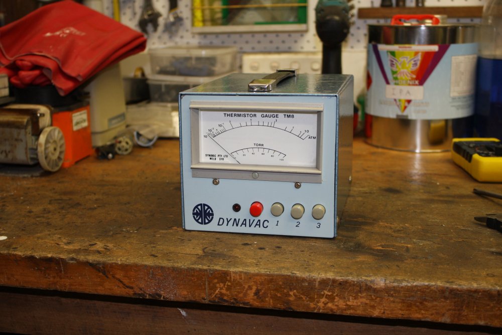 |
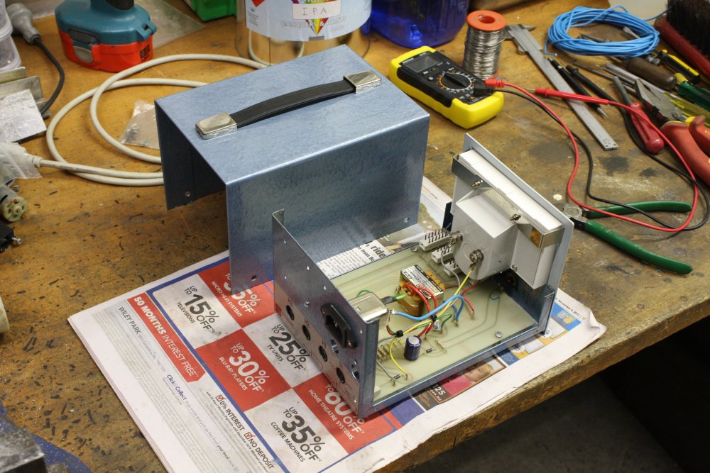
1 - 2. A thermistor vacuum gauge controler. Pretty sure I don't have the sensors to match this, but I restored it anyway in case I find some. It and its sensors were supposed to be included with my Varian Helium Leak Detector system when I won it in an auction. But when picking it up, someone had already swiped the sensors. It's not part of the leak detector.
The IEC mains cord socket is my mod; originally it had a clamped mains cord.
There's amazingly little to this thing.
Vacuum Systems Cleanliness is HARD
As for reassembling the vacuum pump, it's been surprisingly difficult to prepare everything needed.
This little, old pump, that I'm only going to use for random jobs unrelated to the main vacuum setup, really isn't critical. Probably any minimal cleaning would do for reassembly. But I'm going to try to treat it with care, as a learning exercise and practice for working on more critical pumps later. There doesn't seem to be much online on the required techniques, but here's one:
CLEANING FOR VACUUM SERVICE - http://vacuumcursus.nl/casussen/Cleaning_Chapter.pdf.
For this rotary oil pump I'll only attempt a fairly low grade method. In outline the proceedure sounds simple: wash parts in isopropyl alcohol (IPA), dry, coat with clean vacuum oil before reassembling close-fitting parts together.
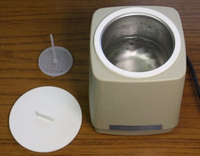
But there are a few difficulties. Just for starters, how do you 'wash in IPA'? The stuff evaporates like crazy, the fumes are flammable, and the parts are quite large. I'll need some big container to use as a tub, holding a fair bit of IPA. But when I'm not actually holding a part in there and scrubbing or squirting IPA over it, the tub needs a cover to minimize evaporation.
I found a large stainless cooking pot, with a metal-rimmed glass lid that fits fairly well. It will do to keep dust out, but it won't seal IPA fumes in. I clean it carefully, double rinse with distillled water, air dry upside down.
Then there's gloves. Something to avoid getting IPA on skin or fingerprints on the pump parts. Normally no problem — I'd use a pair of those red rubber chemical resistant gloves. But I don't know if those gloves leave residues, ie should not be allowed to touch the pump surfaces after cleaning. This I have to find out.
And 'scrubbing' - with what? Leaving lint is probably not OK. Nor are scratches on the pump surfaces. Sponges might leave residues. More questions.
The IPA will be picking up old pump oil from the parts. How do I know when it's time to switch to new IPA?
Also storing the used IPA, if it's good enough to use again for vacuum system cleaning... I can't keep it in the unsealed tub. I can put it in a sealed container... and that has to be clean. A big glass jar with airtight lid, well washed, double rinsed with distilled water, then air dried upside down, provides that. But all my workshop funnels are dirty and oily. I find a big pyrex funnel, wash it, and put in a clean plastic bag for later.
'Drying' is supposed to be with clean, dry, oil-free compressed air. No can do, my old compressor does not have any filtering on the air line. Also of course all the existing hose and air nozzle would count as hopelessly contaminated with oil and dust.
It's surprising, but I haven't yet been able to find an active discussion forum specializing in vacuum systems techniques.
20151209 Meanwhile, Cat and Storm
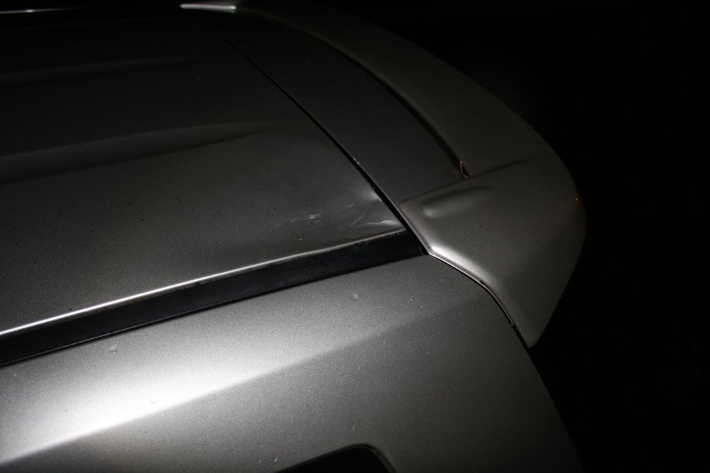
Reassembling that pump is turning into one of those 'ohhhh I am not sure how to do this' things. What's a word that combines procrastinating, sidestracked and lack of confidence? Anyway, that. Apart from parallel events...My son has been a mining engineer at a mine in NW Queensland for a few years. He'd commute between Sydney and the mine, one week on, one off. Having become sick of so much flying (and I suppose, living with parents) he's decided to move to Brisbane. He'd be driving his car up from Sydney to Brisbane on 11th December. On the 9th, at dusk there was a wild storm here. Heavy rain, strong winds. A tree out the front lost some branches, and one of them fell on his car.
 |
 |
 |
 |
 |
 |
Wait, what has a cat got to do with that? Well, this is the big stray cat I mentioned previously, now a friend of mine. I'd happened to take some pics of him earlier that day, so included here. Still wondering what I should call him.
Then the storm. The branch didn't do much damage, only a dent in a corner of the roof. It's just bad timing, especially since my son recently decided to not renew the car insurance. On the principle that it's an oldish car and he could easily afford to replace it, I guess. Anyway now I have a bit of tree-lopping rope work added to my chores list, since two branches broke and fell, but another two broke and are still hung up. Way up near the top, in a large, tall tree.
I think I'll call the cat Storm. Either that or Doink.
20151212 Serendipity getting ridiculous
Remember that small label from the motor, that I said "I'll print a new one"?Well, I don't actually have a printer anymore. I so rarely need one, and inkjet printers are a pain, especialy if almost never used. What I meant was "I'll print one at someone else's place, who has a printer." So of course I didn't get round to doing that yet.
On Thursday the 10th I spend most of the day cleaning and polishing furniture, at my mum's place. She's too old to manage such things now. On the drive over I'd spotted a kerbside toss 'office machine'. I've been trying to resist picking up junk since I really don't need any more stepper motors and metal rods, etc. But this was a big, quite new looking thing. Due to being in a hurry I tossed it in the back of the car without paying attention to what it was. I've been hoping to start finding digital copiers containing hard disks, and so grabbed it mainly since 'looks recent, might be one of those.' The front cover was skew and didn't close properly, so I assumed it was a writeoff, good only for teardown for parts and curiosity.
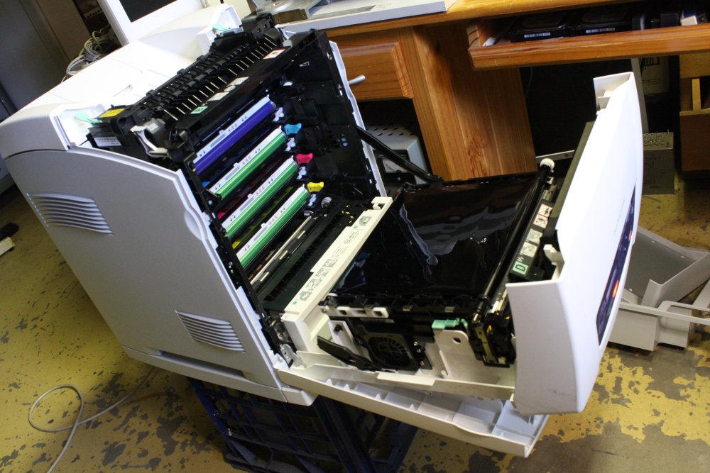
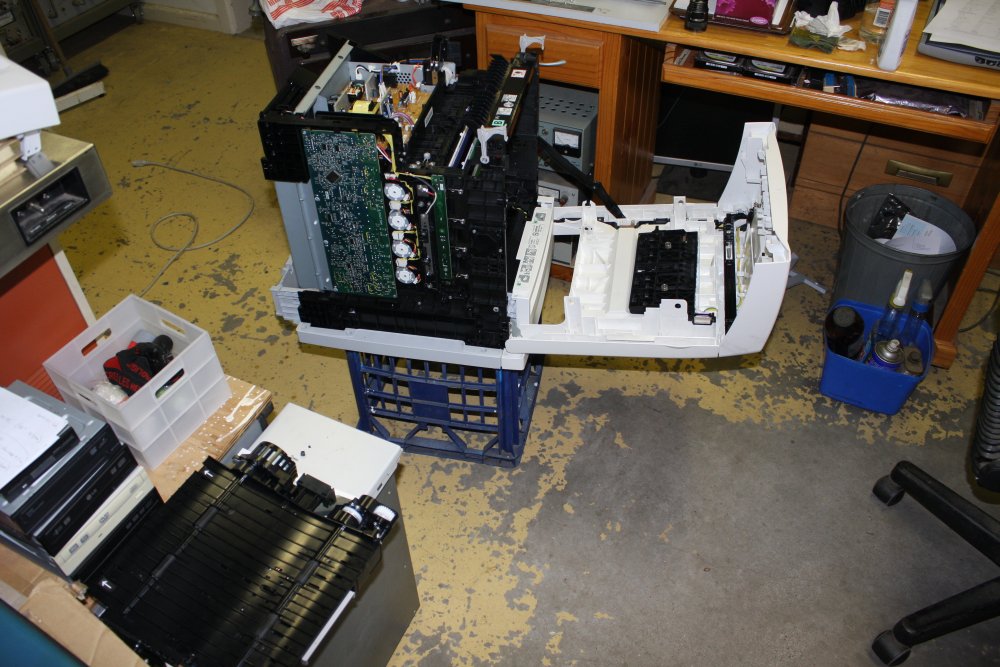
When I got it home and looked, it turned out to be a color laser network printer. A Fuji-Xerox Docuprint C3300 DX, duplex, 30ppm; to quote the brochure: "High-performance colour laser printer for large enterprises". Sitting on the grass in front of a small old house. It had been out in light overnight rain, so had water through some areas inside. It was interesting to see the stack of four separate YMC+Black drum cartridges, and I was very curious to see how the laser system wrote to four drums, not just the usual one in a B&W laser printer. Never pulled a colour laser printer apart before. Being busy just then, I left the covers open for a while to dry it out. It was hot here in Sydney.
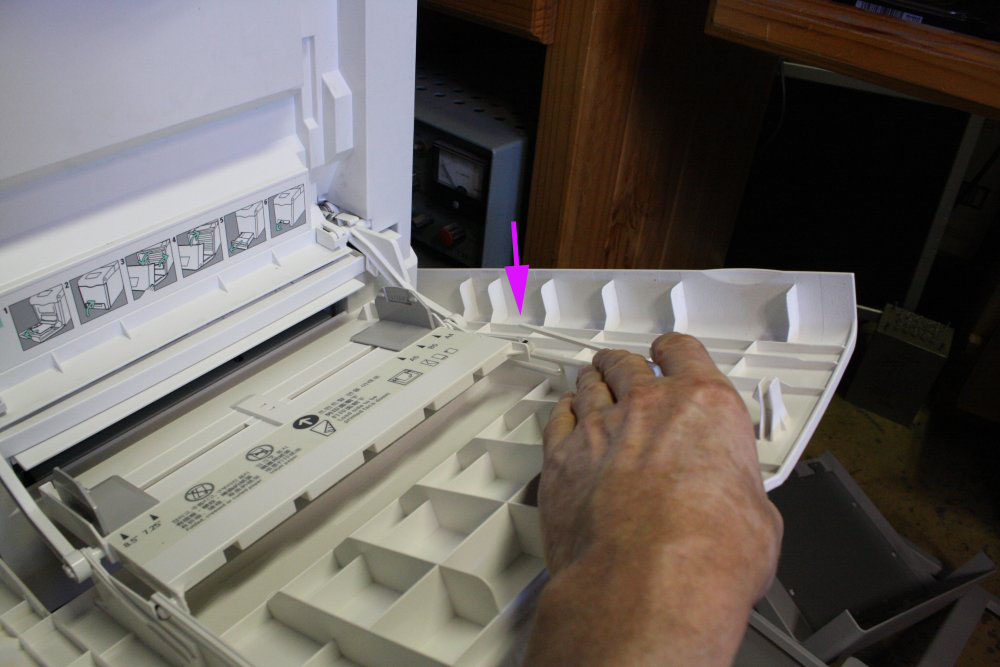
What started to get my attention was realizing the unit had been owned by someone either very heavy handed, or short tempered. A few physical breakages, most apparently from the user slamming body doors open and closed violently, wrenching paper guides, etc. The obvious ones:
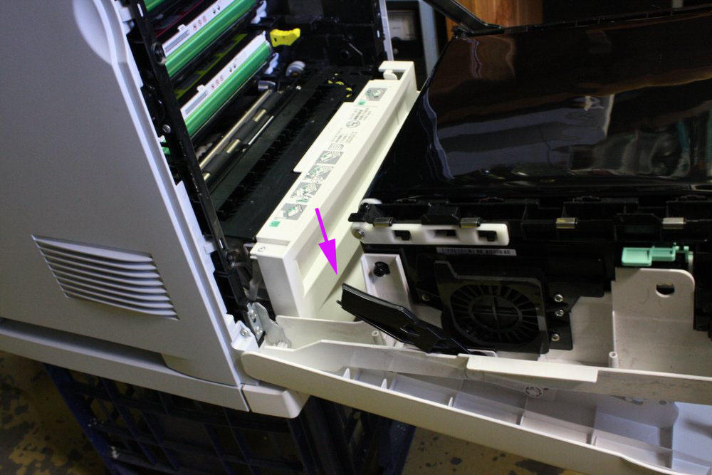
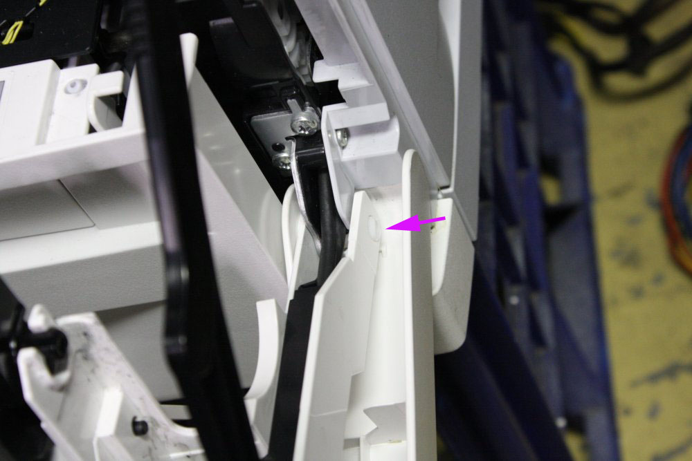
- One hinge on the main front lid. The pin is plastic and an end flange has snapped off, allowing it to pop out of position. Result: no actual hinge. That's why the front door was hanging skew when I found it. This halts the machine since the door doesn't position properly and it carries the main paper feed path. The broken pin was easily slid back into place temporarily, and will stay there long enough for testing.
- Restraining arm and damper on left of main door, snapped right off. Also prevents the door closing cleanly unless you carefully steer the broken end while closing the door. I was hoping the other half would be inside the case, in which case I could join it back together. But no luck there. Anyway this is not critical to operation.
- Plastic gear that equalizes the manual paper feed guides. Had popped off it's pivot and was rattling around loose inside. Just popped it back on.
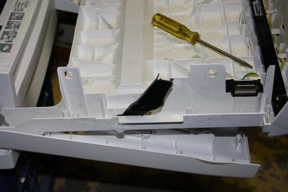
- A snapped thin plastic guide that's part of the manual feed path. Obviously broken by violently opening the front cover. This was easily repaired by gluing.
- Somehow they'd managed to get the bottom of the paper tray all gummed up with clear sticky tape. Not for any reason; it just seemed to have been accidentally stuck there then mangled a bit more each time the tray was inserted. Sticky gunk all over it. Took a while to clean off.
The plan had been to immediately dismantle the machine, not even bother powering on. But what the heck... it looks in good condition otherwise. Very clean, drums seem OK, and the design is clever - all the major modules unclip easily. Just in case those visible broken things are the only faults... I waited a couple of days till it was well dried out then after fixing the critical hinge pin, powered it up.
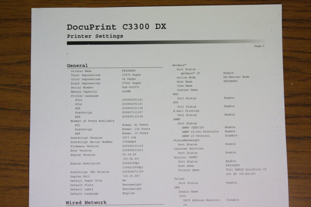
Ha ha... it works. At least it prints a clean B&W page of status and settings.
 So funny to see the page counters:
Meaning, the color cartridges are full. I wonder who bought a very expensive color laser printer, then only used it for bulk B&W printing?
Next: get the manual and drivers and try color printing. The manual was easy, drivers not so much. That's my fault, since I'm a Microsoft Cynic, and refuse to follow them on their perpetual quest to degrade Windows to visually pretty but useless bloated trash, backdoored spying nightmare, and rental-model ransom-ware. I still use XP, and revert later-OS machines to XP when I can. My next OS change will be to something non-Microsoft. Don't like Linux much either. Now, this printer was manufactured in 2009, so there should be WinXP drivers. And they have a WinXP drivers category on their site. But the only XP driver there now is a Korean language version. Sigh...
So now I'm hunting those couple of plastic parts, and the XP drivers.
I don't really care if it works; it's not like I greatly need a color printer, or have space to set it up permanently. But it's amusing to get a very good one for free, and with full color cartridges. Even more amusing that this happens so soon after I'd made a note to myself to print the little replacement label for the wiring details inside the motor cover. I think someone needs to have a private word with Serendipity about her steroids doping problem. Giving me an enterprise-level high volume colour laser printer, when I just need to print one tiny B&W label, is a bit overdoing it don't you think?
Still, I am grateful.
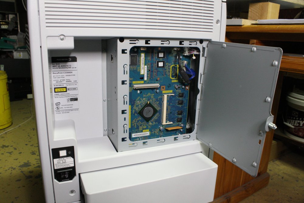
 |
 |
 |
 |
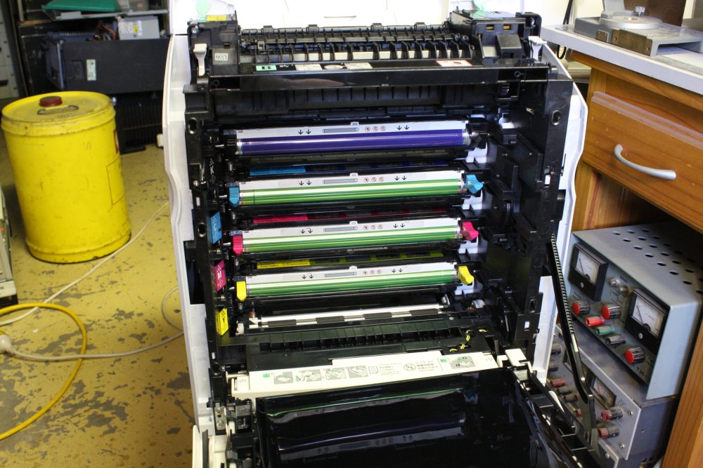 |
1: Snapped rail. 2: Front clamshell open. 3: Snapped clamshell opening restraint arm. 4: Broken hinge pin, sitting in place. Nothing stopping it falling out again. 5: The cartridges, which pull out easily.
 |
 |
 |
 |
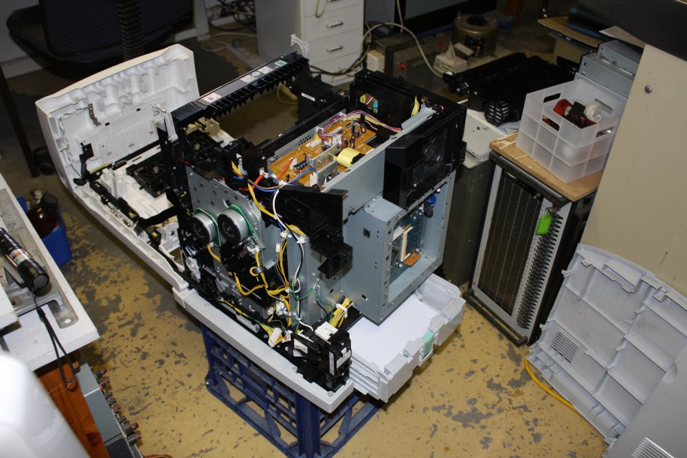 |
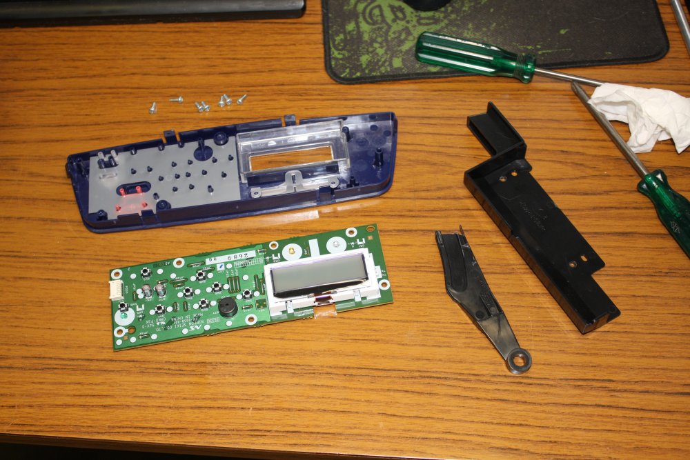
1: First print. 2: Broken arm again. 3: Checking front panel PCB for water damage. It's fine. 4: Stripping it down a bit. It's nicely modular. 5: All the laser optics are in a vertical block underneath that power supply PCB at the top. If the machine was dead, that's where I'd be digging to next. But since it is working... I'll have to wait.
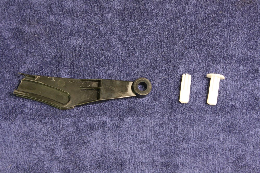 |
 |
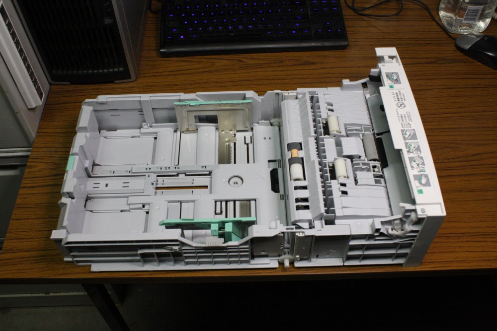 |
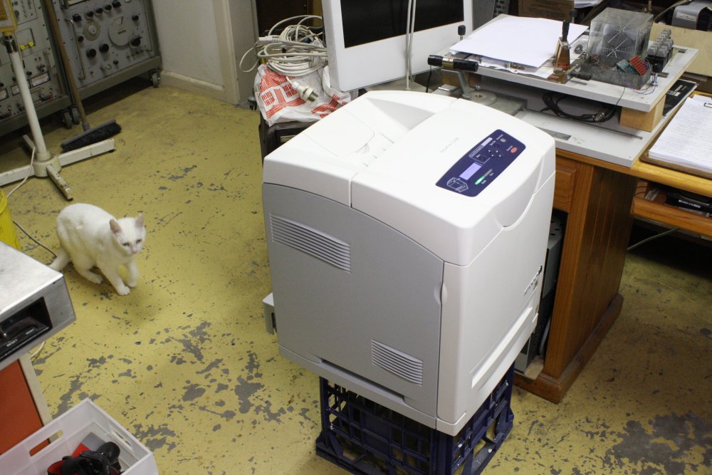 |
1: Broken parts, and an intact pin for comparison. 2: The control PCB at rear. Turns out this printer does have a hard disk option, but it isn't installed. 3: Is this the most complicated paper tray ever? 4: With the panels off, I could wash them in the sink. It cleaned up quite nicely. Pure white cat for comparison.
Later...
Darn it. Turns out Fuji-Xerox are one of those arsehole companies that do not maintain spare parts inventories. Presumably since they would rather your machine just died and you bought a new one. Two separate printer/copier service outlets I tried had no luck getting either the small pin or the ratchet arm.
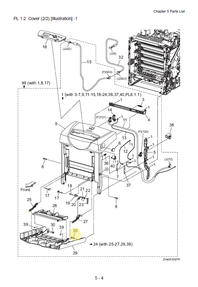 The first place tried, was given this diagram just for the hinge pin (hilighted, #30.)
Fuji-Xerox quoted $172 + GST for it. Turns out they won't supply anything less than that whole front door assembly.
The second place, that specifically advertises as a printer and photocopier repair business, stated outright that most printer/photocopier manufacturers will no longer supply spare parts, and in general spares can only be found by buying 2nd hand machines from ebay and other sources.
I find this situation quite outrageous. If I had anything to do with it, companies selling complex equipment of any kind would be required to make full service manuals available online for free, and also guarantee spare parts would be available at reasonable cost for the expected lifetime of the product. Or else they and their unrepairable planned obsolescence products would be banned from the market.
Anyway, looks like I'll be machining a replacement pin up on my lathe. The ratchet arm... a bit more difficult. For the moment the machine can live without it. But I know what one of the first projects will be for my future 3D printer.
A 3D printer repairing an older 2D printer — ironic.
I did eventually print up that little label for the pump motor.
20151213 Gauging inventory
A vacuum system is useless without an ability to measure the vacuum achieved. That's what vacuum gauges are for. There are many kinds, each with their own quirks and vacuum working range. Since my system is cobbled together from odds and ends (mostly gifts and finds), so will the gauging be. As my sorting through long-stored stuff continues, here's most of what I've found in the way of vacuum measuring gear.
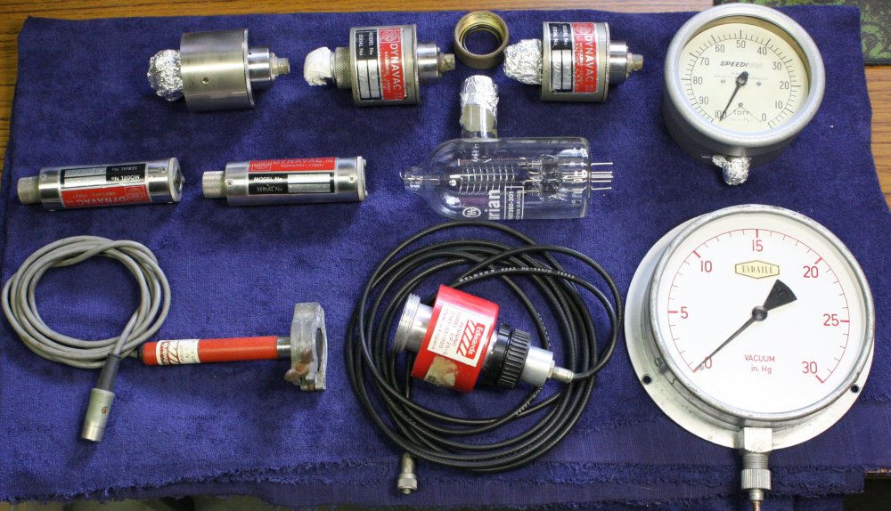
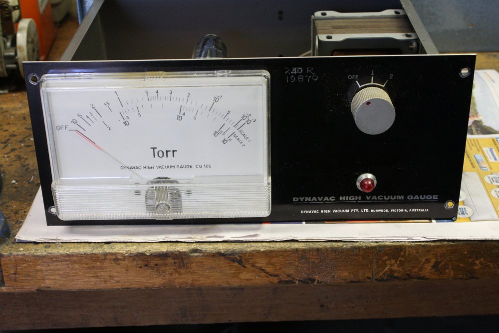
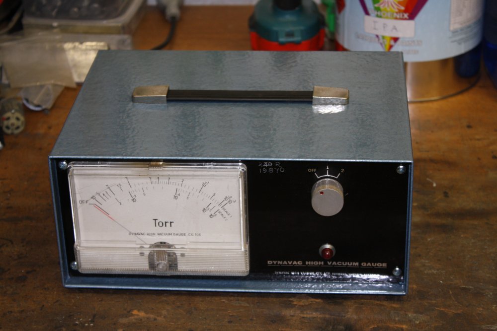
In the the top row center are three Dynavac 'CCH' cold cathode (Penning) gauges. The large 'dynavac high vacuum gauge' unit I repainted previously, should be the matching controller. These are excellent, because they work down to 10-6 Torr, and are incredibly simple, robust and easy to clean. That they are ancient doesn't matter, other than that the controller has no computer interface.
The old Speedivac mechanical gauge at top right is nice too. Its measurement range is 100 to zero Torr. 'Torr' is a unit of measurement that was originally 'mm of mercury' — a pressure of one Torr will lift a column of mercury one millimeter. It was renamed 'Torr' for Torricelli, who invented the idea of air pressure and vacuum.
Atmospheric pressure at sea level is about 760 Torr. So this gauge measures pressures from around one eighth of atmosphere, down to 'zero'. Quotes there because as we'll see, zero is an elusive goal when it comes to gas pressure.
Middle row left, are two Dynavac 'TMH' thermistor heads. Not sure I have a matching controller for these. The controller above is the same general sensor class, but may not be matched to the TMH model.
Center is a Varian ionization gauge head. These are very sensitive, working down to 10-8 Torr. I have several of these, and two controllers:
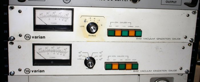
Their main drawback is a hot filament, that reacts with any significant amount of gas. Letting air into a system while one of these gauge heads is running destroys the filament.
That can happen due to a leak, or operator error. Which will be more frequent in my system remains to be seen.
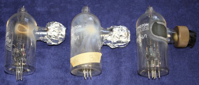 This is what they look like after a 'gas accident'. What you see is 'smoke' condensed on the inside of the glass, with differing appearance depending on the nature and pressure of the gas.
Because this is such a common event, the gauges have two filaments. After one burns out, rotating the connector switches to the spare. All these dead-looking gauges are probably still good, since the 2nd filament is unused.
Bottom left is an Edwards Pirani sensor, model M12. Hopefully working, and I do have the matching controller. In these a sensor wire is slightly heated electrically to a constant temperature. The energy required to keep it at that temperature indicates the gas pressure, since the gas thermal conductivity changes linearly with pressure. Or at least it does below 1 Torr. This Pirani gauge covers the range 100 Torr down to 10-3 Torr.
Bottom center is an Edwards Penning gauge head model CP 25-S. I have the matching controller; an Edwards Penning 8. This works on the same principle as the Dynavac CCH cold cathode sensors. Amusingly the controller has a sticker saying 1978, which gives an idea of the vintage of most of this stuff. I was really hoping this would be complete and working, since it's probably the best choice for primary gauging on my experimental tank. But as we'll see... nope.
Bottom right is the most primitive, but in a sense coolest of all. It's a plain mechanical negative pressure gauge, reading "Vacuum, inches of mercury". One standard atmosphere is 760 mm of mercury, equal to 29.9 inches of mercury. This one and the Speedivac 100 to 0 Torr gauge both work, and agree to within a few percent. They are both definitely going on the vacuum system, and not just because they look great.
However... they can't go on the main test chamber. Reason being they have a fair amount of internal volume, small openings for the piping, probably have internal oil contamination, and it is impossible to clean the insides. The result is they present large 'virtual leaks' to a high vacuum system, as gas and volatile oil molecules gradually find their way out through the small pipework. Where I can use these is on the intermediate vacuum section - the inlet to the roughing pumps, downstream of whatever high vacuum pump I end up using.
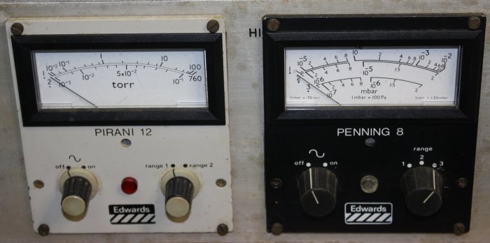 The controllers for the Edwards Pirani and Penning gauge heads. Yes, they need cleaning. Not to mention testing and whatever repairs they may require. Unsure if I have schematics.
Speaking of cleaning, today I tried cleaning a couple of the cold cathode sensors. Unlike that rotary pump these are easy because they are small, and there's no oil involved. Well, easy to do 'basic' cleaning anyway.
 |
 |
 |
1. The Dynavac CCH cold cathode gauges. The brown crud is probably mostly organic compounds such as from oil pumps, that was ionized by electron bombardment in the gauge cavity, then deposited on all exposed surfaces. It's resilient, and takes a lot of sanding with fine emory paper (I used 1200 grit) to remove.
2 - 3. Washed with tap water and common cleaner (spray'n'wipe) while doing that. Then rinsed with distilled water, then a final clean with IPA. The hardest part to clean was the ceramic insulator post supporting the center electrode. I didn't want to use abrasives on this for fear of scratching the surface. So scraped as much gunk off as I could with a soft metal edge, then polished the rest off alternating with a buffing wheel, detergent and IPA.
Anyway, all good. These ones are easy to disassemble, clean and reassemble.
 |
 |
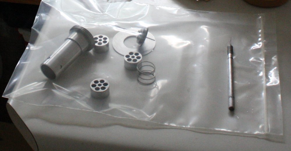 |
Unlike this little bastard. For starters, turns out it's missing one of the four magnet rings. I didn't disassemble it before, so that was lost/broken by the previous owner. I know it came from an environment where it was used by students, so maybe some klutz had it apart and dropped one of the magnet rings, shattering it. Then didn't tell anyone. Great. What's the bet there will be no way to obtain a replacement, for such an old gauge head?
Secondly, those three inner electrodes. Argh. The advantage of Penning gauges is supposed to be 'easy cleaning', but a small cylinder with an end cap with seven holes, is not easy to clean. These were a major pain.
Last pic is them all done, though I skipped the IPA wash. I put them in a clean ziplock bag as I completed each one, to protect from dust and fingerprints.
There's also what seems to me to be a design flaw — the split plastic threaded sleeves project a little past the end of the aluminium body end. They block the end cap from being tightened down well on the O-ring, and also tilt the end cap slightly off axis so the center electrode isn't repeatably positioned at the center of the assembly.
If I can find a replacement magnet I'll bother to fix those problems.
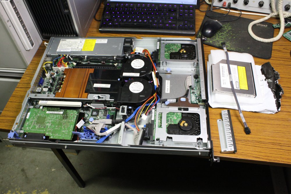
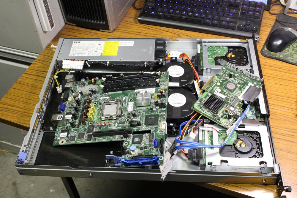
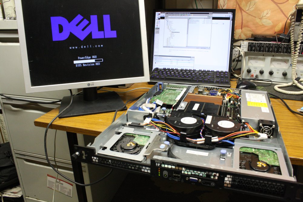
20151214 Dell rackmount server.
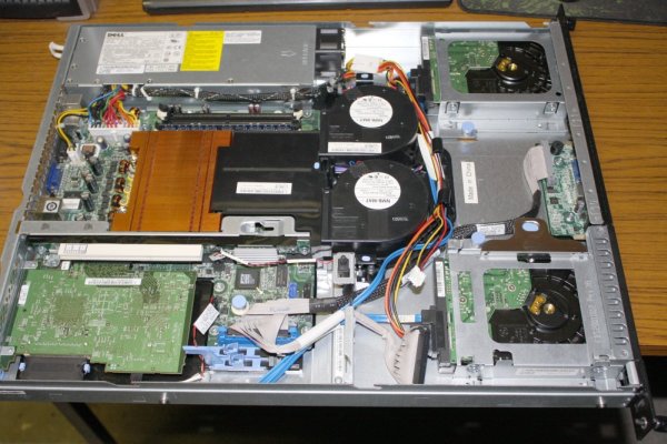 Back on 7th Nov a friend gave me an unwanted Dell Dell PowerEdge 860, 1U high rackmount server. Manufactured in 2007, it is still very clean inside so I don't think it's seen much use.
Not sure what I'd use this for. It's very light on I/O; just 4 USB, 2 gigabit ethernet ports, VGA screen, PS2 keyboard and mouse. But it does have one spare PCI slot. Two HDs, in RAID-2, but they are only 80GB. No parallel port or audio I/O, so using it to replace my media server and Black-Rack controller is out.
However it's a fast and neat looking machine, I'm sure I'll find some use.
Once it's usable that is.
 |
 |
 |
 |
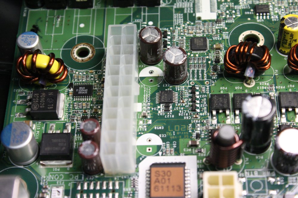 |
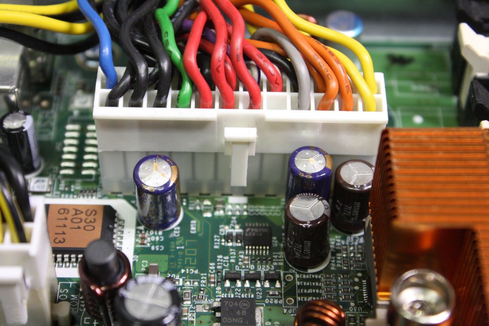
It has a couple of problems. A minor one is the two caps that have failed. (See Pic 1: domed tops, and traces of leaked electrolyte.) The machine still boots, but these have to be replaced.
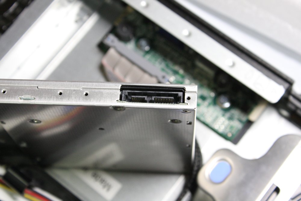
The other problem: it boots to Linux but the login password is forgotten. Oh easy right? Just boot from something like the UBCD (Universal Boot CD) and use the tools on that to remove the old password. Well yes, except there is no CD drive. And I don't feel like learning how to put UBCD on a USB flash drive just now. Anyway to be more usable this machine needs a CDROM drive. Preferably a CD/DVD/burner/rewriteable drive. It has a slot for it, but it's blanked.
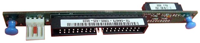 There are also cables for it, IDE and power. But to connect to the standard laptop optical drive that would fit, requires this interposer board. Which I don't have.
I can't find one for sale in Australia. Several overseas, but with postage and the crappy Oz exchange rate, it would be pushing Au$30. Alternatively (I thought) I could just buy a cheap SATA optical drive, and plug it into one of the spare SATA ports on the motherboard. So I ordered a US$12 + free shipping drive from Hong Kong.
Pic 2. It arrived today. Only... what is that power connector? (Pic 3) It is not the same as a hard drive SATA power connector. I've never seen it before. And the guys at the local computer store have never seen it before either. Great. Now I have to go hunting its mate.
Meanwhile I changed those bad caps.
4. The motherboard pulled out.
5. Two bad caps removed. Man, solder sucking small through holes free of solder on a board with a lot of internal copper planes is a huge pain.
 |
 |
 |
 |
 |
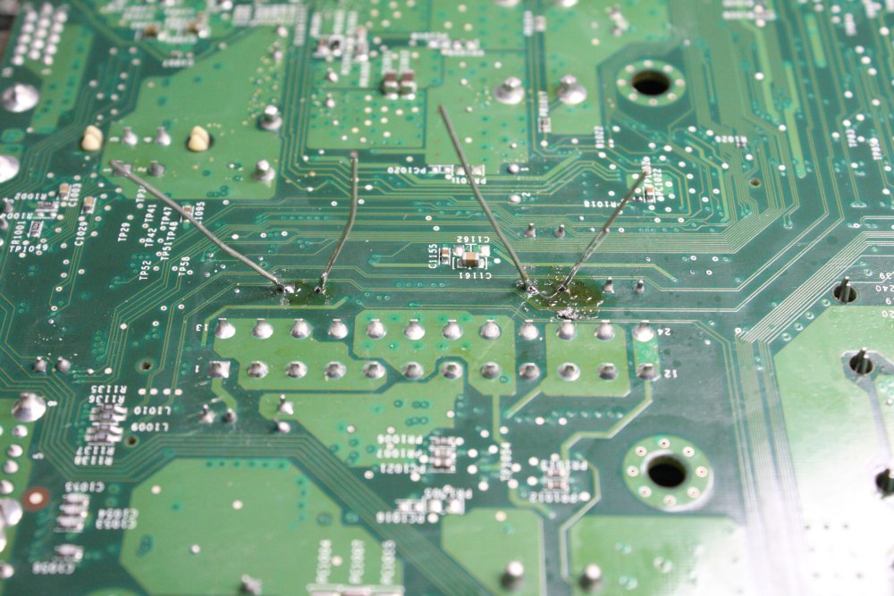
1 - 2. New caps soldered in, then clipped and the mess cleaned. Most of the mess was from the painfull solder-sucking efforts.
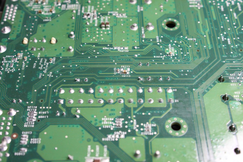
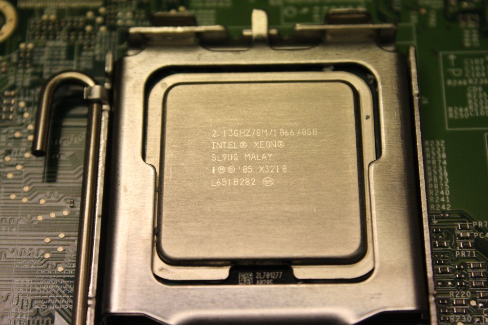
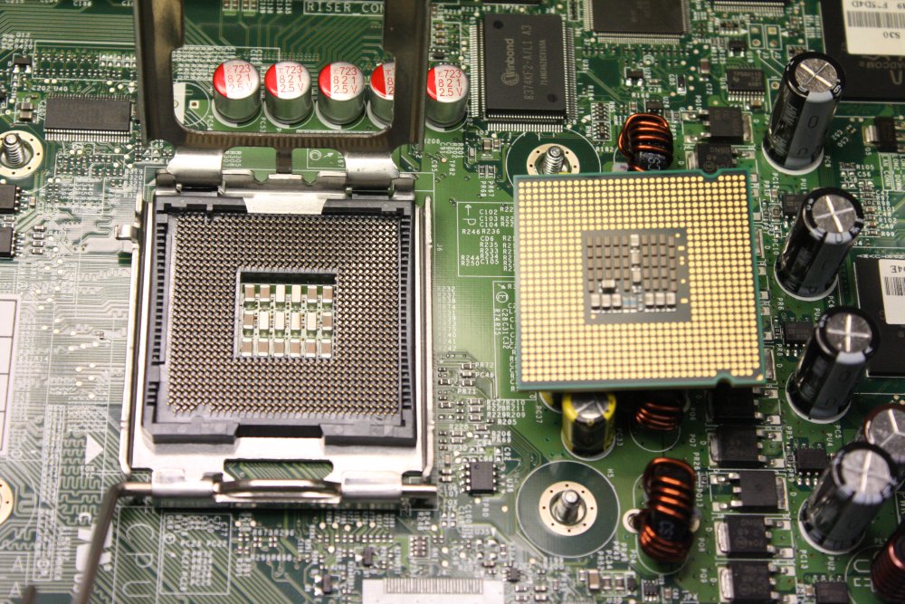
3 - 4. While I'm attempting to ruin the motherboard I may as well take the CPU out for a look too. I like these pin-less kind. No more bent CPU pins, the bane of early PC work.
5. After reassembly (yes, with heat sink paste on the CPU) it still works. And I still don't know the password. Hopefully I can find that 'new SATA power plug' quickly.
Later: Seems the search term for these is 'Slimline SATA Cable'. Plenty of them, and cheap. Ordered 4 for $9. So this machine goes back on the shelf for a few more weeks till those arrive. Lucky I don't need it in a hurry. Also the slimline SATA is a well established standard. So much for the expertise of my local computer store. And my ability to google pre-emptively.
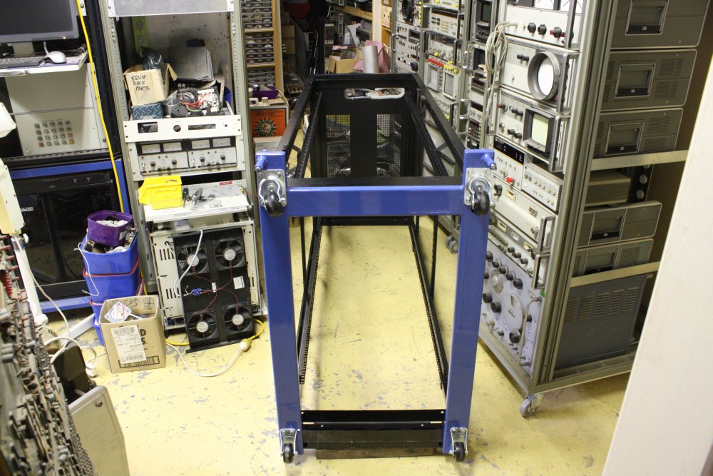
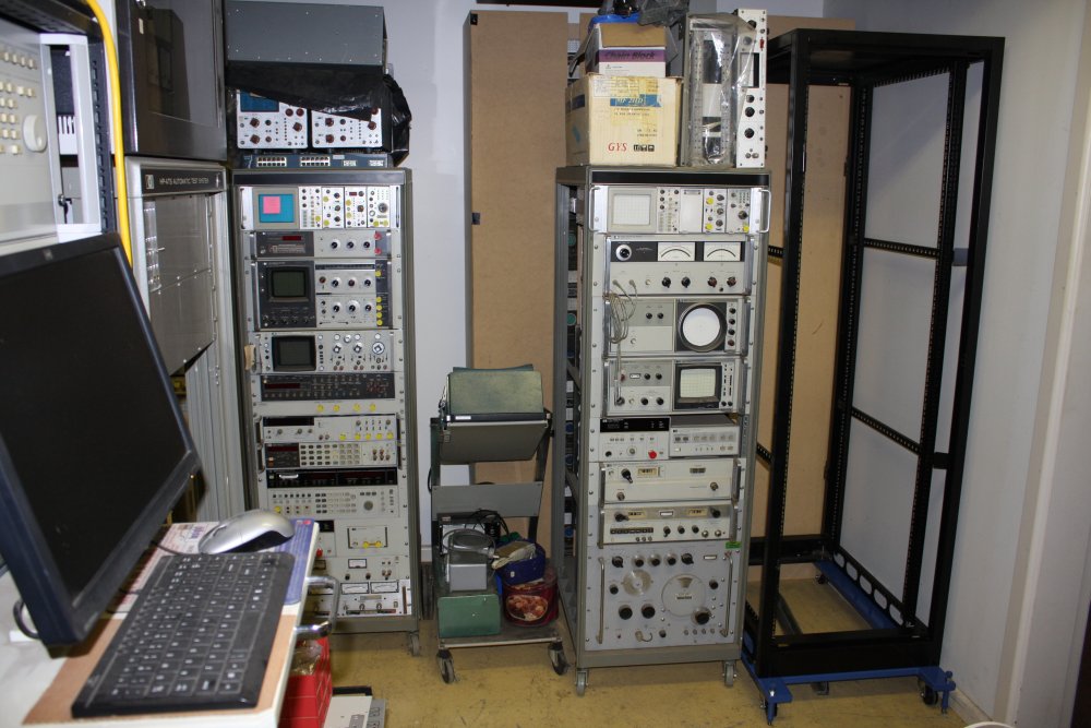
20151218 New Rack
This page is getting way too long; better stop soon. Just a few more reining chaos examples.Remember this was supposed to be an exercise in sorting and tidying. Well, one of the problems is there are a number of bits of rackmount gear lying around in various stages of 'needs work'. Some of them have been in pieces for many years. Not because I'm particularly slack (though I am), it's more due to the last decade being one long train of major priority interrupts, including owner-building efforts, marriage dramas, health dramas, and more. Sometimes I'd acquire a piece of old gear needing work, take it apart to evaluate/fix it, then get flung into some new torrent of time-suck beyond my control.
Also, for years I've been searching for one more equipment rack the same as the five I have along one wall in the lab. Thanks to a Bankstown Council building approvals officer being a c*nt when I was applying for permission for this garage workshop, the building ended up being a half meter shorter than originally planned. For no good reason; he just wanted to screw me around. I learned later (way too late) that the 70 sq m out-building area limit applied to interior space, not the outer dimensions — as he'd used to justify modifying the plan. Which he of course knew perfectly well.
That missing half meter really messed up the workshop layout.
Among other things, there should have been plenty of room along that wall segment for six equipment racks, loosely spaced.
Instead there is just enough room for six racks, so long as they are all the extra narrow old-style Hewlett Packard ones.
If even one is a wider modern style rack, six can't fit. I have five of the old HP racks, and searched and searched for one more. No luck. I suppose they were always rare in Australia, and now it's decades since they stopped being made.
Meanwhile, it's becoming urgent to get the various bits of 'waiting for attention' gear off the floor, put back together and in a rack. Not least so I can get at them individually, and make a start on fixing them.
So I gave up waiting for another old HP rack. I have a spare modern rack, and I'll use that. This does mean there'll have to be some layout rearrangement, and it won't be quite what I'd originally planned.
Generally a layout change would involve a scale drawing and paper puppets representing the various pieces of gear, to play around and see what worked least horribly, in my too-small space. But not this time! Since all the relevant pieces exist, and though very heavy are on castors. I can 'play around' with the real things easily.
One of the HP racks is allocated as 'power distribution and process control' for the vacuum experimental setup as well as all the other racks. It worked out well to move that rack from the wall to join the cluster of units in the center of the room.
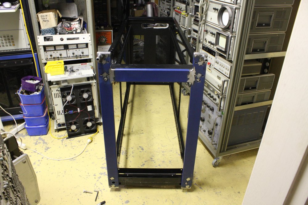
And so, another rack to set up. For a change, a photo set with minimal talk-talk.
 |
 |
 |
 |
 |
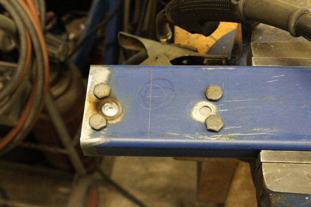
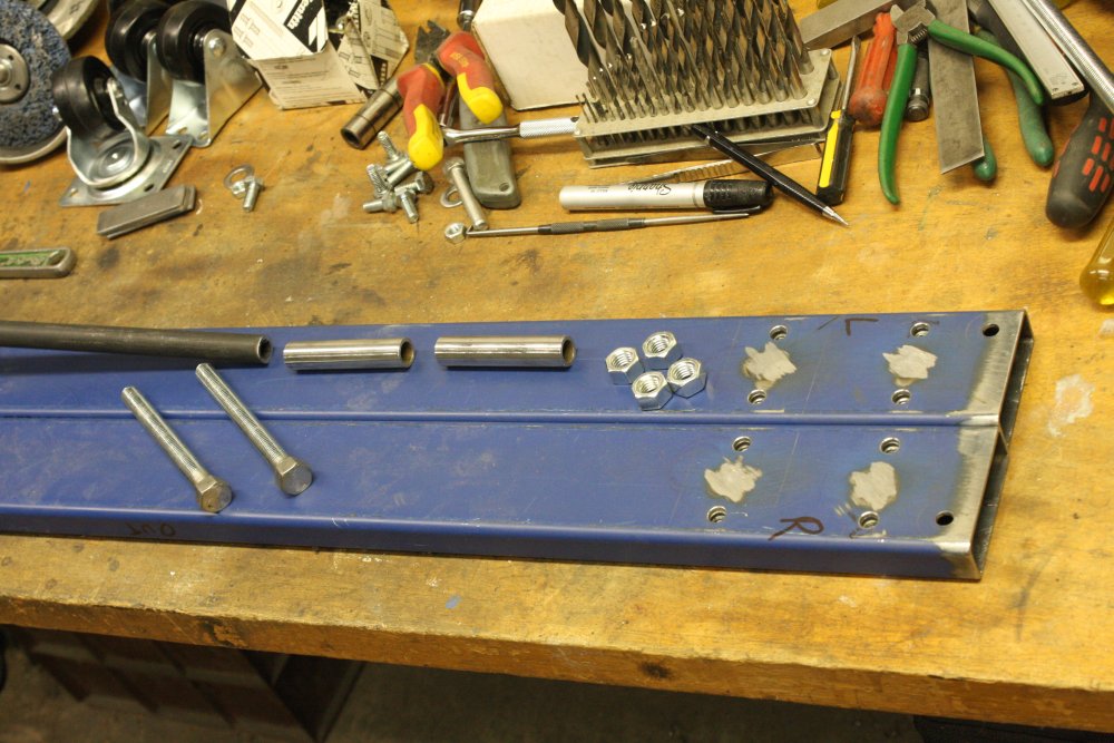
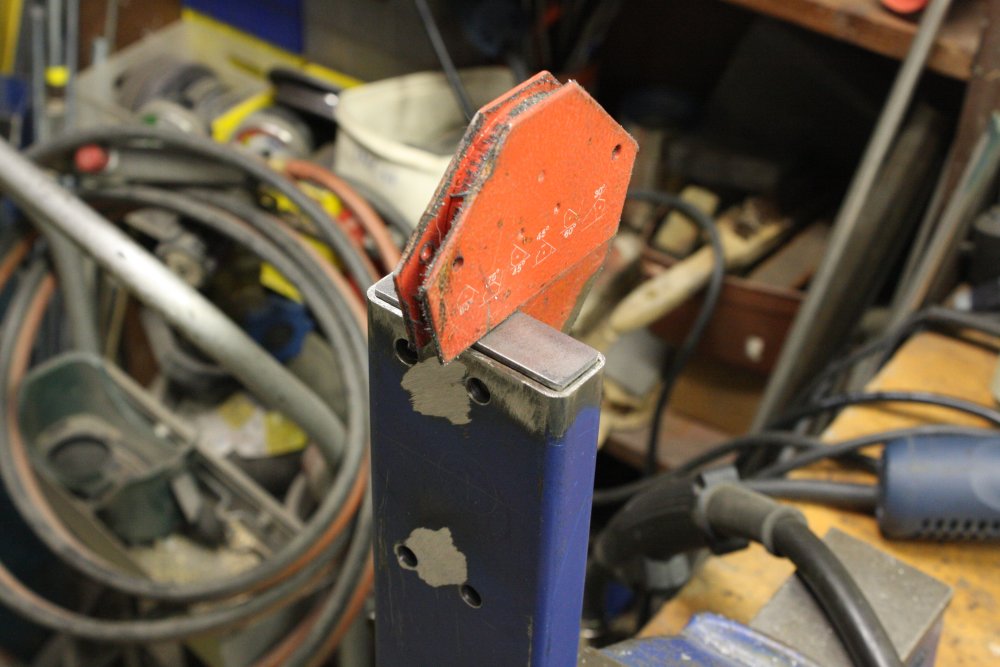
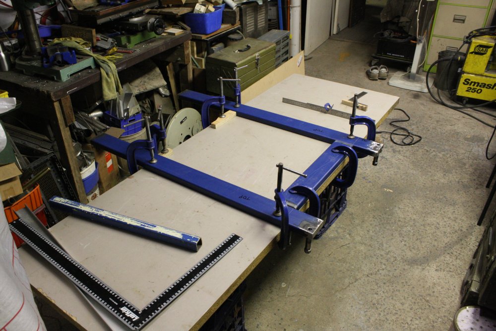
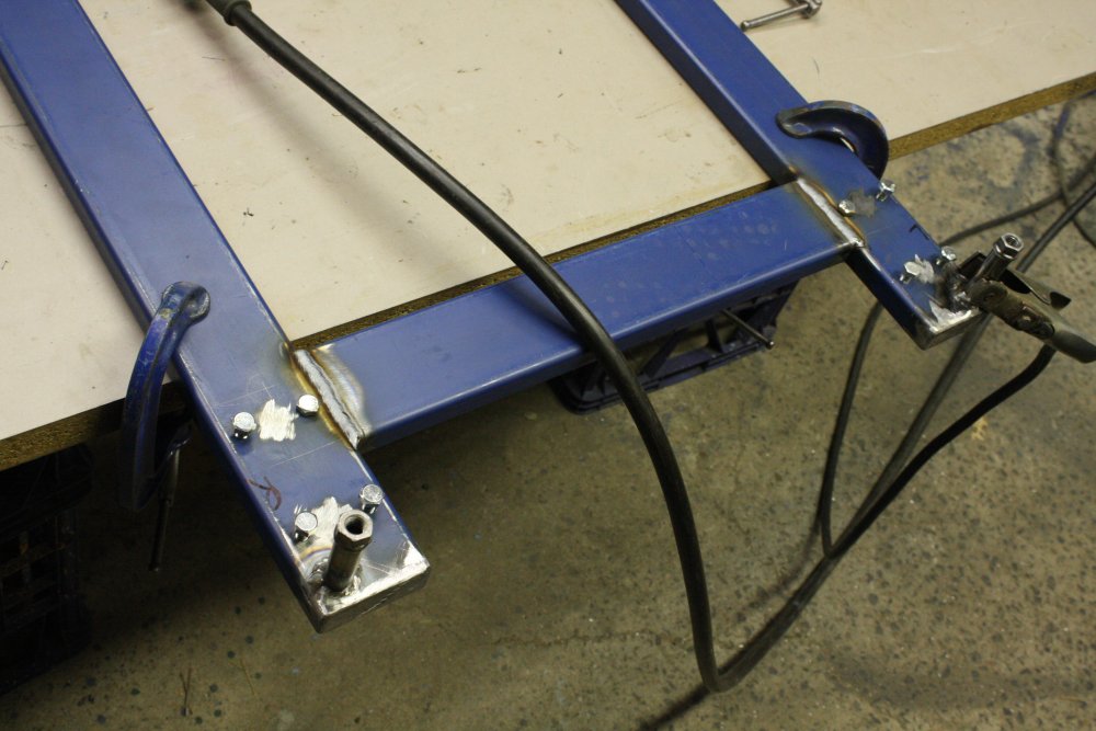
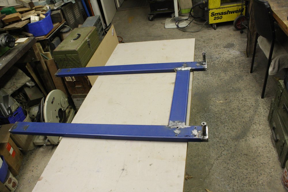
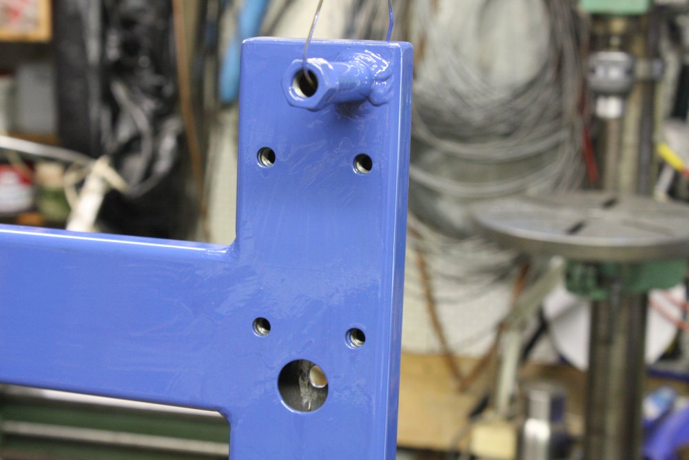
#4: At least this time I thought to drill all the holes in the base sections before welding them together. Much easier.
 |
 |
 |
 |
 |
 |
 |
 |
 |
 |
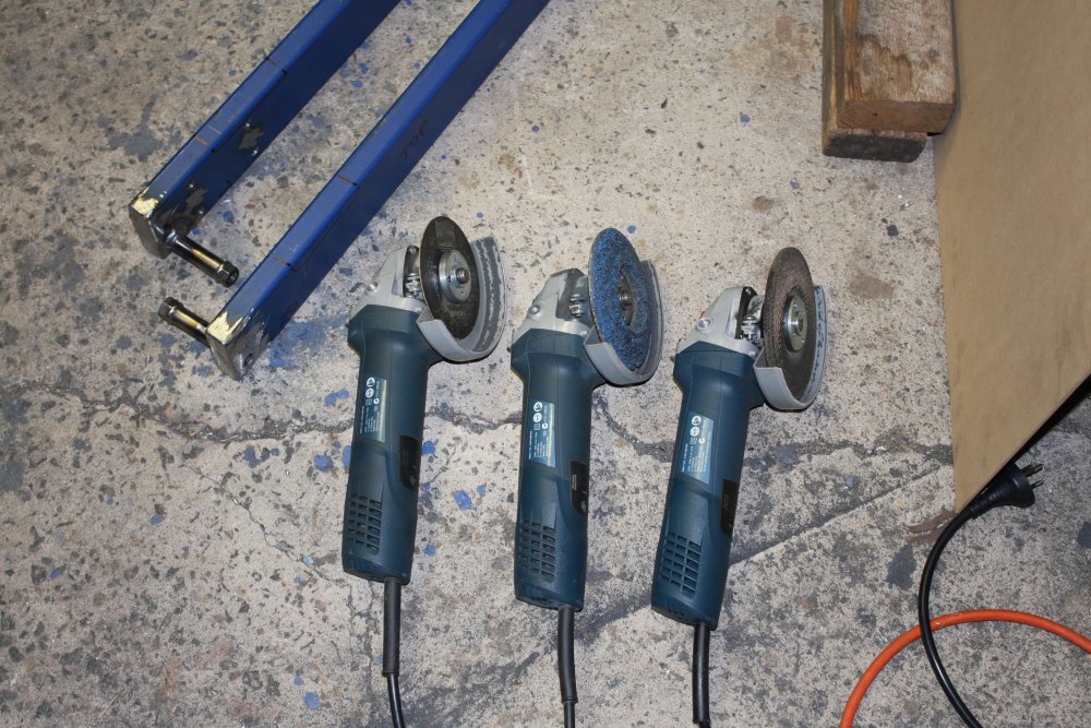
#3: Recently I bought a 3rd angle grinder (they are $75.) Hoooray! No more disk swapping. Having grinders dedicated to thin cutting disk, paint stripping and grinding is great.
 |
 |
 |
 |
 |
 |
 |
 |
 |
 |
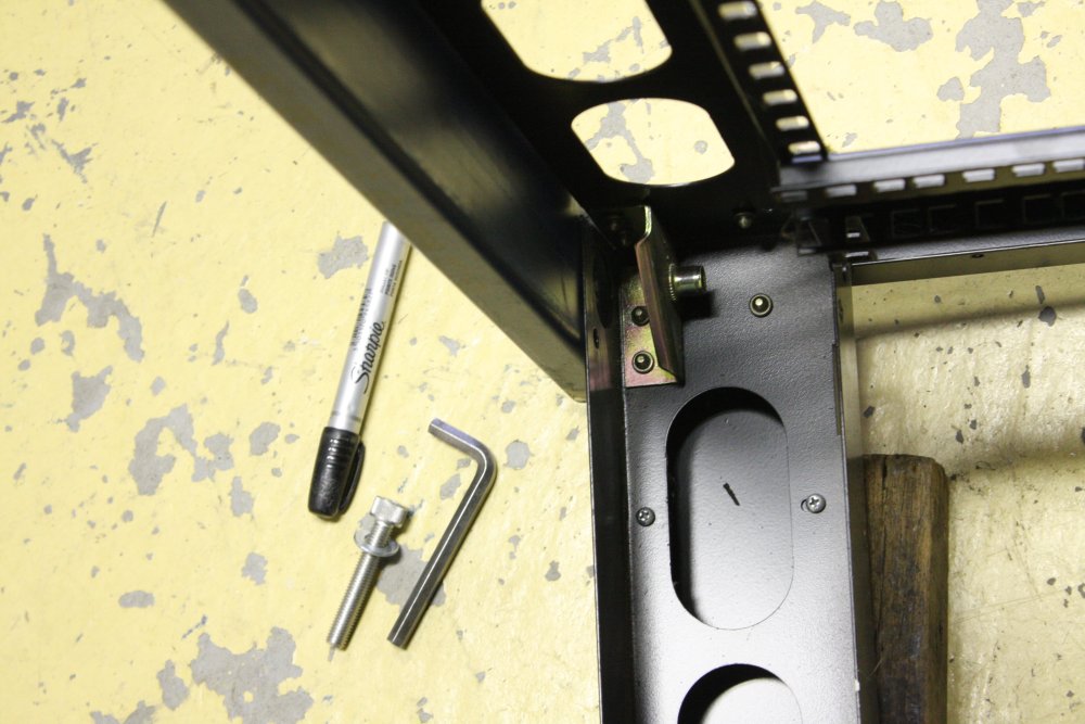
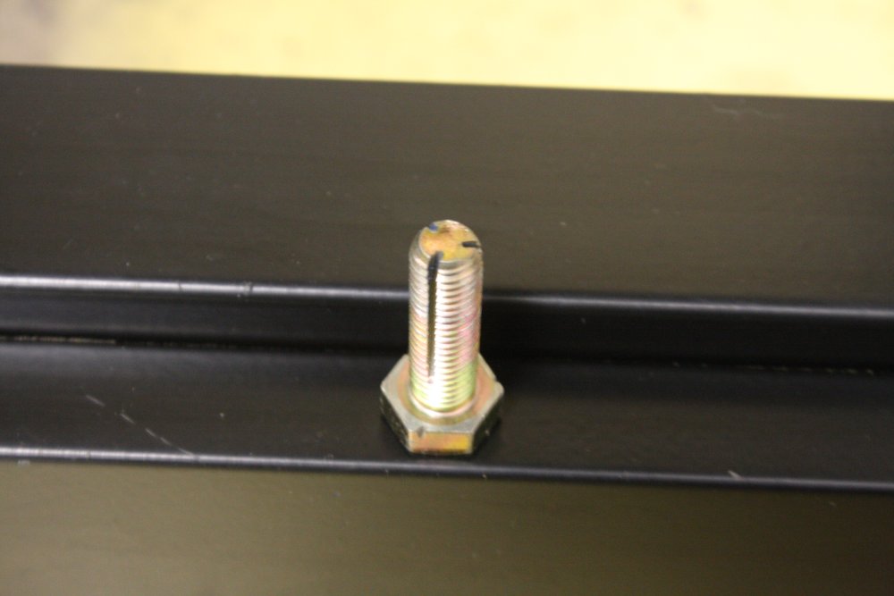
#4: How to clean paint out of internal threads: cut slots in a bolt that fits, screw it into the hole.
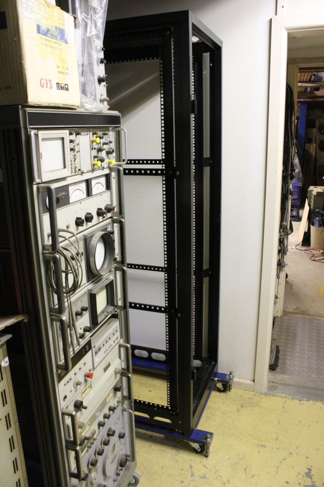
#5: With only 5 racks in the row, the spare space just happens to fit the scope trolley perfectly.
 |
 |
 |
 |
 |
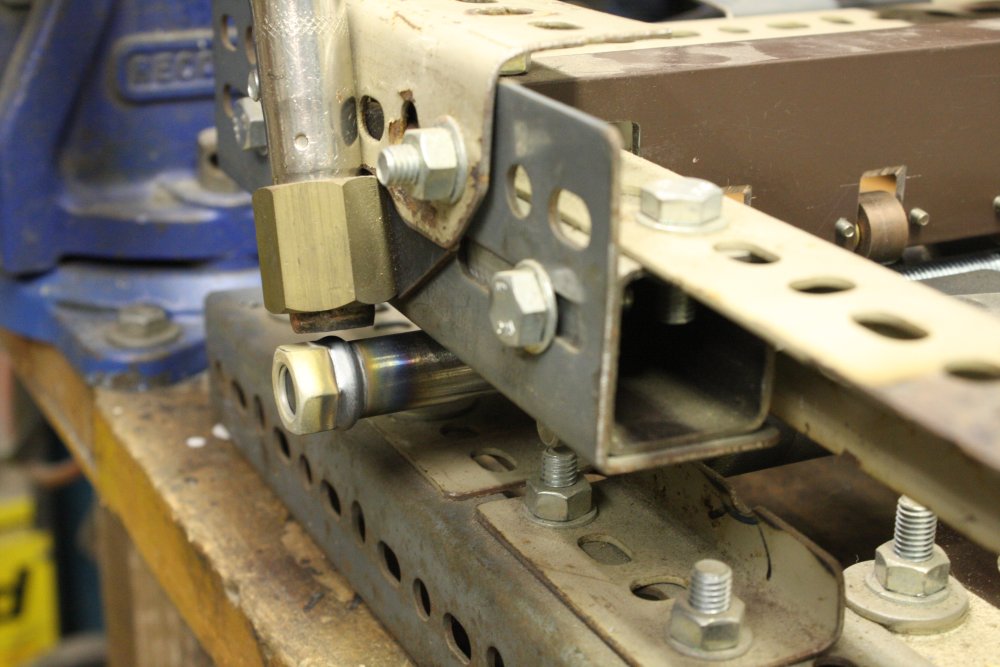
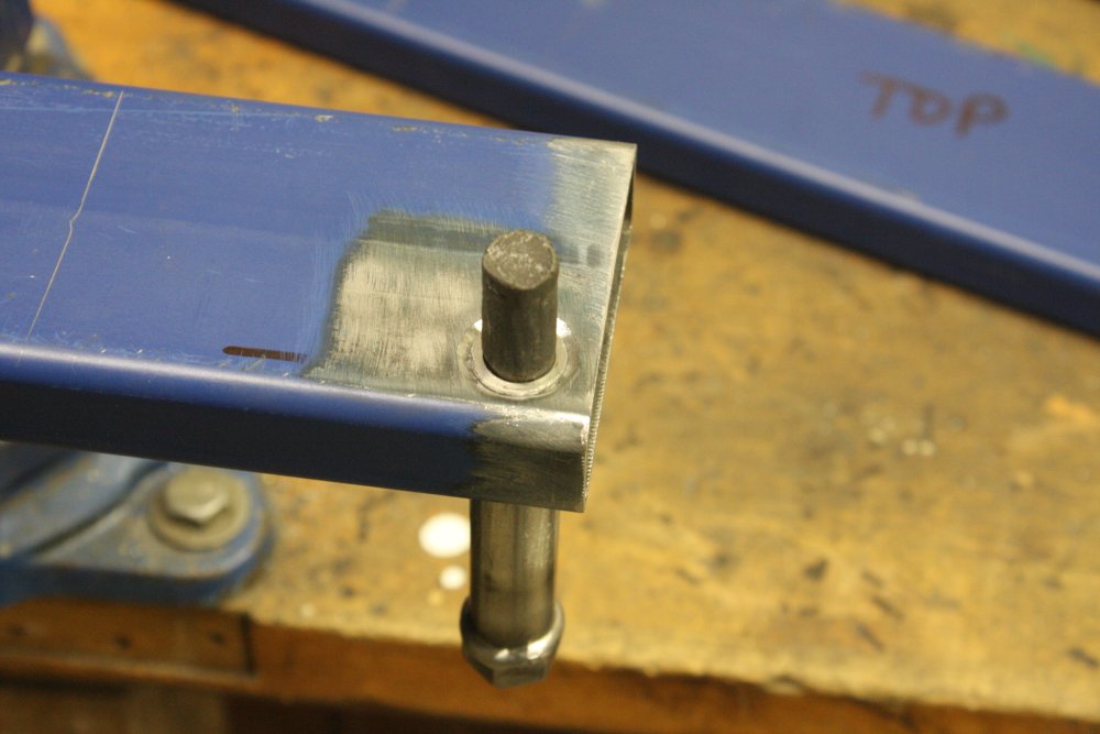
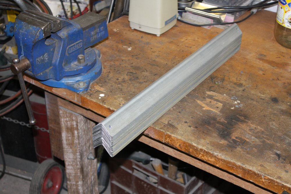
#1 - 3: This rack lacks slides for the equipment. With light gear these can be skipped, but almost everything going in here weighs a ton, so I needed to make slides. I duplicated the slides that fit in the HP racks, so I can use them in those racks too.
Funny - two six meter lengths of this L section cost $75 — same as the angle grinder.
#4: Coming along. Starting from the bottom in the new rack (far right):
- The HP 8181A & 8182A are spare parts for another rack project.
- The HP 3497A data acquisition and control unit is spares and extra modules for the unit in the vacuum system Black Rack.
- The HP 6268B power supply (40V 30A) was a slave unit, without front panel controls. Same as some other similar units. I have the needed parts for all of them, just haven't fitted them.
- The SCP 2160 pulse analyzer is a fascinating piece of ex-military sig-int gear, but I have no manual. Yet.
- The Fluke 332A voltage standard was sort-of working till the old mechanical chopper-amp failed. I'd been given a replacement all-transistor chopper amp board, but the 332A unit as I originally received it was also missing the inner guard shielding metalwork. I finished making replacements, but then got sidetracked before testing out the unit with the new chopper amp. This had been sitting in pieces for a while.
- Fluke 5200A Programmable AC Calibrator — Bought as 'not working' it seems repairable. Has a fault on the main output amp board. Had been sitting in pieces, and also was missing some blanking panels, which I made when reassembling it.
- EG & G 128A Lock-in Amplifier. Condition unknown. This was originally waiting till I found a manual, which I now have.
I'll be glad to see this back in one piece. Hmm. The surviving side frame is filthy. I'll take it off and restore it, to match the 'new' one, which really does look new. Oh, and for those who know this gear, yes I do have the unobtainium correct probe.
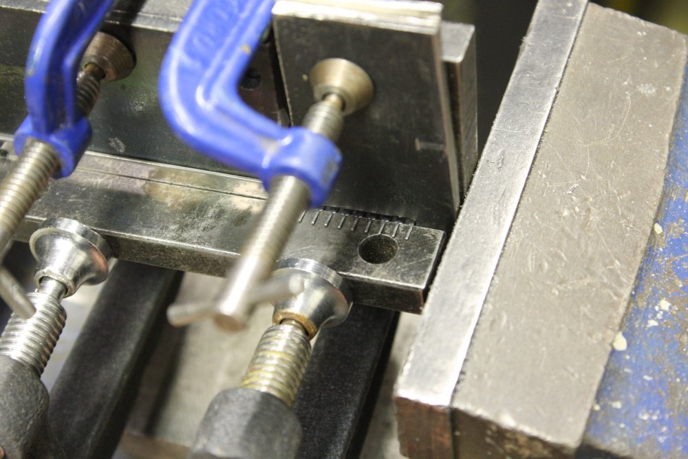
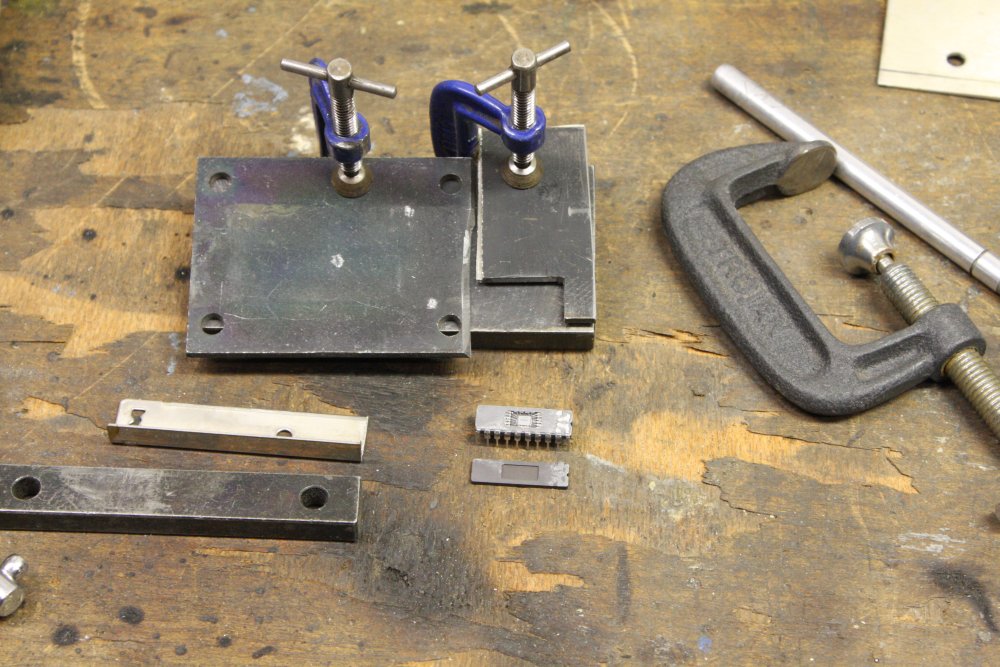
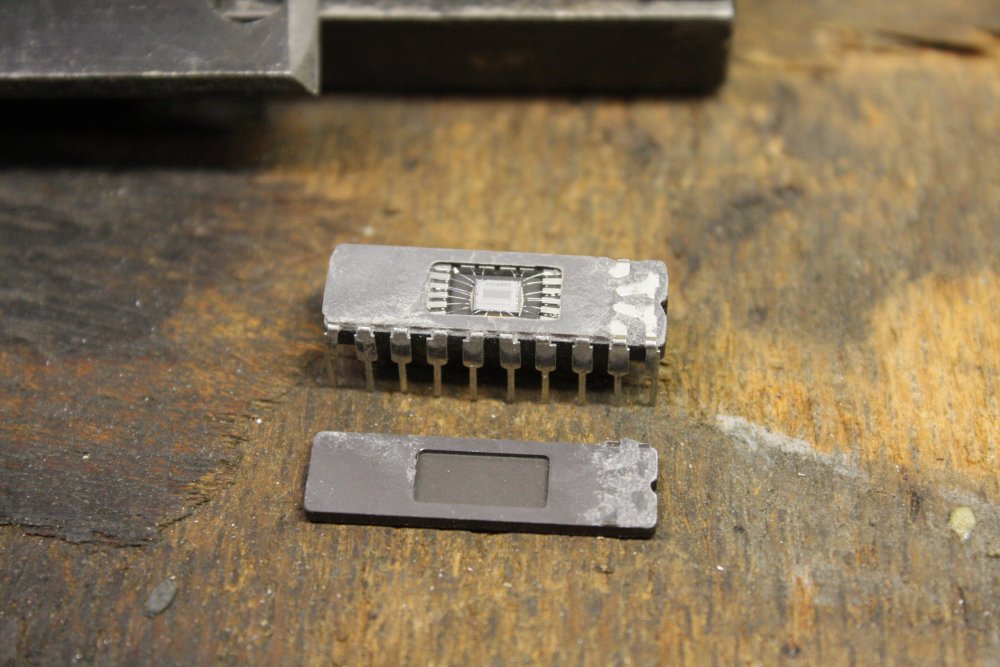
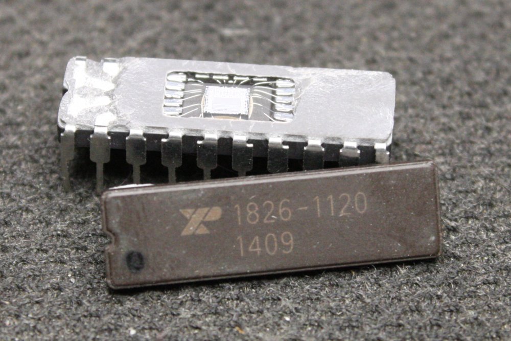
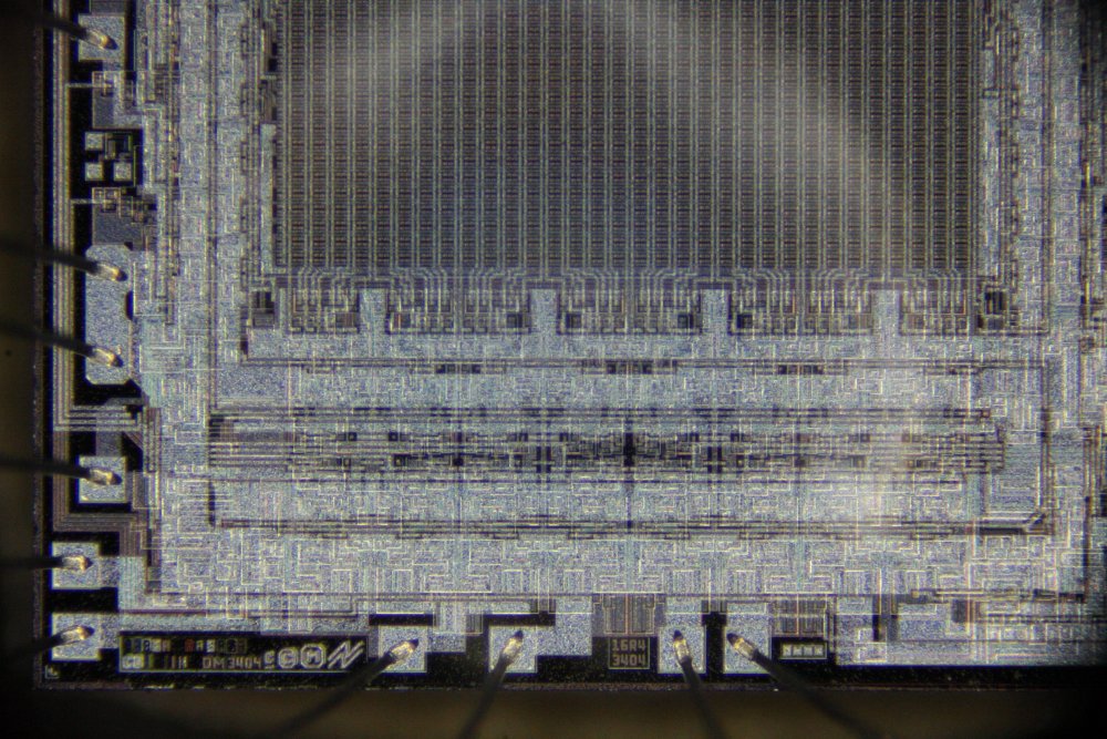
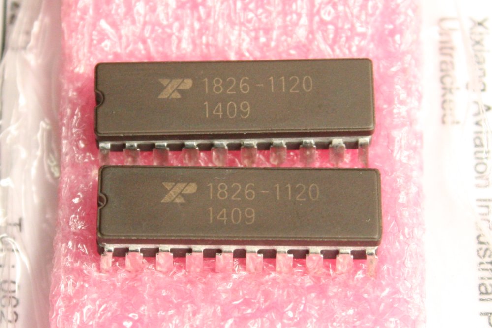
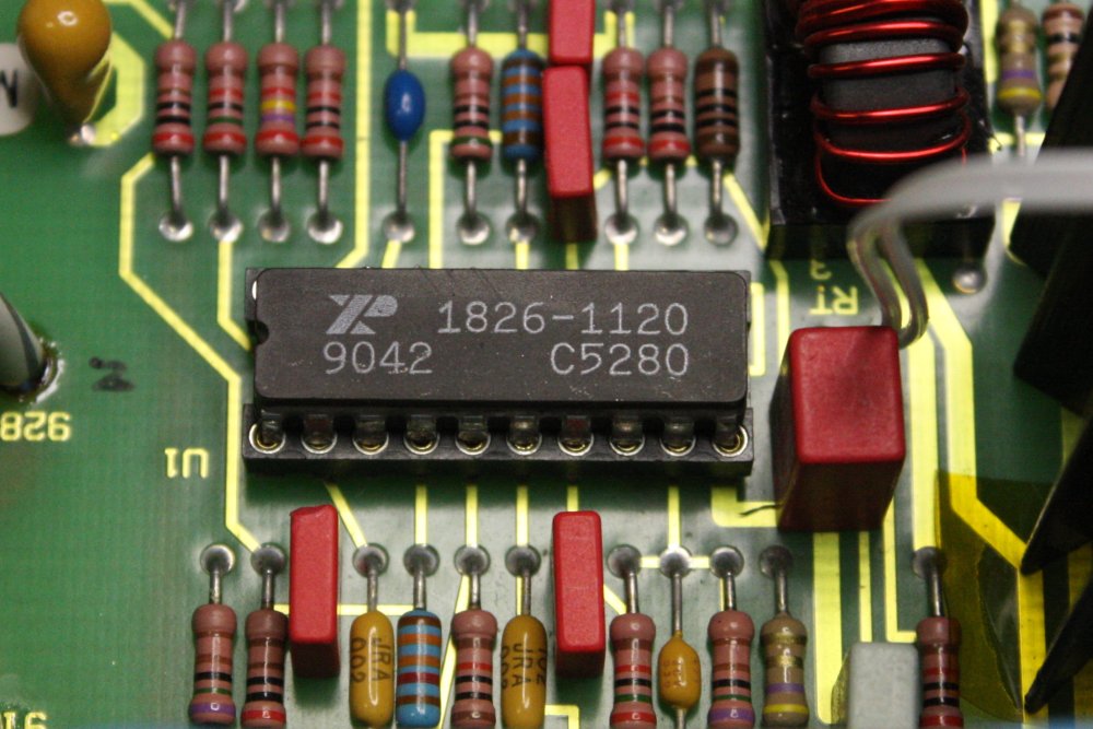
There's also a HP 54120B, bought as spare cards for my two working units. This one has a power supply fault, that I'd been working on then got pulled to something else. Since then I obtained the schematics but found the likely fault is an unobtainium IC, HP part HP 1826-1120. It's a 20 pin ceramic DIL switchmode regulator IC, and there's not even data on it online, let alone any for sale anywhere. Well, time to have another go, then putting it back together (whether fixed or not.)
More below.
Ha ha... all this isn't even getting warmed up on 'fixing gear', it's just floor clearing. Going through all the non-working and untested gear I have collected, and getting most of it working is going to be a great deal of work. Retirement passtime... which is partly the intent.
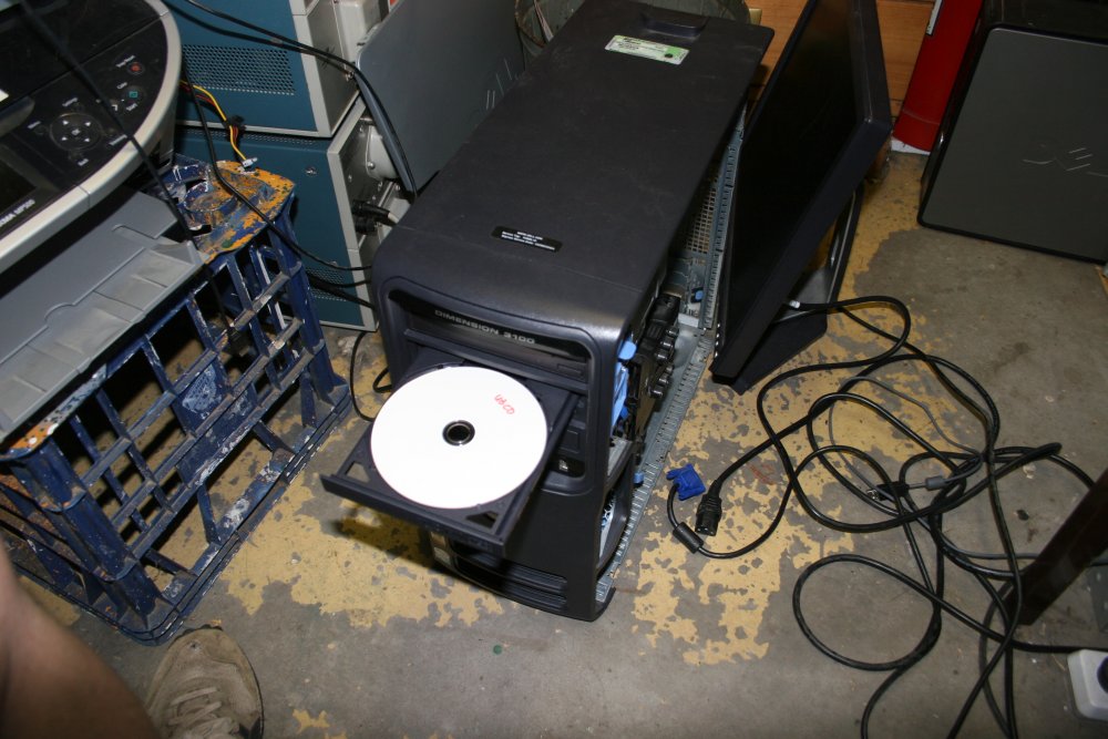
20151221 Dust Can Kill
More floor clearing. Back in March 2014 I'd picked up a street toss PC, A Dell 'Dimension 3100'. It booted, but urrgh... the typical horrible mash of so many semi-hostile things installed that the machine is slow as treacle despite being an Intel P4 HT CPU. Task list that doesn't fit on the screen.I uninstalled a few bits of useless crap, and it became usable enough to play with. The objective is just to have a quick look through for anything I might want to keep, before formatting the hard drive and starting clean. Then I notice that... ha ha... it has two DVD drives installed, one is a writer. And that one is showing folders present. I open the drive and sure enough there is a burned DVD in it, handwritten "UBCD" label.
A quick browse through it, and it appears to be a really good compendium of many, many different utilities and boot tools. Cool. I love it when people have forgotten to remove useful/interesting CDs from discarded PCs. Especially ones I had never heard of, thus informing me they exist. But there's not one single 'about me' text file on this one anywhere that I can see. So finding out what it is and does will take some research.
It was late, I put the machine aside on the floor. I will look at it next free moment, then install a clean Windows. It's very dusty too, I should blow it clean with the compressed air gun. It was 'off', but still had power applied.
Next morning I find that the workshop master residual current detector circuit breaker has dropped out. I pop it back, it stays. Everything seems to work. Huh. Was that just one of those random dropouts that happens now and then, due perhaps to spikes on the grid?
I forget about it, and go on with other stuff.
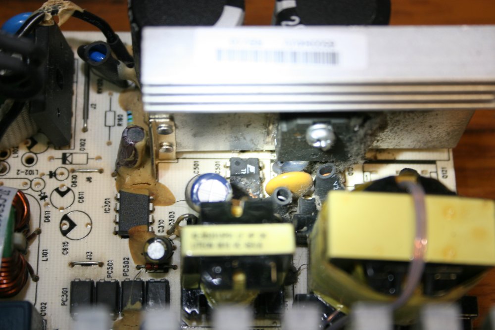
Another day later I try the PC. Dead. On opening it up I found that dust accumulated in the power supply had caused an arc-over from the PCB underside, to the metal case. Yes, you'd think in a Dell there should be an insulating sheet between the PCB and metal case, but there wasn't. There was a nylon standoff, but it seemed the arc had initiated along the surface of this, probably due to dust.
That will teach me not to postpone cleaning out heavy dust deposits.
Rather than ditch the PC, or replace the power supply I thought I'd try fixing it, as an exercise. No schematic available, so purely by sniffing around.
 |
 |
 |
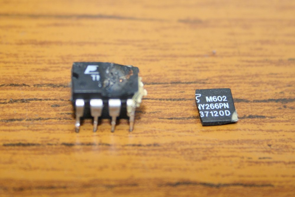 |
Or in this case, looking for exploded ICs. Easy.
Four weeks later the replacement regulator ICs TNY266PN arrived. 10 for $11. And... nope, power supply still doesn't work, there is also other damage. Which turns out to be a one ohm surface mount resistor, that had all its resistive film burned off by the arc.
Another 4 weeks for those to arrive... by which time this PC had achieved oneness with the floor junk continuum.
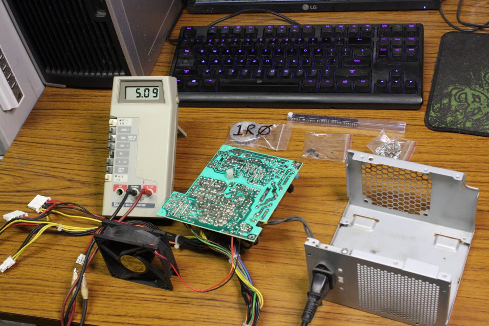
Now in Dec 2015 I soldered in the missing resistor, and the power supply works. So does the PC.
 |
 |
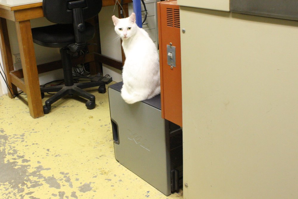 |
It's going to have to stay on the floor a while though, since it has been appropriated as a cat pedestal.
20151223 Microwave oven Inverter
The evolution of microwave oven inverter technology involves doing high power, high voltage switching converters at minimal cost, and is quite interesting to watch. I had the thought that at some point a version may turn up that is easily hacked to use as a cheap high voltage lab bench power supply. So when I see street-tossed inverter ovens I grab them and dissect to see whatever new developments have occured. For eg see 20130308 Microwave Hacks. That one turned out to use a proprietry analog control IC with no data available, so wasn't worth trying to reverse engineer. Same story with all the Panasonic inverter ovens I've found.Recently I found a SHARP 1200W inverter microwave. It was sitting rear-up, and had been rained on, so the insides were wet. Also the mains cord had been cut off. I wasn't feeling well then, so left it in my car a few days. Which served to bake it dry.
On opening it today, found it had been used in a very grease-misty place, so the PCB and fan have heavy grease deposits.
Turning it on the controler works, but no microwaves. (My simple test is a small fluoro tube put inside the oven.)
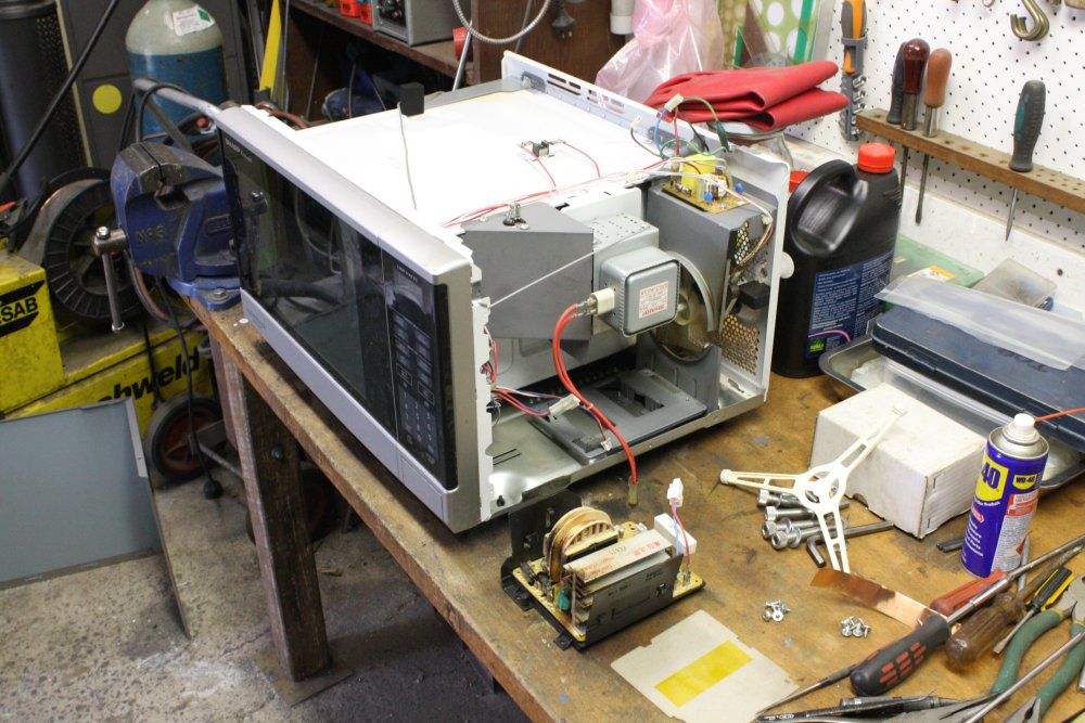 |
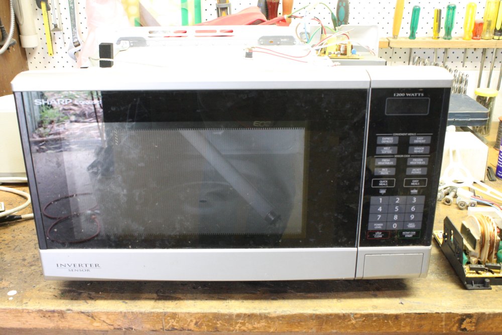 |
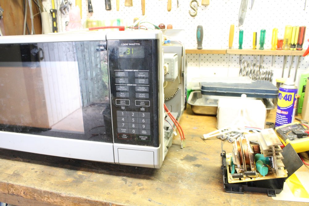 |
I removed the inverter board, then happened to run power again. Amusingly the controler works same as before, and thinks it's running the machine. It can't tell the inverter board is missing.. Seriously? I thought there was 2-way coms? I can see components on the inverter board that are definitely current feedback sent to the controler. Maybe that isn't implemented on the controler? Or it's simply coded very poorly? Perhaps they decided consumers don't need no steenking fault error codes?
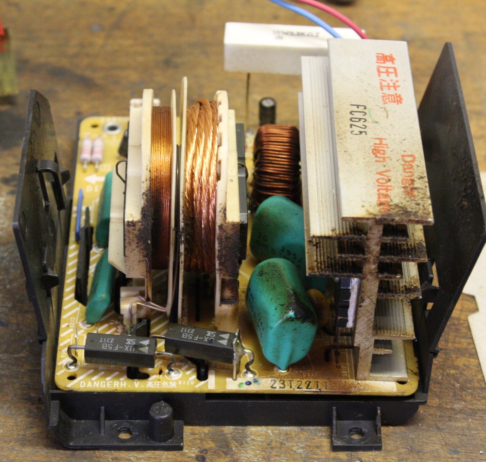 |
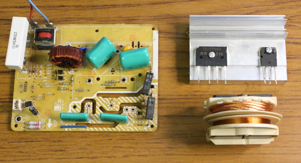 |
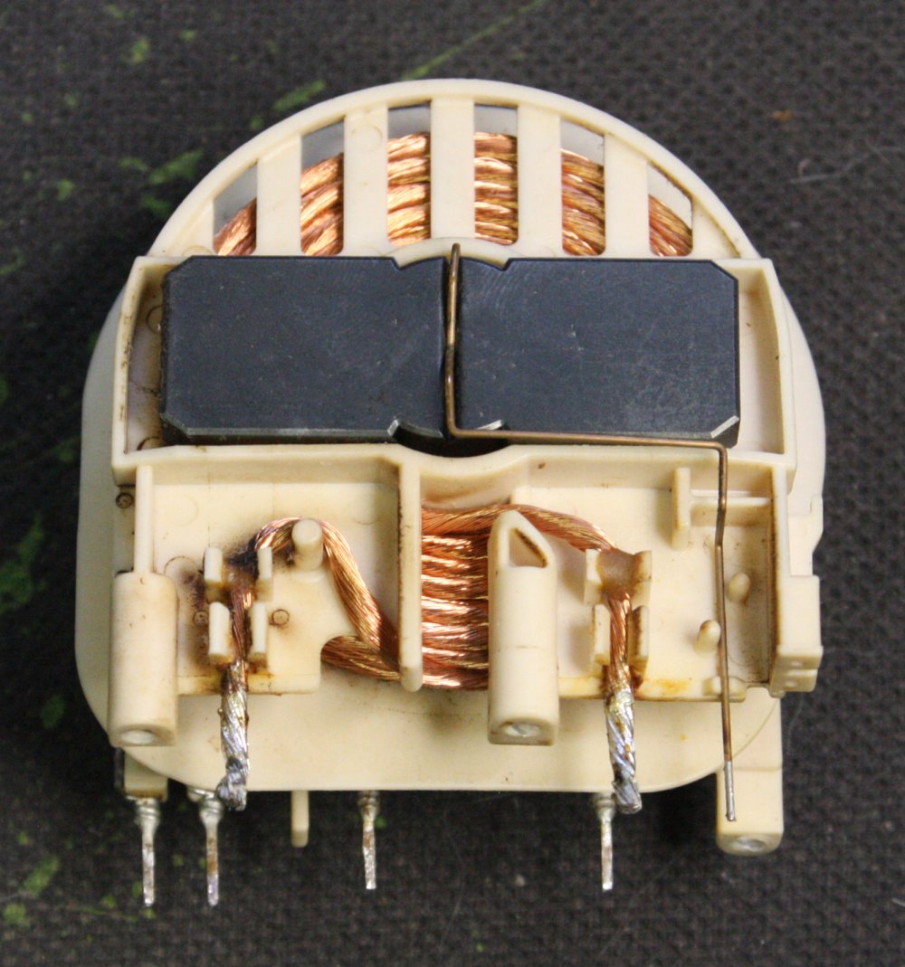 |
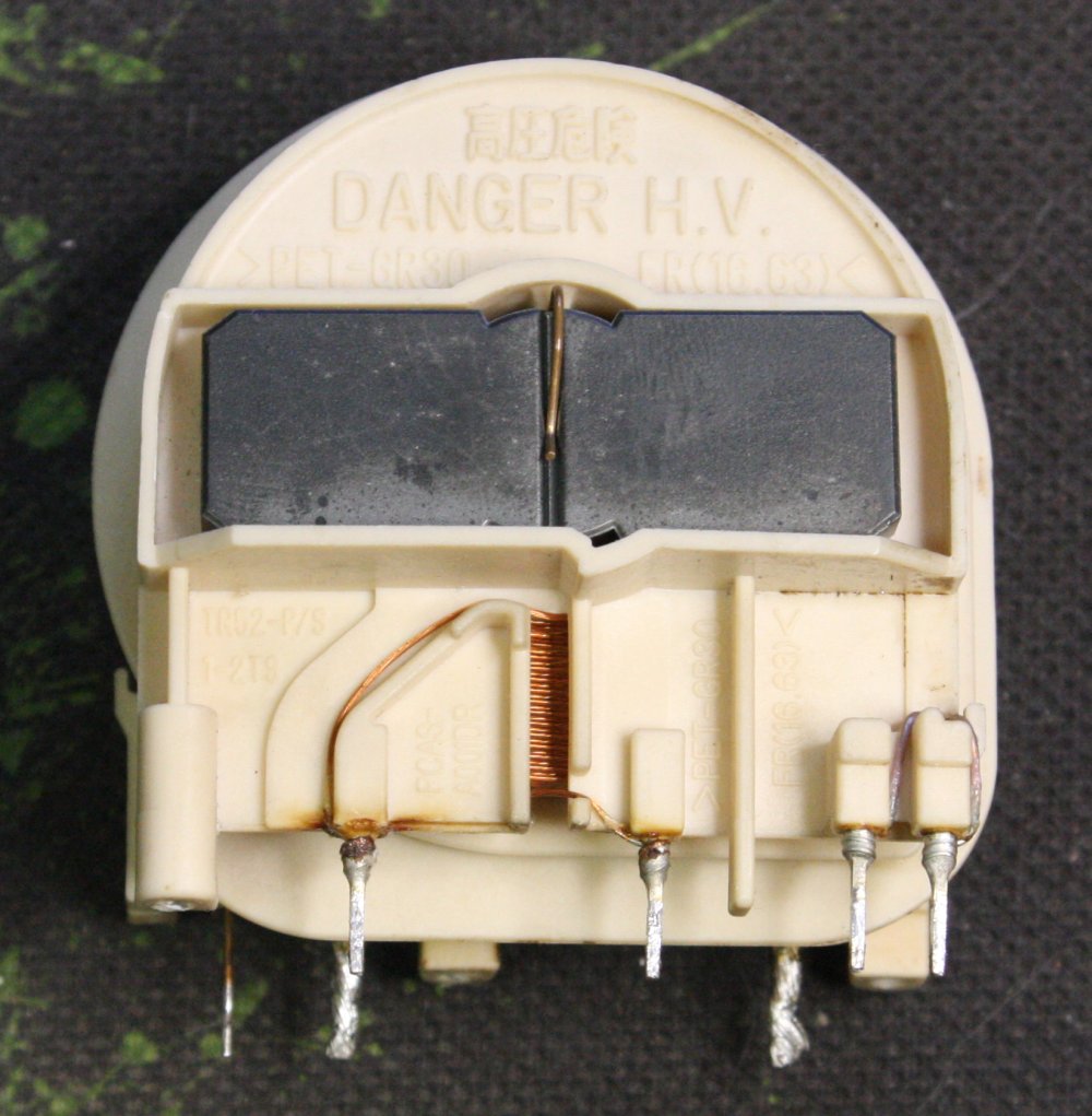 |
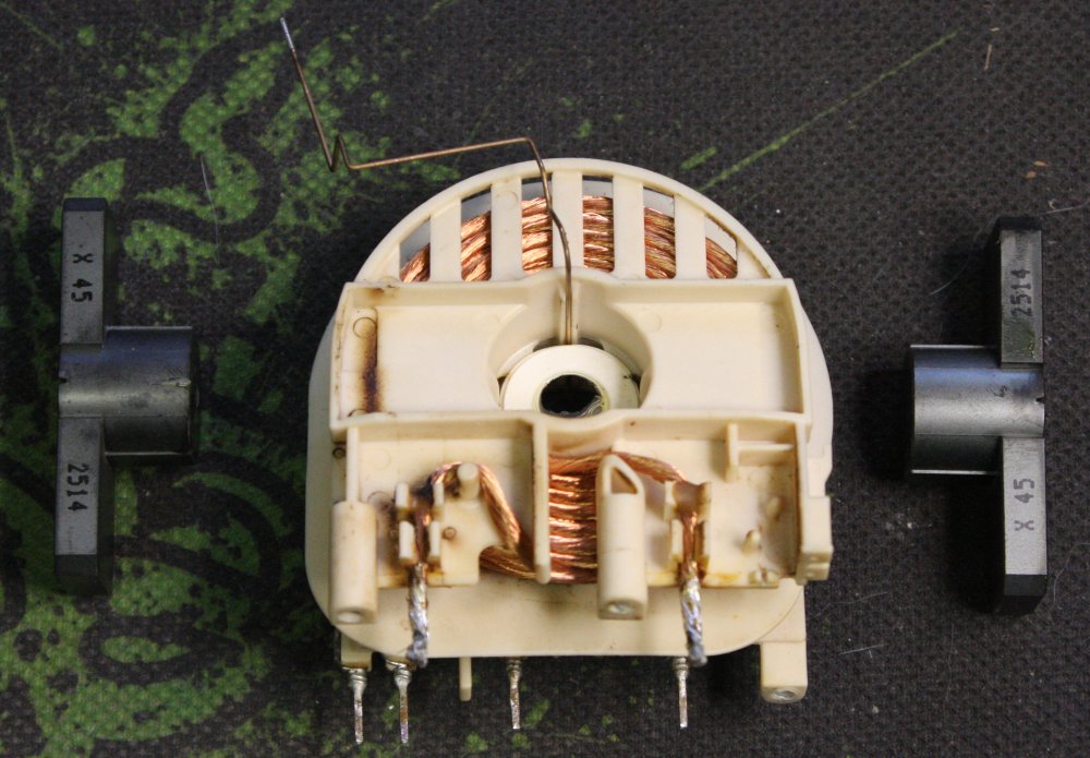 |
Removed heatsink and transformer, cleaned the inverter PCB and the removed parts.
This transformer is really interesting. For one thing the magnetic circuit is more air-gap than ferrite. It's almost the simplest case of an air-coupled pair of coils, with some permeability enhancement via the ferrite T-pieces.
Both primary and secondary are litz wire. The primary is obviously so, the secondary not so obvious until you examine the wire closely. It's formed of many fine strands embedded throughout a tough translucent material. Not a bundle of cores inside an insulating sheath. The binder material also acts as a soldering flux when heated, making it unnecessary to strip the ends for soldering. Not that sheath stripping would be possible with the distributed wires.
Even better, the transformer allows both the primary and secondary wires to be unwound or added to easily.
The circuit is clearly a resonant converter — there is a large capacitor in parallel with the primary coil.
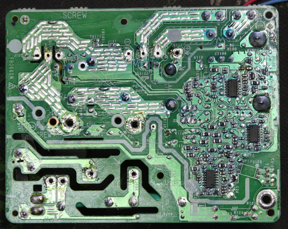 |
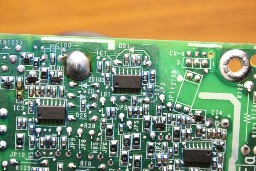 |
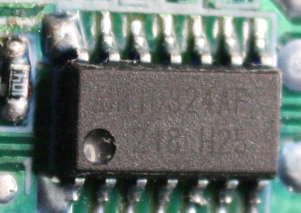 |
On this board control is by 3 small identical-looking SMD chips. Only there is a thin blue-ish conformal coating which makes the part numbers invisible.
The coating rubbed off easily enough with IPA, but unfortunately the chip numbers were either faint/non-existant originally, or they mostly came off with the IPA too. Two are only partially readable under magnification and getting light angles just right, while the third IC is completely blank.
It's maybe a BA10324AF: Quad ground sense operational amplifier. Fingers crossed they are all the same part number. The package molds seem identical, so it's likely. Tracing out the circuit will reveal if they have common pinout arrangement. In which case the effort will be worth it - a 1200W HV resonant controller using plain op amps? Excellent.
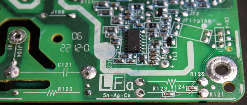 |
This was quite a surprise and an education. I've been out of professional electronics design for over a decade, and so managed to avoid most of the ROHS (reduction of harmful substances) production dramas. Which were probably the final nail in the coffin of Australian electronics manufacturing, outside of very high cost niche markets. Not worth going into the horror stories told me by operators of local PCB loading and reflow soldering factories back then, about the ridiculous operating costs and 'mishap cost risk' of production lines that tried to be ROHS compliant. As opposed to competing Asian manufacture, where nobody gives a damn about solder purity standards, and there are no profit-killing government fines and solder bath reload costs for trace impurities. Being more than a little cynical, I always thought the ROHS thing was intended from the outset to kill off Australian electronics manufacturing.
Anyway, see that silk screen logo "LFa" and "Sn-Ag-Cu"? That means the solder used is (claimed to be) a tin-silver-copper alloy. It melts fine with my old Weller with a '7' tip (700 deg F.) It does look a little more silvery and matte than tin-lead solder. But I'm amazed... There wasn't any skimping in solder quantity with this board. All major size joints have a lot of solder. I wonder what the silver content is?
Discussion here: http://www.eevblog.com/forum/chat/silver-solder-on-consumer-pcbs-really/
Also see https://en.wikipedia.org/wiki/Tin-silver-copper
Well huh. This is going to get interesting once the silver/gold price suppression cartel loses its grip on the market and silver price returns to its historical buying power. Can't solder electronics with paper silver certificates.
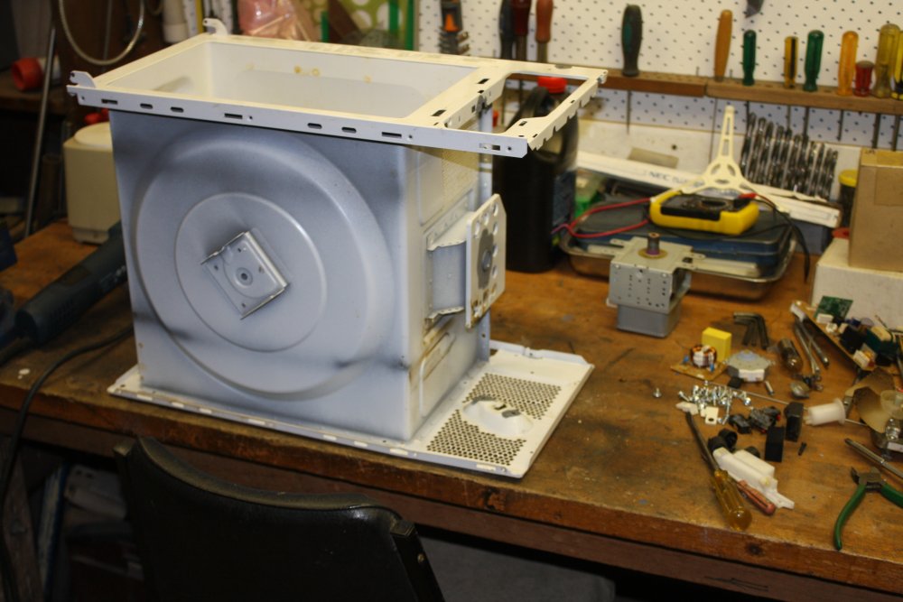 |
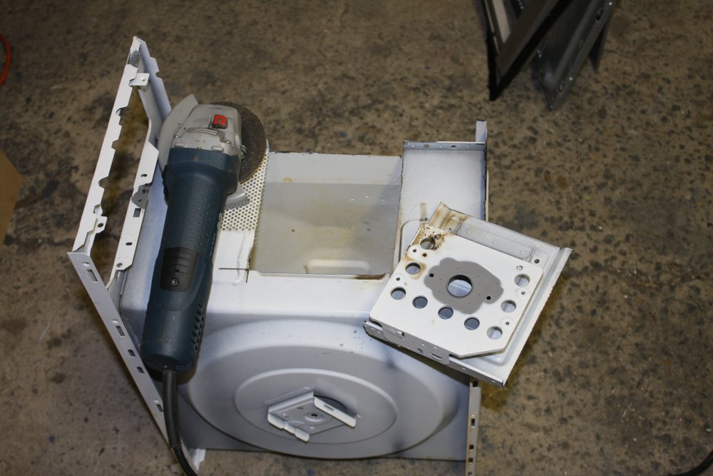 |
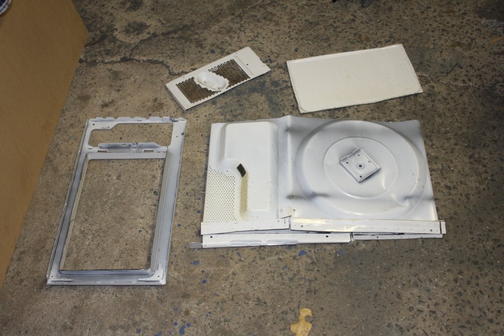 |
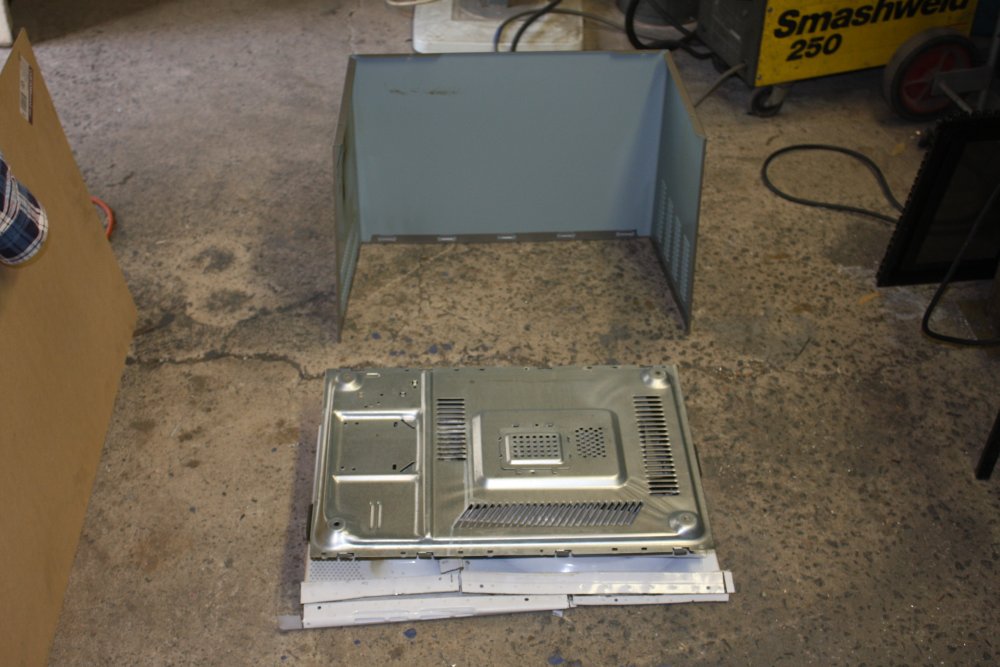 |
I already have three working salvaged inverter microwaves. Don't want any more. So this one's case gets size reduced for the recyling bin.
Strangely, I never found any kind of model number on this oven.
20151228 Cameras as light sources
While clearing out stuff for his move to Brisbane, my son asked me if I wanted a broken Canon EOS top frame. I'm not sure what model it was, but one of the fairly high end ones. It was junk due to the alloy case being cracked. Thinking it would be interesting to disassemble it I accepted. Here's the resulting pile-o-bits.
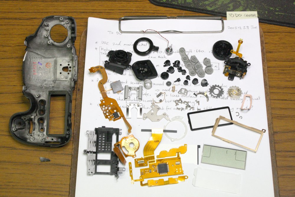 |
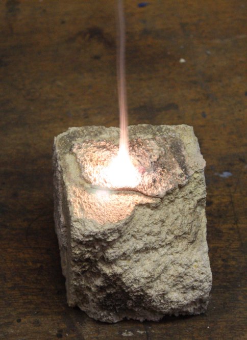 |
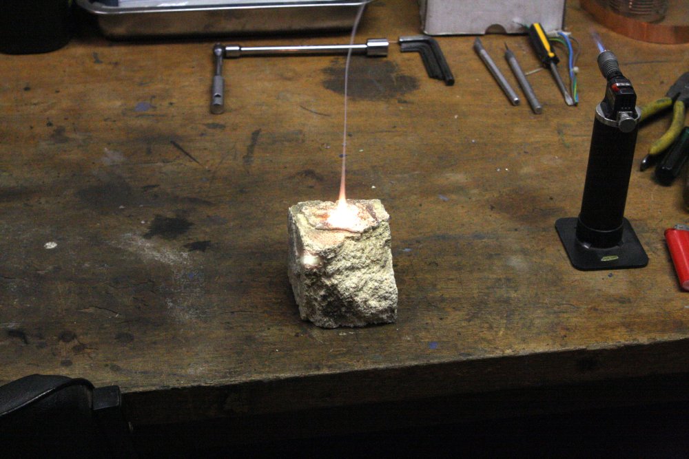 |
The bare frame casting felt remarkably light and stiff. Definitely not your usual diecast aluminium-zinc. More like a magnesium alloy. Hmm... how much magnesium?
Ha ha... quite a lot. I snapped off a tiny piece (lower left in 1st pic), and heated it on a firebrick. Wow...
I wonder how many Canon high-end EOS owners know they are holding a very respectable emergency flare? Or if they had two, and an urgent need for extra scene lighting, they could just set one of the cameras on fire.
20160103 Atari Asteroids Archaeology
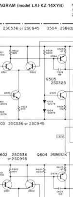 A while ago a guy attempting to restore an old Atari Asteroids arcade game, asked for assistance on the eevblog forum.
Back around 1980/81 I worked as a service tech on those and other arcade games. I knew I still had a folder with the game board schematics, XY monitor service manual, and more. But could I find it? No. I did find some other docs from that time, including some related to the Asteroids game. I scanned and posted those in the thread.
A while ago a guy attempting to restore an old Atari Asteroids arcade game, asked for assistance on the eevblog forum.
Back around 1980/81 I worked as a service tech on those and other arcade games. I knew I still had a folder with the game board schematics, XY monitor service manual, and more. But could I find it? No. I did find some other docs from that time, including some related to the Asteroids game. I scanned and posted those in the thread.
Then just yesterday I accidentally found my Asteroids folder, misplaced in my workshop files under a wrong topic. Sigh. Anyway, today I scanned the X-Y monitor service manual, and some other notes I found. The files are here: http://everist.org/archives/scans/Atari_Asteroids/.
That took all day. Not the scanning; that was done in half an hour. What takes ages is the cleaning up in photoshop, stitching together large sheets, converting print-screening shaded areas to flat colour, removing blotches, scaling, cropping, compressing final images to minimal file size, and bundling the results into a neat html file.
20160106 Filling that rack
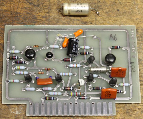
Fixed one visibly obvious fault (leaked 100uF 30V wet-slug tantalum cap) with a bodge of an electro and two tantalums (measured value is what's supposed to be there), then tried powering it up. It's alive, but as expected it has multiple faults. Including no oscillator output. Not going to dive into that now, so in the rack it goes.
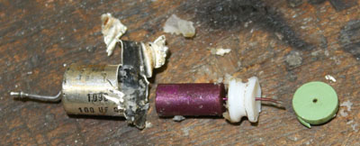
Out of curiosity I cut open the leaked tantalum cap. It was still about 95uF despite the leaking, but was corroding nearby tracks so it had to go. The purple colour of the sintered tantalum slug was a surprise. So that's the colour of the dielectric layer tantalum forms? The leadout wire on that end is purple too, so I presume it is also tantalum.
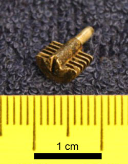 There's one small mystery remaining about the HP 4815A. When it arrived here from the USA and I opened it up to investigate replacing the broken right side frame handle, there was a small part loose inside. It's the vane set from a tiny variable trim capacitor. I assumed it had come off one of the boards in the 4815A, and kept it in a little ziplock bag with all the other screws and bits from disassembly.
Now I've had a good look at all the boards, and also inside most of the shielded compartments, I haven't found any such trimcap at all, let alone any missing the movable part. So where did it come from? It's probably a 'drop-in', but it boggles the mind that some 'service centers' could have bits of stuff flying about the room and falling into open equipment.
Just in case it's from some part of the machine I haven't yet inspected, I'll keep it.
After mounting the 4815A in the rack there's one empty 3U slot left. Since I'd found a bundle of those oversize rack brackets, I decided to also make brackets for my Tek R5030 scope. This scope is a fine antique, but needs quite a bit of work. Some parts for that are currently in the mail. For easy access I'd like to have this scope in the rack too. So, rack filled.
Sure does make a difference, not having all those things lying around on the floor and in odd corners.
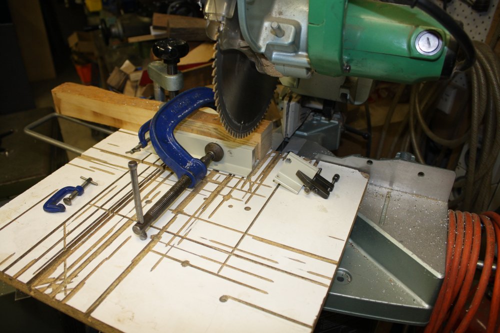 |
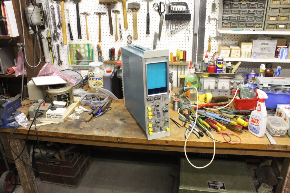 |
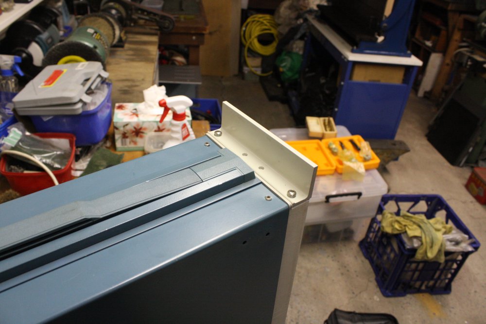 |
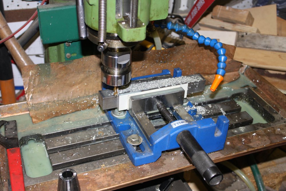 |
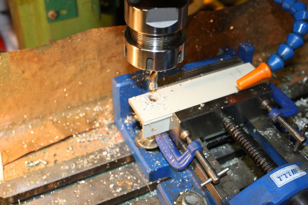 |
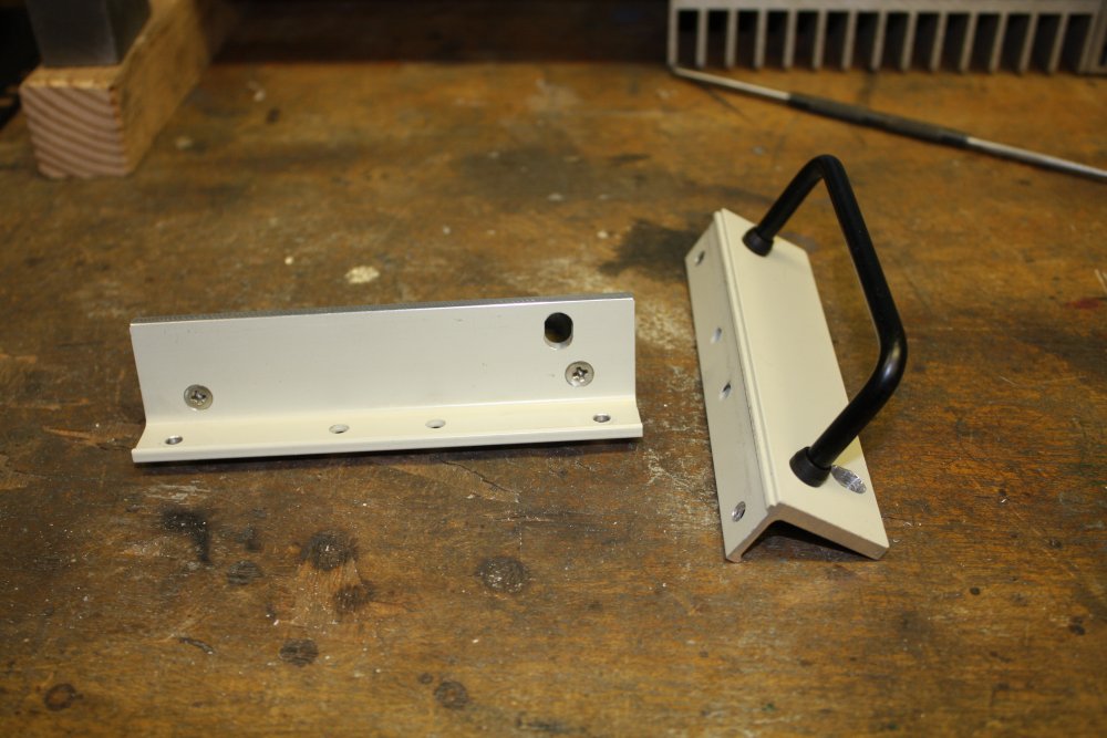 |
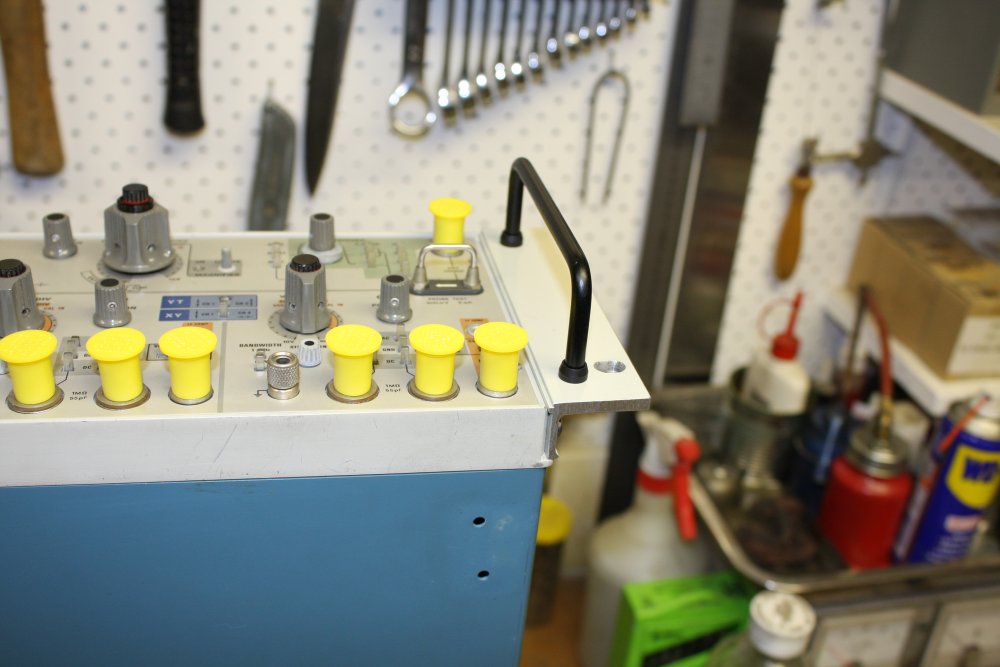 |
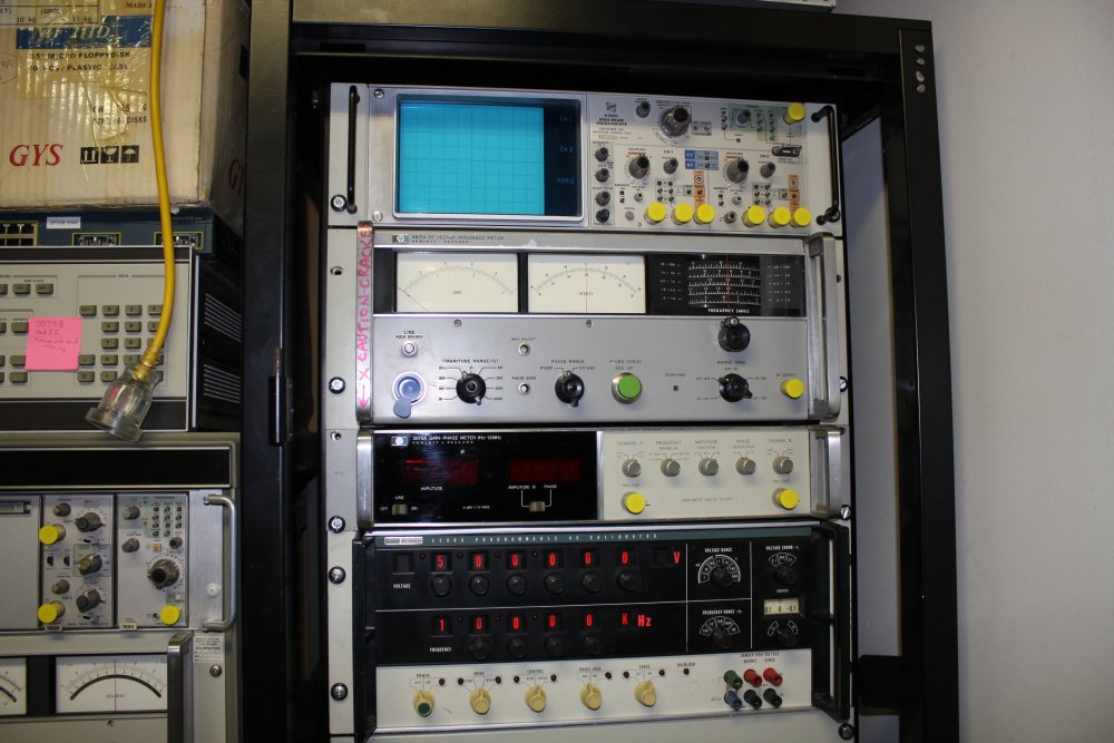 |
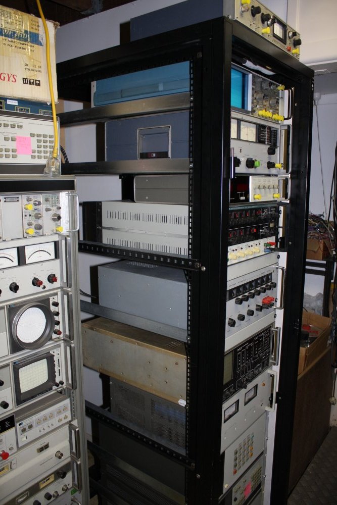 |
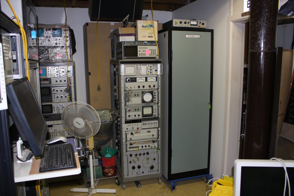 |
The rack's name is Phobos. From the game Doom; level "Knee deep in the dead".
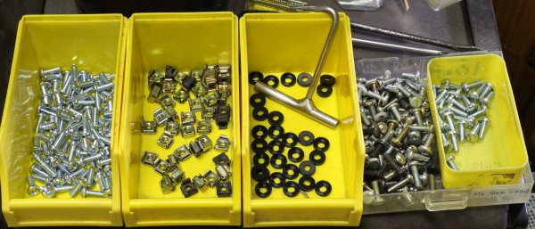 Oh, and I finally got around to buying some phillips head M6 rack screws, instead of the mostly slot-head scavenged dregs I've been using. So much easier.
Darnit, I've been wanting to get that vacuum pump back together, and the mech-workshop bench is free now. But one more thing first...
20160108 HP 54120B Power Supply Repair
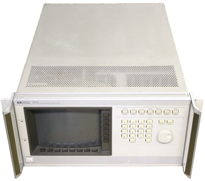 Earlier I mentioned a HP 54120B Color Digitizing Oscilloscope Mainframe. This is the main part of the HP 54121T 20GHz scope system, of which I have two working. My major long-running project (the vacuum system is a part of it) absolutely requires a GHz capable scope, which is why I have two. These were made in the late 1980s and were extreme high-end gear then, though the mainframe looks very generic — see at right. (Btw I much prefer that plain look over modern excessively-styled stuff.)
The 54120B has long been out of support by Hewlett Packard (who don't even exist anymore, as such.) Hence the need for a spare since contemporary GHz-scopes are vastly beyond my financial means. I'm trying to put together a somewhat more modern equivalent capability system, starting with a HP 83480A digital communications Analyzer/scope, but so far haven't found any affordable plugins for that mainframe. Turns out those are still compatible with current model high end Agilent/Siglint scope mainframes, so the prices haven't dropped enough (for me.)
In 2014 one of my 54120Bs developed an intermittent fault. At that time I didn't have schematics of the boards and all I could do was pin it down to one board by card swapping with the other good unit. Swapping cards between my only two working units didn't feel like a safe situation, so in Feb 2014 I bought a third 54120B mainframe (without the sampler head) for $75 as spare parts. (Plus shipping from the USA - a lot more.) It was ebay-listed as 'powers up' but the seller informed me that was a mistake - it no longer powered up. Hence the low price accepted.
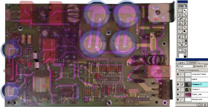 When it arrived I confirmed all the cards worked in my other units (good!) and there's something wrong with the power supply. I didn't have a schematic (it's not in the 'service manual'; thanks HP), but it's not a terribly complicated board and I thought it would be easy enough to fix. Besides, any circuits I traced out would be useful for all three identical mainframes. So I started tracing the circuit of the main supply card. That involves things like the photoshop layered view of the PCB at right (in much higher resolution) and hand drawing circuits bit by bit. With lots of error checking, some mistakes and doing sections over again. It's a slow process.
There are three power supply cards: Primary, Digital and Analog. The Primary has no connections to the system other than cables to the CRT display, the Analog and Digital supplies, mains-in, and the front panel power switch. The system didn't appear to power up at all, so I'd decided to start with the Primary supply card.
There's only one IC on the board, obviously a switch mode controller. To reverse engineer the board to a schematic, it's necessary to find technical data on all the non-simple parts. This IC turned out to be something of a mystery. It's manufactured by Exar, but only has a HP internal part number ( 1826-1120 ) marked. There's an amazing lack of online information on this part. Not listed in any HP equivalent parts lists. No data sheet, not even a block diagram. Some hints online that it may have been 'secret' due to use in a missile system. Almost all the online search hits for this part number are from other people discussing not being able to find anything on it.
At that point I paused on this repair. Which meant that now I had another (large) piece of equipment sitting in pieces. In this case on my main electronics workbench, which along with the several other stalled repair projects there, completely filled the bench space.
A while later, in June 2014 I found a source of PDF full schematics for the 54120B mainframe. Including the power supply. As usual with PDFs they have many flaws, including foldout sheets being broken into pieces, skewed scans, blotches, fax-mode jaggies, etc. Plus unbearably awkward access due to being stuck together in one huge linear document that makes finding individual sheets very tedious. I hate PDF, PDF readers and badly scanned technical docs wrapped as PDF sooooo much. Even more than tantalum capacitors.
I was busy with other things, didn't return to the HP 54120B, but did at least clean up the power supply schematics into a more convenient format. See: zip-file or HTML. (No the schematics are not tiny, click the thumbnails.)
Now it's time to have another go at repair.
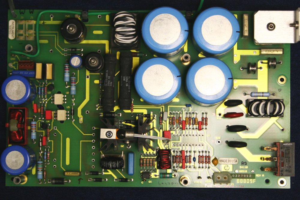 |
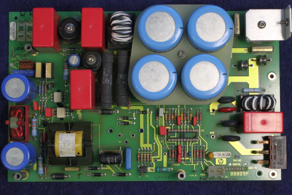 |
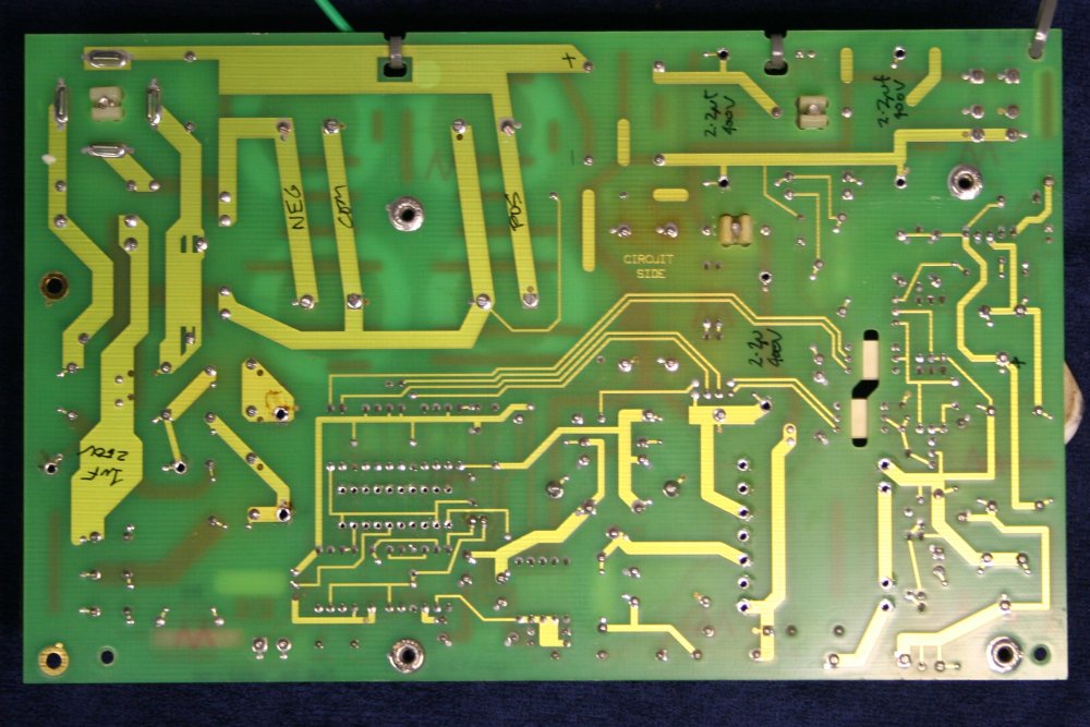 |
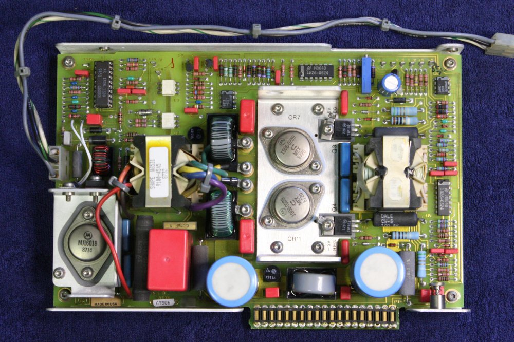 |
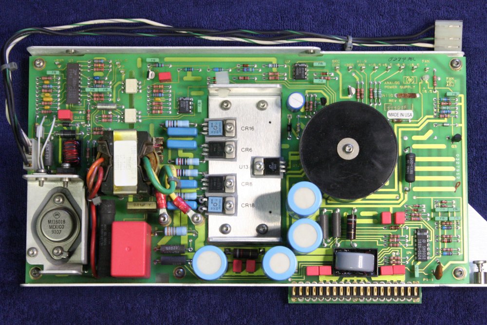 |
1 - 3. During efforts to derive the circuit diagram I had desoldered several components from the Primary Supply PCB, to allow following tracks. With components like the main transformer, drive transistor and control IC removed, it's possible to do some functional testing that can't be done with them in-circuit. So before soldering them back in, I would do those tests just in case they turn up something. Rather than solder the IC in, I put in a high quality socket.
4. Digital Supply Board.
5. Analogy Supply Board.
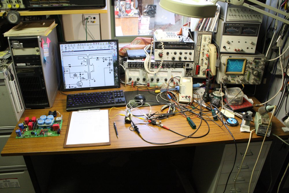 |
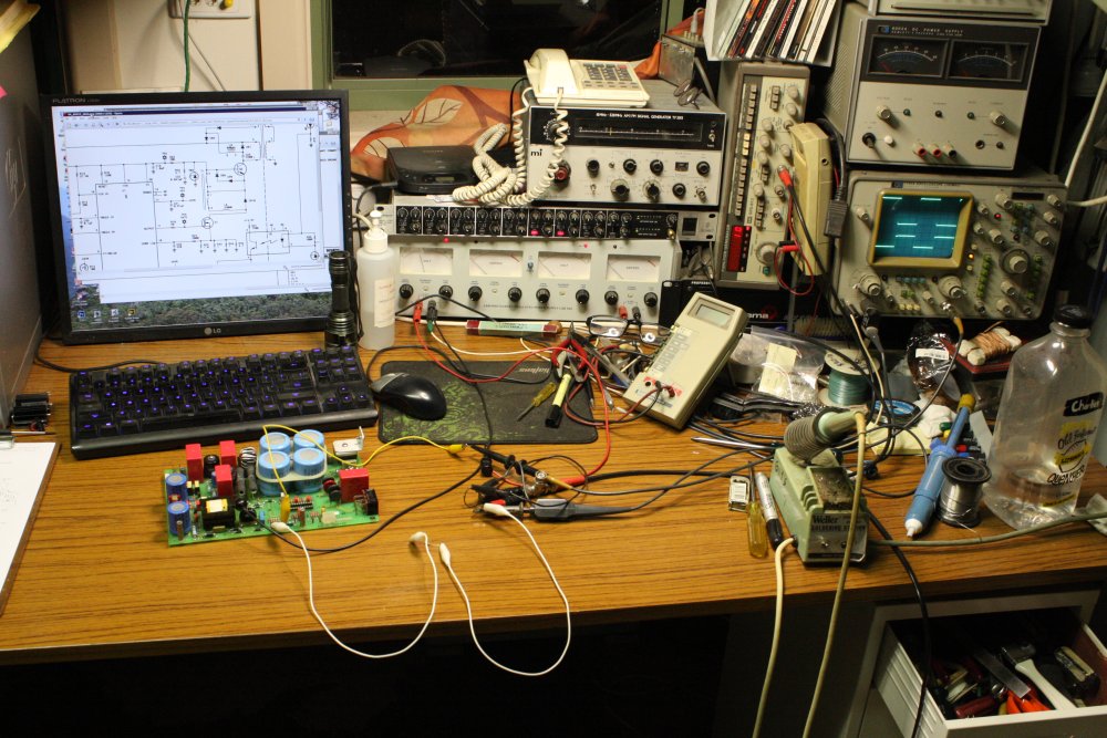 |
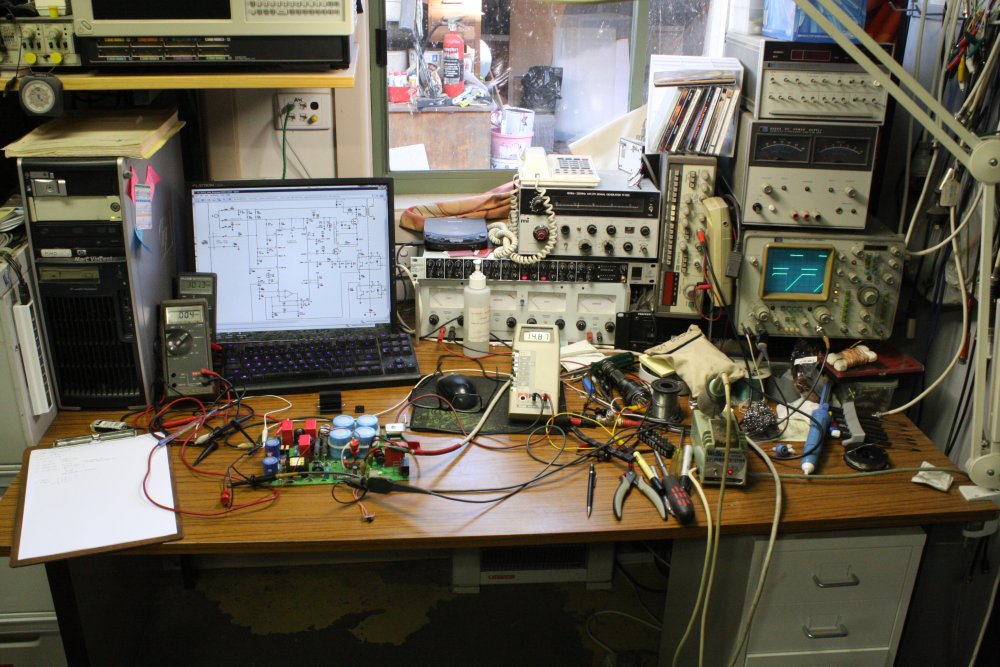 |
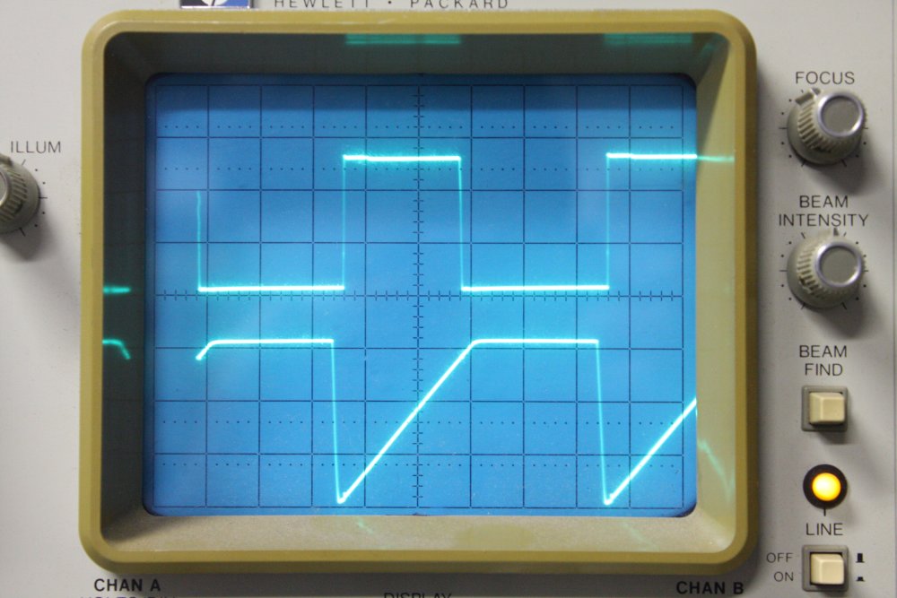 |
- The power transformer T2. Feeding a 4Vpp 10KHz sine into the primary (pins 5-7), other windings are: 1-2: 1.25Vpp, 3-4: 1.25Vpp, 10-9: 0.53Vpp, 9-11: 0.53Vpp. No sign of shorted turns, or shorts between separate windings.
- The IRFD120 drive FET, Q1. Feeding the Gate a 0 to 10V square wave, with a resistive load on the Drain, it switches as expected. Also with a floating Gate I can make it switch with my fingers nearby, so its Gate insulation is good too.
I had also looked at the protection RT3. Another proprietry HP part, listed as "thermistor - switching resistance:100". It measures 120 ohms at room temp, and only dropped slightly to 117 ohms on heating somewhat with a soldering iron on the tab. I presume it's supposed to change resistance abruptly at some temperature limit, but I'm not game to heat it a lot to see. I did isolate the same part on the Digital board, and it behaves the same.
- Powering up the board (via variac and isolation transformer), all components in except the main drive transistor. The control IC appears to be running correctly.
Since there's no data available on this chip I'll give measured details here, in case they are useful for someone else servicing one of these boards.
- Scope traces: upper: U1 pin 11 "Gate" output 12Vpeak. Lower: U1 pin 6 "FF/RR-CR" zero to 6V, 25 uS period. The ramp duration varies with the +300V level. Less V ==> slower rise. The duty cycle is high because main transistor Q2 is not mounted, so the chip is maximizing drive.
In Standby mode (front panel 'power' switch closed) U1 pin 6 stays at 6V. So the front panel switch just disables the Primary switching regulator to shut down the machine.
Other values, all with mains input adjusted for the "+300" rail to be 300V:
U1 pin 20 "VZ" (TP2) = 14.87V. This is clamped by U1, from the +150V main caps rail via 10K resistor R3.
U1 pin 15 "Reset" = 1.478V.
U1 pin 19 "VIN UV" = 6.28V
U1 pin 4 "VBULK UV" = 8.41V (in Run)
U1 pin 5 "VBULK OV" = 3.61V (in Run)
Incidentally notice the +300V and +150V rails are always live while mains is applied (front panel 'power' switch has no effect here) and there are two resistors always drawing current from the 150V rail. 10K R2 just to light a LED, and 10K R3 to power U1. So this supply always dissipates around 4.5W while mains is applied. Only turning off the rear panel circuit breaker stops this. No standby power is supplied to any of the system boards, so there's no purpose to this wastefulness I can see, other than perhaps keeping the instrument warm to prevent condensation.
Anyway, I've had two of these 54120Bs in racks, with power applied, for maybe two years. Oops. Turned them off fully now I know. The cost was about: 10W for 2 years: 1 yr = 8760Hr, 2yr = 17520Hr. x10W = 175.2KWHr. At 20c /KWHr = $35.
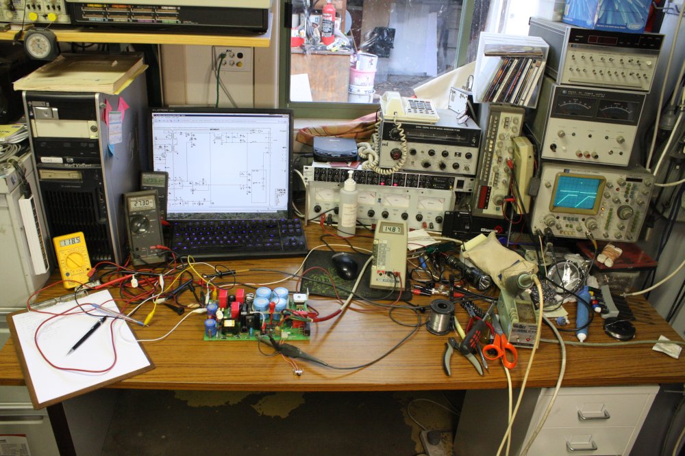 |
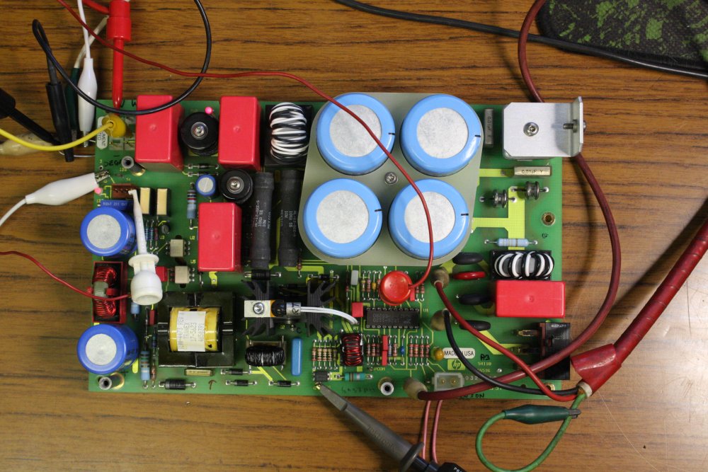 |
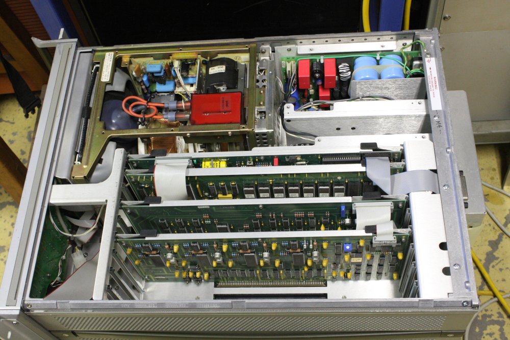 |
1 - 2. Running the board with everything mounted. Incidentally there was a component side trace running under the main transistor heatsink, that wasn't at the same potential as the heatsink. Nothing between them but the heatsink anodizing and the solder mask. Not something I like to see, so I insulated with some Kapton tape.
The supply is working fine. Drive duty cycle is very low, since there's no load on the +120V output (that powers the CRT monitor.) Note that with no +120V load, the "+25V" output that provides the DC "VCNTL" power-up signals to the Digital and Analog supply boards is insufficient to enable them.
3. Mounting all the power supplies back in the mainframe. Wishfull thinking - maybe it all works now?
Ha ha, no. It does power up the CRT (can hear it, and see a colour blob on screen when powering down again), but nothing else. The operating LED on the Digital supply blinks briefly on power up, while the Analog supply LED has no activity at all.
So, next the Analog board. Not to mention figuring out if there's some interlock between the Digital and Analog supplies via the system motherboard.
Annnnd... there isn't. Here are the motherboard schematics extracted from PDF, into a zip-file or HTML.
See Sheet 2, J1 & J2, and the power supply schematics. The Digital supply has a "PSFAULT" input but on the motherboard it is not connected.
So both these supplies should work with just the +300 and "VCNTL" enable signals applied. Which I can easily do on the bench.
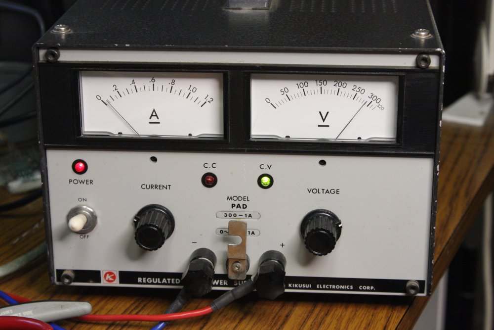 |
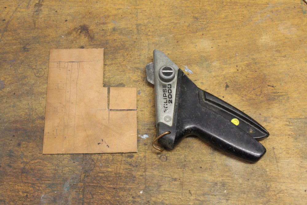 |
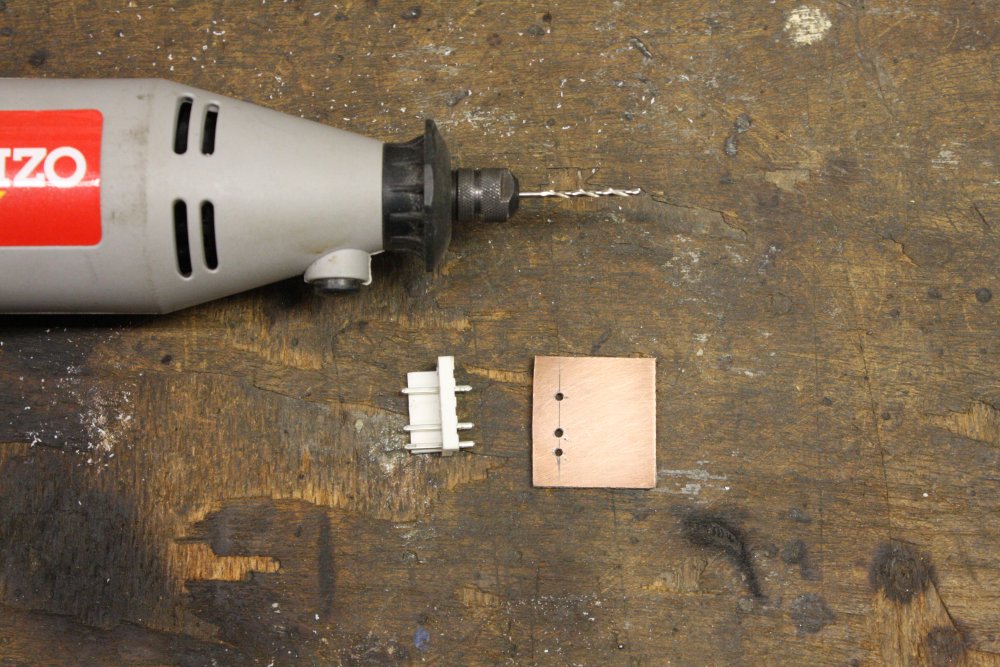 |
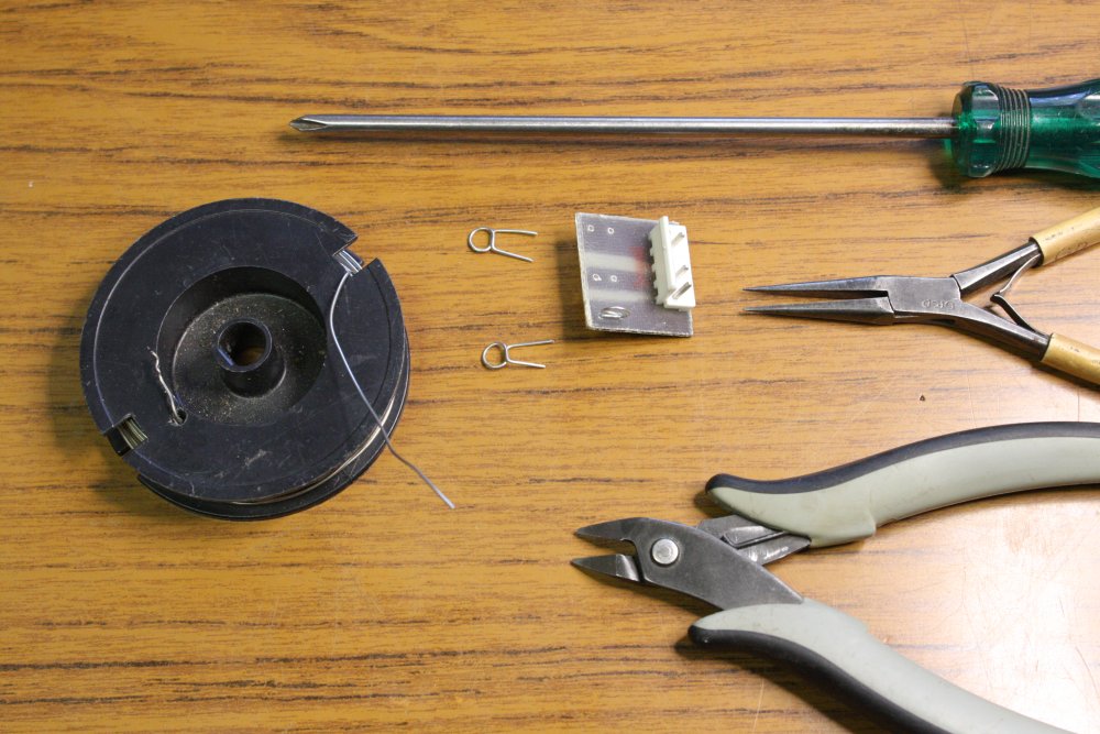 |
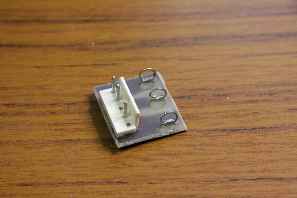 |
Well, except that I don't like the idea of a loose clip-lead tangle carrying 300V DC. That power supply in the first pic should be treated with all respect due to 'death on a desk.' So to make a less death-risk connection to the input cable of the power supply I made this patch connector. Then hard-wired it safely to the power supply.
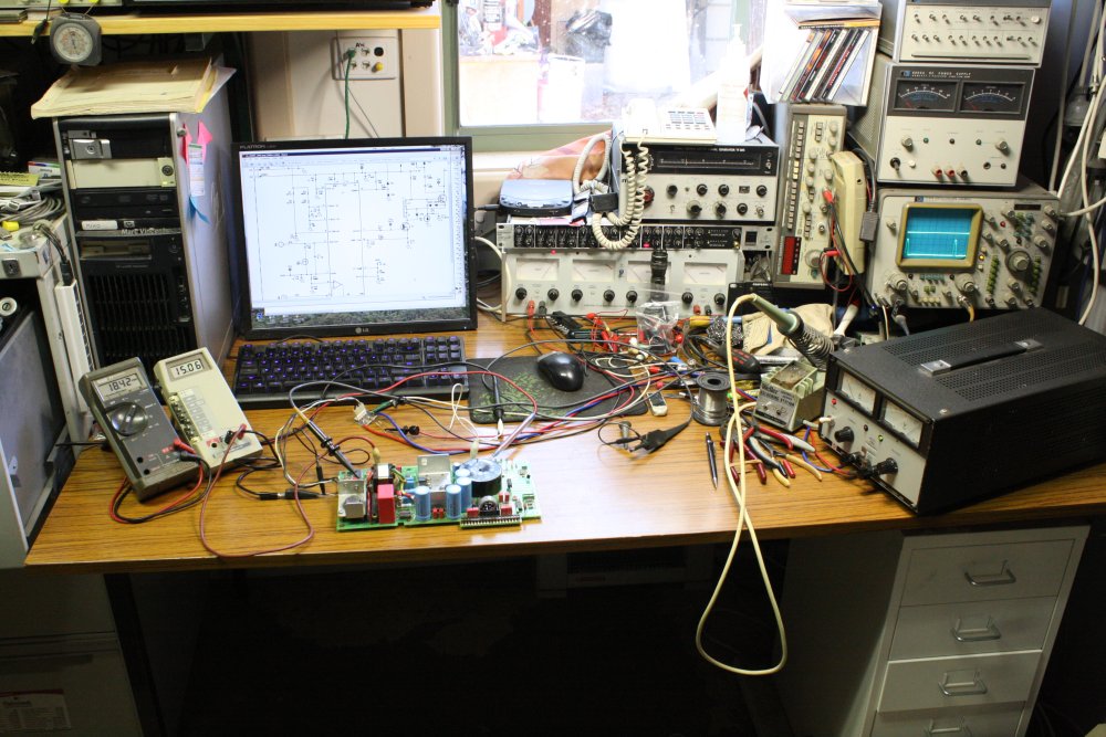 |
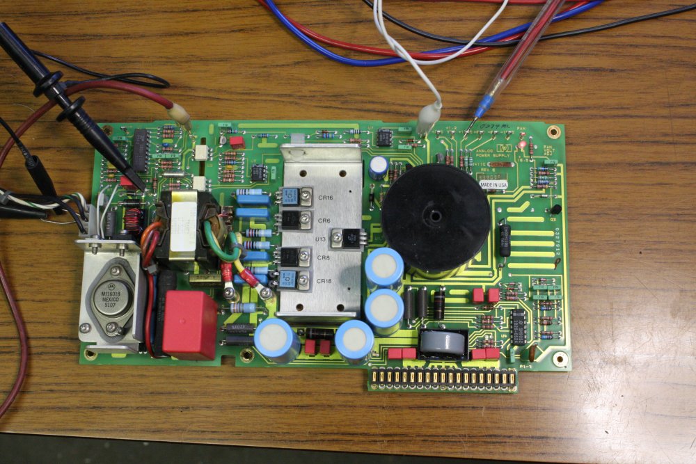 |
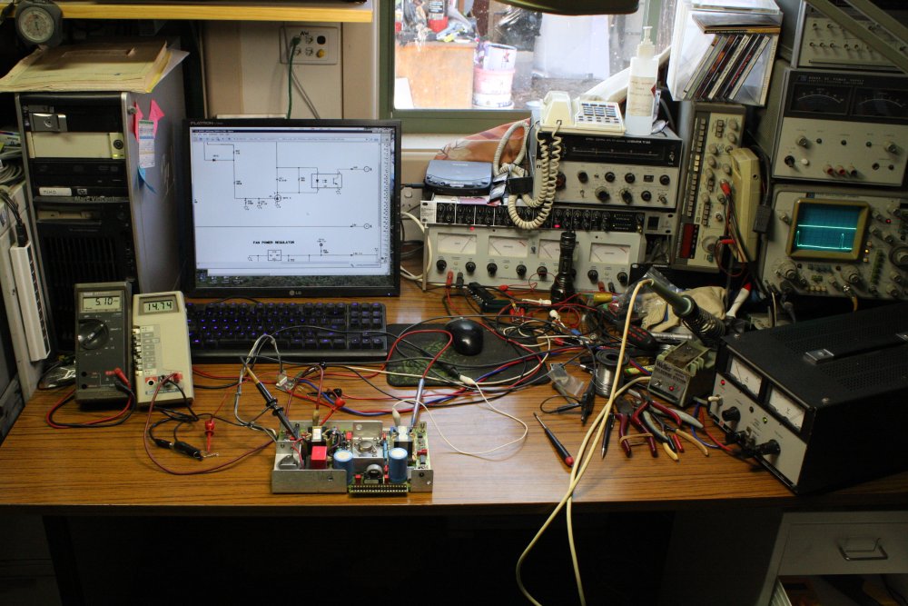 |
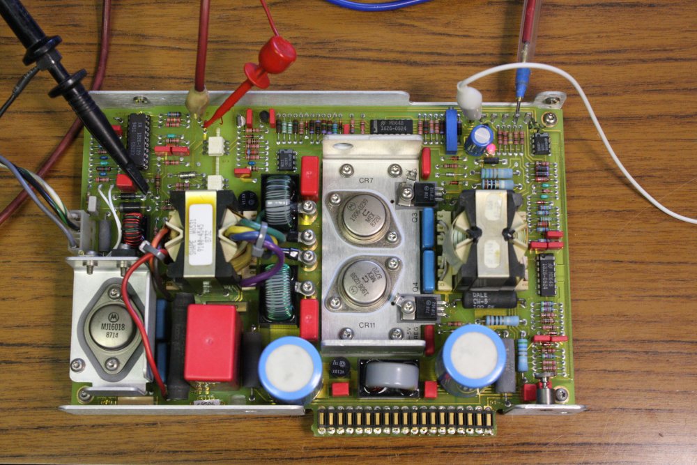 |
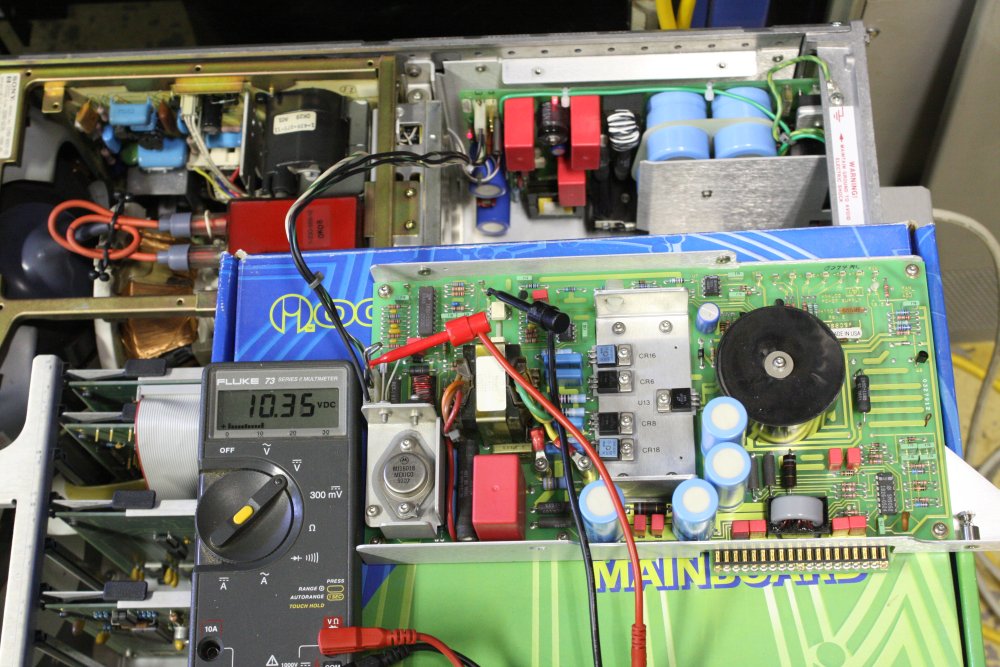 |
Well huh. The Analog supply runs fine like this (pics 1 & 2.) So does the Digital supply (pics 3 & 4.)
If it was just one that worked on the bench but not in the machine, I'd start looking for a shorted rail in the mainframe. But both supplies? No, that's not likely. And since the only thing in common here is still the Primary supply, and that runs fine too... there is only one small bit of common circuitry I didn't yet check. Let's have a look...
Pic 5 is the analog supply, sitting on top of the machine and powered via its connector from the Primary supply.
Should work, right?
No, it doesn't! Cool, now we're getting somewhere.
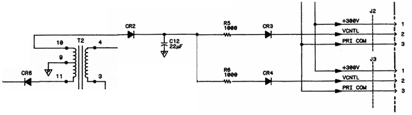 It's not running because the VCNTL input, which should be around +25V via a 1K resistor on the Primary supply, sourcing about 10mA to the Analog switchmode regulator IC's Zener clamp to +14.5V, isn't really there. The VCNTL line coming into the Analog board, which should be about +14.5V, is only 10.35V. And at power-up, it ramps up quite slowly to that voltage.
So it's something in here. Looking at VCNTRL with a scope it has no perceptible ripple, so C12 is not suspect. (Ha ha, spot the logical error I made here. See below.) It's affecting both slave supplies so it isn't R5, R6, CR3 or CR4. Looking at you, CR2.
Hmm. Or I suppose there's still a possibility of something funny with the CRT display, resulting in the Primary supply not having enough load for the transformer to drive this little circuit properly. I don't think so (since I can see the CRT powers up, even though dark due to no graphics), but since I was intending to open up the other unit with the intermittent card anyway... I may as do that now. So I can swap a known good Primary supply board in here, to eliminate the 'bad CRT' possibility.
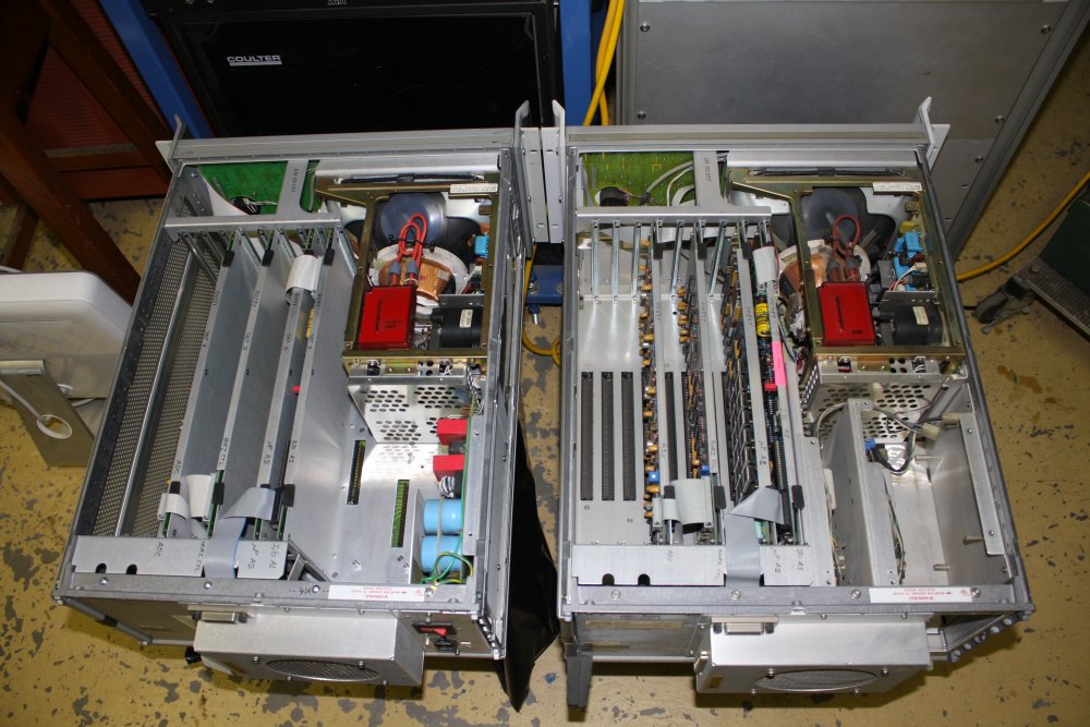 |
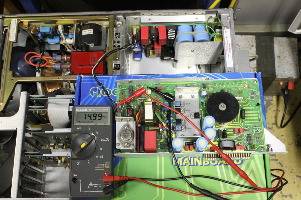 |
1. The unit I've been working on at left; at right the unit pulled from rack (with intermittent logic fault.) Already swapped the Primary supply.
2. With the known good Primary supply in the dead unit, the Analog supply powers up correctly. VCNTL is 14.99V, ie OK. So the CRT is not involved, and the fault is definitely on the Primary supply. With the good Primary supply and Analog and Digital cards back in the machine, it powers up and passes its self tests. Which is nice to see — I hadn't had this machine alive before. As a bonus the colour display is crisp. As opposed to being out of R-G-B convergence due to impacts during international shipping, which is common.
Unfortunately, doing a quick multimeter diode check of CR2 on the bad Primary supply board, it seems OK. But I have a working reference board, and can set up to easily switch between the two boards working on the bench, for comparison. They'll need to be running with a sensible load, so I measured the current draw of the CRT monitor: 337mA at 120V DC with the good power supply. Need a 355 ohm 40W resistor as a dummy load.
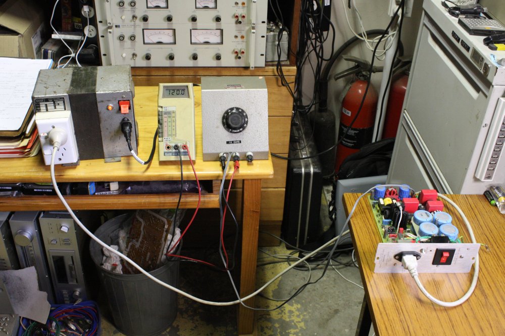 |
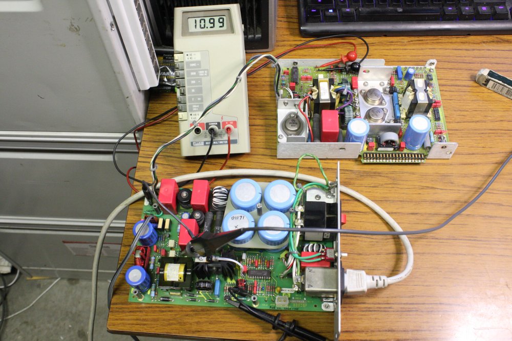 |
Like this. The gray thing in center of pic 1 is a big wire-wound rheostat, 1K total, set to 355 ohms.
Pic 2 is the test setup. Everything is plugged or clipped to the board, so easily swapped. This is the bad Primary supply, with its feeble 10.9V VCNTL output. Comparing the working to failed boards, the signals at anode of CR2 are:
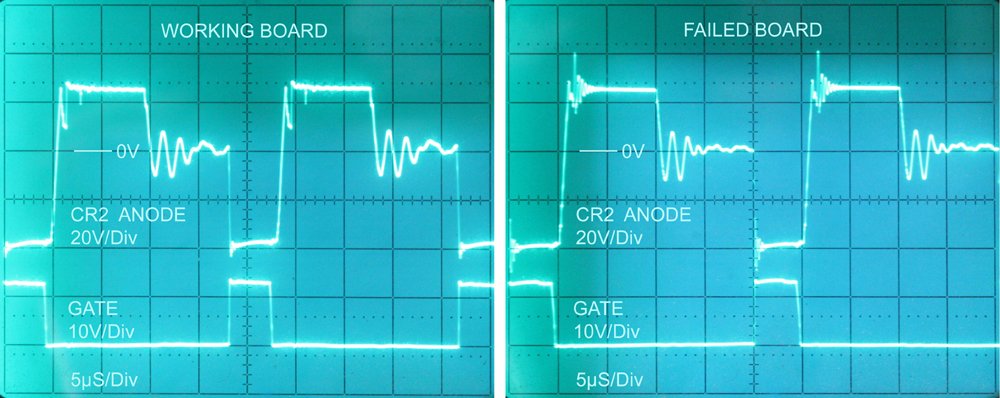
Curious. The only significant difference is that dip vs ringing at the top-leading edge of the CR2 anode signal. It's like... that diode is not seeing any pulse of forward current on the dead board.
Mystified, I pulled the diode off the board, and measured it again. It's fine. Again. Just to be sure, I swapped it with another identical diode on the board. No change.
But then what...? And the penny finally drops. Wait, earlier when I thought I looked for ripple on VCNTL, where did I probe that? Did I... Oh god, I did. I measured it at the test point on the Digital board.
Idiot. At that point it is filtered again by the 1K resistor on the Primary board, and the 1uF cap on this rail on the slave power supply board. I thought I was eliminating C12 on the Primary board from suspicion, but did no such thing.
All right... I pulled C12, and measured it. Groan. It's completely open circuit. 830pf instead of 22uf. Put a good one in, and it works.
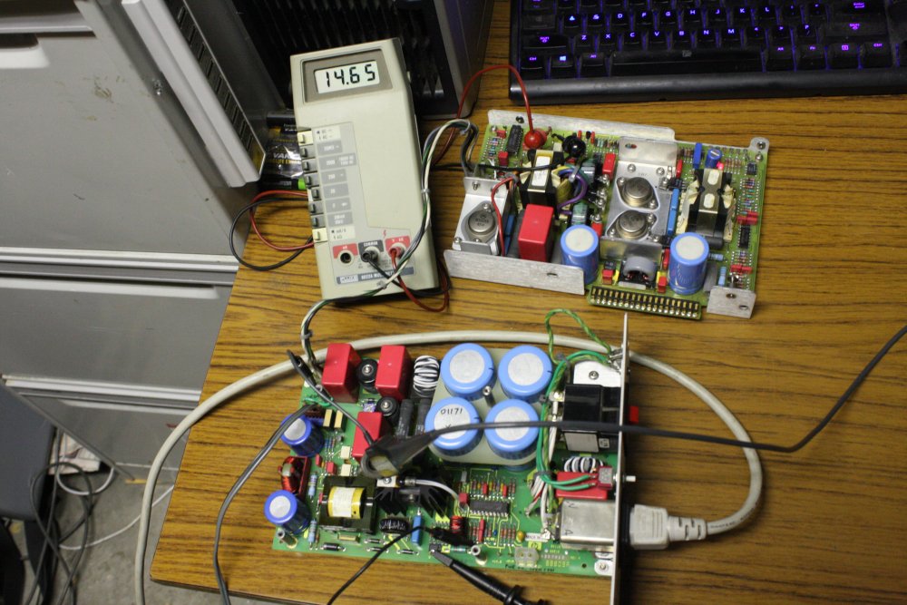 |
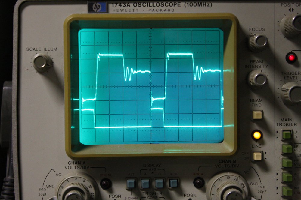 |
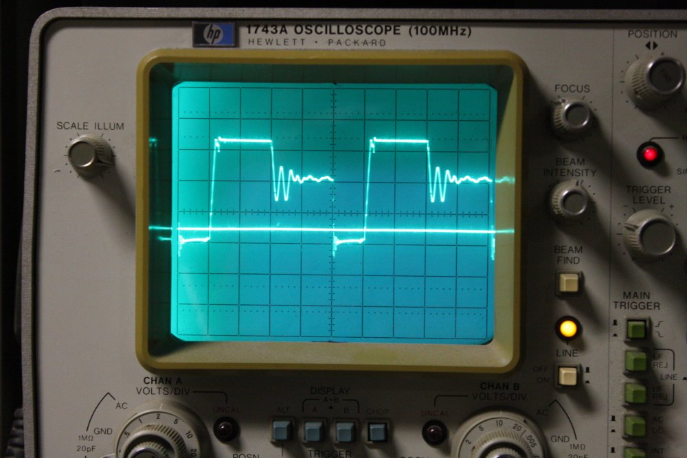 |
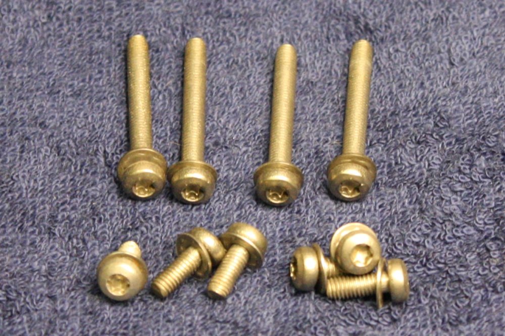 |
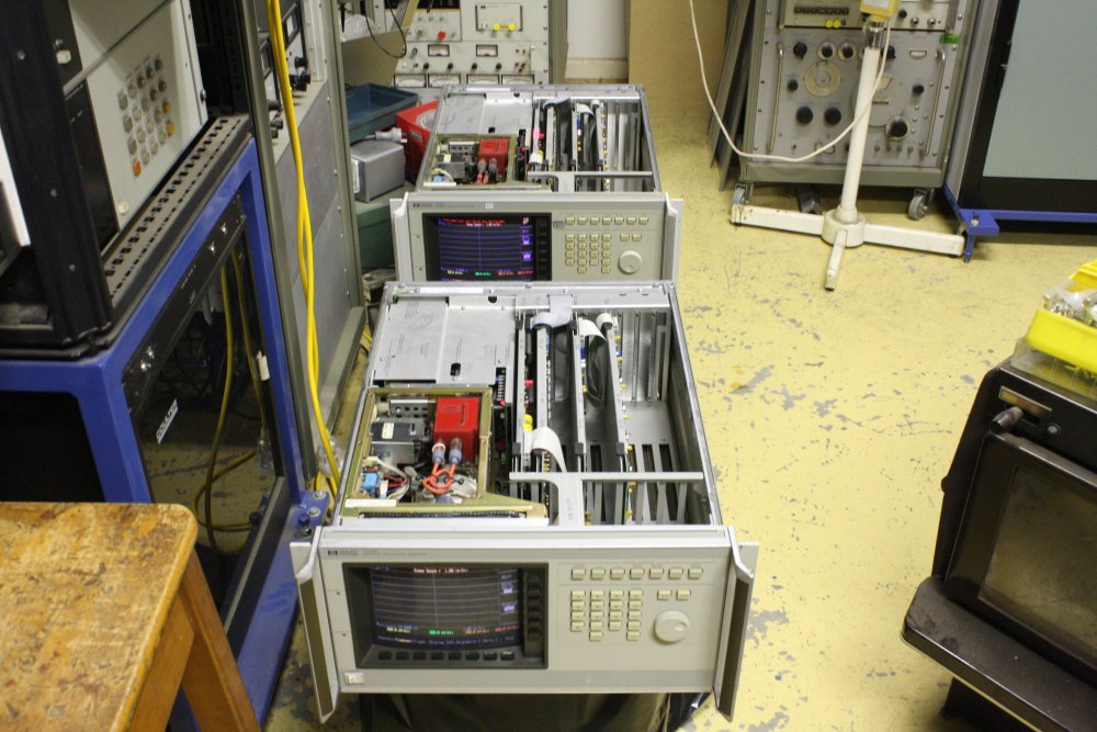 |
1. Victory pic. The previously dead Primary board now working.
2. Interestingly, quite a different behavior at the corner of the rising edge. I guess the ESR of C12 has a visible effect here.
3. Scope settings unchanged, but the lower trace is now showing the voltage on the cap. Which happens to be approximately +25V, as the schematic says. Though that label is on the transformer winding output, which is silly.
4. Speaking of silly, check out the screws they used throughout this machine. Someone must have told the engineers they didn't need to worry about cost at all, so they chose the very best quality, esoteric screws they could find (in the 1980s, in Imperial threads USA.) All the screws everywhere in the machine are metric, stainless steel, Torx head, with captive dome spring washer. They're very nice, but I'd love to know how much they added to the price back then.
5. Victory pic. Both units working. Then the mess tidied:
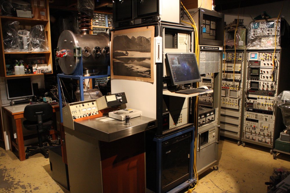
20160107 Seeking Unobtainium
When beginning to try again to repair the HP 54120B Power Supply I'd also had another look around for anyone selling that HP-numbered IC 1826-1120. And this turned up:
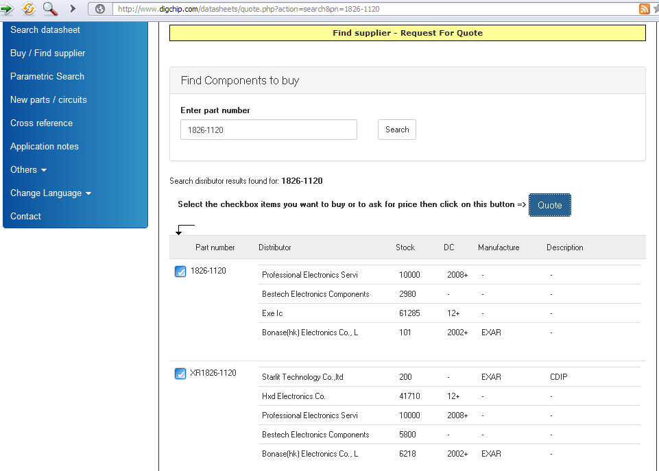
Well it's curious that an obsolete part made in the 1980s through early 1990s, for which there seems to be no information on the net, would have such high stock quantities sitting in Asian warehouses. And with much more recent Date Codes too, isn't that strange? Oh well, maybe it really is some common well-known part, but there's no trace of a connection on the net. Somehow. Not to pre-judge anyone, based only on anecdotal stories of Chinese fake parts.
I thought an experiment would be in order. In which I'd either end up with some genuine parts, or a personal experience of being sold fake parts.
So I clicked the button and filled out a request for quotes, for supply of ICs part number 1826-1120, Qty 4.
DigChip emailed an immediate acknowledgement, and within two days I had several emailed quotes from vendors. Saved as:
20160109_01_26_dollars_Bonase_XR1826-1120.htm
20160109_02_26_dollars_Bonase_XR1826-1120.htm
20160109_03_7_dollars_ea_New_Strength.htm
20160109_04_7_dollars_ea_New_Strength.txt
20160109_05_unknown_format.htm
20160109_06_15_dollars_Excellence_Re1826-1120CDIPoriginalnew4XR.htm
20160109_07_18_dollars_Hxdic_Re1826-1120.htm
20160109_08_20_dollars_IC_international_Re1826-1120originalnew4.htm
20160111_01_18_dollars_hxdic_again_FwReXR1826-1120.htm
20160111_02_15_dollar_Excellence_IC_again_ReRe1826-1120CDIP.htm
20160112_01_New_strength_7_dollars.htm
They are all in horrid obese html, so I won't display them here. One was total binary gobbledygook. In summary, the "xx_dollars" part of the filenames was me noting their per-chip price. Ranging from US$7 to US$26 each.
Which quote would you choose? I guess it's not a fair question without reading the full emails. But really, they all contained little real information apart from price. Only one even mentioned postage cost, and that was the cheapest chip price: $7 each plus $10 post (basic) or $35 (DHL/UPS/FEDEX/TNT, 3-5 days.) That was from
They were impatient, and emailed again:
At this point I thought others on the eevblog electronics forum might find this exercise interesting, and began the thread Experiment: buying obscure obsolete IC via chip broker on Jan 16th.
On the 23rd I asked:
They arrived on 20160208.
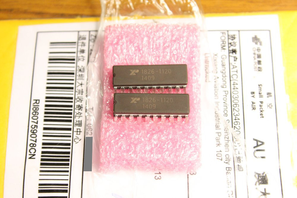
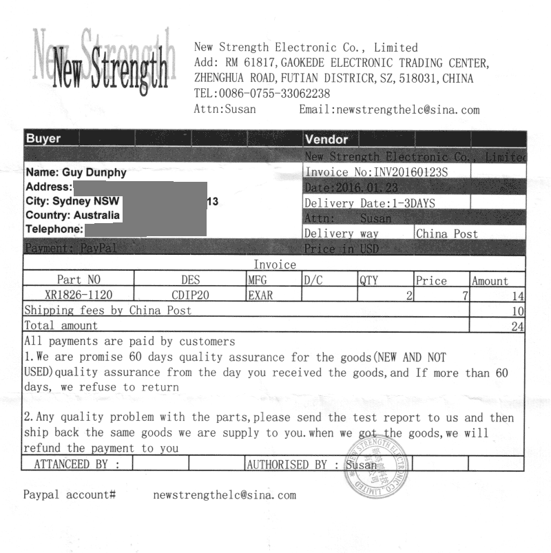
They are 20 pin ceramic DIP, have an Exar logo and the right part number, so that's promising. However they are awfully shiny and new for such old parts. Plus if that "1409" is a date code, it would mean 14th week of 2009, which seems improbable.
So what now? These are suspicious-looking enough that they must be tested now, rather than simply storing them as spares for my HP 54121T scopes. But I'm certainly not going to just plug one into the socketed power supply board and see what it does. Because it could damage other parts on the board.
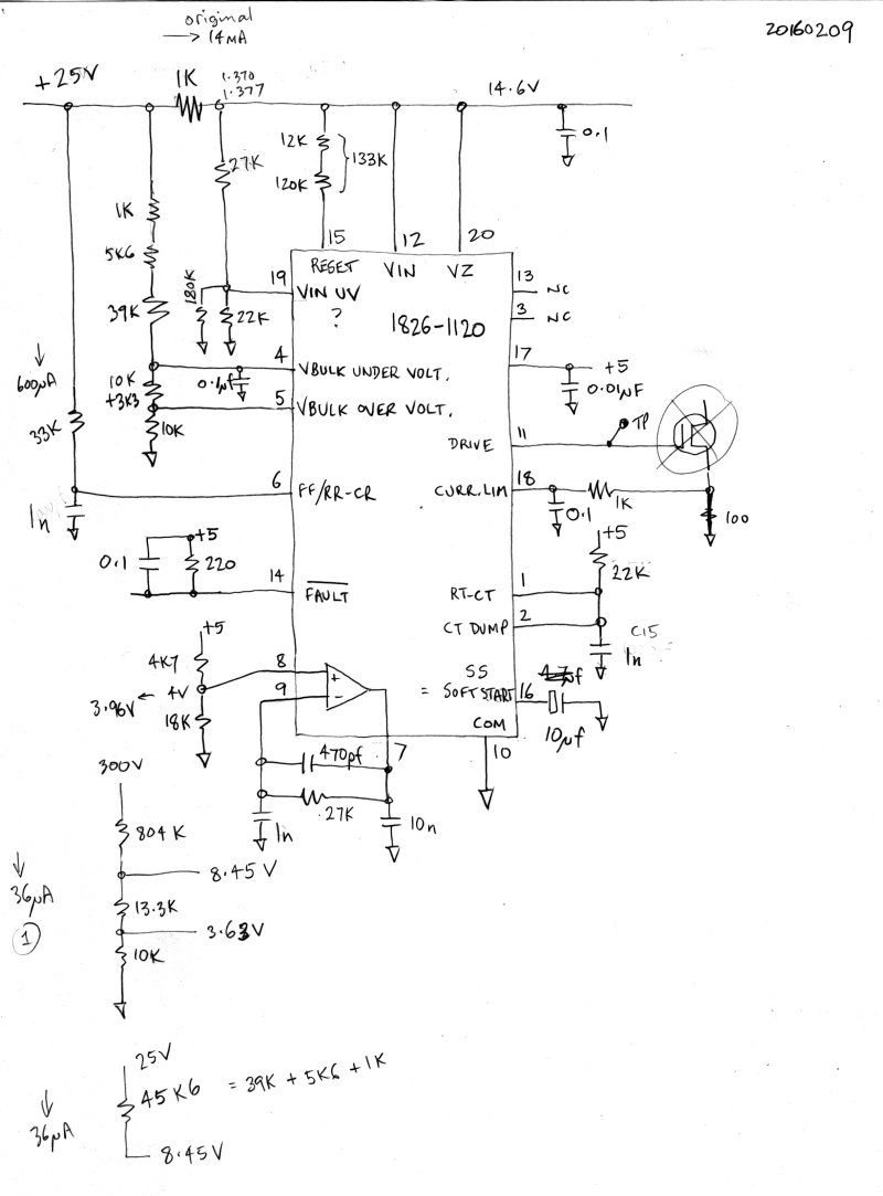 There's no chip data available, but I do have the board schematics.
The simplest way to tell if these chips are really 1826-1120 parts, would be to see if the VZ pin (which I presume stands for "Voltage Zener") does actually clamp a source current drive to around 14.6V. I wired a protoboard with pretty much only pins 10 (Gnd) and 20 connected, applied 14mA of current to pin 20.
Nope. Pin 20 only pulls up to a bit over 1V. Other pins are showing some portion of that too. But nothing even vaguely like the real chip should act. Hmm... by now I'm highly suspicious. But need something more solid.
So try again. Perhaps the chip is in some shutdown mode, due to VBULK UNDER VOLT being too low? So give it all the right levels. The circuit at left is a pretty close simulation of the actual Primary supply environment of the IC.