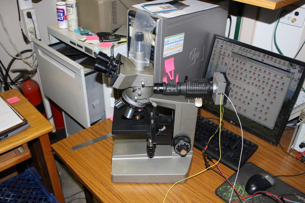
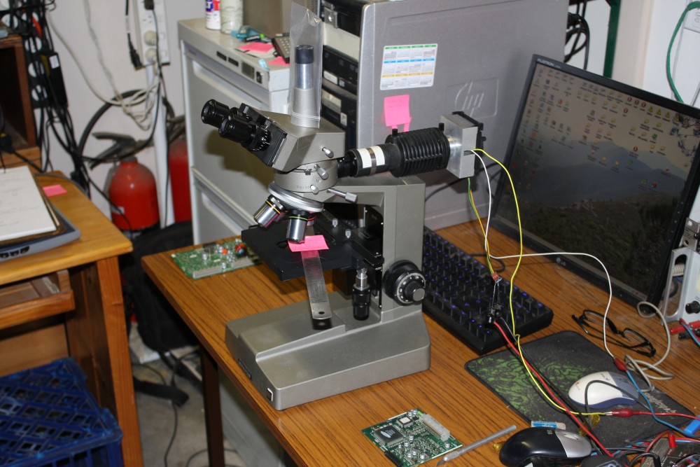
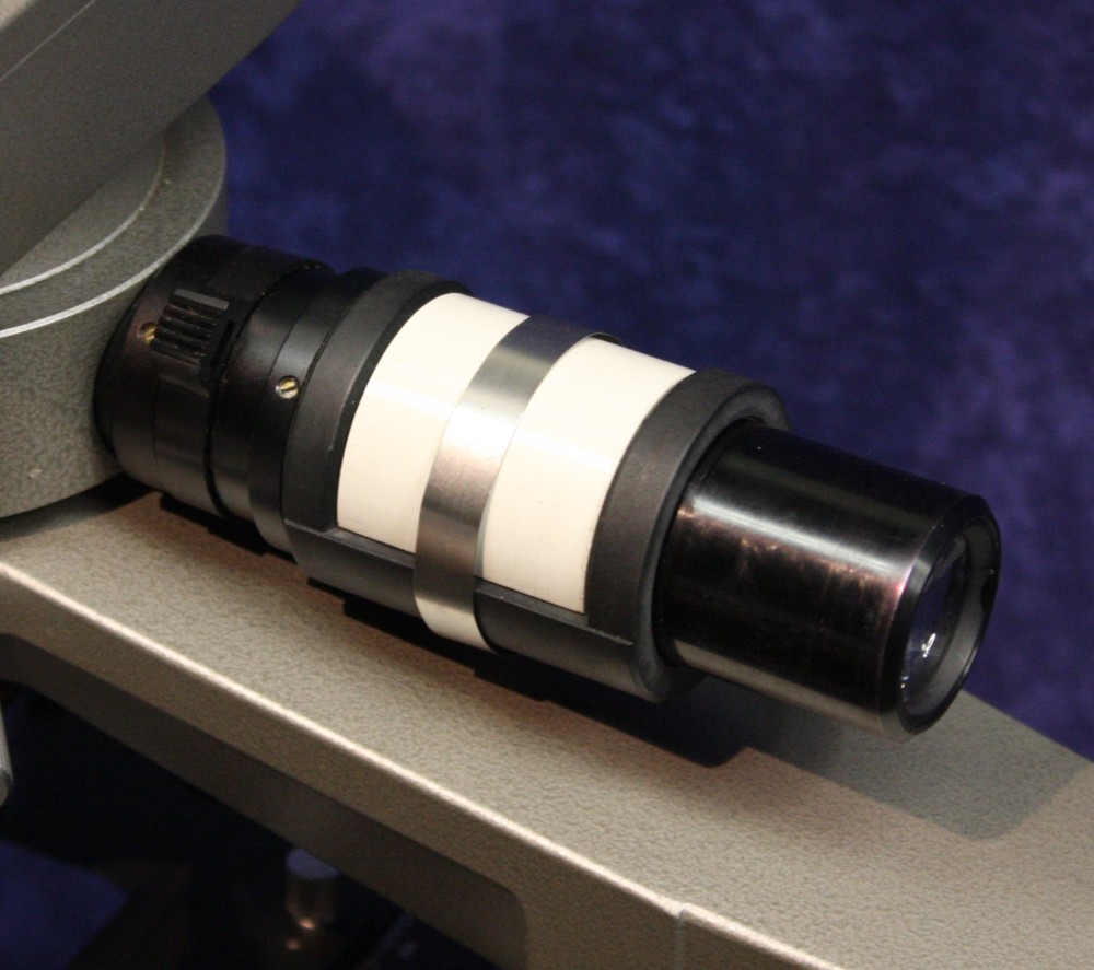
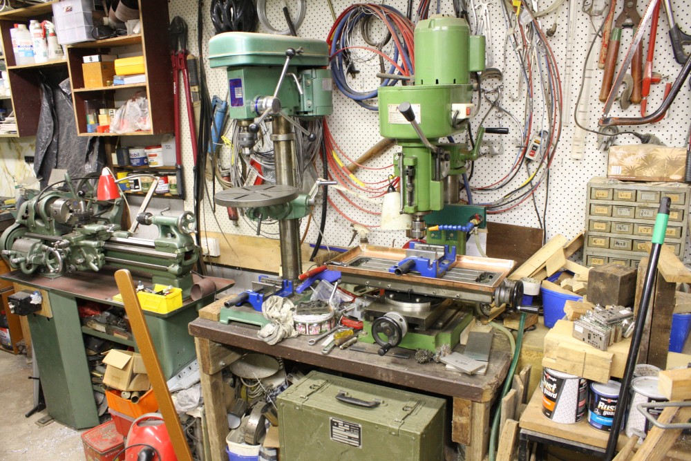
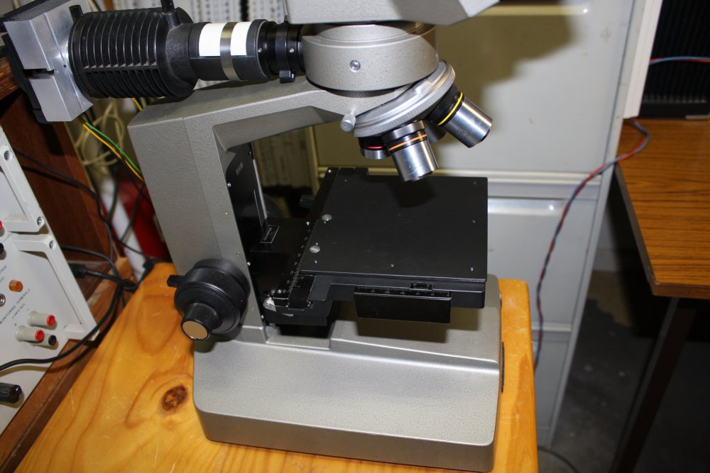
After adding new LED lights to my AM Forty binocular microscope, my next microscope project is to get this beautiful old Olympus BHM working.
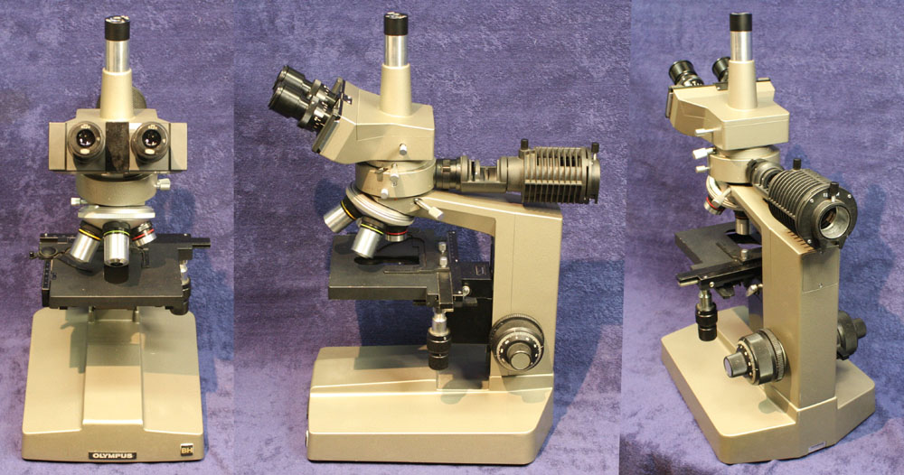
The "M" stands for Metalurgical, which means it's designed for looking at opaque things. That's why there is no illumination from under the stage. See The BHM Metallurgical Microscope.
Unfortunately with this one there's no illumination at all, since it was missing the special bulb that goes in that black lamphousing at the rear.
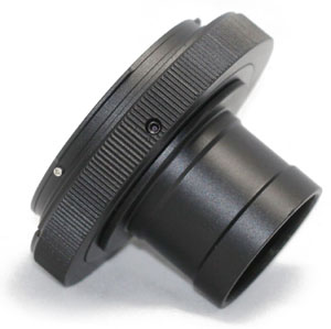
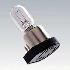 The Net says they are available for about $20 to $30 each, and they look like this.
But my enthusiasm for buying a special $20 filament bulb, of a presumably increasingly rare type (and a couple of spares) is low. Or zero.
I'd rather find a permanent solution, and all the better if it gives more light too.
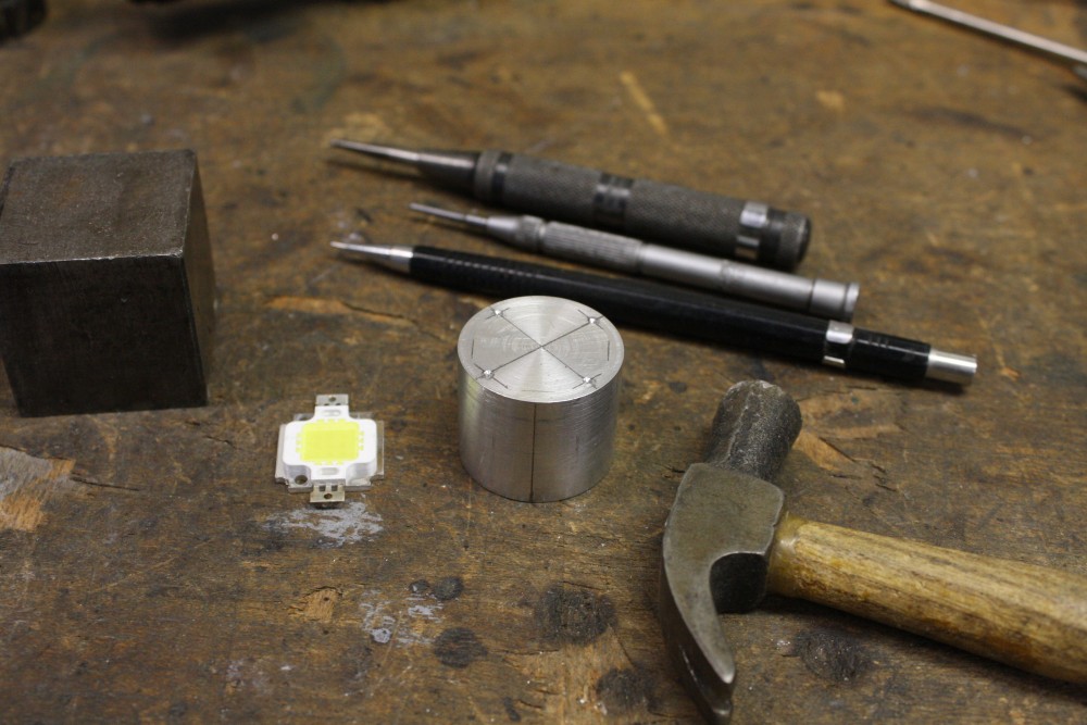
The bulbs are 15W; how about a 10W white LED?
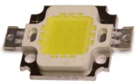
Au$8.40 for 10 of those, is a lot nicer than $20 for one bulb.
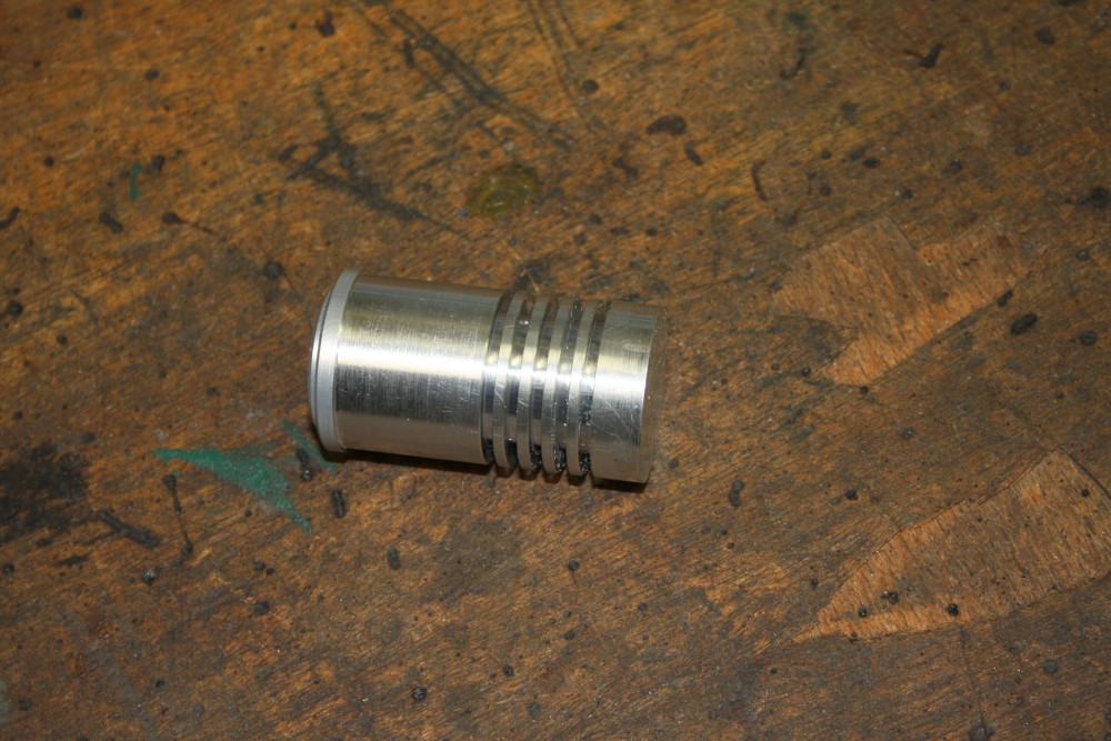
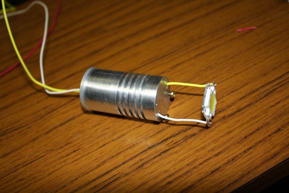
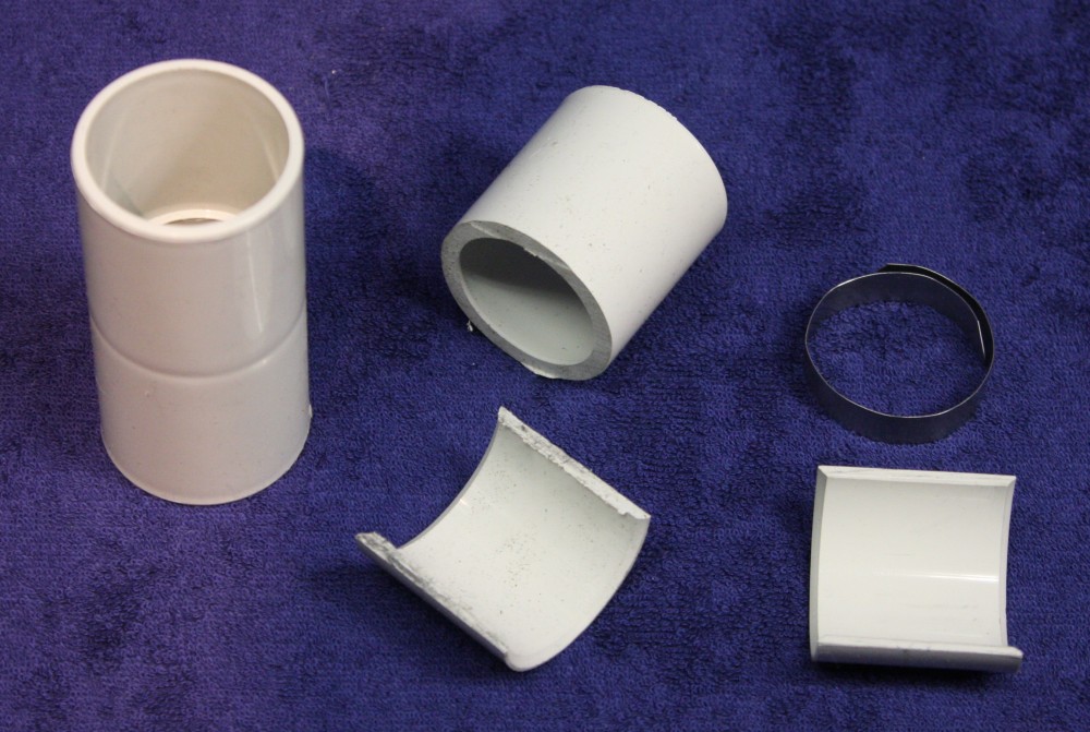
And so to the mounting. Luckily these 10W LEDs fit in the 30mm diameter opening of the lamp housing.
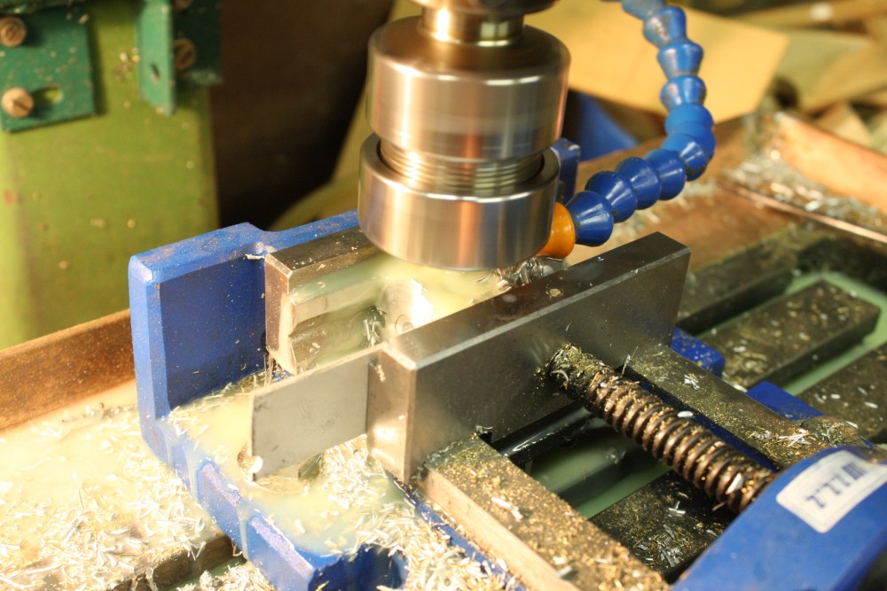
The first attempt wasn't very successful. The LED has to be held about where the filament of the lamp would be, and it needs a heatsink with enough surface area to dissipate the waste heat. I found a bit of scrap aluminium bar, and machined this:
 |
 |
 |
 |
 |
 |
 |
 |
 |
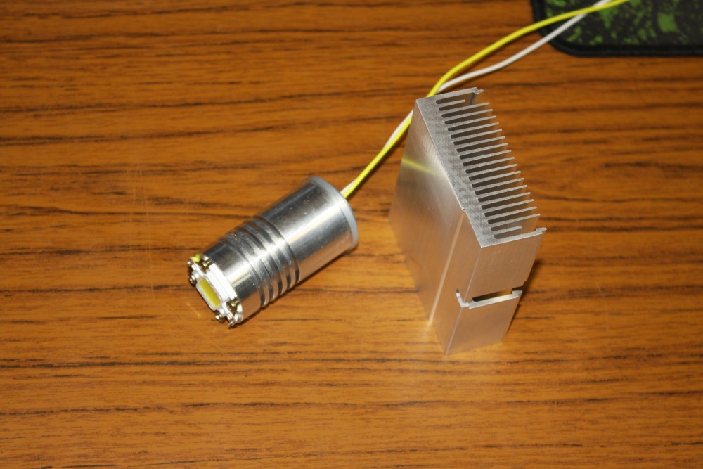
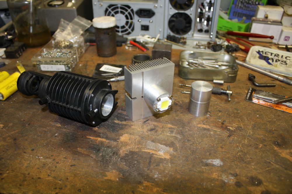
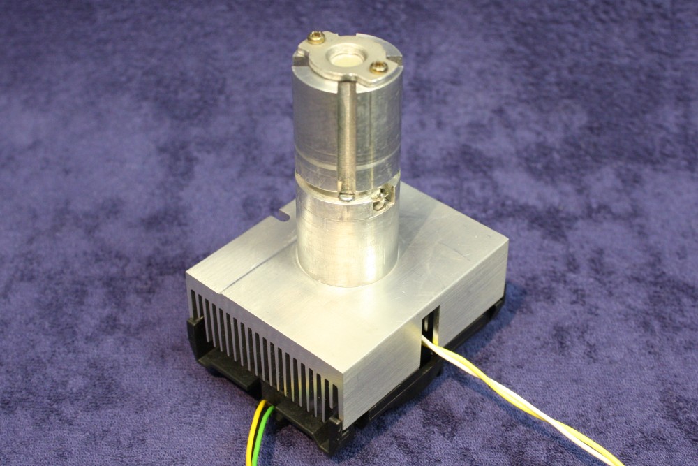
I'd optimistically hoped the fins I machined around the body would be enough for heat dissipation, but when I tried it they most definitely were not. So I added the square finned heatsink at the rear, which is off a PC CPU (no idea what variant, I just have a junk box full of these heatsinks) and comes with a clip-on fan. Without the fan it still gets quite warm, but with the fan it runs cold to the touch. So heat dissipation was a success, but...
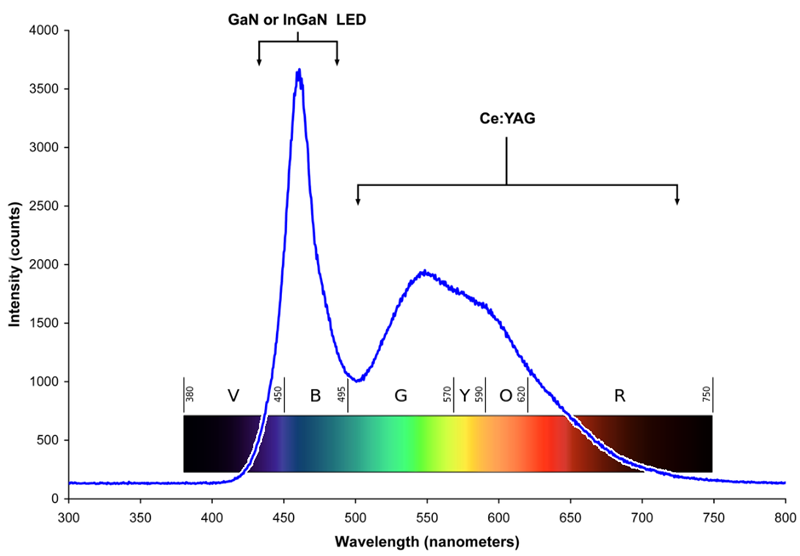
These 'white' LEDs are actually a 3 x 3 array of blue LEDs embedded in a yellowish phosphor carrier that absorbs some of the blue photons and re-emits as yellow. The result looks white to the eye. I knew they are deficient in green wavelengths, and decided I could live with that, at least in this microscope.
What I hadn't counted on, was that these LEDs don't produce a uniform colour light field. When you shine them on a nearby white surface the result looks even, but if you focus them through an optical lens system you end up with a projection of the 3 x 3 array of blue LEDs. Looking at things under the microscope with this light source the brightness is great, but there are obvious blue/yellow contrasting effects. The illumination system is lenses all the way from the bulb to the sample surface, so some of that 3 x 3 array uneveness ends up at the target.
Time for a rethink.
What I really need is to concentrate the light from the LED, to a small aperture — with the aperture placed about where the bulb filament would be. Also the concentrator should mix up the LED light paths enough to lose any trace of the 3 x 3 blue LED array.
And so, Take Two.
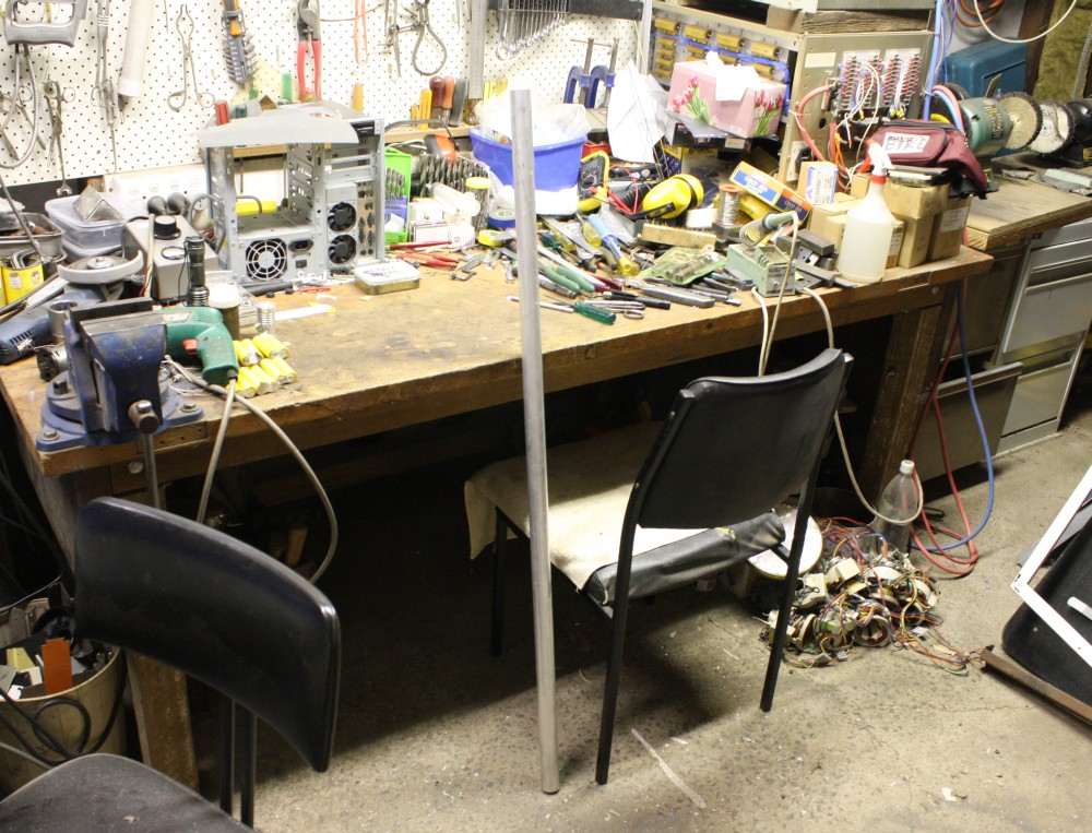 This time I had no more suitable bits of scrap aluminium bar, so bought a 1.5 meter offcut of 32mm round bar.
Amusingly it cost about the same as one of those silly-looking bulbs would have. But at least this bar isn't ever going to go tink and stop working. It does make a lovely bell-like tone when held at a vibrational null-point and struck though.
This time the construction I had in mind was almost complicated enough to do some kind of plan on paper. But nah. Just do it.
In general the idea was to have the LED mounted as before for heatsinking, but further back. Then have a lightly tapered conical cavity above the LED, with internal reflections bringing the light to a small aperture. The aperture would be about the same diameter as the size of the filament of the original bulb, and adjustable to be in the same position along the optical axis. I'd also provide an option to include a diffuser on the aperture.
The conical cavity would have aluminium walls, and I wouldn't be able to polish them. But I had an idea for a way to get their reflectivity up to near-mirror like, to minimise losses.
Anyway, first I cut off about 7cm of that round bar, and turned it down in the lathe to be a nice fit to the 30mm inside of the lamp housing. With the slight problem that without mucking around with center holes and a drive key in one end face of the piece, some of the end has to be held in the lathe chuck. Which means the entire length can't be turned to the desire diameter in one pass. But taking it out of the 3-jaw chuck and turning it around to do the other end inevitably results in a very slight missmatch where the two cuts meet. More of a visible blemish than anything serious. Another way would have involved switching to a 4 jaw chuck, and using a dial gauge to zero centering error. Also couldn't bothered with that.
So, feeling a bit cheesed at the tradeoff between perfection and laziness, I forgot to take photos of that initial stage.
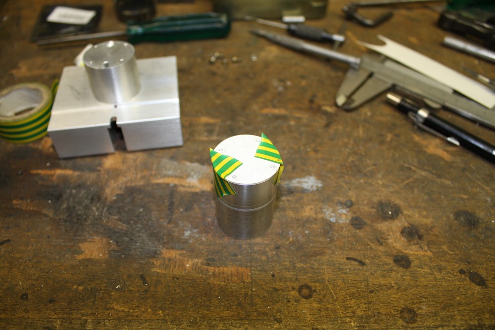
 |
 |
 |
 |
 |
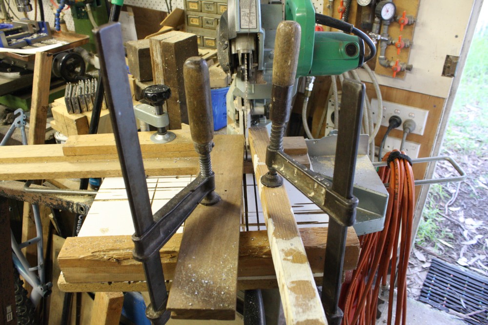
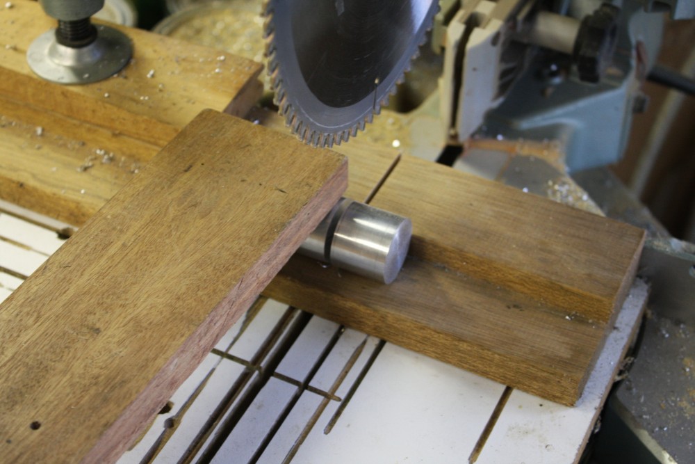
The first two photos are of cutting the resulting correct-diameter piece into two parts. I don't have a parting tool able to do that depth of cut, so used the drop saw. Not something you'd want to hold with the fingers close to the blade, and besides, it would move. Hence improvised clamps. Notice I've oversized both pieces, so the ends can be turned flat properly in the lathe.
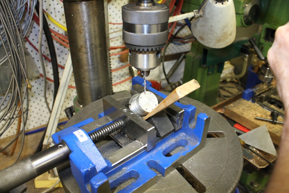
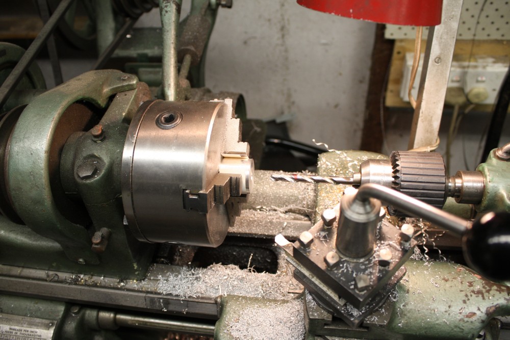
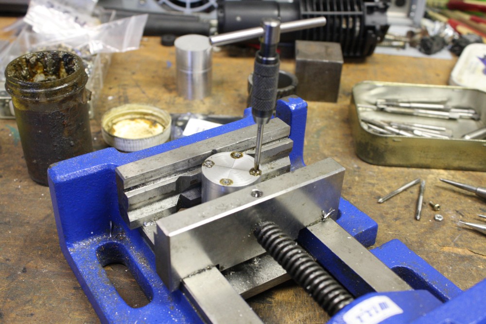
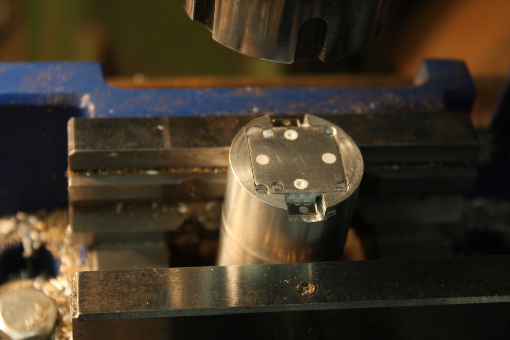
#3 is the LED heatsink piece having a hole drilled part way through, for the power wires.
#4 is marking and centerpunching the LED mounting holes. More carefully this time than I did with the first failed attempt, as one of the screws in that one was a wee bit too far towards the center, and needed a little bit filed off the LED frame. Fraction of a mm, but annoying. This time was all good.
#5 Tapping those holes, for 2.5mm screws.
 |
 |
 |
 |
 |
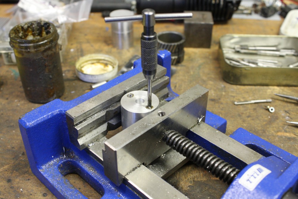
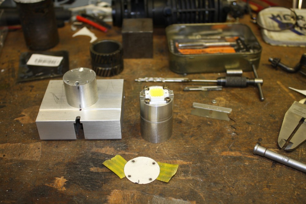
#1 Tapping holes at the other end for the finned heatsink.
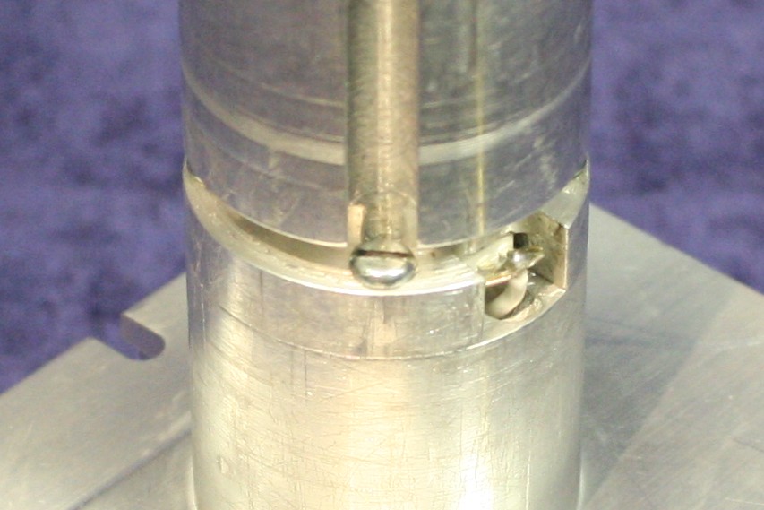
#2 Assembled. The other piece is there too, showing that difference in the two surface passes. I don't care! (OK, yes I do.)
#3 Now a tricky bit. The next piece has to have four M2.5 clearance holes, matching the screw holes in the first part, and allowing the two cylinders to be joined with no surface offset. Since the joint has to pass into the lamp housing, and it's a close sliding fit. Tell me if you know a better way, but this works for me. Cut a bit of stiff paper to match the OD of the cylinder. Tape it onto the end with the existing holes. Rub it firmly with a fingernail, and the edges of the holes will make impressions on the paper. Now tape it other side up onto the blank end. Centerpunch through the paper, visually to the centers of the marks on the paper.
Ideally, I should have done this before tapping the holes in the first piece, since the thread end isn't quite true to the hole center. But I forgot.
#4 Sanity check. Screws just dropped into the clearance holes, do fit the LED frame nicely. It will be a little while before I can try screws through the two pieces.
#5 Starting to mill a cavity for the LED body. It's going to be clamped between the two pieces, with the upper one bearing on the edges of the LED metal base plate to ensure good heatsinking. Plus of course there will be heat conductive grease.
 |
 |
 |
 |
 |
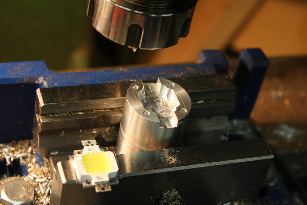
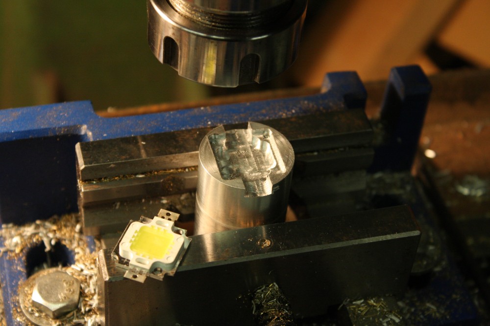
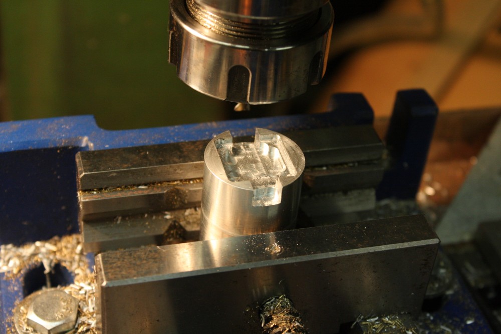
#1 The second layer of cutout milled. I was doing these cuts by eye, to lines scored on the metal surface. Awkward since the small milling bit is also short, so the mill chuck was close to the piece. Even with the old planet lamp I have on the mill table it wasn't enough light, so I resorted to holding a very bright UltraFire torch close to it while squinting into the gap and working the mill drive with the other hand. And being careful not to get my long beard caught on the spinning bits.
#2 Showing the fit of the LED.
#3 Cutting deeper slots for clearance of the LED power tabs.
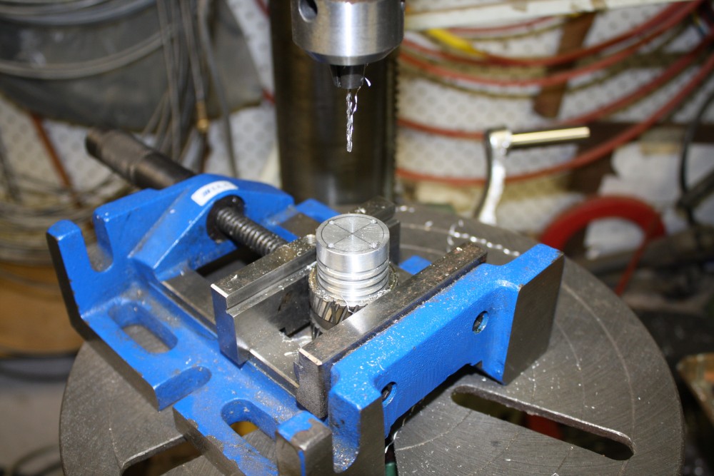
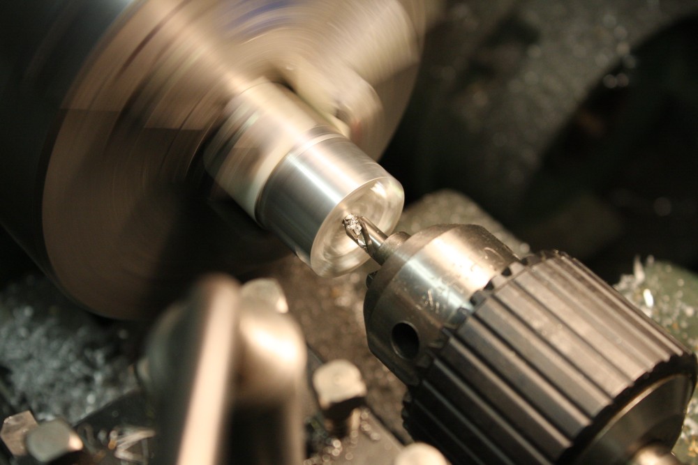
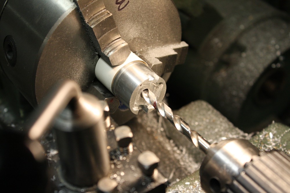
#4 Center drilling, to start work on cutting the internal taper.
#5 Plain drilling right through. This hole has to be smaller than the size I want for the far end aperture. I'd like that as small as possible, but it has to be large enough to fit my smallest inside boring tool.
 |
 |
 |
 |
 |
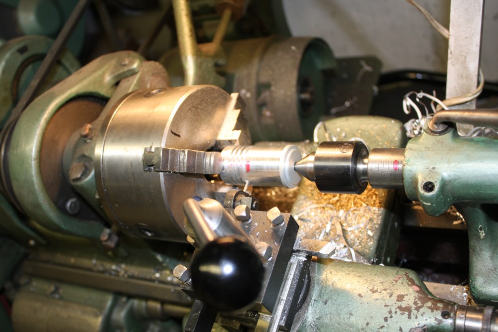
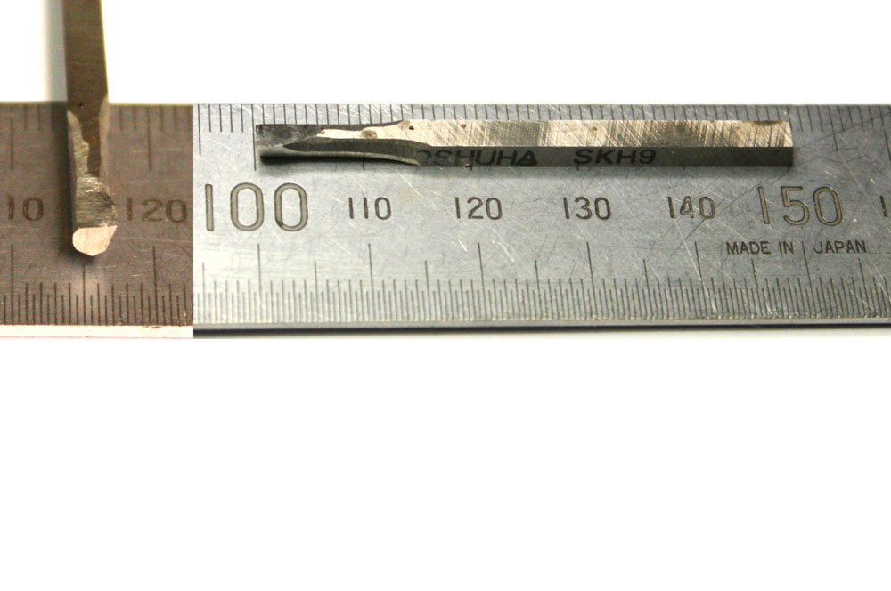
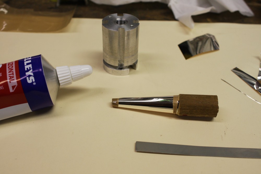
#1 This little one. A 3mm square piece of silver steel. Question was, would it work at nearly full extension into the hole?
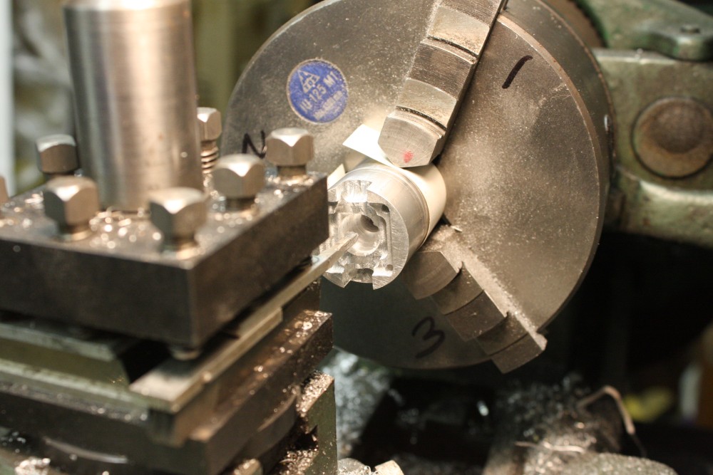
#2 Starting the taper bore. I began with 4 degrees taper, and that ended up being a good enough guess. Though if I did this again I think I'd aim for a smaller hole; maybe 3mm at the aperture, and 12mm dia opening above the LED.
The further I had to extend the mini-bore into the hole, the lighter the cuts I took. By the end I was being very very light. Couldn't really believe it was working. As opposed to snapping off, or flexing enough to chatter. Squirting kerosene into the hole as a cutting fluid, and blowing out swarf with compressed air helped.
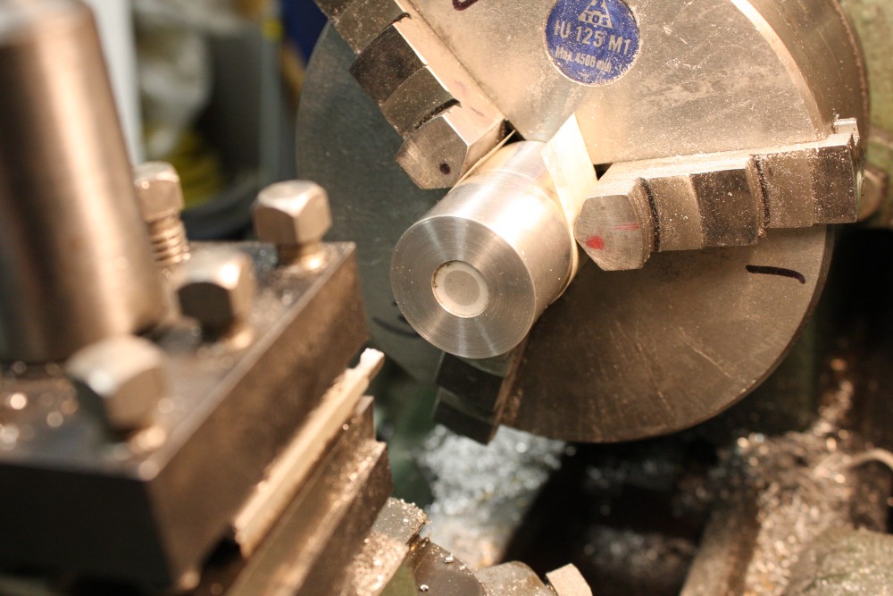
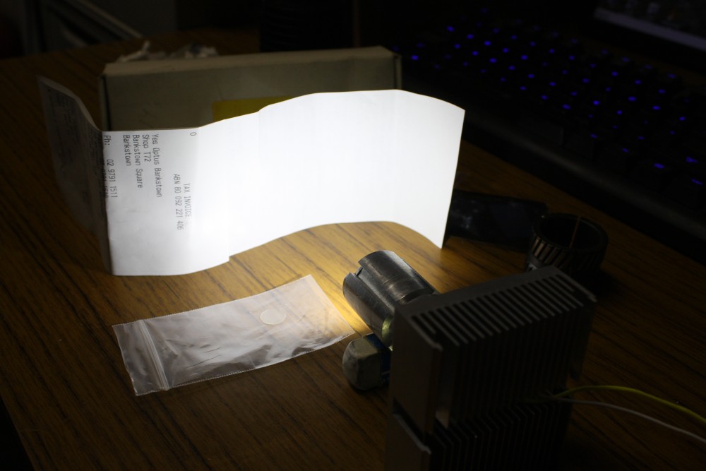
#3 With the tapered hole finished, I cut a recess at the end to take pieces of plastic film. I have a variety of different kinds with different optical properties, mostly salvaged from LCD monitor screens. I sized this recess to press-fit bits cut out with a hole punch.
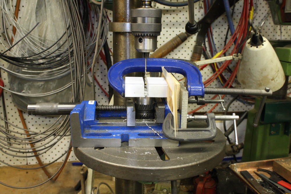
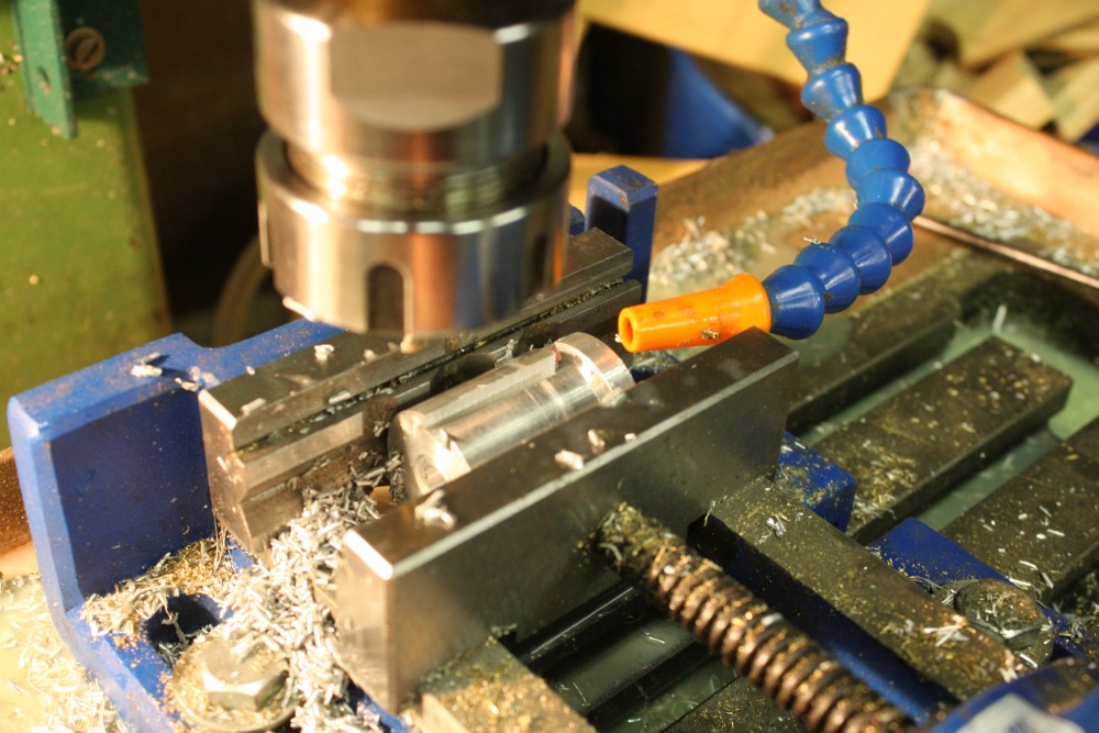
#4 Here I've already cut a recess as seating for the screw heads, and am now milling slots so the screws can be slid into the holes and accessed with a screw driver. Actually that slot was bad — I didn't lock the mill vertical depth hard enough, and it drifted up during the cut. No harm done, just needed to be recut.
Wait, is that...? Sigh. Yes, there's surface rust starting on the vice. Seems I've been slack, and forgot to oil-wipe things after the last time I used it. Then a few rainy weeks... Note to self: clean up this time. And do some damned maintenance.
#5 Also on the remaining slots I added cutting fluid, as the bit was binding in the aluminium. I hate this stuff, and avoid it when possible. It's impossible not to get it on your hands, and a pain to clean the mill bed afterwards.
 |
 |
 |
 |
 |
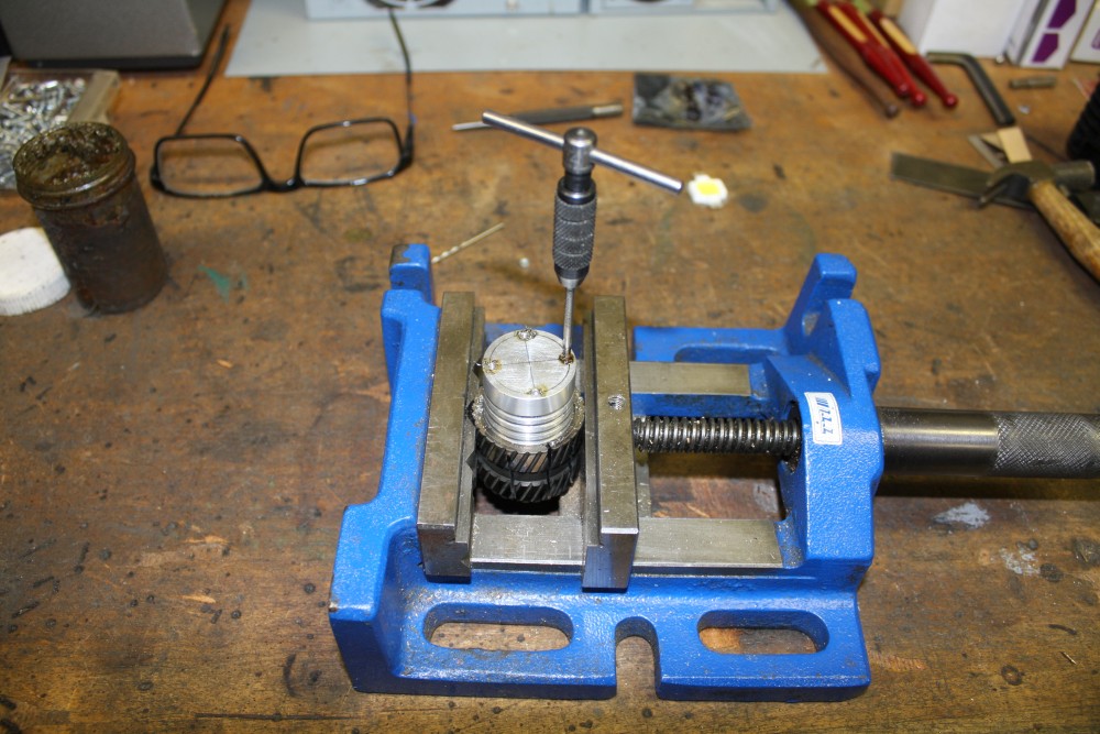
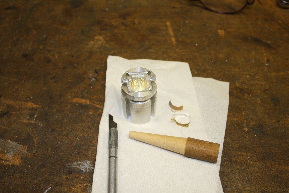
#1 Tapping holes for the diffuser disk holder. Which is sitting on the machine vice next to the piece. It's hand cut and filed from a bit of scrap aluminium sheet, and a lip knocked into the centre hole with a big punch and a tube as base.
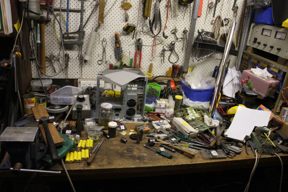
#2 Just the workbench at this stage. Tidy up comes later. Maybe.
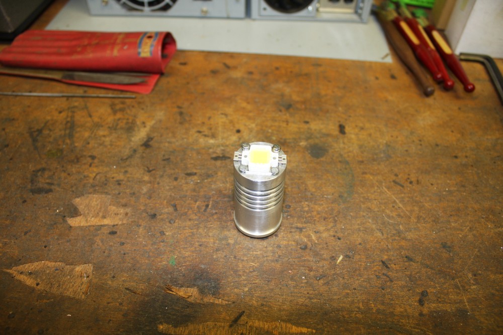
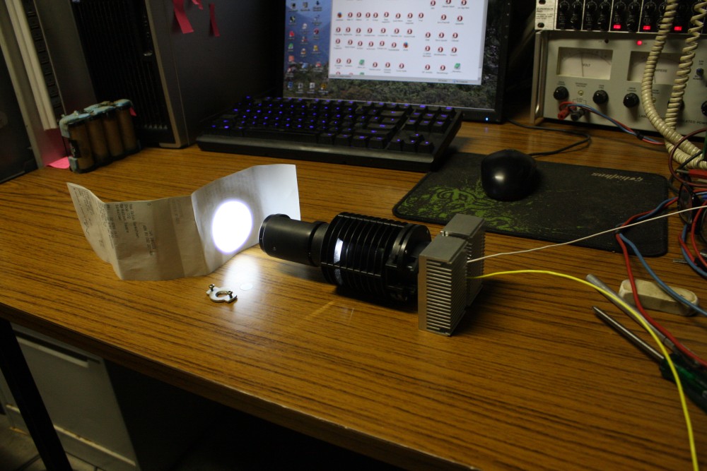
#3 Assembled. So far the inner light cone is just bare machined aluminium, which although light coloured is absorbing a lot of the light with each bounce. Not to mention random angles of reflection on surface roughness.
All the same, the end aperture is damned bright. Too painful to look at directly.
#4 A quick illumination evenness check. It's good - no noticable trace of yellow-blue blotches. Not that I'd expect any, with the amount of reflection randomness from that machined metal surface.
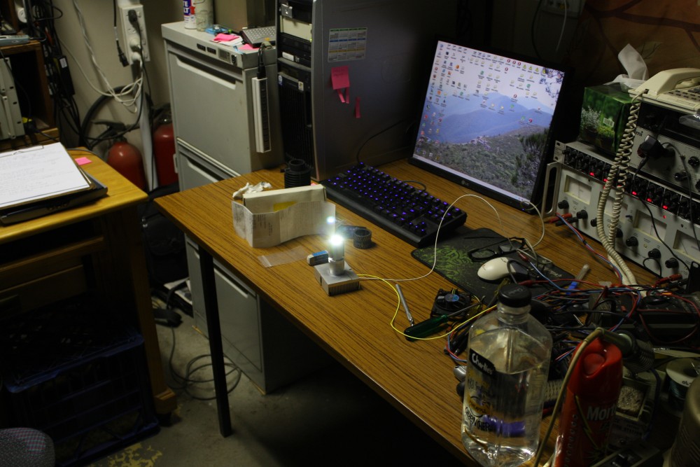
#5 A brightness check in the microscope. Cool, it's already brighter than the first attempt. Also now I can slide the whole thing axially, to adjust matching to the internal lense system. There's a definite brightness peak at the position it's in for this photo. I also ran it for a while to let it get hot, then with the fan running. Back to room-temp cold within a minute.
 |
 |
 |
 |
 |
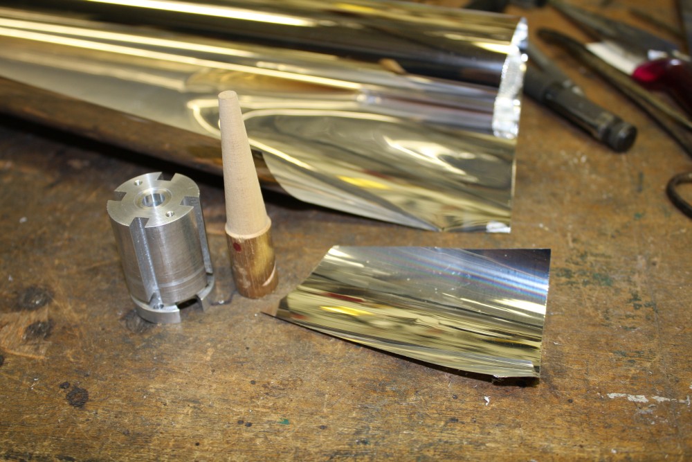
#1 Next, how do you make the inside surface of a smallish tapered hole into a mirror finish? A: by glueing a mirror finish film to it. I recently disassembled some old rear-projection TV sets. A couple of them had big mirrors constructed of a thin metalized film stretched tightly over a frame. Now I just needed a way to hold the film hard against the walls of the taper while the glue sets. And so, a bit of wooden dowel gets machined with the same 4 degree taper as the hole. Sorry about the poor focus here.
#2 A piece of the film roughly cut. Then wrapped it around the dowel, and adjusted the cut to get it sitting right, with a small overlap up one side.
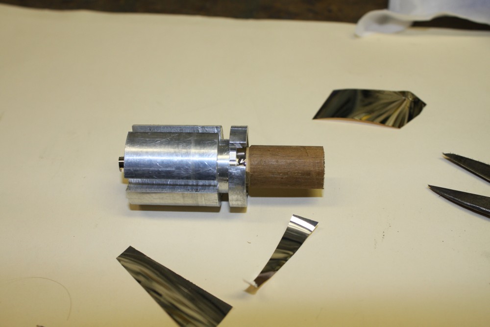
#3 The film held in place with the dowel, and some excess at the ends.
#4 Getting ready to glue it. Cracked open a new tube of glue so there wouldn't be any lumpy bits. Smoothed the end of an old stainless steel cable tie offcut to use as a light springy spatula, since I didn't want to put any scores in the film. After lightly covering the film surface with glue it was just jammed hard into the tapered hole and left there for a few hours. Glue squeezed out the ends, but that's fine.
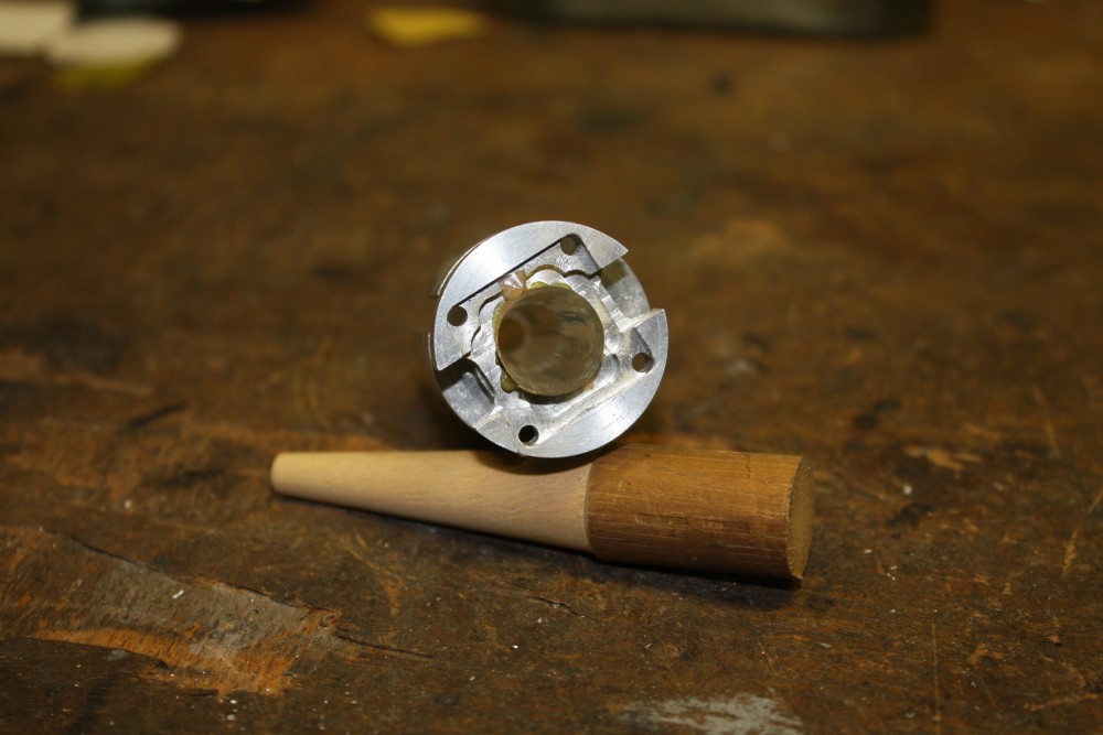
#5 Later. The dowel came out easily, meaning no glue got between it and the film. The result is looking good, though it doesn't show in the photo. Very shiny!
 |
 |
 |
 |
 |
#1 With the excess bits pared off, it looks great. Just putting it on a white surface makes the inside seem to light up, so I guess the reflectivity is as high as I'd hoped. The surface geometry variations you can see are also good, since that will help break up the 3 x 3 LED image.
#2 Ha ha, but not enough. You can't see it in this photo since the white light area is saturating the camera. But the eye can see a blue/yellow pattern. Kind of like a kaleidoscope image, but not acceptable.
#3 So I added one of those little disks of diffuser film at the aperture. Now it's good.
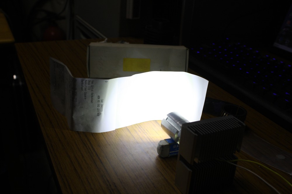
#4 Oh boy is this thing is bright. I've no idea by what actual percentage increase since before I added the mirror film, but it's now stunningly intense, from such a small opening. You really can't look at it at all, and the camera is having halo and internal ghost reflections in its lenses, like you get from the Sun.
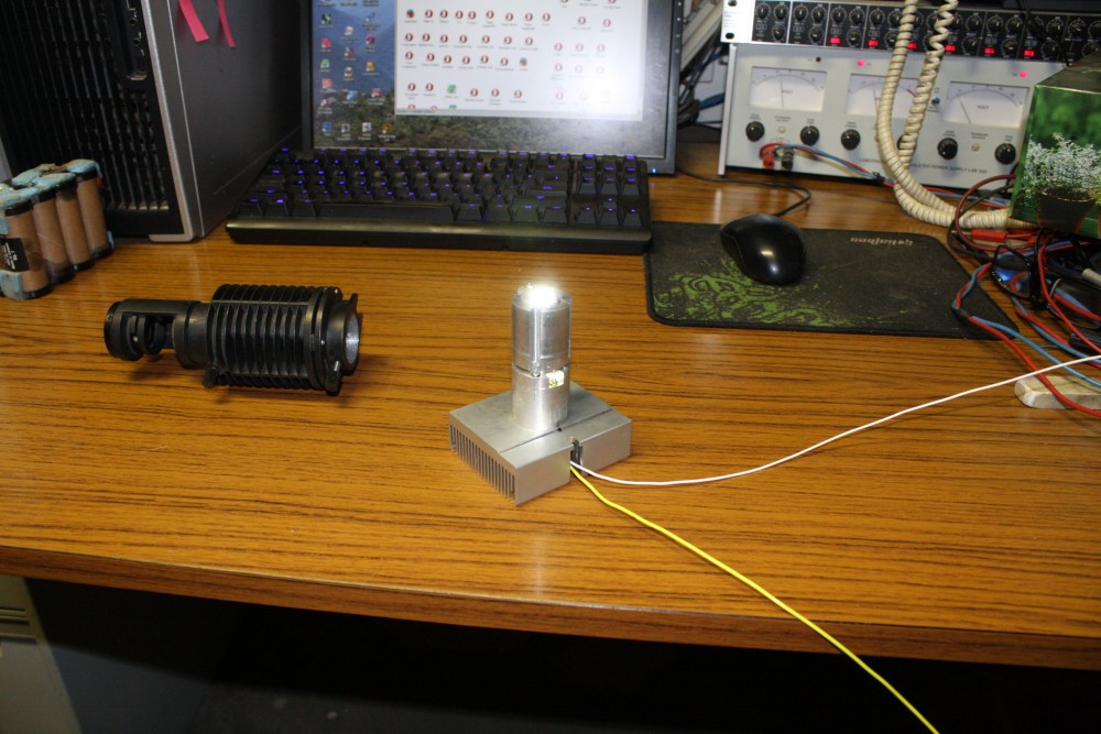
#5 Trying it. Yep, now it's really splendidly bright. I'm happy.
 | ||||
 |
 |
 |
 |
 |
 |
#1 & 2 Finished. Or at least till I figure out how I want to neaten up the cables. The fan and LED could almost be run from the same supply, since the LED takes a constant current supply but the voltage ends up being nearly 12V. While the fan is constant voltage 12V. It wouldn't be a bad idea to add a fan rotation interlock. Since the fan already has the tacho-sense output common on CPU cooler fans. No fan rotation, no power to the LED. But this means they have to have separate positive supply wires. Or the interlock circuit could be on the heatsink, and include a current regulator for the LED. Then only a plain 2-wire 12V DC supply would be needed. I like that way better.
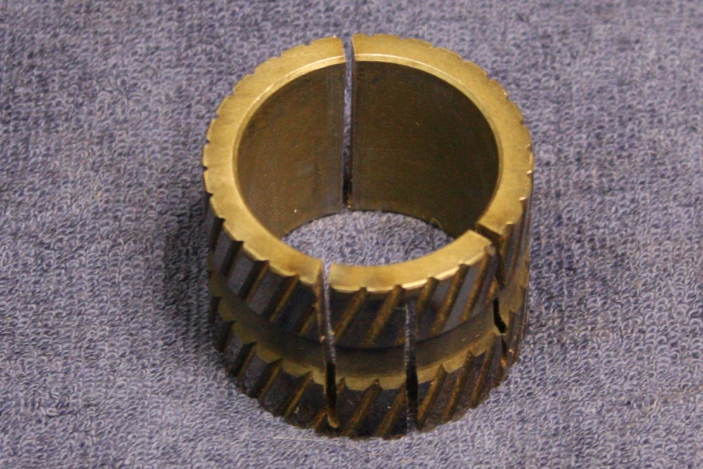
#3 One of those nice serendipitous things. At several stages in machining the LED lamp body I needed some kind of collet, rather than risk making chuck or vice marks in the piece surface. This bit of metal is from a Mazda gearbox, that I'd had in my bin of small metal blocks useful for spacers. Made of very hard steel, it just happened to be a perfect tight fit on the 30mm dia aluminium piece, after I cut a few slots in it with an abrasive cutting disk. You've seen it in many of the photos.
#4 Yes, I remembered that rust. This pic is after a swarf cleanup and general oiling of everything. As for a total tidy up, no no that's expecting too much.
#5 Wiki says: a graph showing the deficit of green in the light spectrum of these white LEDs. This is why I left so much metal on the extension body of the LED holder. It occurs to me that it might be possible to add a separate high power green LED on the side, with a light path up towards the diffuser at the aperture. With adjustable power to the green LED it should be possible to get a much flatter spectral power distibution. The green LED wouldn't have to be 10W; maybe 1W or 2W would be enough? Or a white LED combined with red and green LEDs, if there was room.
The reason I'm interested in pursuing this, is that I have yet another microscope to do. It's the best one yet; a Zeiss Universal. It's supposed to have two lamp housings, and ideally these should be high pressure mercury arc lamps to give a broad spectrum extending into the UV for fluorescence studies. Gradually I'm finding suitable bits on ebay to complete this microscope. But the special mercury bulbs (50W, 70W or 100W) have quite limited operating life, and cost a lot. Even better they may explode in use, damaging nearby optics and reflectors. I'd rather have a cheap, safe and long life illumination for normal use, and switch to the arc lamp housing only when absolutely necessary.
With the Zeiss Universal, the lamp housings can be quite large. So it's entirely possible to use, say, multiple 50W or 100W LEDs, combining the light from them into one with techniques like in this little experiment with the glued-on reflective film. It's even possible to buy UV LEDs covering 415 to 420nm, in powers up to 100W.
 But first, interfacing my Canon EOS camera to this Olympus. Actually the reason this illuminator got done now, was that an entirely different project is stalled until I can take photos of some very small parts for it. And that project is holding up another, that needs the finished product. Sigh... so typical.
Anyway, this adapter is in the post. Hopefully it will work. Though I'm wondering how I'm supposed to get focussing right with the camera.
I can't get over how wonderfully this microscope works, compared to all the simpler ones I have ever used. It's just stunning. In this BHM the light goes down a separate channel in the objective lenses, and shines on the sample from all sides, close to the objective final lens. The result is really excellent bright and even illumination.
With 10x eyepieces, and Neo5, 10, 20 and 40x objectives, that gives a magnification range of 100x to 400x. All spectacularly clear. I love it! Looking forward to digital copies of scenes taken with it.
Update 20150528
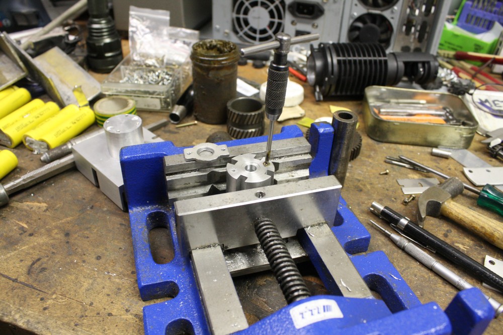
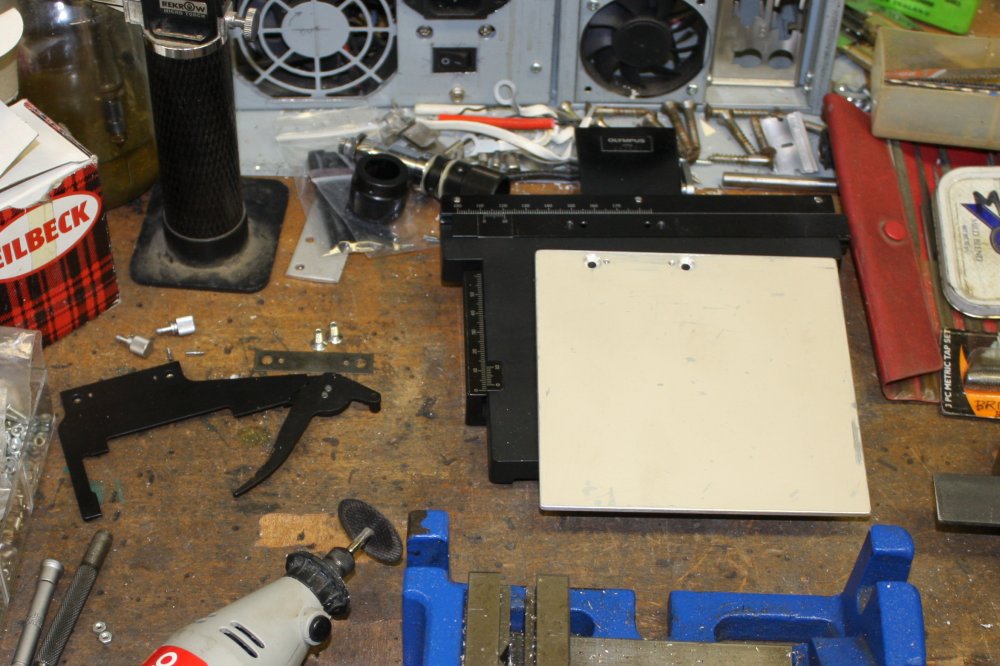
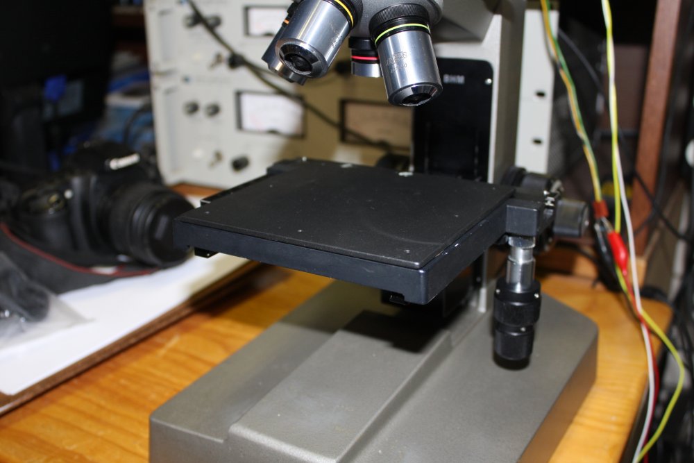
I added a flat plate to the X-Y positioner, so things don't fall through the hole in the fixed position stage.There are M2.5 threaded holes around the edges so I can add clamp-downs if needed.
An amusing detail for those who know their electronic synthesiser history: the metal plate is cut from a Fairlight CMI front panel. I used to work for Fairlight Instruments long ago, and once they were throwing out a pile of obsoleted metalwork. I grabbed it all, and so have about 50 of those front panels. Series One, I believe.
 |
 |
 |
 |
The X-Y movement knobs were stiff (old grease) so I disassembled it all, cleaned the hardened old grease off, regreased and reassembled. I don't have any of the correct high viscosity grease, so used lithium grease. Now the X-Y movement is easy. Probably too easy, but since it's not the vertical axis drift doesn't seem to be a problem.
I used Permatex White Lithium Grease; AU$7.50 for a 1.5 fl Oz (44.3g) tube. From ebay seller samuels_bits.
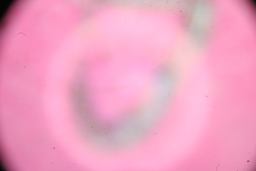
The last pic is from the first attempt to use a Canon EOS camera with the new camera tube. Ha ha, miserable failure. It's pink because I had a pink post-it note on the stage. The gray blur is a loop of lead pencil writing. This first attempt was with my old EOS 20D, that has no ability to give real time video out, so there's no way to adjust the focus live.
I thought that would be a problem, unless by a miracle the focus just happened to be perfect. Still, it's promising since the focus is obviously not too far off. As opposed to being optically completely mismatched. The bright ring I think is probably due to the cheap-arse camera adapter tube having a black but mirror-finish anodized inner surface, and no anular baffle in the tube. So side overspill light is reflecting off the tube walls and ending up on the sensor. Solution being obvious - make the tube walls matt black, and add a baffle. The tube end is actually threaded on the inside for such a baffle (or lens?) but it seems the Asian cost-cutting principle has been applied. Leave it out and see if anyone complains.
Anyway, next attempt will be with my Canon EOS 40D, which does have live video out. Thus allowing getting the camera and binocular eyepieces matched, while watching the camera focus on a large screen. Except first I'll have to finally set up the PC at the microscope bench, to install the Canon camera interface software. No way I'm installing it on my main working PC.
Canon EOS Camera Sensor Cleaning
Another result of that attempt, was realizing how very dirty the sensor of my EOS 20D had become, as you can see. There is no automatic sensor cleaning in this model. I went through the cleaning proceedure, removing lens and opening the shutter. First tried blowing dust off the sensor. Not enough, there is still dust visible in pics. So then I brushed the surface with an extremely soft brush.Somewhere in that process, a splodge of greasy gunk got on the surface of the sensor. Visible as a smear when looking at the sensor with the shutter open.
Ah crap. I'd been led to believe that 'the sensor' in these cameras is the directly exposed silicon sensor, and therefore extremely delicate. The kind of thing that could be ruined by touch.
At that point I googled for sensor cleaning. More of the same — general hysterics about how delicate the sensors are. Special swabs, special solvents, preferably done by profesional camera service centers, etc. Great.
I decided to have a look under a microscope. Is it really the bare silicon sensor?. Having taken lids off large chips before and actually probing connection pads when I was reverse engineering something, I find it hard to believe that 'exposed sensors' could possibly be a viable idea. Those things are soooo delicate.
Even with the lens removed and shutter open, the sensor is down the bottom of a fairly deep pit in the camera body, and it's hard to get a good, well illuminated view of it with my AM Forty binocular microscope. But with holding an Ultrafire torch for extra light down into the camera body, it was possible.
It took a little while, and running the focus plane back and forth to be sure of what I was seeing.
There are three different stacked surfaces visible:
- A front glass surface with a black surround framing, apparently adhered to the glass. This surface has gunk on it, ie dust and that greasy smear.
- A rear glass surface, that is bonded to the sensor carrier around the edges. You can see the glue. This surface is clean.
- The actual sensor silicon, with the gold bonding wires visible around edges. Also perfectly clean.
So actually these camera sensors are NOT directly exposed. They have a cover sheet of optical glass, much the same as old EPROM chip packages except the glass is optical quality. It might be quite thin, and you wouldn't want to press too hard in case of breaking it. But it isn't particularly fragile in the sense of having super soft delicate surface features, color filter blobs and tiny bonding wires. It's a flat glass surface.
Reassured by this discovery I ended up just scrubbing it quite firmly with ordinary cotton buds soaked in lens cleaner (and plain old Windex), then drying it off by more scrubbing with a cotton bud wrapped in lense cleaner tissues. Finally giving it some squeeze bulb air blows with the camera held face down, to remove any random dust fallen on the surface in the drying process.
Then took photos of a blank evenly illuminated white surface (out of focus) plus photoshopped the image levels to highlight even a few LSBs of noise. Now the image is perfect - no trace of specks or smears.
So funny to discover all the whining folklore about these camera sensors being super-delicate is utter bullshit.