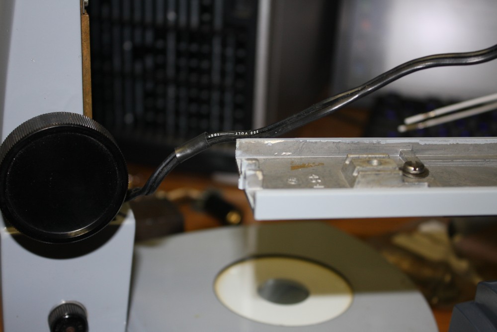
With the tiny components in electronics these days, it's essential to have some kind of inspection microscope, and preferably binocular, with a good depth of field. Especially when your eyes are no longer as good as they were.
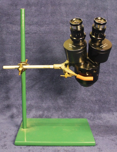
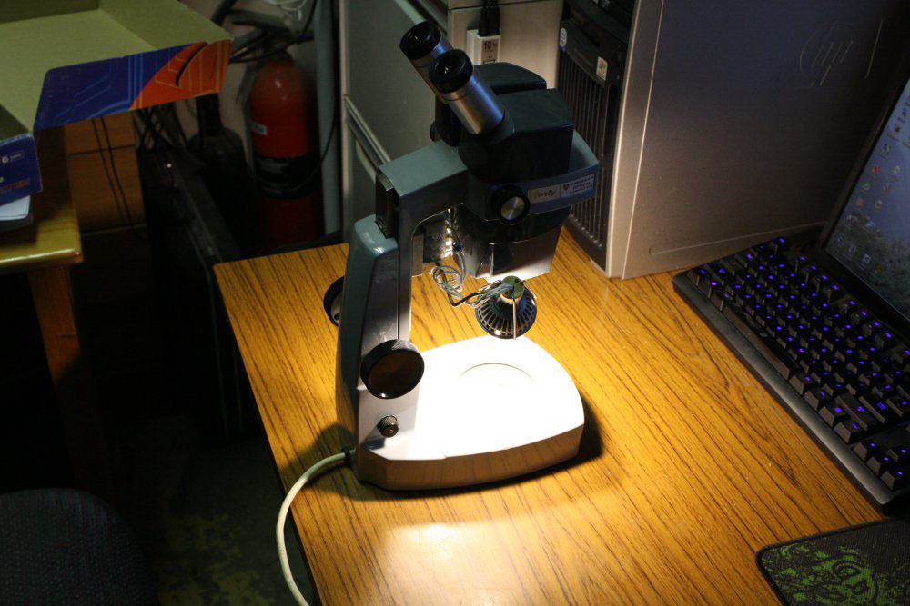
This is not the one I'm LED-lighting. It's what I've been using for binocular inspection for a few years now. Obviously it has some drawbacks. Cost was not one of them. The optical magnifier came as part of a junked optometrist's laser eye treatment rig I was given, sadly minus the laser. In itself it's a nice bit of optics, but it needed a stand of some kind.
So what it got was this — a base and rod stand I'd made from scraps of steel, and a couple of bits of standard lab glass clamp pieces.
It works, so long as you don't mind not having a height adjustment or any built-in lighting, and can ignore the sneers and eye-rolling from anyone who sees you using it.
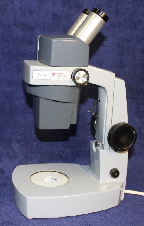
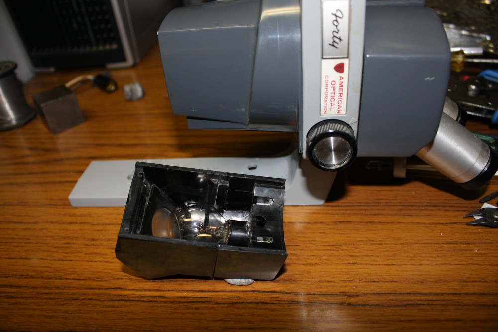
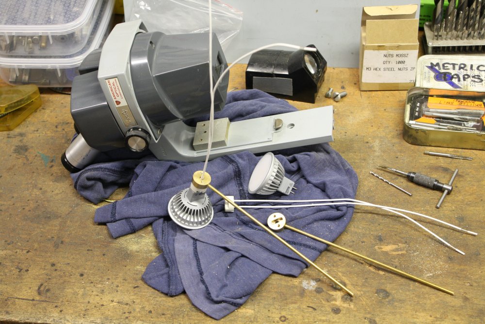
Meanwhile I've had this old Americal Optical 'Forty' for nearly a year now, but it was unusable due to multiple faults.
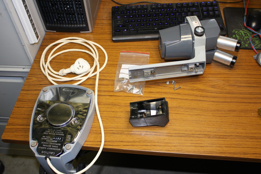
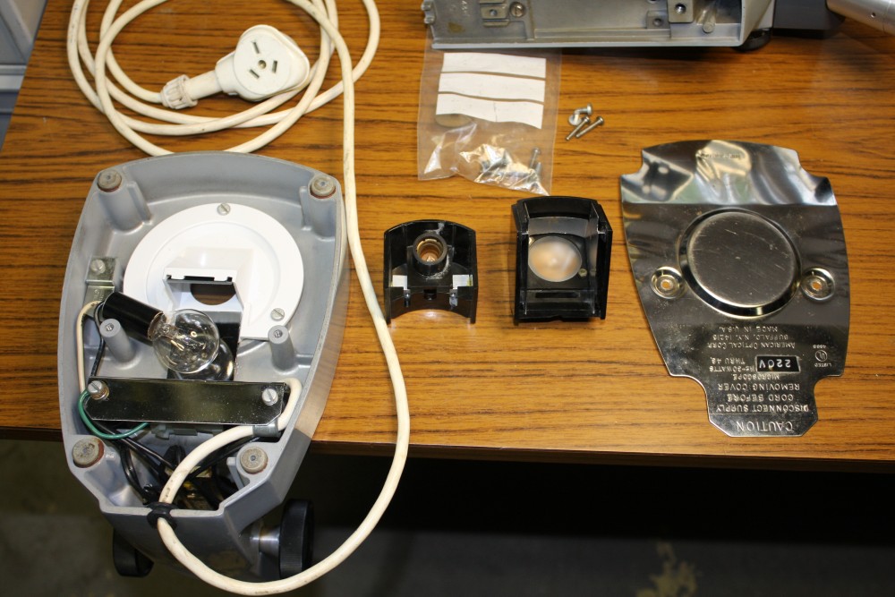
There's supposed to be top and bottom lighting, but the bakelite body of the top-light was cracked into pieces and missing the globe. The bottom light globe was present, but blown. Being made for USA use, the screw-base globe sockets were a small diameter for 110Vac globes. For Australia it had 240V globes fitted, but they are unobtainium.
The height adjustment knobs were loose, the focus adjustment stiff, a glass cover on the working-end of the optics was floating free, and the whole thing was very dirty.
A while ago I'd glued the cracked top-illuminator casing back together, and made some threaded inserts that spread the pressure of the securing screws over more area, hopefully to prevent it breaking again.
But then I'd been unable to find a new globe to fit it. Besides, it seemed a dumb thing to buy - a filament globe, that would get very hot and provide at best fairly weak lighting. But I was too busy to want to begin the improvised mods needed to convert it to LED illumination.
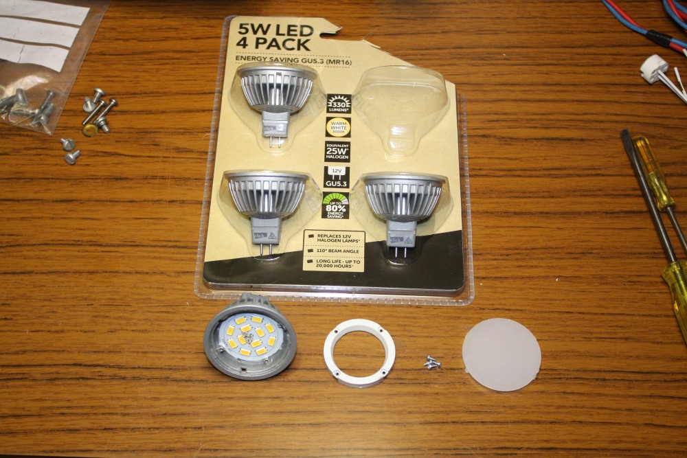
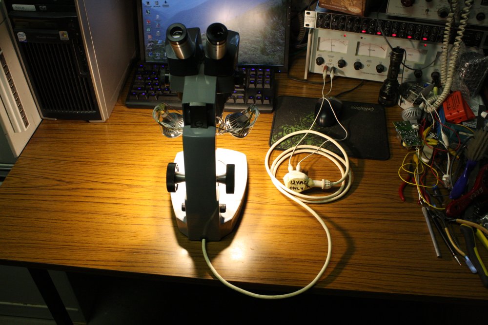
Then just after Christmas while at the hardware store I saw a cheap deal on 4-packs of 5 Watt LED lights intended for replacing 12V halogen reflector downlights. Which reminded me of the microscope. So I bought a pack ($20), some lamp connector bases, and a small mains to 12V halogen inverter that only cost $9. With fingers crossed they'd be suitable. I wasn't sure these could be made to fit the microscope, but figured I could use them elsewhere if they didn't. Cheap enough, and the LED lights claimed to work with "12Vac".
Ha ha ha... my mistake number one. Can you see the problem?
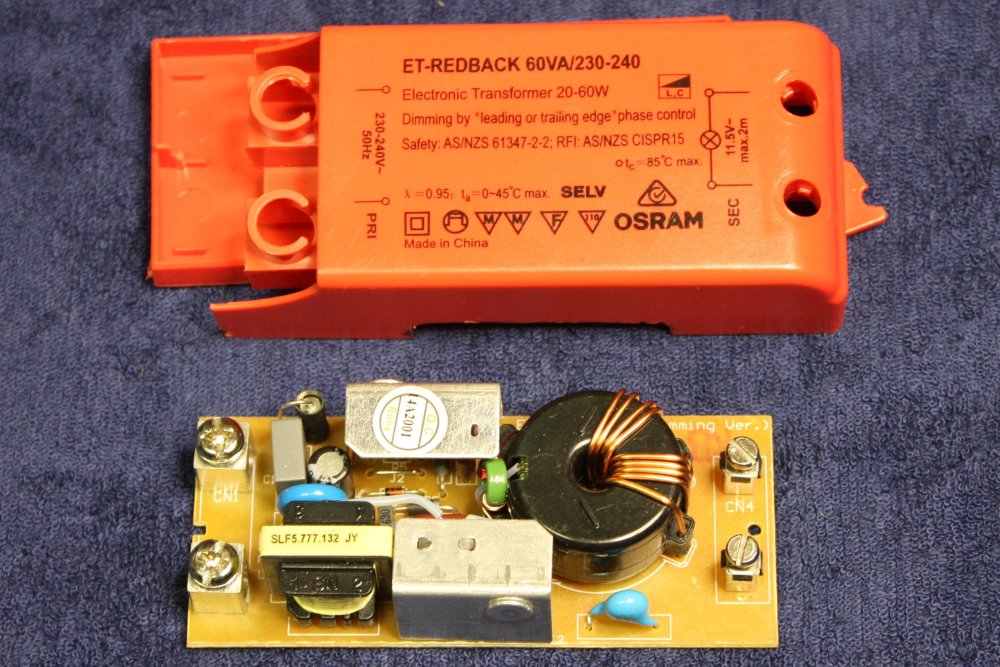
What can I say? It was a whim purchase, that I didn't consider carefully at all. Only much later, reading the fine print on the back of the downlights bubble pack, I notice it does say "Designed for use with 12Vac electromagnetic transformers only." At least I did also buy some plain tungsten halogen 20W bi-pin lamp bulbs 'just in case'.
 |
 |
 |
 |
 |
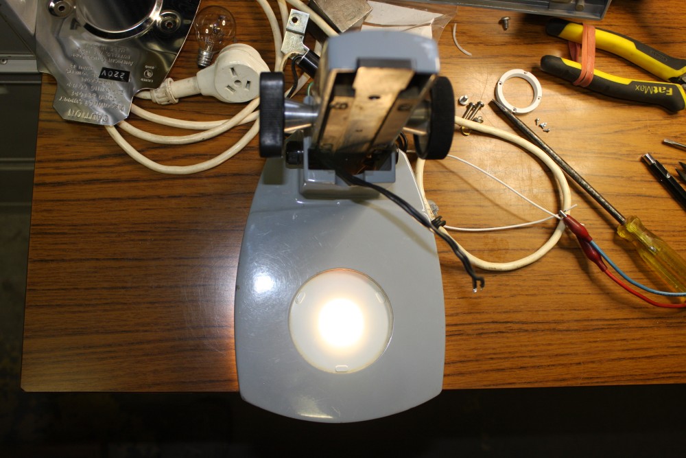
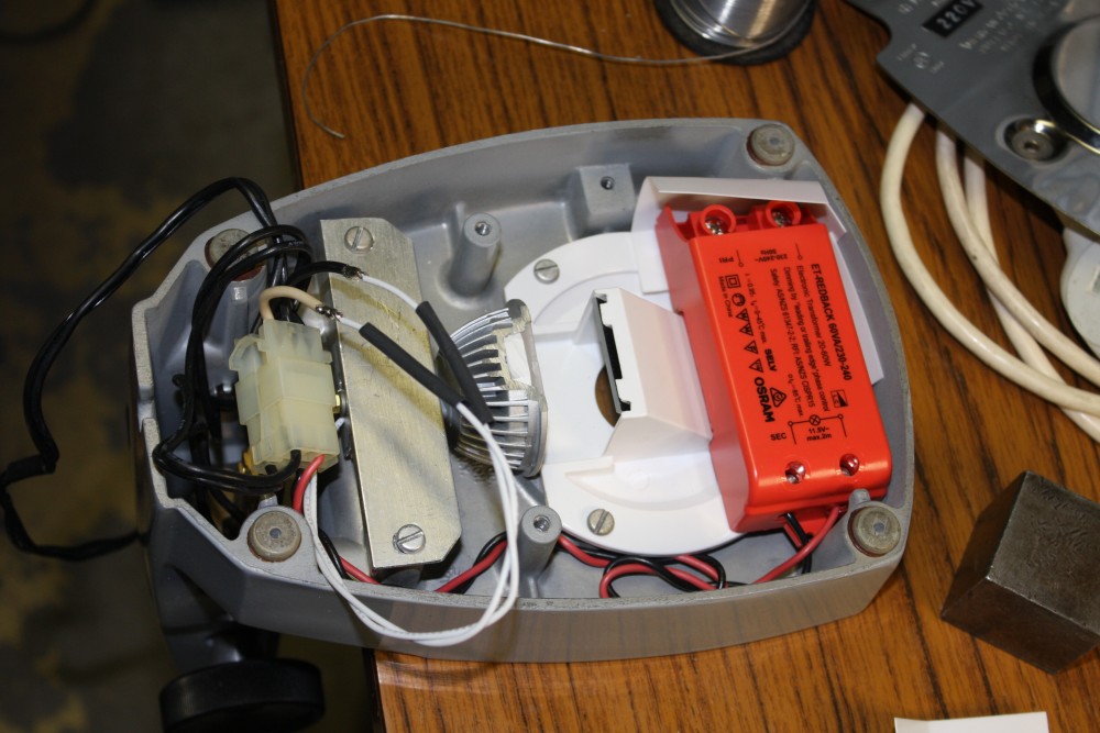
The plan was to first install the LED lights, then see if the inverter would fit into the microscope base as well. I figured that if it didn't, I could use an external low voltage supply. The first thing I tried was one of the LED lights on 12V DC from a bench power supply, and that worked fine. I hadn't expected the LED light to care whether its supply was AC or DC, and it doesn't.
I was curious whether the lamp base contained just a bridge rectifier, or a complete current-drive inverter, but there didn't seem to be any way to disassemble the light without destroying it. Varying the supply voltage between zero and 12VDC while watching the light output and current draw indicates it is some kind of regulated inverter. But I won't be getting a look inside till after one of the lamps dies.
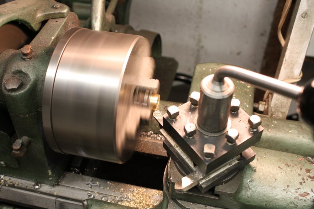
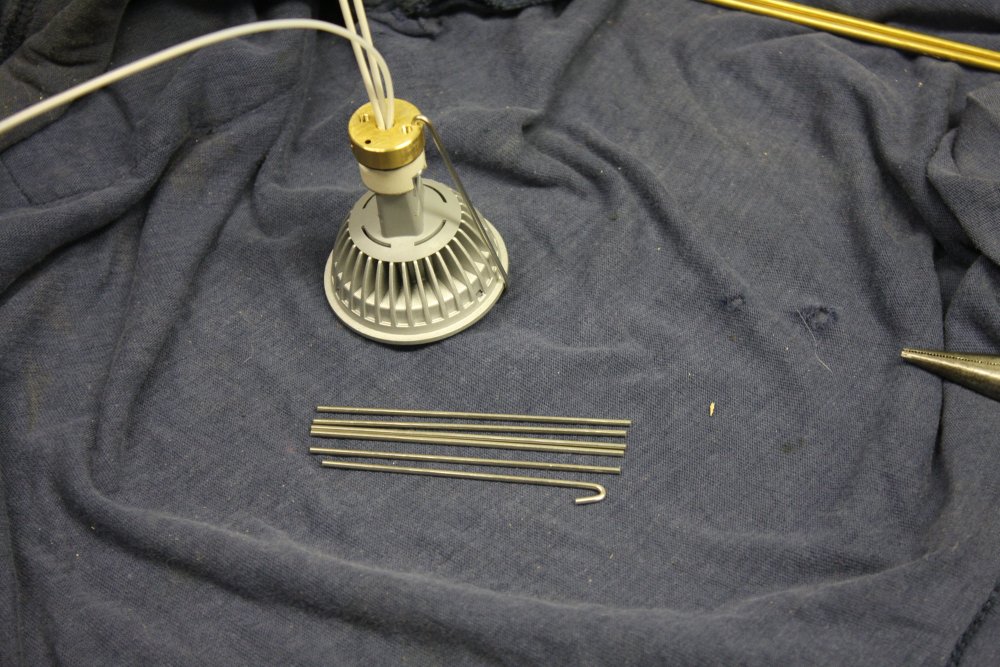
As to whether one of these LED lamps could be fitted into the base, obviously in the lamp's original form it definitely would not. The lamp diameter is greater than the microscope base thickness. Could the lamp be cut down in size?
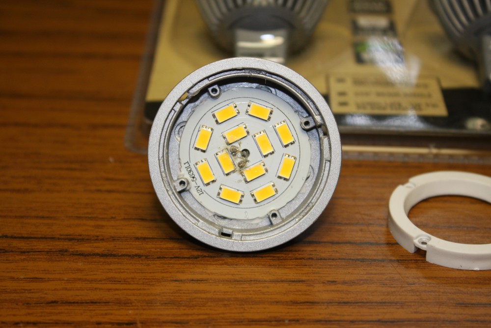
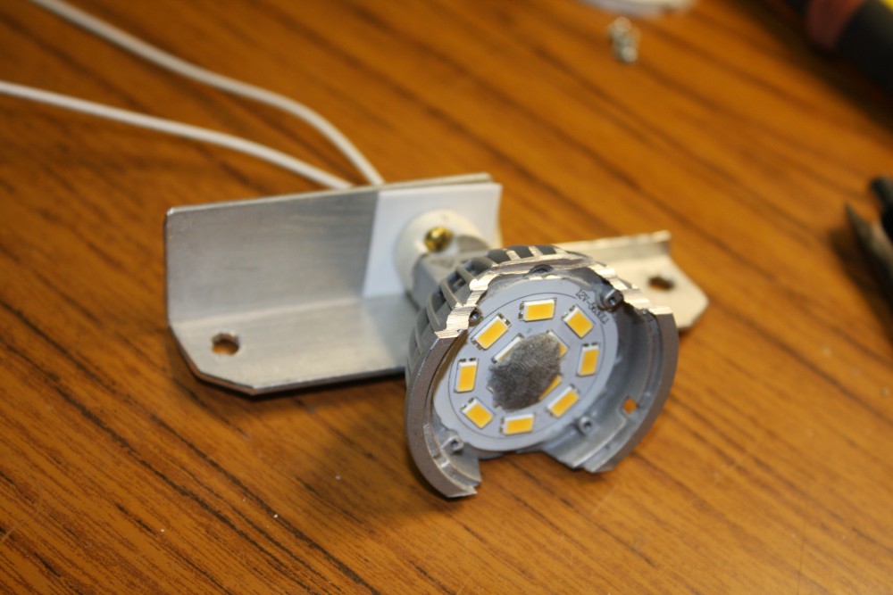
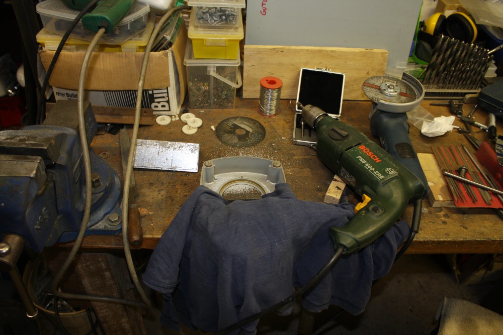
It sure could! The lamp body (which acts as a heat radiator too) is made of soft diecast alloy, and an aluminium cutting disk in a grinder goes through it like slicing a tomato with a sharp knife.
The 'circuit board' carrying the LEDs is actually a sheet of aluminium with conductive traces laid over a thin insulating layer, then a paint solder-resist on top. The 'circuit' aluminium disk is glued to the lamp body with silicone rubber glue, and would not come off easily. I didn't see any reason to force it free, so left it. Some of the tracks come very close to the edge of the disk, so care was needed to not cut too far into the light with the grinder.
 |
 |
 |
 |
 |
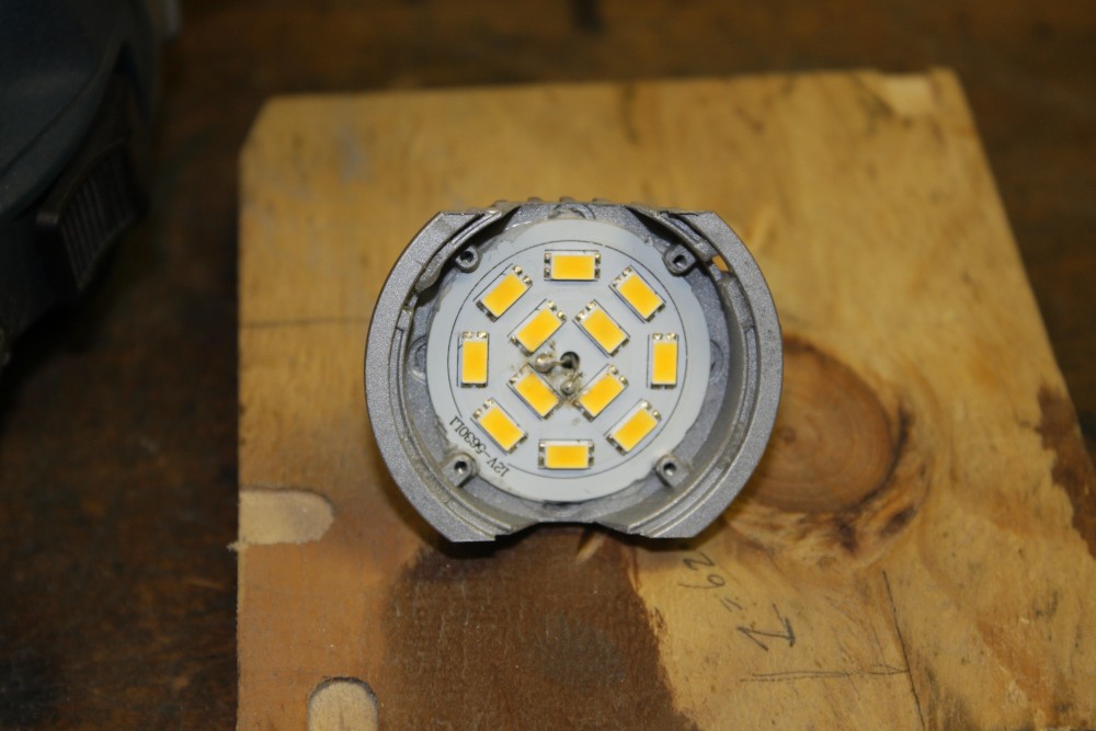
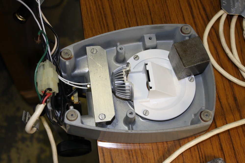
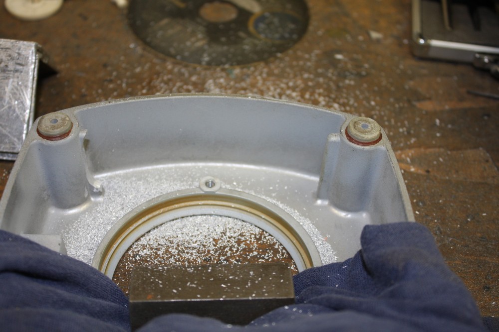
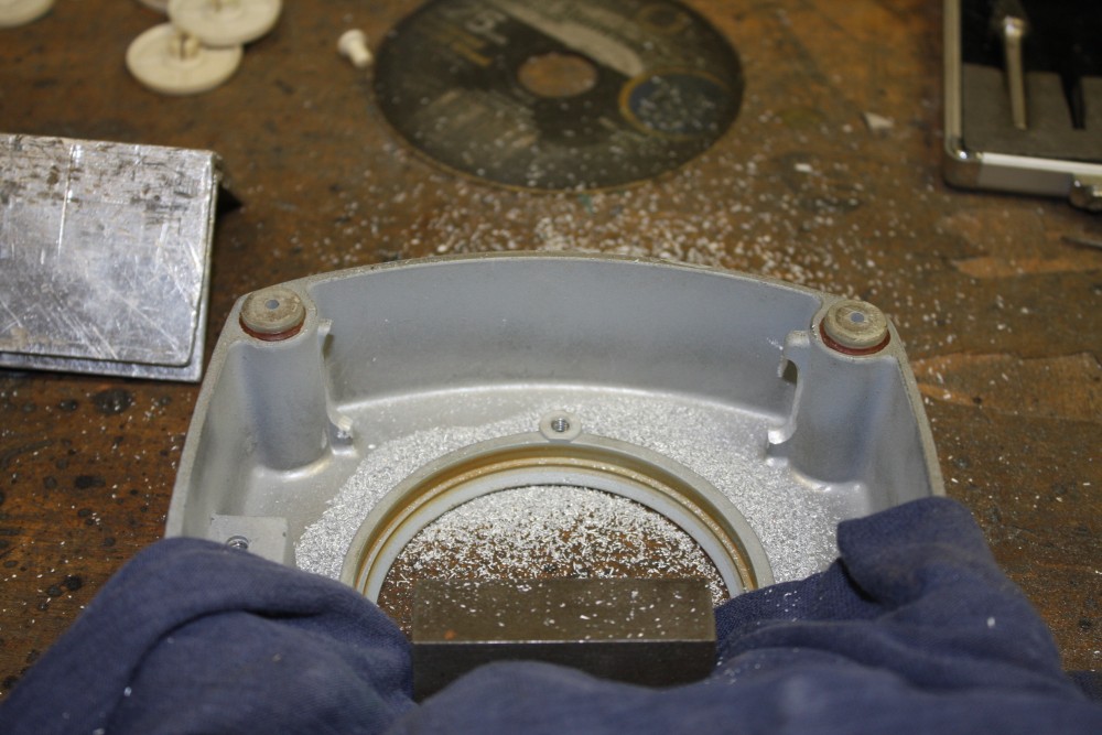
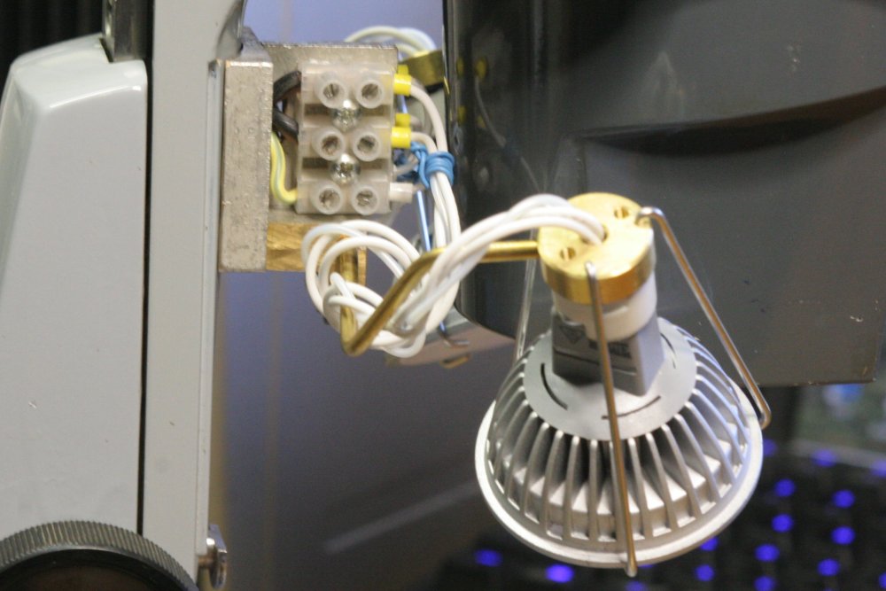
The shape in the microscope base which the lamp should fit against is a curved lip, so careful incremental grinder-cutting was required to get close enough. To mount the light, I cut a piece of aluminium L section to fit the mounting posts that previously held the metal reflector for the old globe. In the last pic the gray blob at the center of the LED array is a bit of old blu-tak I'd put there temporarily to stop metal filings getting into the base of the lamp. The electronics is down there in that inaccessible space.
The connector bases for two-prong halogen lights are made of porcelain, so are quite brittle. To avoid breakage I used a shim of high melting point plastic between the ceramic and the metal bracket. The screws are only lightly tightened.
 |
 |
 |
 |
 |
 |
 |
 |
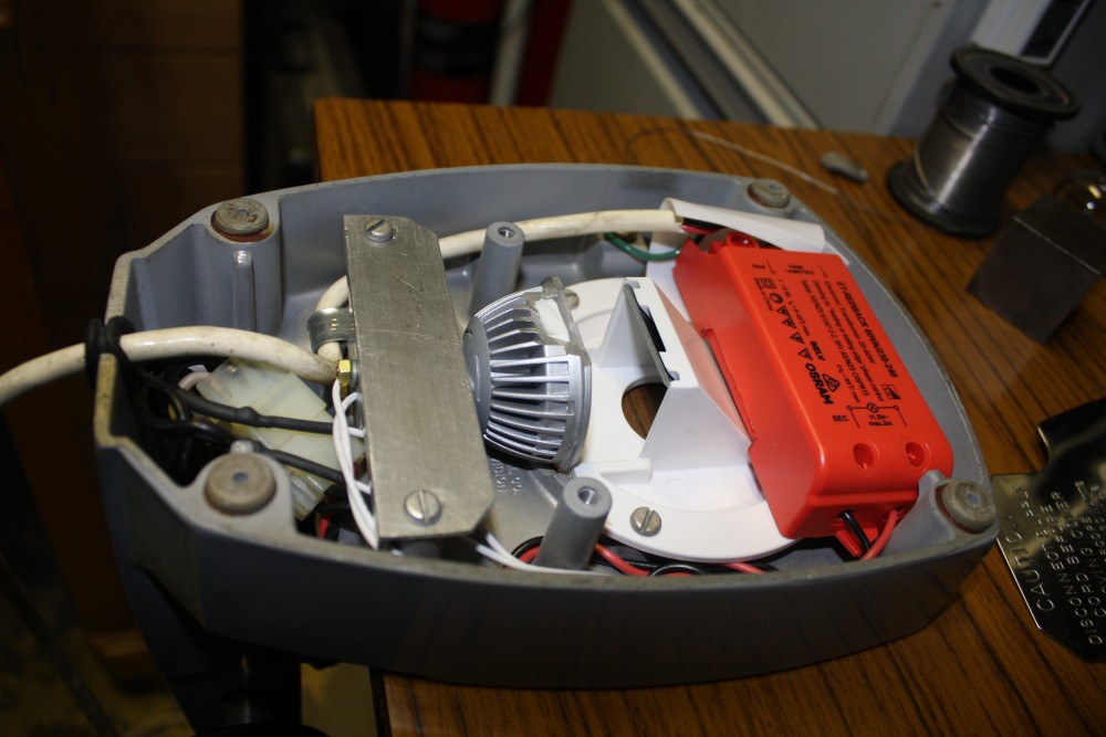 |
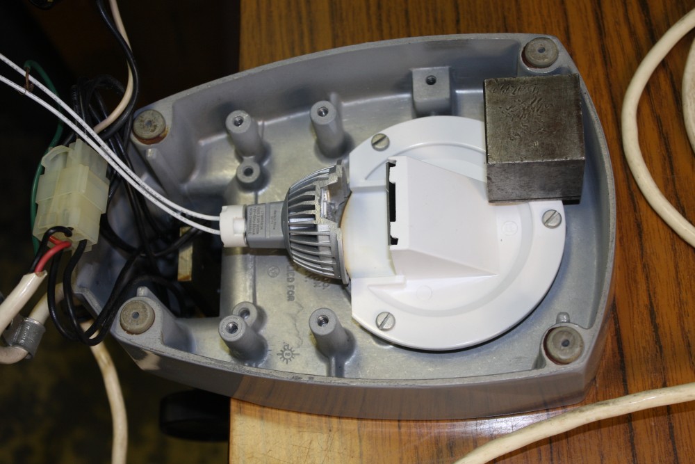
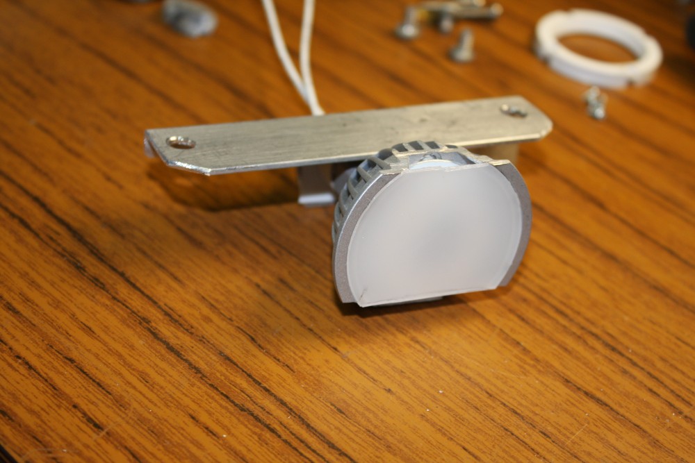
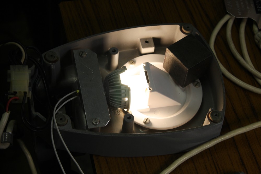
With the diffuser cut to fit the sliced light, and the mounting complete, the next question was whether the downlight inverter I'd bought could be used, and more importanly, could it be made to fit. I briefly tried the inverter running a couple of the lamps, and it seemed to work fine. I'm ashamed to say it still didn't occur to me to check (with a scope) whether 'seemed to work fine' was actually true. When a lamp lights up, one tends to assume it's working.
Investigating the mechanical fit it turned out that it did, but only just. To get it in I had to remove some metal from the base (using a die grinder bit in a drill), and pare some of the plastic off the inverter. Mains isolation insulation is still satisfactory.
 |
 |
 |
 |
 |
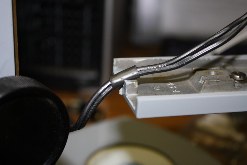
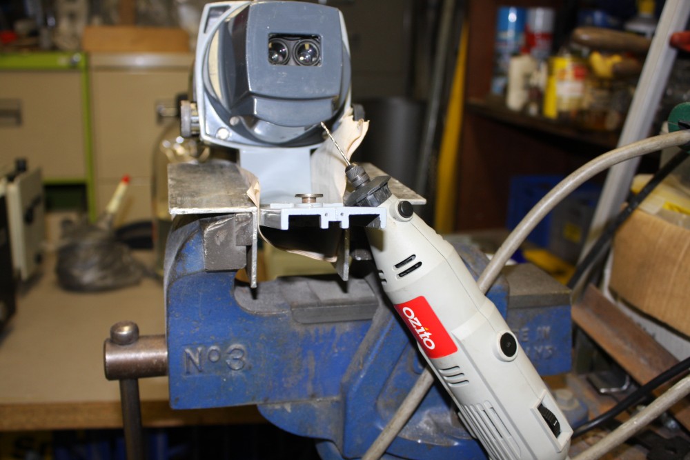
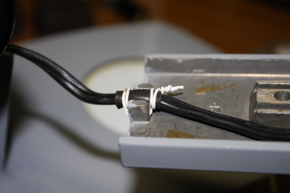
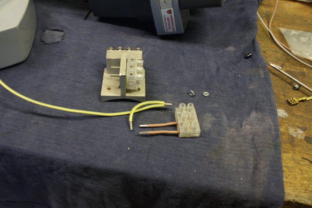
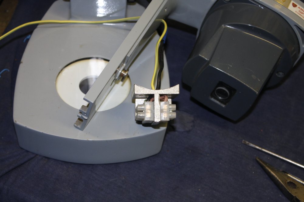
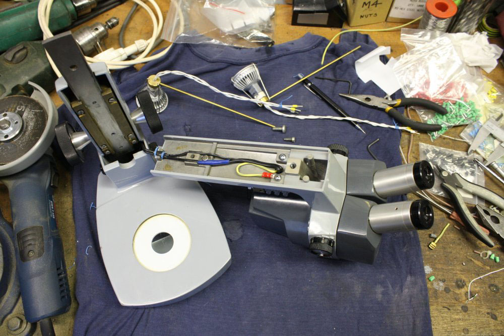
And so onwards, to the top-lighting. First problem was that the twin-8 wires passing up inside the vertical slide assembly are supposed to be clamped between the slide and diecast frame when it's all screwed together. But getting them to sit in their slots while assembling, is painfully fiddly. Some way to hold them in place during assembly would be a great help.
The solution was to drill a couple of small holes through the saddle, and bind the cable to them. First thing to hand was some insulated wire from a cat-5 cable. I save bits of old cat-5 cable, as the fine solid-core wires make good general purpose ties. They are easy to pull out of lengths of cable due to the loose, thin sheath.
The last pic is the original bakelite lamp and lense housing. I've decided to simply abandon that. Trying the microscope while experimenting with one or two of the LED downlights in various positions, I'd found that using two of them close by either side of the microscope body gave excellent results. So that's what I'll do — hopefully in a way that allows for adjustable positioning of the lamps.
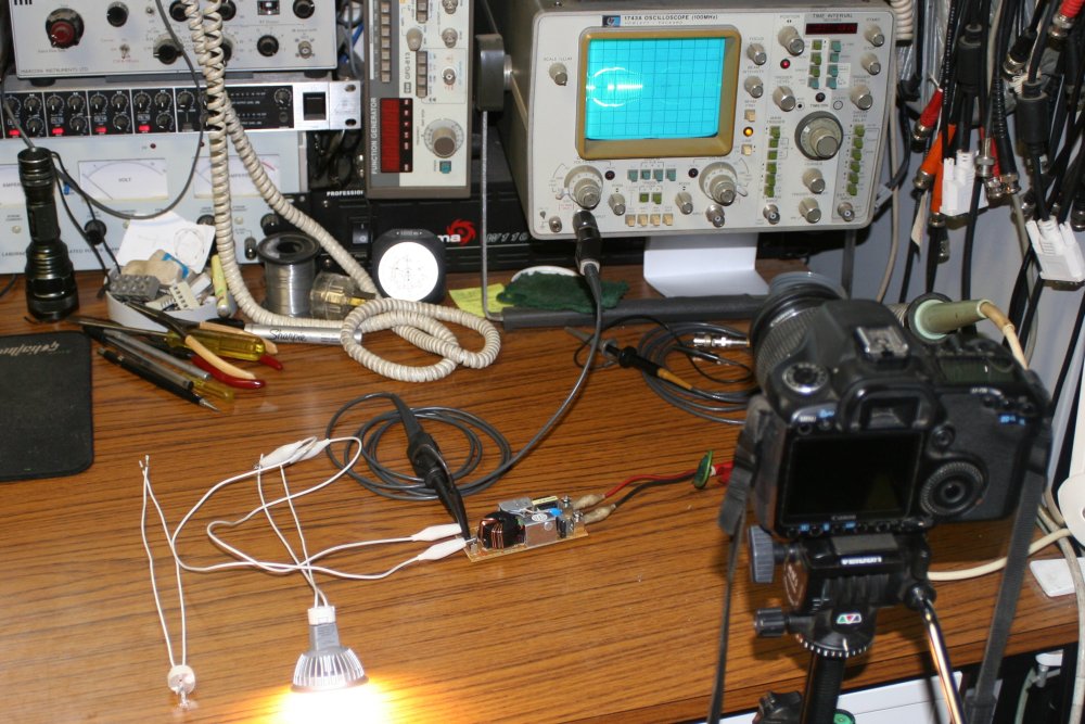
During those trials of the top-lighting lamps, I'd been using the microscope base with the installed inverter to power all the lamps. It still seemed to be working fine, powering three of the 5W lamps — which was well within the stated 60W rating of the inverter. However at this point it finally occured to me to look at the "12V AC" inverter output with a scope. What I should have done first.
Arrrgh!
 |
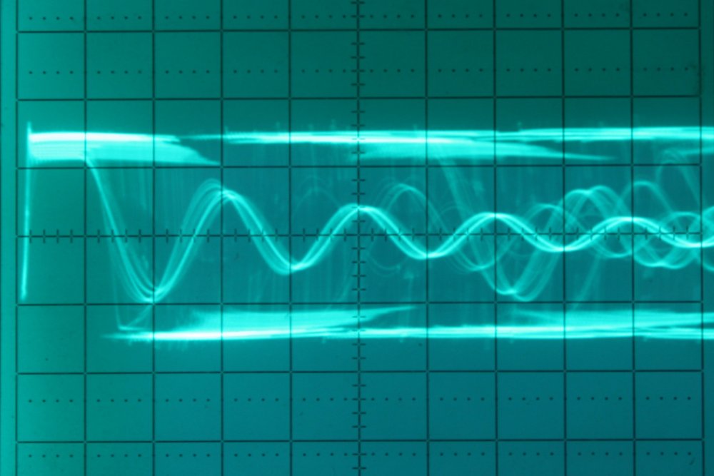 |
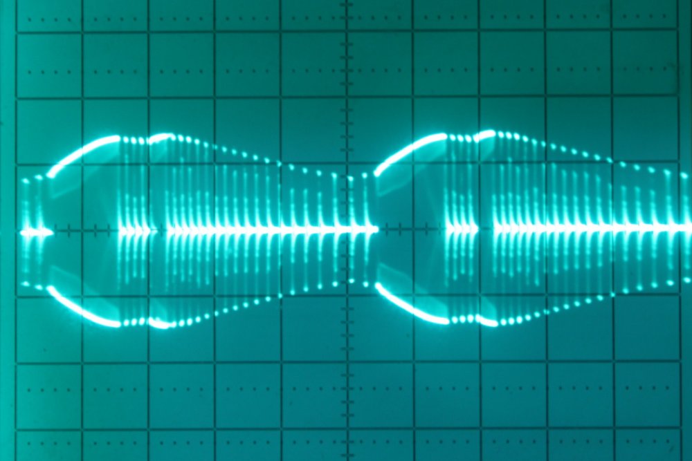
Ohhhh, that's horrible! At left the sweep is 2mS/div, showing the overall power envelope. The general peaks are synchronous with the 50Hz mains, but the fine detail waveform is an unstable high frequency mess. At right the sweep is 5uS/div, and triggering on a mess like that is hopeless, but it shows the kind of stuff going on. Roughly 40KHz major oscillation (intermittently), plus 100KHz barely damped ringing in the gaps between oscillator drive.
The moment I saw this I felt stupid — I had known but was ignoring that these lamps must have small switch-mode inverters inside, and of course the large red mains inverter won't be outputting nice 50Hz 12Vac. Why didn't I realise while standing in Bunnings, that connecting them together very likely wouldn't work? Hmmm.... Idiot.
 |
 |
 |
 |
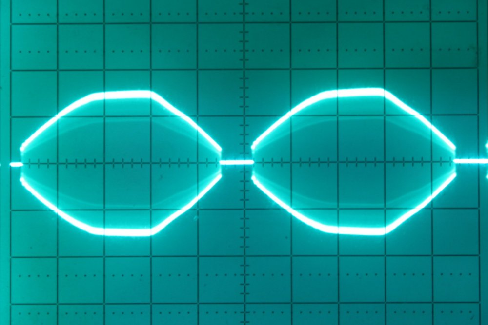
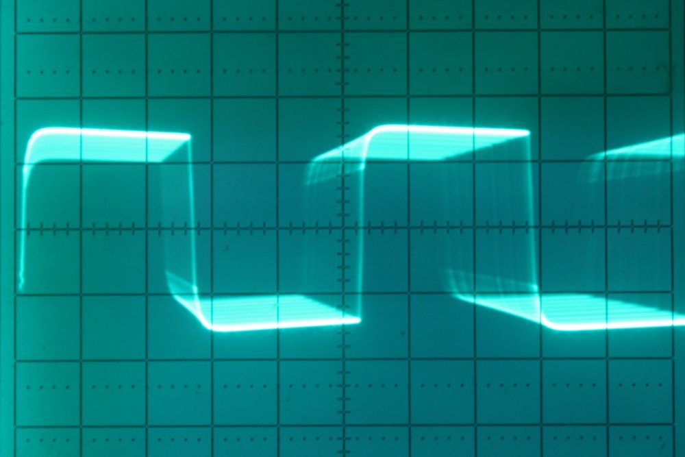
The same settings as the messy waveforms, but with an ordinary 12V halogen light bulb as a load on the inverter. This is how the supply is supposed to operate, with a passive resistance as load. It generates a roughly 40KHz square wave, with amplitude envelope tracking the mains voltage. No primary side capacitor smoothing, because who needs it?
With some experimentation I found that the inverter behaves itself and produces the correct output waveform so long as there's at least one halogen bulb as a load. Then it remains stable even with three of the LED downlights in addition.
But that was moot, since I doubt the input circuitry of the LED lamps will be happy running on a 40 KHz square wave. They seem to run, but for how long? Also they seem to run hotter to the touch on the 40 KHz drive, than on DC or 50Hz AC. Not surprisingly.
Oh well. So I can't use that red inverter after all. Too bad I already hacked it to fit. But no matter, it was only $9. For now I'll run the lamps on externally supplied 12V AC/DC, while seeing if I can find a small mains to 12V DC power supply that fits inside the microscope base.
I wonder how many people make that easy mistake, fit this combination of lamps and inverter supply in the their kitchen ceiling, then wonder why the lamps keep failing (or their house burns down)?
Constructing the Top Lights
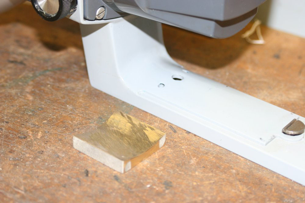
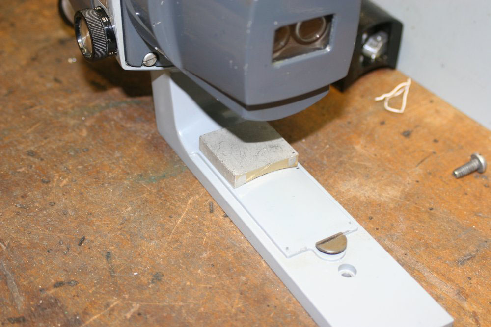
I didn't want to make any permanent change to the exterior of the scope. To attach the lights, I wanted to use existing structures unhacked. Other than that, I don't really care how it looks so long as it works.The only mounting point available is where the original top-light used to be. There are two screw holes here, but with the complication that the frame surface is a compound curve — cylindrical, but with varying radius of curvature. Perhaps something cast in epoxy against the surface would have worked, but I'm old fashioned and like stable metal. So I decided to do this in brass.
 |
 |
 |
 |
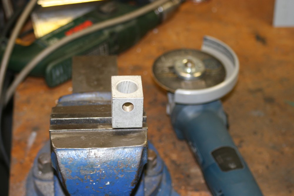
I have plenty of round bar brass stock, but did I have any flat bar? No. Hunting through the brass scrap bin I found a large terminal block from a heavy circuit breaker. This should have enough brass for what I need.
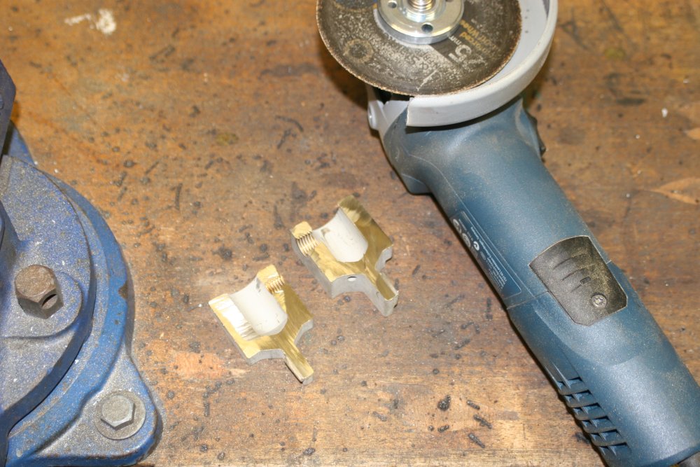
A thin cutting disk in the angle grinder makes roughly cutting pieces from the block easy. Shaping the complex curve to fit the microscope stem surface took a bit longer and lots of incremental fit-and-see, cut a bit more, cycles.
 |
 |
 |
 |
 |
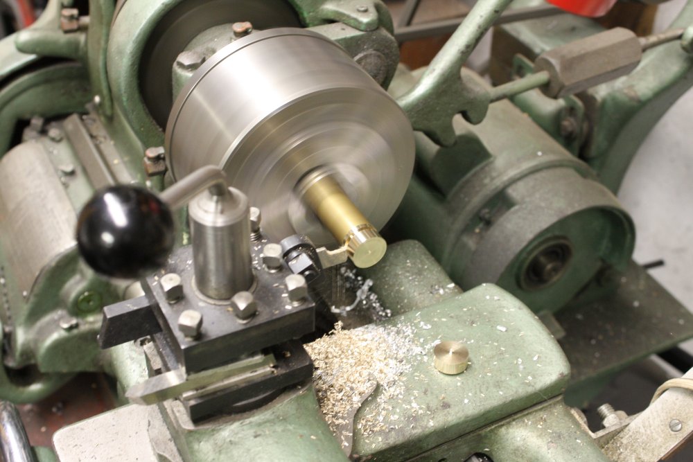
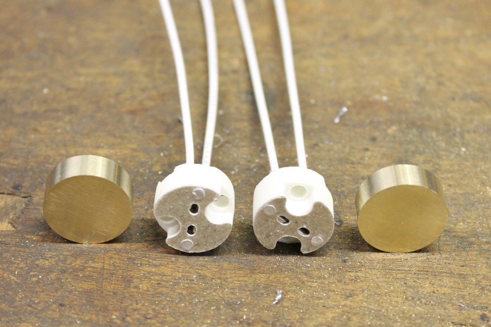
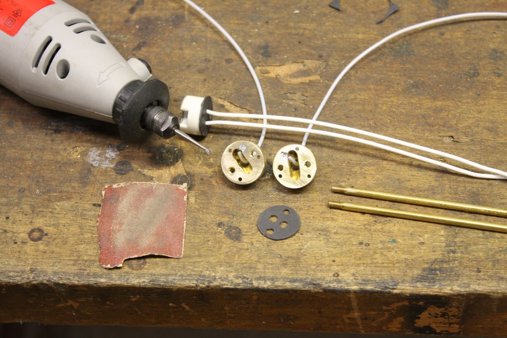
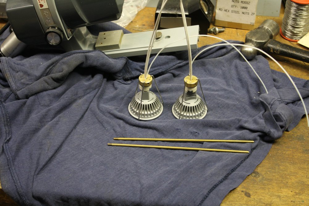
With a base anchor point assured, next was to work out how to mount the lamps. The following was very much a case of winging it. No prior paper design at all. I started off by making a couple of brass disks. The idea is that everything will attach to these - the lamp sockets, mounting bar, and retaining clips for the light.
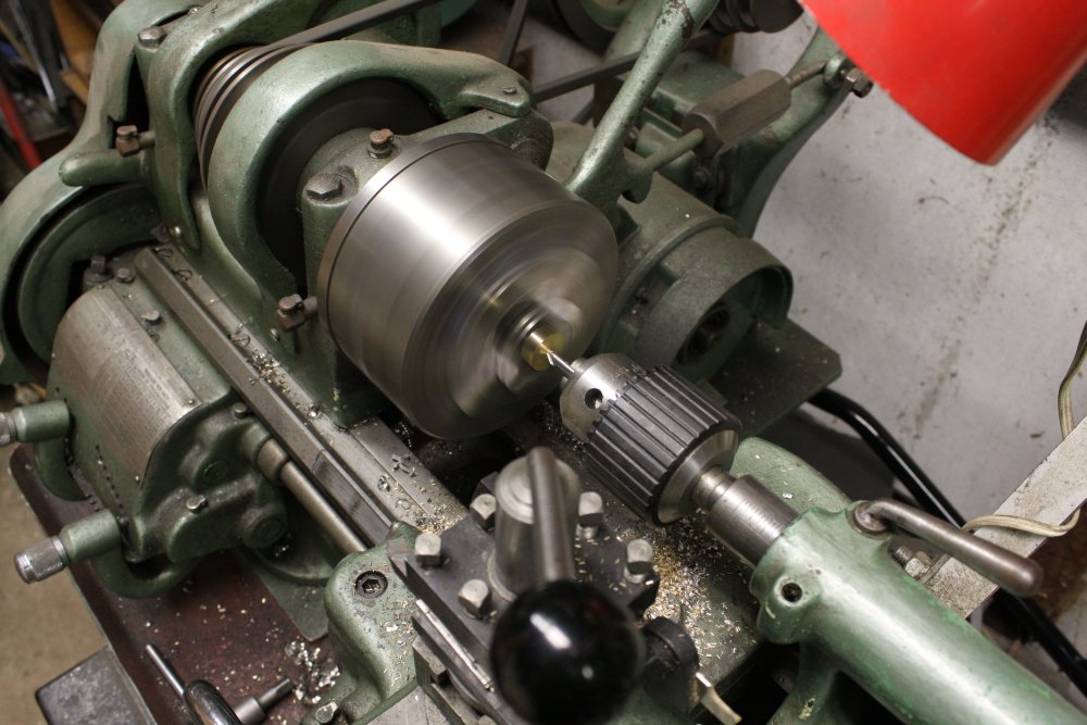
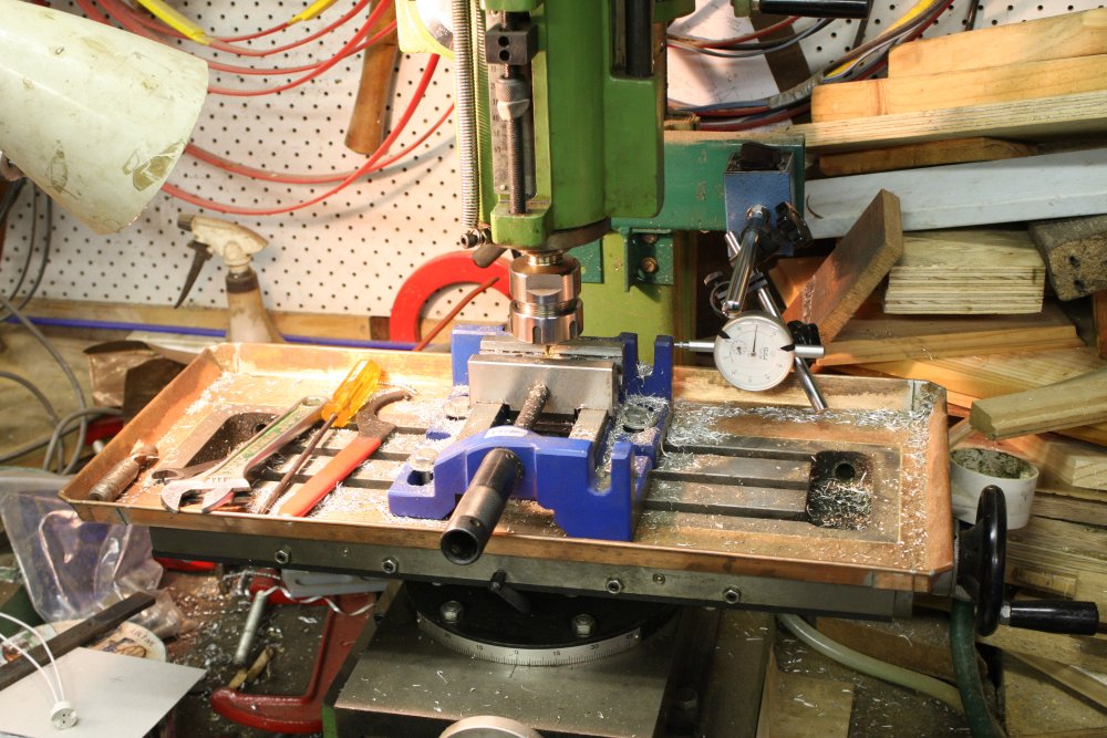
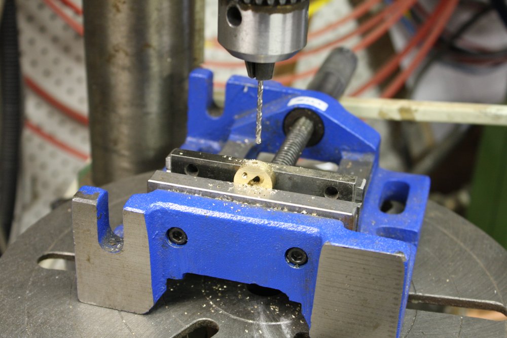
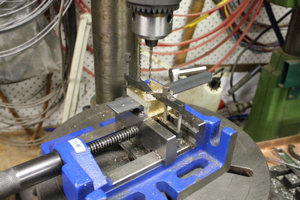
First task is to make the holes for routing the wires. As it turned out, with the brass disk down in the vice and a small cutting bit in the mill to make those slots, I totally could not see the cutting bit at work. So had to rely entirely on a dial gauge. As you can see, I must have miscounted needle turns a bit on the dial, since the slots are slightly off center. Doesn't matter, I'd allowed clearance for errors.
 |
 |
 |
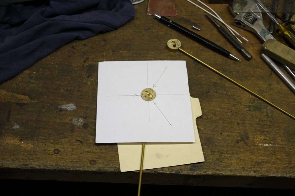 |
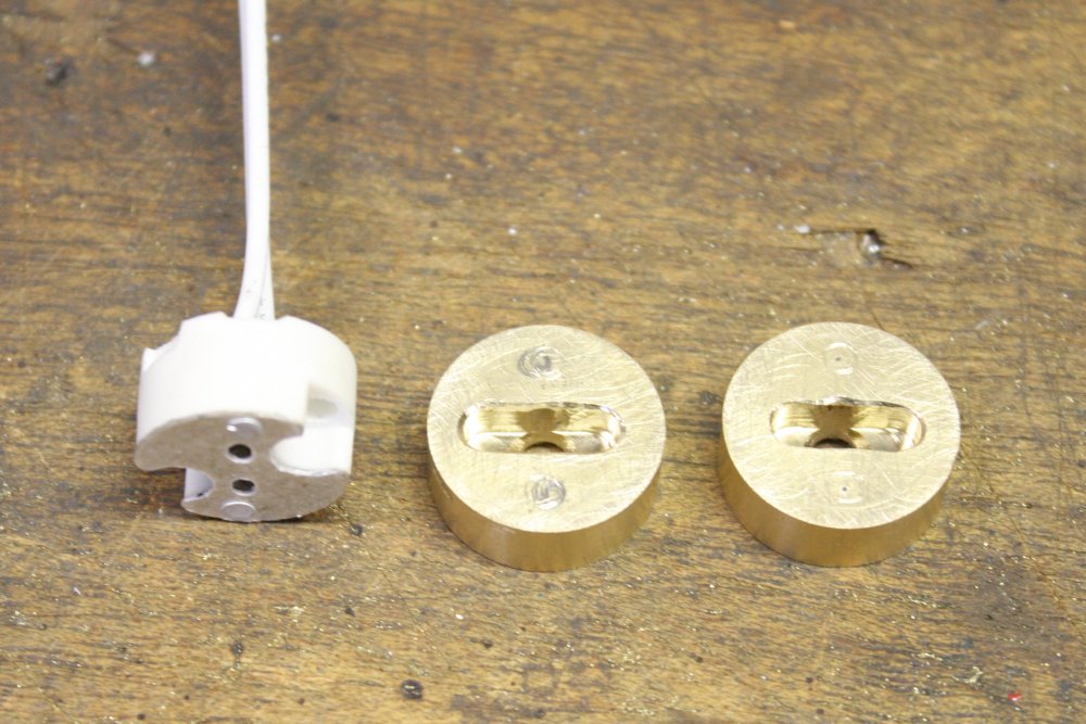
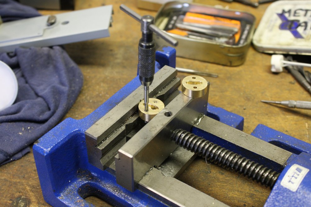
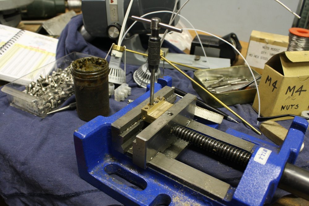
The holes for the lamp socket screws were a worry. I like to transfer drill holes, to avoid any chance of error. But with the lamp sockets being fragile ceramic that wasn't possible. Also, the tapping drill for M3 screws is 2.5mm, smaller than the holes in the ceramic. The drill would drift around in the hole even if it didn't break the ceramic. There was no avoiding having to mark the holes through the sockets with a scriber, center punch to the marks, drill the holes and cross fingers. It worked; after tapping for M3 screws both pieces fit well, with no binding of the screws against the ceramic hole sides.
Another hole from the side, to be tapped for the threaded end of a brass rod (actually bronze welding rod) as a mounting bar.
Lastly, marking the three holes for springy lamp retaining clips.
 |
 |
 |
 |
 |
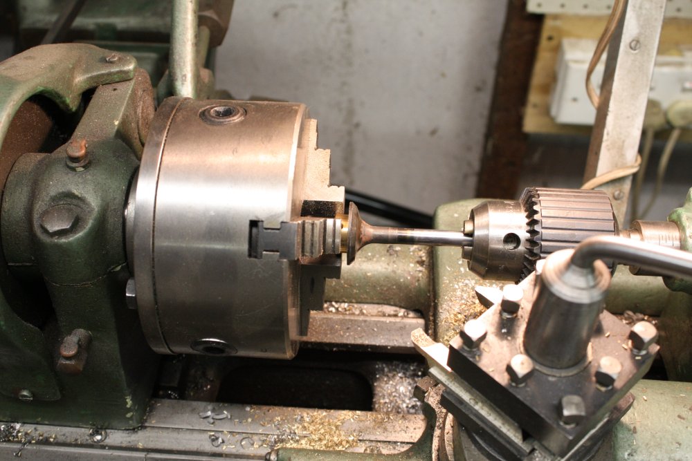
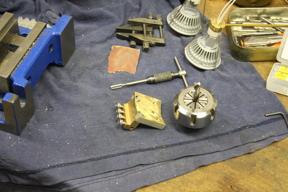
With all the major work done on the disks, there were still a couple of minor things, like putting a little bevel on the edges. How do you fix a small object in the lathe chuck with no axis tilt? Answer, by pressing it against a known aligned surface. In this case made from an old car engine valve with the end face turned flat.
In pic 3 I'd cut a small slot in the disk face to allow soldering in a third wire, for a 'chassis ground' connection. Not really needed in normal use, but just in case I ever wanted to use the lamps free, with the mounting bar detached from the microscope body.
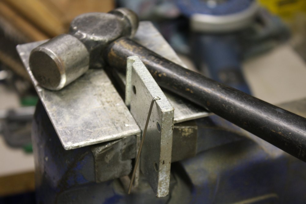
Pics 4 & 5 are of the lamp retaining clips being made. A piece of scrap steel with a small hole drilled near an edge is used for forming the tight bend in the wires repeatably. The wires are cut from a stainless steel TIG welding filler rod.
 |
 |
 |
 |
 |
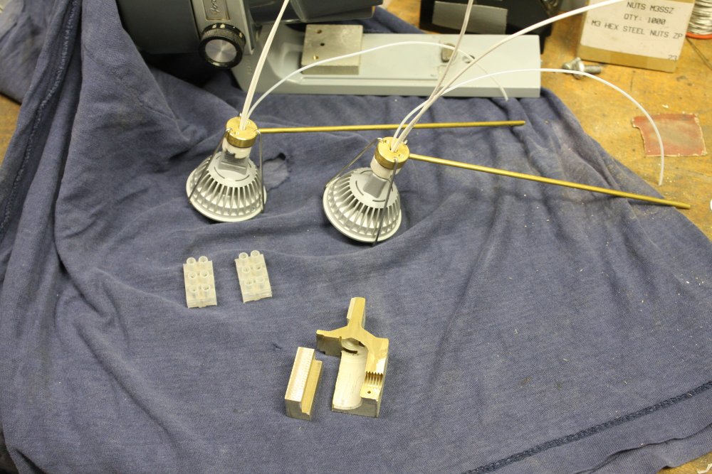
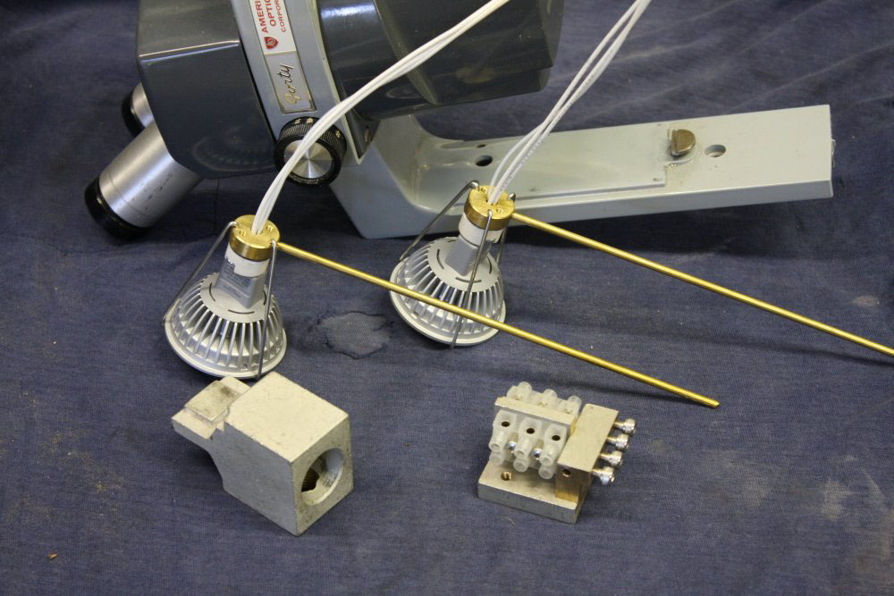
With the lamps and mounting rods complete, that left how to attach the rods to that brass block on the microscope stem, and connect the wiring. I wanted the lamps easily removable, and position adjustable fairly easily.
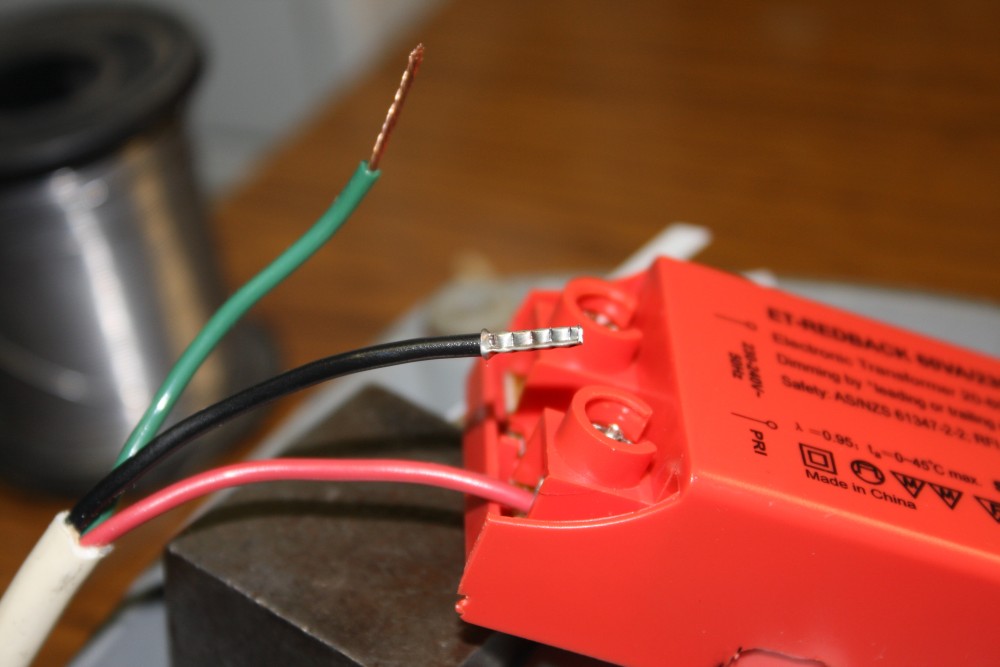
For the wires that meant terminal blocks, and bootlace ferrules on the wire ends. The terminal screws had to be accessible from the sides, and the screws securing the lamp mounting bars also had to be accessible. That greatly constrained the possibilities. In fact I could only see one configuration that would work. For this I needed some more chunks of brass, also cut from the original terminal block.
Firstly an L-shaped piece to secure the lamp mounting bars, and allowing good solid M4 machine screws as clamps.
 |
 |
 |
 |
 |
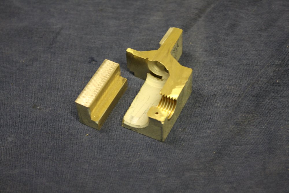
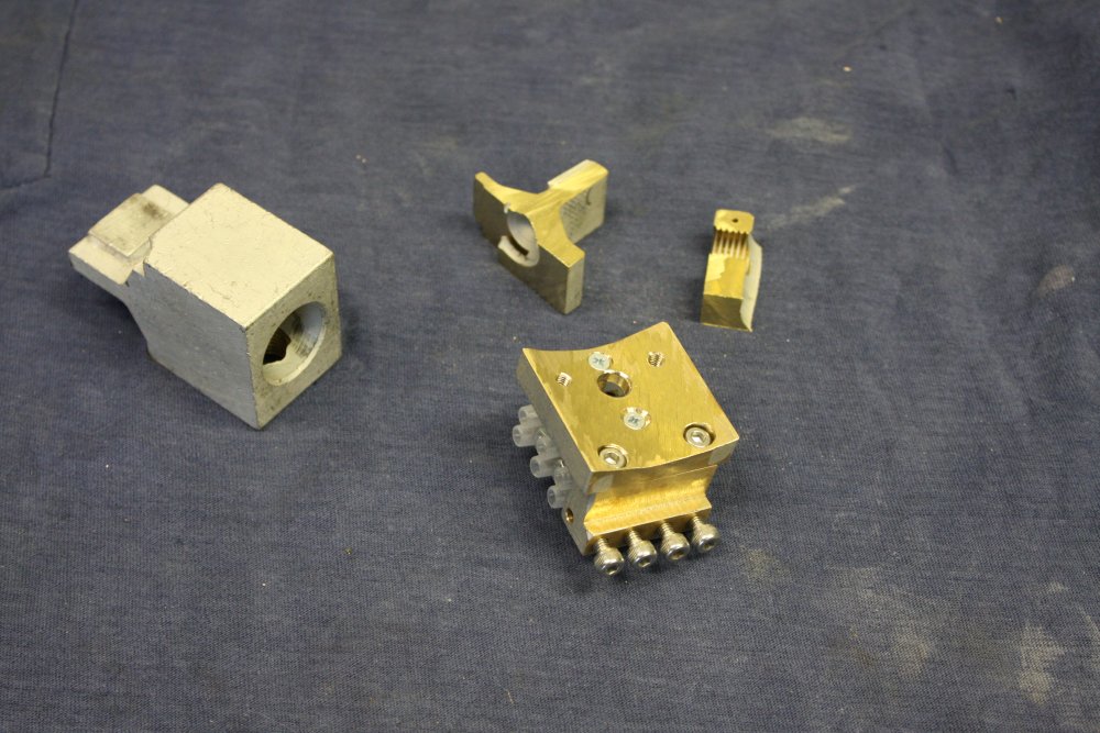
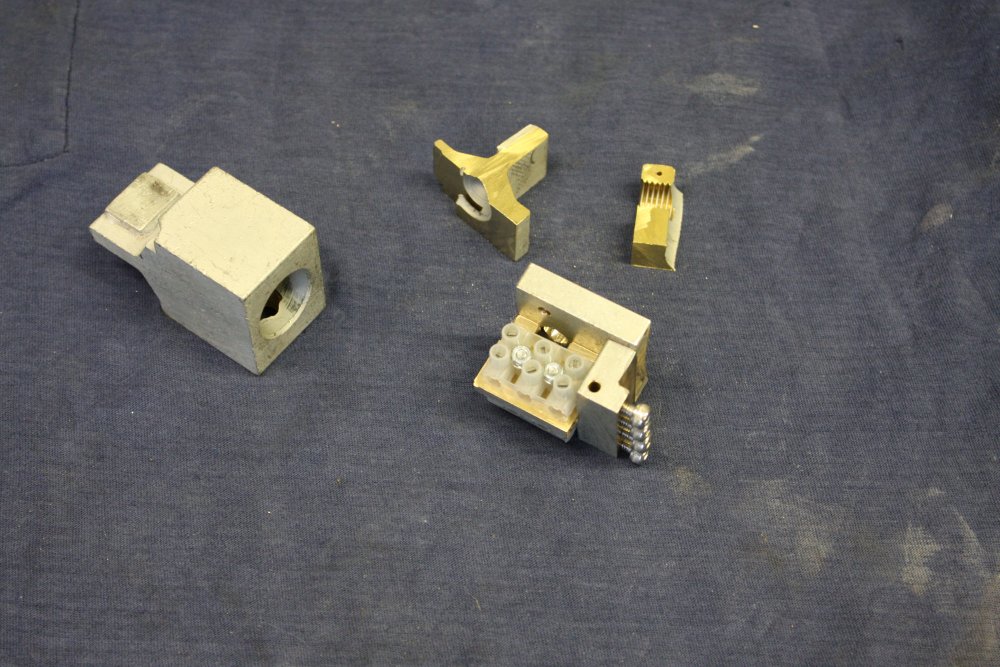
Pic 1 shows that mounted. To cut the square-edged recess holes for the machine screw heads, I'd ground an old drill bit end flat, then added a little camber for the cutting edges. Used in the mill it worked fine.
Pic 2 was me working out if the remaining piece of brass from the old chunk had enough left for a mounting slab for the terminal blocks. Turns out it did — just. Pics 3 & 4 are of cutting it free. It was then milled to a clean finish and mounted (last pic.)
 |
 |
 |
 |
 |
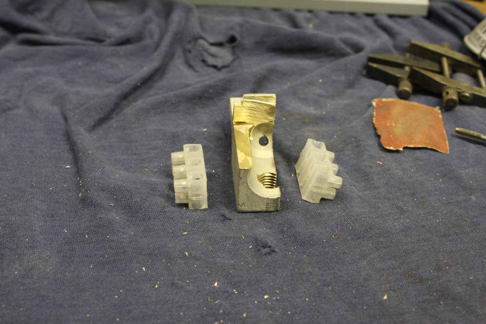
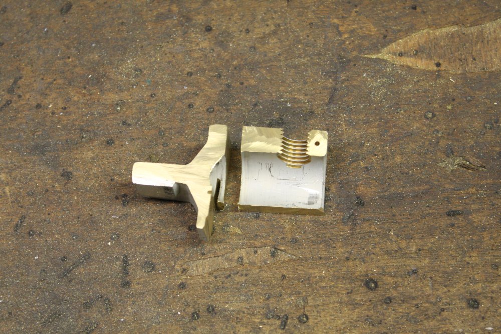
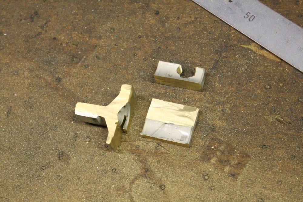
Done. In pics 1 & 2, a piece of scrap plated brass as on the left, had become the finished assembly and couple of scrap remainders on the right. The rest was wiring it up.
 |
 |
 |
 |
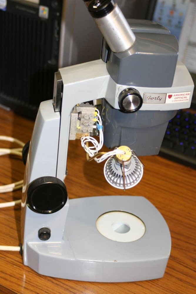
Working! For the moment it needs an external 12V supply, but hopefully something suitable that fits inside will turn up. The top lamps are not pretty, I know. But they are plenty bright enough. Too bad there's no camera facility on this microscope, so I can't demonstrate the view it gives. I like it. According to the numbers on the knob, it gives from 10x to 45x magnification. Depth of field seems to be quite good in the low magnification range, reducing to very little at 45x, as you'd expect.
Ha ha... I knew this already, but while playing with this microscope was reminded of it. NEVER look at your own fingernails and cuticles under high magnification. Most definitely don't get a scalpel and try cleaning up the horror under magnification.
No, don't!
OK, so you did. I warned you...
Now does the phrase 'flensing a decaying whale carcass' seem familiar? Cannot unsee!
Discussion at eevblog: LED-lighting an old American Optical binocular inspection microscope.