I've recently added LED lighting to two microscopes; an old 'AM Forty' and a very nice Olympus BHM.
Those worked quite well, so now it's time to try something for my old Zeiss Universal microscope.
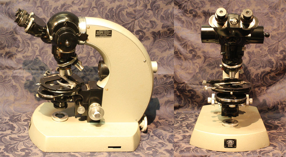
This has been sitting around here for years. It's a magnificent instrument, it came with lots of accessories and kit, and even several spare of the high pressure 50W mercury arc lights. But unfortunately it was missing the actual lamp housing and power supply, so there was no light source.
Although overall it appears to be in good shape, it is rather long in the tooth. For one thing later instruments of this line had a light color enamel, while mine is black and gray. More importantly the later model base was adapted to hold a set of light filters in the transmission illumination path. Mine doesn't have that. Nor does it have the later rear light path selection case, that allowed for transmission or reflected modes. It has a camera tube and camera, but it's a 35mm film camera, which is no use to me.
I'm not complaining though, since the whole set came free, via a good friend who later died of cancer.
The primary problem with getting this working is that the Zeiss Universal is still a much sought-after model as well as fairly rare, and so parts for them on ebay are quite expensive. When I could afford it I've been looking, but didn't have much luck finding a 50W arc lamp housing and power supply.
The method of gluing silvered foil to the inner surface of metal structures to make a light pipes/concentrator worked very well with the Olympus light source. So now I'm going to try taking it to the next level. For this microscope I want to achieve a light source that:
- Has an adjustable energy spectrum, including the ability to get a reasonably flat spectrum White light.
- Allows extending the light spectrum into the UV range, to allow fluorescence studies.
- Has adjustable power up to the range achieved with the standard high pressure mercury arc lamps, ie 50 to 100 watts.
For examining and adjusting the light spectrum achieved, I have an old but very good spectrophotometer, a Shimadzu QV-50. Or rather, two of them. They both need work, plus with some customization it should be possible to computer automate measurements using them. That's a future project. In the meantime I'm going to proceed with a multi-coloured LED high power light source, and just assume I can qualitatively optimise spectral flatness in future. Incidentally getting at least one of the spectrophotometers working is necessary for a different project, not just this microscope light.
What I'm going to attempt this time will probably require an iterative process. Which is a nice way of saying I expect a series of stuff-ups. So I'm going to write it up and post as I go, rather than wait till the project is finished or as near as.
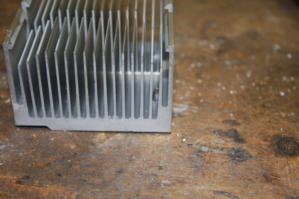
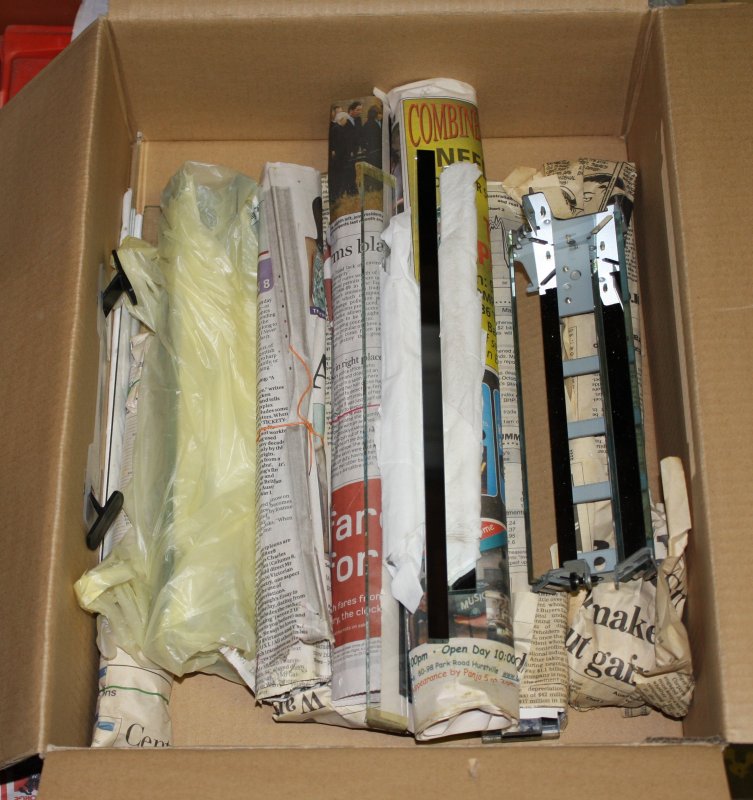
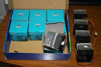 Fortunately as well as several boxes of assorted old PC fans and CPU heatsinks, I have this nice box of a dozen identical new CPU heatsink-fan assemblies. (Yes, one is not in the pic.)
It looks like the available 50 Watt LEDs would fit on these heatsinks (the ebay listings never seem to give dimensions, but they can be found elsewhere.) I don't have power vs temp rise curves for the heatsinks, but it's easier to just buy some LEDs and try them, than spend time setting up an experiment with a large metal-case power resistor bolted to one of the heatsinks and deriving that curve myself.
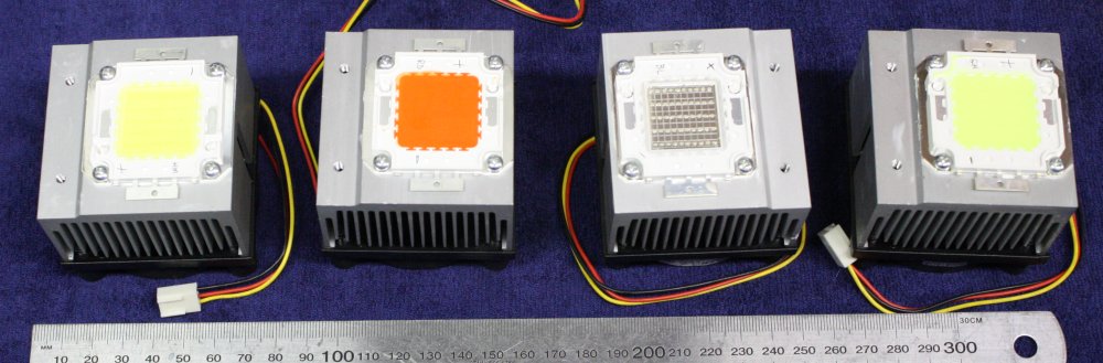
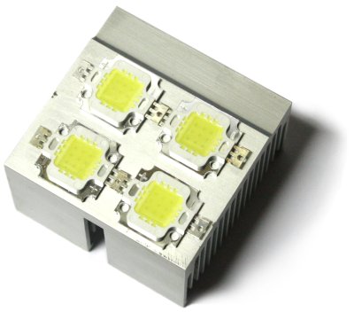
So, I ordered some 50W LEDs. One each of Cool White, Red, Green and Blue. Prices:
  Cool White    USD$2.99   AU$3.85
  Red           $3.13         4.03
  Green         $2.89         3.72
  Blue          $2.99         3.85
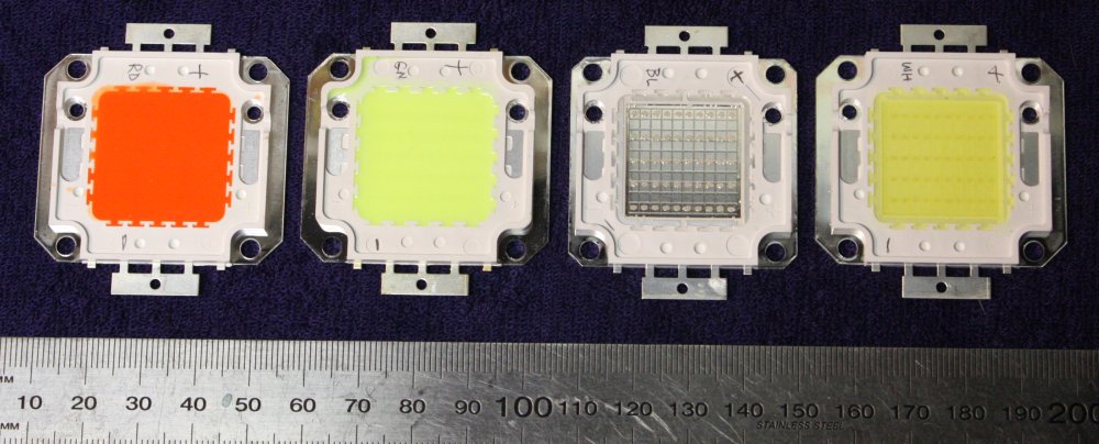
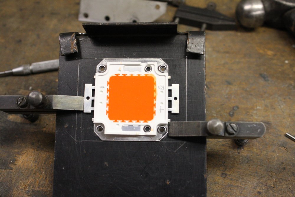
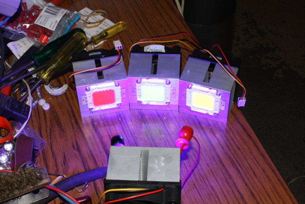
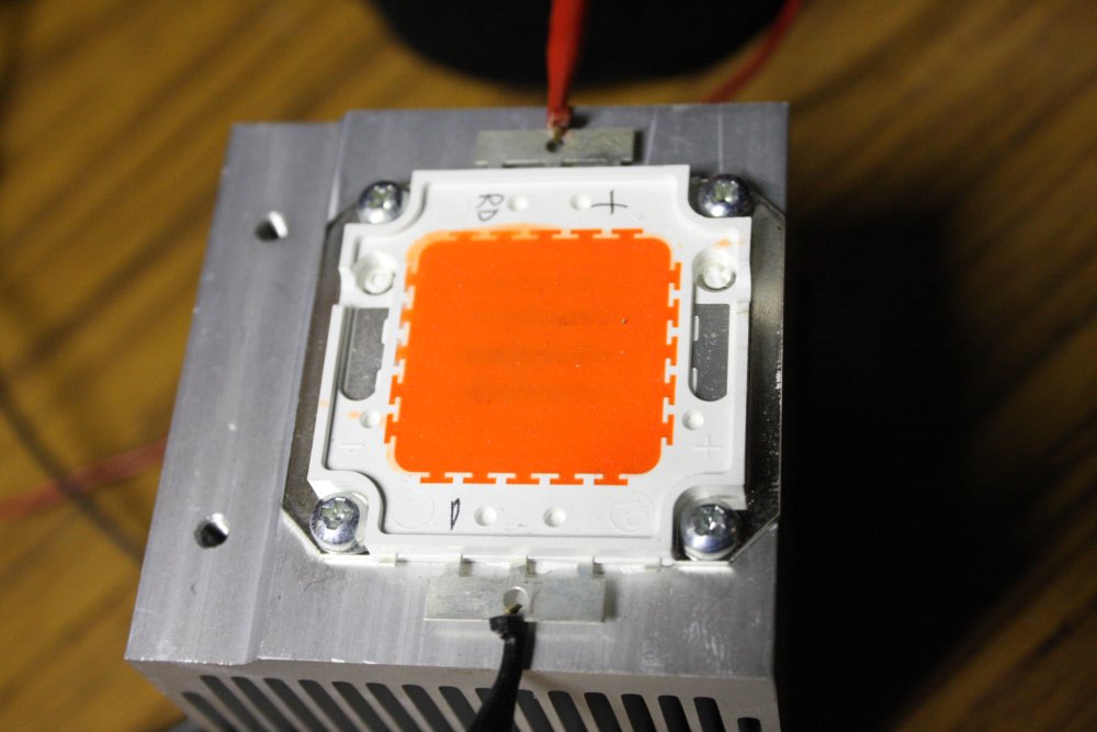
Note the pencilled on "+" signs. There are molded "+" marks, but very misleadingly they are nearest the negative terminal. The actual LED string bonding terminals are at the left and right in this pic, and the leadframe then wraps around in an anti-clockwise direction to the external tabs. You can check with a multimeter since the leadframe is exposed in pits in the plastic molding.
I knew the 'white' (making double fingered quotes sign in air) is achieved by a phosphor coating over blue LEDs. This absorbs some blue photons and emits in a broad band centered on yellow, giving a spectra somewhat like this:
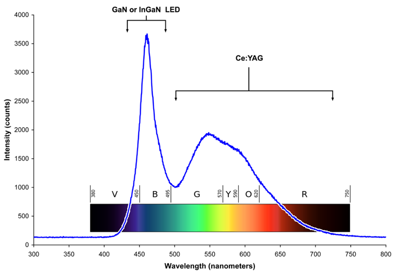
But that's a generic plot, from Wiki. The ebay sellers of LEDs like these never bother with trivia like datasheets giving measured spectra of their components. So who knows what these LEDs are actually producing? I will find out when I get my spectrophotometer going.
Also in the meantime I've ordered a small jeweler's spectrometer. These are cool. Back in high school I got to use one, but never saw another ever since. I hope the US$27 one from ebay seller 'discount_instrument' of Hong Kong works as well. Fingers crossed.
What I'm most curious to find out, is why the red and green 50W LEDs have red and green translucent filler over the LED chips, as opposed to clear filler like the blue one (third from left.) That filler and the wording of the listing makes me think they probably all use the same blue LED chips, with a similar re-emitting phosphor trick used to get red and green. Which means their spectra could be anything at all, and very unlikely to be similar to actual red and green LEDs.
I'll have to be patient, since these things absolutely can't be powered up for more than an instant without a heatsink, as they'd overheat and burn out within a second or two. 50 Watts is a lot of power, and the LEDs have a low thermal mass.
It's interesting that with 10W LEDs in similar but smaller flat packages, the various non-white colours available all use LED chips that produce those colours directly. Why don't the larger 50W ones? I don't know, and I can see it might be a problem.
 |
 |
 |
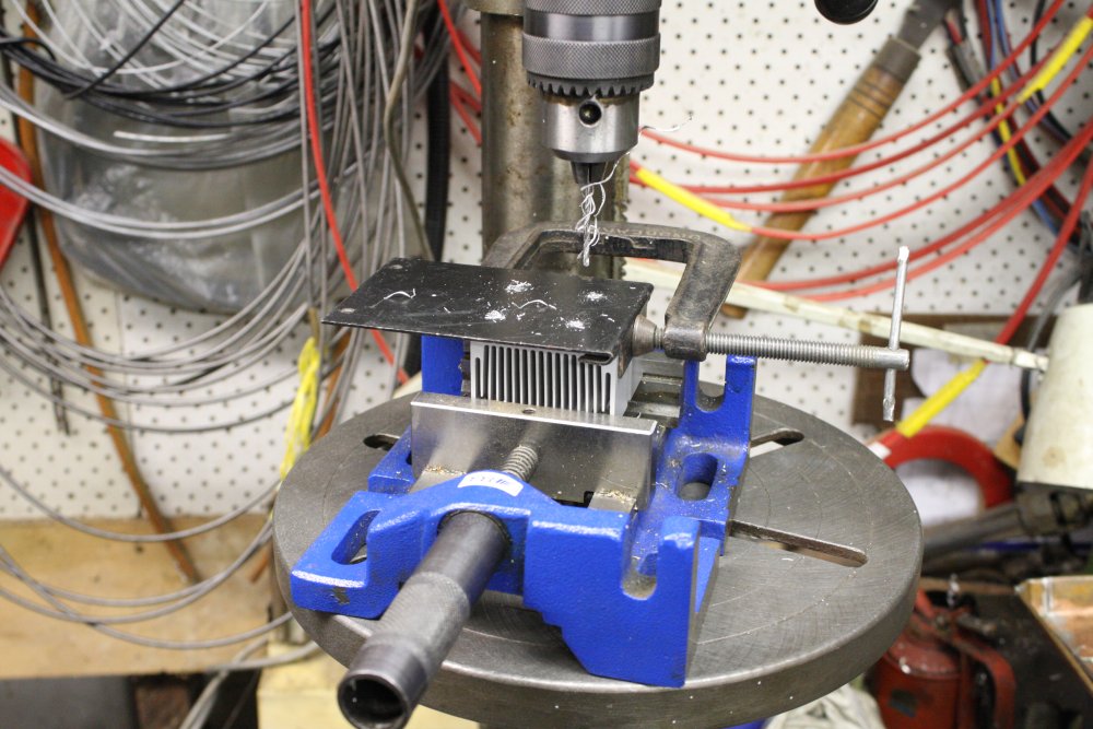 |
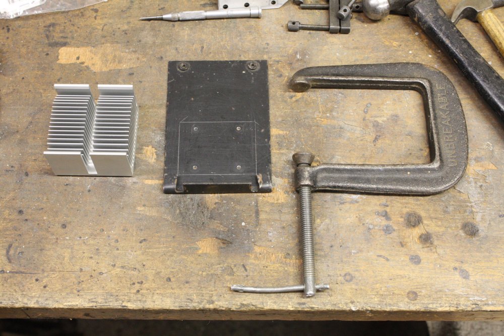
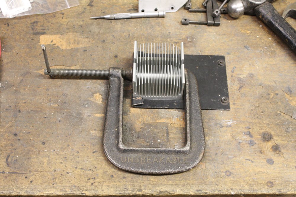
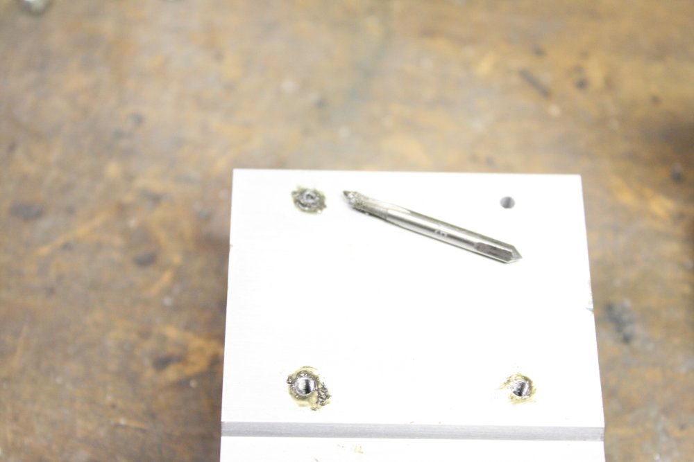
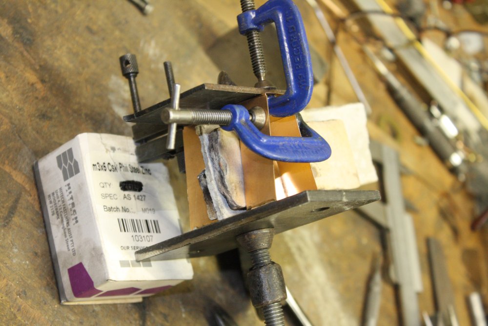
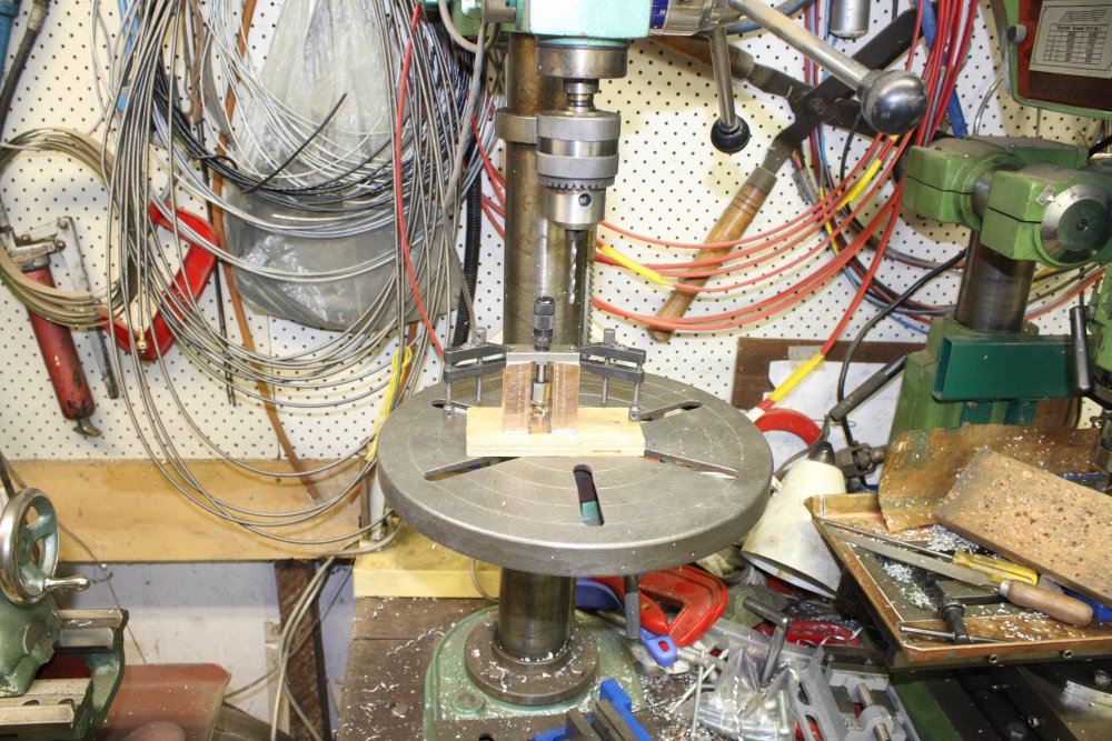
Well, I have four heatsinks to put identical threaded holes in, and I may want to do more in future. So a drill template is called for. I found a bit of scrap steel that could easily be repeatably positioned on the heatsinks, marked and drilled it. Note the drill holes must be the size of the tapping drill, not the clearance drill for the screws. Here I'll be using M3 screws, so the drill is 2.5mm.
 |
 |
 |
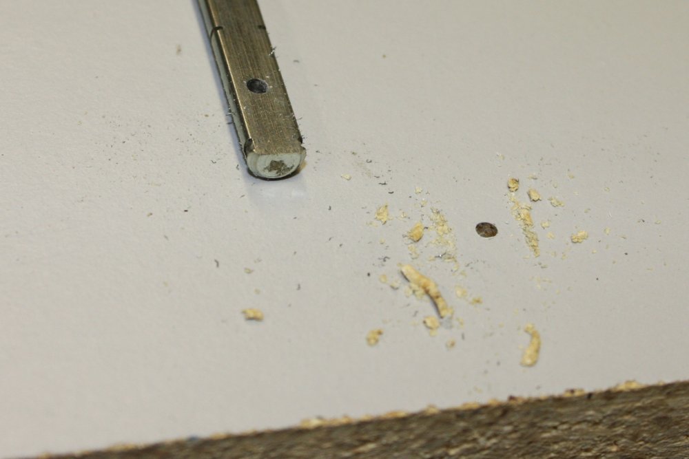
Annnnd... while tapping the 4th hole on the first heatsink, I broke a tap. Bugger. This is a very rare goof for me, and I'm annoyed with myself. The cause is that the holes are not quite aligned with the gaps between fins on the other side of the heatsink. I knew that can risk breaking taps, since it puts sideways force on the tip of the tap as it emerges. I thought I'd be able to feel if it was getting risky. Apparently not. It felt fine, then suddenly, 'snap'.
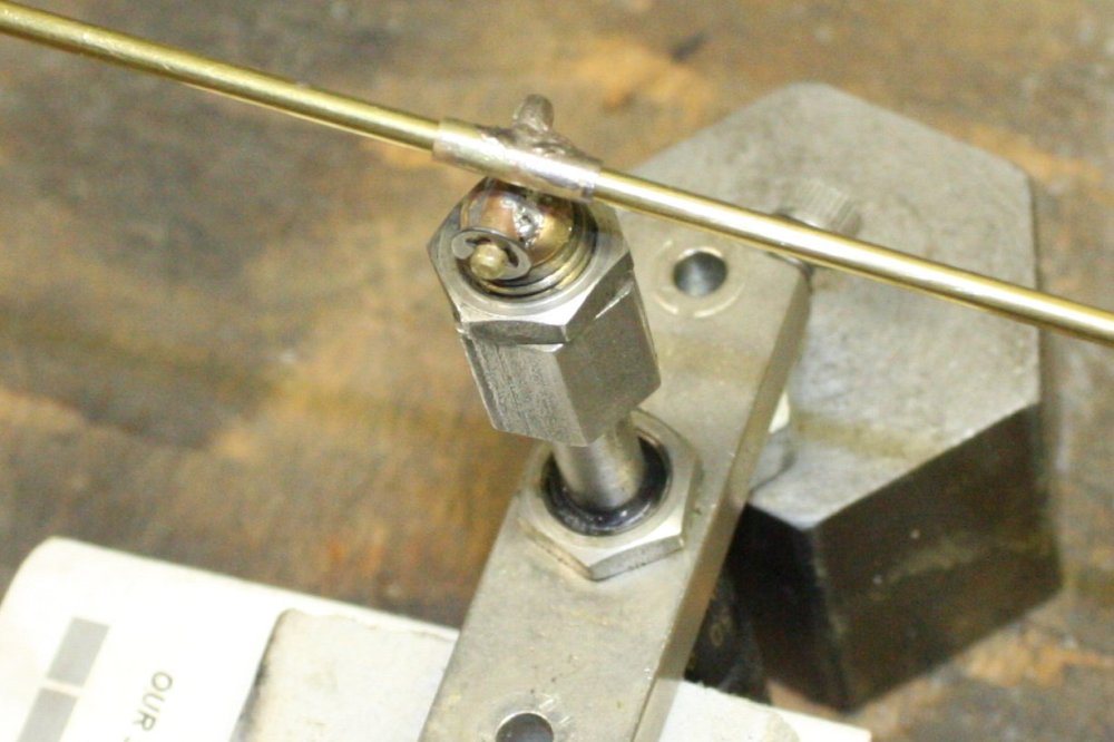
Worse, the tip sheared off obliquely, thus jamming the remainder of the tap, preventing it from being backed out. I ended up deliberately snapping it off again (first pic), leaving two pieces in the hole. So that one is a write off, at least for this project.
For the remainder I used an intermediate tap (shorter leading taper), and didn't run the tip far into the gaps between fins. They all went smoothly.
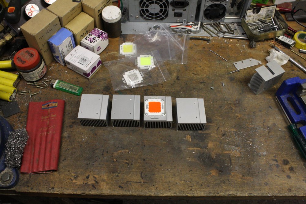
So here they are, ready to power up.
My initial idea for this light, is to have four (or six) of these modules, with all their outputs light-piped to converge at a single small apperture, using that same 'silvery foil glued inside metal shapes' technique.
One problem I'm still working on, is that there really needs to be a parabolic reflector adjacent to the LEDs, to get as much as possible of the light output going along the light pipe. As opposed to bouncing back and forth perpendicularly to the pipe axis, as would happen with some of the light into a directly attached light pipe end. Initial ebay searches for something suitable are looking hopeful.
The better I can get the light entry to the tapered light pipe, the greater the angle at which the pipe can be tapered down to the small end.
 |
 |
 |
Unfortunately my workhorse dual power supply only goes up to 30V, which is too low for these. The ebay listing says "Operating: DC32-36V 1750mA" for all of them, which is another strong indicator they all use the same LED chips.
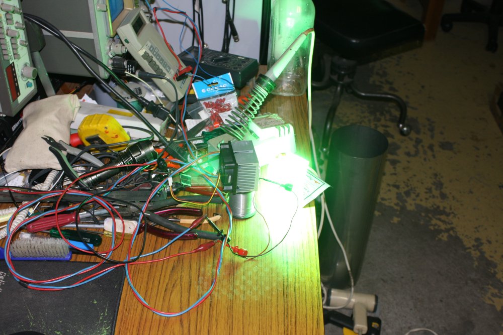
So unless I set up more power supplies on my limited space workbench, with the single output HP 6002A I can only light one of them at a time. I tried the green first, since one idea is to run only a white plus green LED together, using green to fill in the gap in the white spectra. And I wanted to know if this data from the listing was for real:
Red         620-625 nm   500-550 lm
Green       520-525 nm   500-550 lm
Blue        450-460 nm   2500-3000 lm
Cool White  6000K-6500K  6000-7000 lm
Could the relatively very low output lumens for red and green be true? I just wanted a rough visual indication.
The green is a calibrated 'eye searingly bright'. My first mistake right after turning it on was to look directly at it for a brief instant, just before I was about to leave to drive at night to pick up a pizza I'd already ordered. Oops. Luckily the street lamps are quite bright, because I was driving for a while with burned-out vision.
I don't have a light power meter, so improvised a rough emphirical test for comparisons. How close can I comfortably hold a finger tip to the LED face? Even thinking of such a test being workable still makes me laugh, having spent my early life in a world without LEDs, then for a long time only pathetically weak ones that you couldn't feel any heat from at all. Now there are cheap LEDs you can't even hold your finger near without getting burnt.
For the green, running on 1600mA, 'finger ouch distance' is about 1cm from the LED face.
It's interesting how much more sensitive eyes are to green than blue. On the same drive power, the green looks much brighter than the blue (going by reflection off white paper, not directly looking at it.) Yet the fingertip test says the blue is outputting easily twice the radiant energy. Finger ouch distance for the blue is about 2cm — twice that of the green.
I can't tell from looking at these whether the LEDs are blue under the phosphor, since it's opaque enough to block all blue light. As you'd expect. But if they are blue LEDs, that output power difference says the blue-to-green conversion is not very efficient. Which means the phosphor material is taking a thermal beating, and I wonder how long it really lasts?
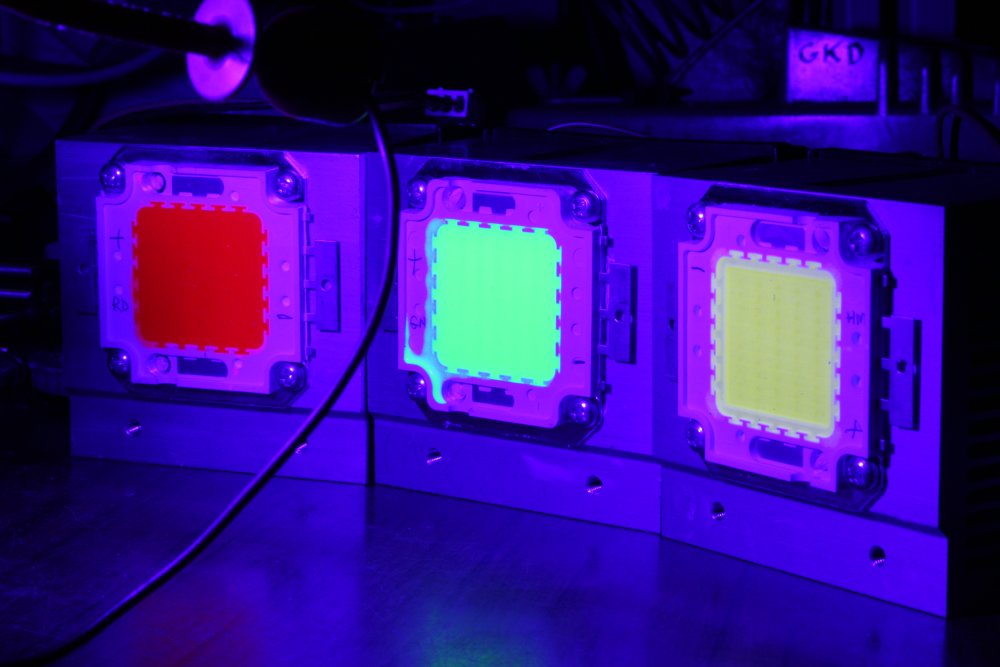
Just to see if the filler material on the red and green really was converting blue to red/green, I put them under the blue LED's illumination. Wow! They light up very brightly. The camera shots don't do it justice; to the eye it looks very colourful and bright. It also makes small spots and overflows of the material really stand out.
 |
 |
 |
 |
Which brings me to the red one. Absorbing blue and emitting red? Why does this give me an 'oh sure' feeling?
Well, it does work. Except at that same 1600mA (less than the 1750mA stated in the listing) the 'finger ouch distance' is zero. Or rather non-existant since I can put my finger directly adjacent the surface and hold it there. The light output is much lower than even the green. So most of the blue photons are dumping into the filler material and wasted. Bearing in mind that blue photons are at the high energy end and red is the low energy end, if this material was working efficiently there should be more red photons coming out than blue going in. Instead there is just a lot of heat being generated in the phosphor.
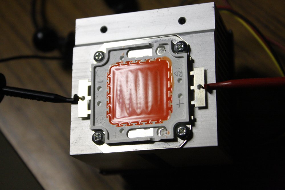
I had left the red one on for a couple of minutes. The fan was having no trouble keeping the heatsink at nearly room temp, so it was barely warm to the touch. There's a generous amount of silicon heatsink compound between the LED back and the heatsink, the LED base plate was about room temp too. Then I noticed... the LED front face was smoking!
I turned it off and had a look. There's now a slight darkening of the filler material over each LED chip, and the surface shows dips over the chips. The surface was smooth before I ran it. So, whatever the material is, it's degrading (darkening and shrinking) rapidly where the blue photon flux is highest. Darkening makes it absorb more photons uselessly, so it gets even hotter. It's apparently entered a failure death spiral, and likely won't last long now.
There's also the factor that who knows what compounds are in the phosphor.. Could be anything — rare earths elements... and no guarantee the smoke from this material's thermal disintegration is harmless.
Well, then, all the better to document it burning.
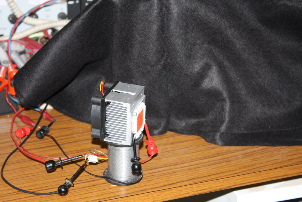
I don't have anything to shoot video, but my camera can do rapid sequence shots. I set up the LED with the camera on a tripod and a black felt background to highlight the smoke, and ran it again.
Here's the result — a 3.6MB animated GIF. Click the image to watch the sucker burn.
The smoke is highly visible since it's so brightly illuminated. It blows around rapidly due to the heatsink fan running.
Remember, this is running at 1600mA, less than the 1750mA maximum stated in the ebay listing. And the LED was never run at more than 1750mA.
I ordered another one, to try at lower power and try to work out a safe operating power. After all they are only AU$4.
Meanwhile I've been considering alternatives to these 'not genuine coloured LEDs' things. Till I see the actual emission spectra I should assume they may not be suitable for what I want to do. Plus there's operating lifespan. Clearly not long for the red, so what is it for the green?
 What alternatives are there?
Well for one thing, the 10W form factor type do have real coloured LEDs available. They can be arranged like this, four to a heatsink.
  Cool white  20000K       $1.87
  Red         660nm        $6.99
  Red         620-625 nm   $4.99
  Green       520-525 nm   $4.99
  Royal blue  452-455 nm   $1.70
  Violet      400-410 nm   $8.99
  UV          395-400 nm   $7.20
I've ordered some of those. Two each except for Violet and UV, 1 ea.
Combining the 50W and quads of 10W LEDs will give me a lot of flexibility. Perhaps one 50W white, and two more heatsinks with a mix of 10W red, green, violet and UV? This allows balancing the number of 10W LEDs as required to even up the spectrum from the large white LED.
I think it will be easier with three heatsinks rather than four. With four I'd planned a 2 x 2 grouping, and that leads to problems with the fan airflow. But with three in an in-line arrangement the airflow is easy, while it should still allow workable light piping.
Update 20150811
The assortment of colour 10W LEDs had arrived, and also the replacement 50W red. In addition I'd ordered some semi-parabolic reflectors and lenses to play with, for both the 10W and 50W LEDs.Meanwhile, giving more thought to the geometry of the 'tapered light pipes', I had a Doh! realization. When I did the illuminator for the Olympus BH microscope I'd carelessly assumed that all the light going in one end of the tapered refective cavity would come out the other end, with only small reflection losses.
However on consideration that's not true at all!
It becomes obvious the instant you actually think about it, as opposed to blindly assuming stuff.
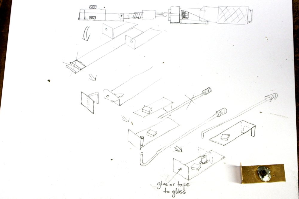
 In this case it occured to me while ebay trawling for 'LED reflectors'. Thinking about ray tracing from the LED through the optics, a light bulb flickered on dimly over my head. Did a quick doodle (at right) to check brain cells are not having geometric hallucinations.
Oops... With every reflection inside the reflective cone, any given ray becomes more tilted back towards the big end of the cone. Which means for some angles of entry, the ray 'comes to a halt' before reaching the smaller end, then reverses direction. Considering that I knew perfectly well about corner cube reflectors, and that the tapered cone reflector is an intermediate case between a corner cube (100% return reflection) and a parallel-walled light pipe (100% transmission), it should have been obvious from the start that boundary conditions needed to be checked. Feeling so stupid...
The more I thought about it, the clearer it gets that this is quite an interesting and complex problem.
The objective is simple: an optical system that captures as much as possible of the light emitted from one (or more) high power LEDs, and ends up with that light emerging from a small (a few millimeters in diameter) aperture with uniform, homogenized radial distribution within an emission cone optimized for coupling to a microscope's lighting path. Effectively trying to emulate the light output from a small filament in a bulb, but with all the light emission magically constrained to a cone on one side (for minimal wasted light.)
In practice, there are several complicating factors:
- A starting point would be polar emission diagrams for the 10W and 50W flat LEDs I'm using. There should be data like this:
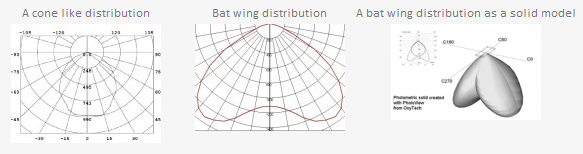 However given the LEDs I'm using are from China via ebay and there's not even any manufacturer part number, the complete absense of such component data isn't so surprising.
It does mean I have a choice — I could either build a setup to measure the polar output distribution and then try to construct a software model of the optics, or... I could do the entire process emphirically. (Ha ha... or both, if I was really a masochist.)
- Each optical element in the chain after the LED will have its own complicated characteristics. Again with probably poorly defined specs (especially for parts I improvise.) In the simple illuminator I made for the Olympus BHM, there was only the LED, then a conical reflector followed by a single frosted film as diffuser. And that was bad enough.
But for this next one, there will be multiple LEDs, resulting in the extra problem of combining their outputs into a homogenous final output. Also it was by now clear that the coupling from the LEDs to whatever I used to concentrate and combine their outputs, would greatly benefit from something directly after the LED, to get most of the light pointed in roughly the right direction.
Hence those parabolic reflector and lens assemblies I'd bought. - There's also the need to avoid ending up with any trace of an image of the source LEDs in the output light. Put another way, the final light output has to be brightness and spectrally homogenous across the field of emission. This eliminates any possibility of using simple lens series alone.
- I can construct simple custom reflective elements (using that glued-on foil technique, which is limited to one plane of curvature), but I can't make or easily/cheaply obtain custom glass lenses. So for lenses I'm limited to what I can find online. Also a requirement in this project is to come up with a design other people can copy or adapt to their own microscopes. Which translates to 'avoid lenses if at all possible, except for ones widely available very cheaply.' Like the ones designed for these LEDs. And bearing in mind those do produce a nicely focussed image of the LED, so other steps have to be taken to overcome that.
Which all boils down to — Emphirical is the go. And so I need an optical setup for experimenting with LEDs, lens and reflector arrangements. Without buying some hideously expensive precision optical table gear. What I need is a 'free and good enough' optical table.
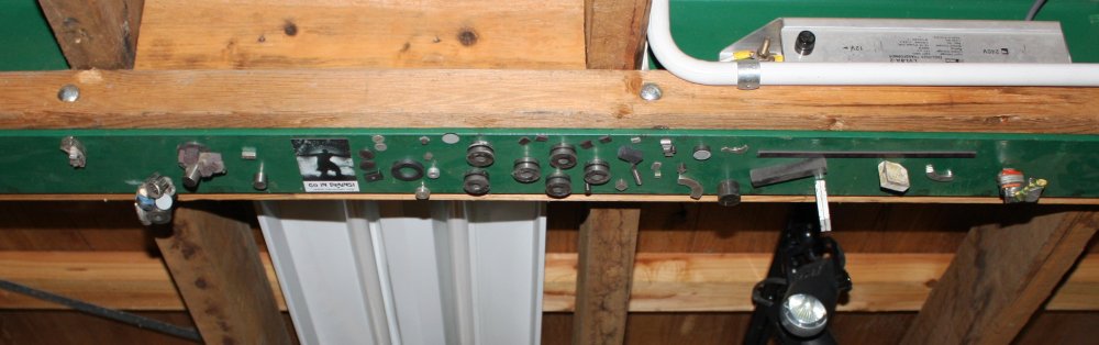
It's times like this, when years of scavenging bits from discarded spacejunk pays off.
 |
 |
 |
Big box of nice front-silvered precision mirrors from photocopiers and laser printers? Check.
Plenty of small but strong magnets from hard disks and CD-ROM drive optical heads? Check.
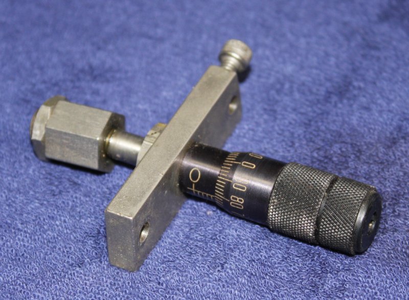
Four vernier positioning adjusters, from some old waveguide tuner? Check.
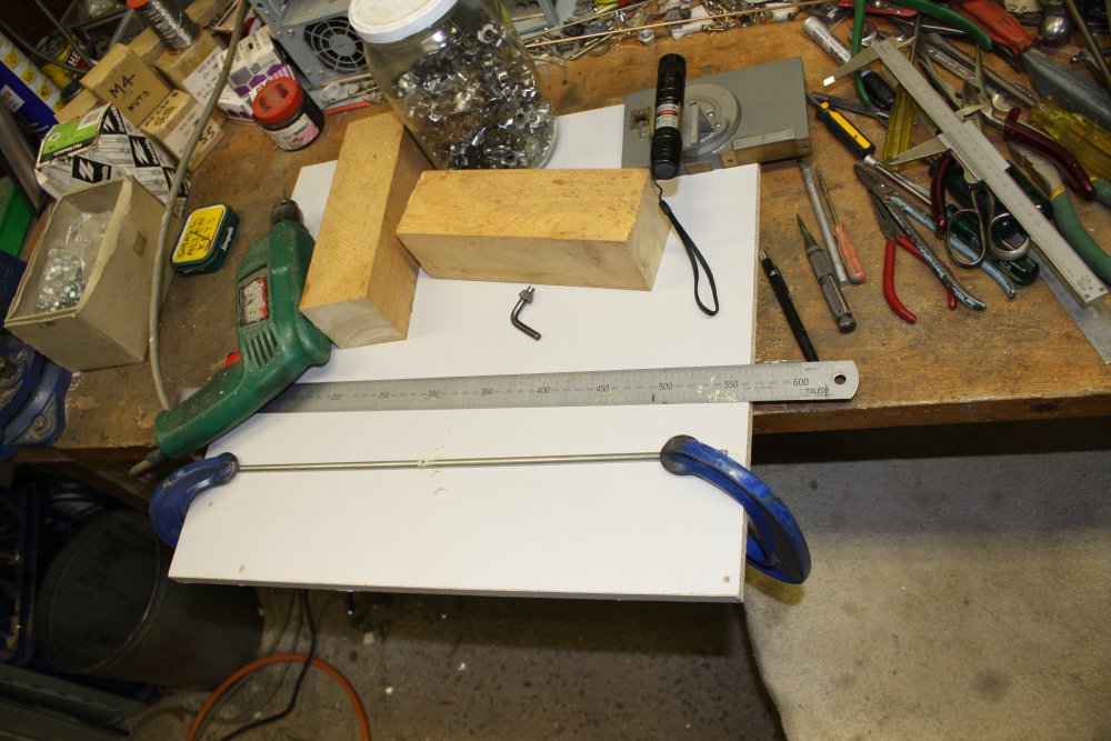
Solid steel base plate, springy non-magnetic sheet metal, solder, stiff wire, laser pointer, etc... Check.
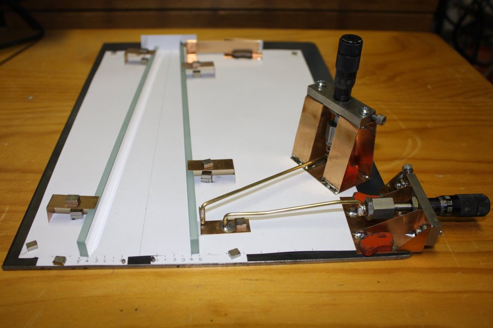
And so on. Here's the 'optical test table' build:
 |
 |
 |
 |
 |
This first row is included only to demonstrate that drawing 'plans' can be relatively useless. Except perhaps as a lesson in how not to do something. That drawing shows five different versions of the evolving idea for the horizontal adjuster. None of which I ended up using, except sort-of that final little bracket at lower right.
#2 & 3 were the first idea of a push rod soldered directly to a screw that fixes to the end of the vernier. Then the solder joint broke as I was bending the rod to adjust the angle, since I didn't drill the mating hole far enough into the screw head.
#4 & 5 are the same thing, this time silver soldered. Which I then scrapped after deciding it was more flexible to have the rod detachable and pivoted at both ends. Also allows easily making different length rods.
Only pic #5 is useful, since that was preparing to solder the support frame for the vernier. That part worked.
 |
 |
 |
 |
 |
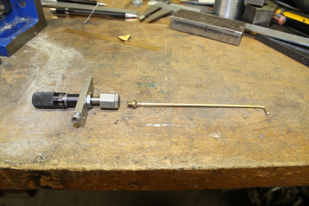
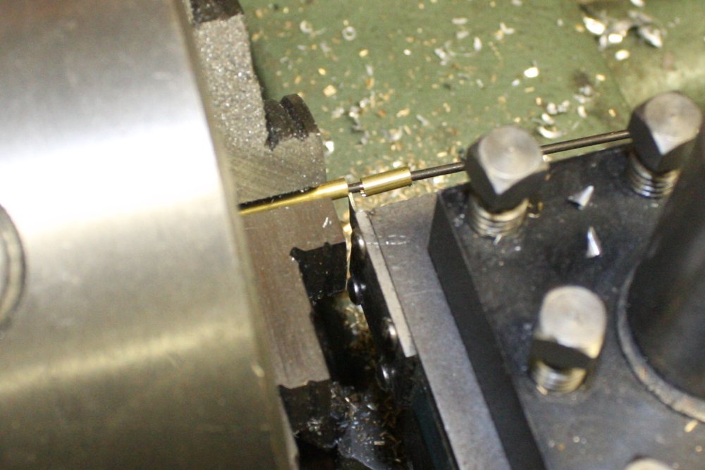
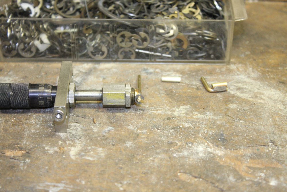
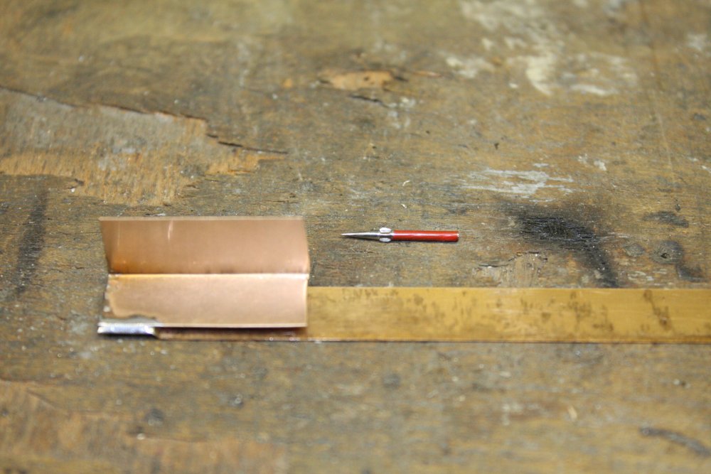
1. I'd been lucky, that I had some fine brass precision tubing with a very close fit to my stock 2.4mm bronze rods. To get a neat cut on the fine tubing, I used this mini parting tool I'd made. It's a holder for a piece of hack saw blade, ground to the appropriate cutting point.
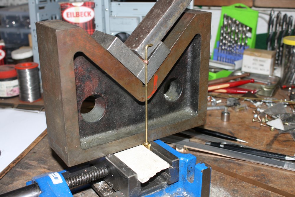
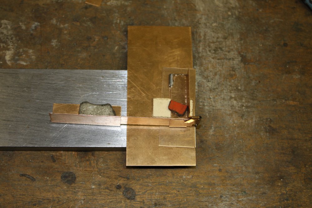
2. For the vertical vernier (mirror tilt adjustment) there needed to be a universal & sliding joint at the vernier. This is starting take 2. The first attempt is at the right, but wasn't adequate due to sideways looseness in the vernier end attachment.
The tiny surface slot in the brass rod for the circlip, was made with the same tool used to cut the tube.
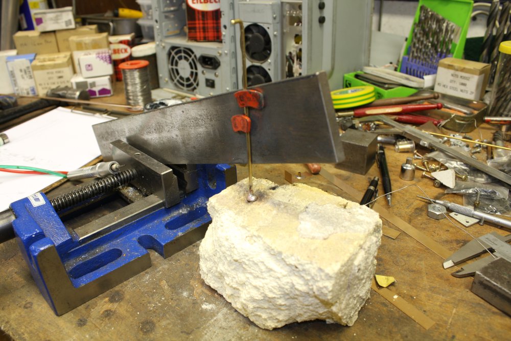
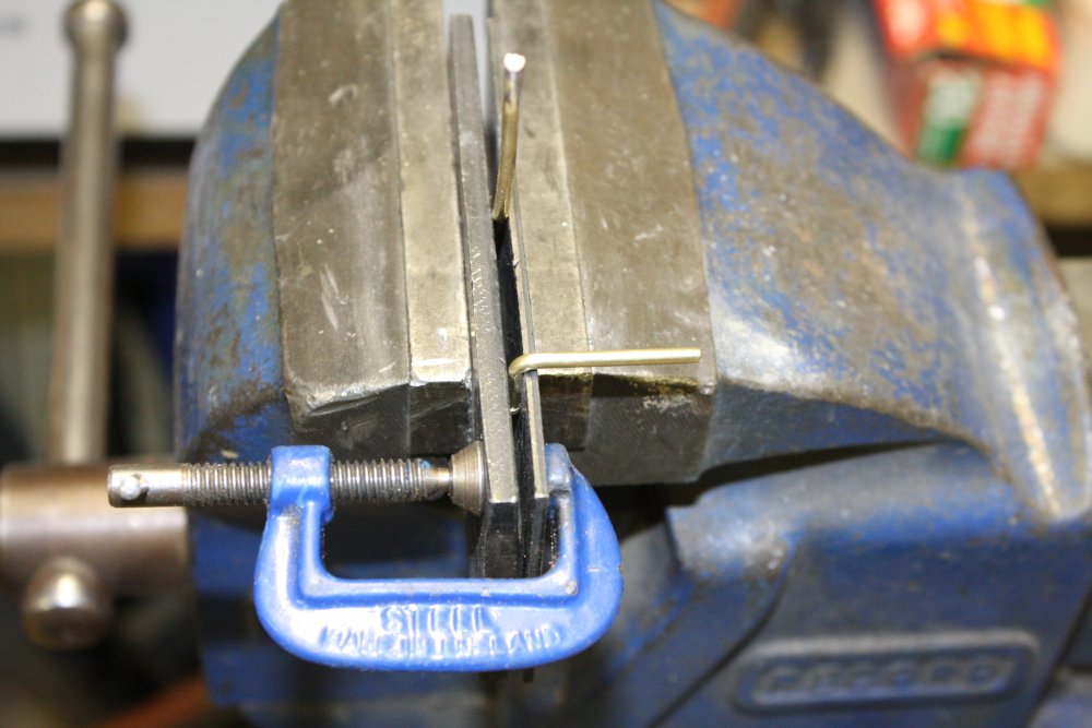
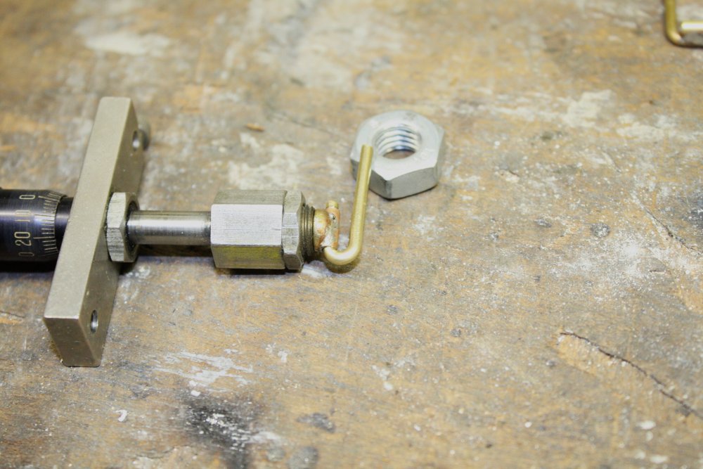
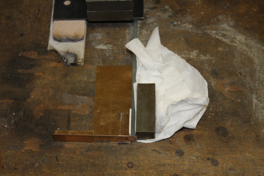
3. Starting a tight U-bend for the universal joint.
4. That bend.
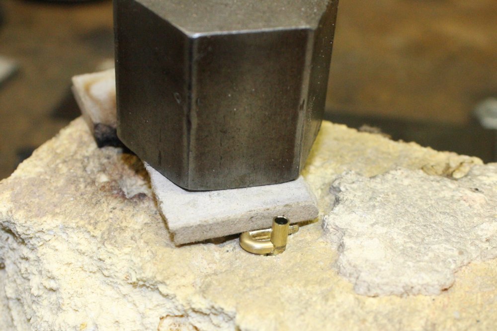
5. Preparing to silver solder the sliding sleeve. For tiny joints like this, the technique is to cut a little sliver of silver solder from the rod (about the size of a pin head), stick it to the joint with the wet paste of flux, then while heating it all with the miniature torch, use a fine stainless steel pointy pick to push the molten blob of solder into the right place to wet the joint.
The thing the brass pieces are resting on, is a piece of light insulating firebrick. It's a soft crumbly foam, easy to make holes in (as for holding that bit of tube upright), and can be shaved to finely adjust the position of the other piece.
 |
 |
 |
 |
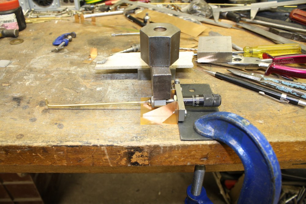
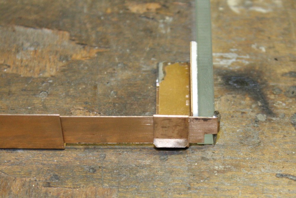
1. The finished universal joint. The aim is to adjust the height of the rod, axially to the vernier, while allowing all other degrees of freedom of movement.
2, 3 & 4. Making the stand for the vertical vernier.
 |
 |
 |
 |
1. Starting on the pin pivot point mounting for the other end of the mirror. You'll see how it works later. The red thing is an old gramophone needle, which are made of very good steel. After removing the red paint it can be soldered, which isn't hot enough to spoil the temper of the steel.
2. The pivot has two parts, one to attach to the mirror, the other to provide down-pressure on the pin point. Here I was just about to solder them together, when it occured to me that they were better left only loosely attached, by a spring clip.
3. Pressing the double sided sticky tape to the mirror back. The tissue is to avoid scratching the silvering on the mirror front.
4. Done. Except the pin will be slid back further in use on the table.
 |
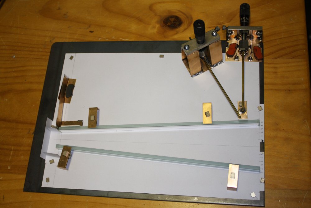 |
This part of the setup finished. Everything is held down with magnets. The mirrors lightly using those L-clips and small magnets with some air gap between them. (Those ones are from CD-ROM optical heads.)
The verniers are held down with pairs of hard disk head-servo magnets on each side. These are really solid; it takes quite an effort to shift them. The phosphor-bronze sheet is thin (0.3mm), stiff and non-magnetic, so the hold-down frames are very effective.
If I want, I can arrange this as a scale model of the tapered reflector in the Olympus BHM microscope. It isn't at present.
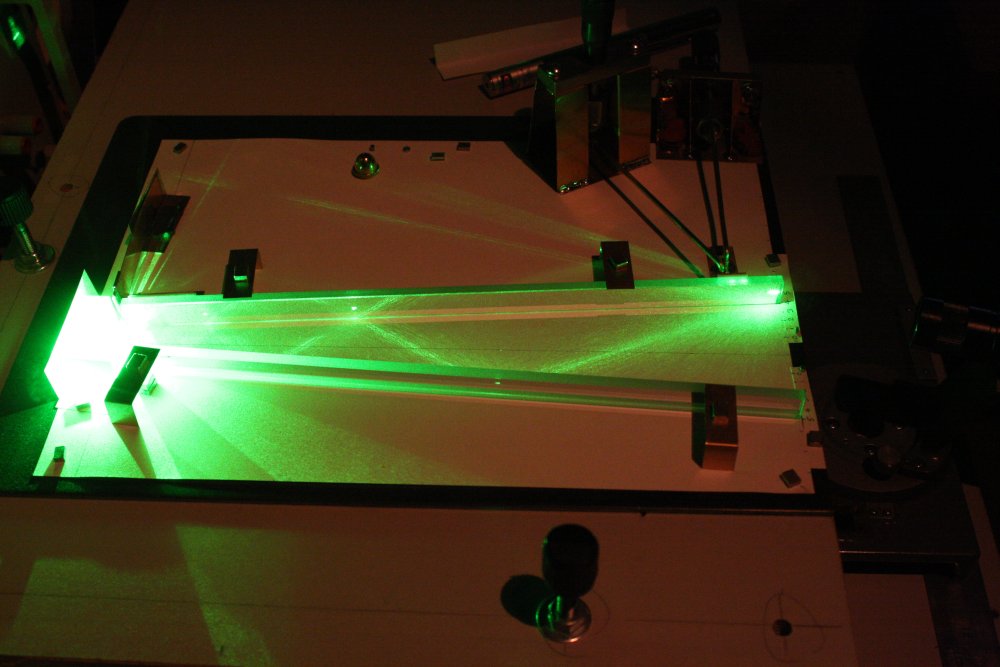
Yes, I'd already played with it with the laser much earlier in the process, but I'm saving the pretty light-path photos for later. Here the horizontal position adjuster isn't all that useful, since meaningful adjustments are coarse enough to do by hand, simply sliding the mirror to positions according to marked graduations on the base paper. But the vertical adjustment is very useful, and you'll see why in the laser ray trace pics soon.
First though, there's a bit more construction needed.
Update 20150814
The laser height, angle and offset relative to the mirrors needs to be adjustable. I had a bit of old junk that would do for the angle pivot, it could be mounted on a slide for the offset, but the height is fixed. So for that the entire table (built so far) will have to be height adjustable relative to the laser.
 |
 |
 |
 |
 |
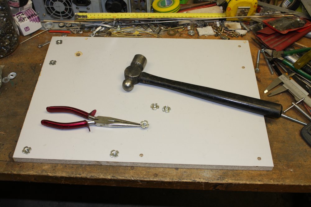
1. After cutting couple of pieces of scrap chipboard to size, hammering in these threaded things (don't know what they are called) into the bottom at points where I might want to place the adjusting screws for various different configurations. These are more 'junk I found somewhere'. So still in zero cost land.
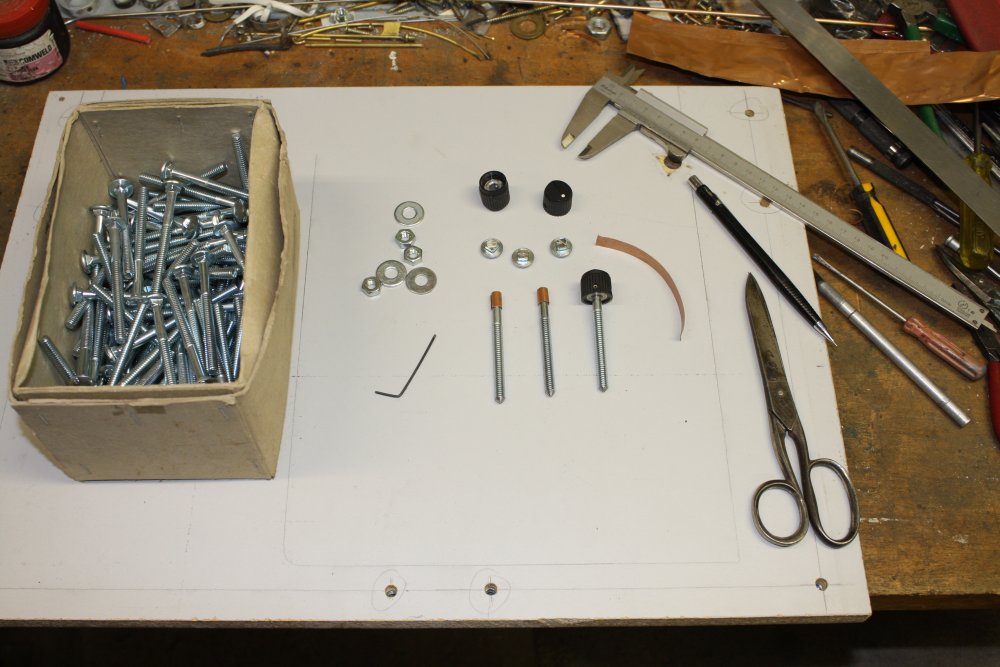
2. Three 1/4" x 3" coach head bolts being converted to height adjusters. Ground the ends to a point, cut the head off, replace with knobs. Needed to shim the diameter up with some copper foil, since the "1/4 inch" bolt's shanks are less than 1/4" diameter.
3 & 4. For the slide, in my box of rods from old printers I found one with a flat face along the side, and about the right length. Drilled three holes for mounting screws, and here I'm drilling through those into the chipboard. The holes are M2.5, to be tapped for M3 screws. The chipboard holes will get re-drilled to M3.
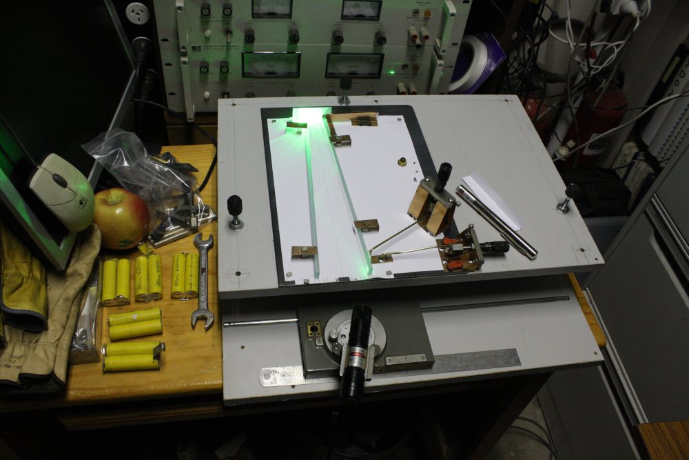
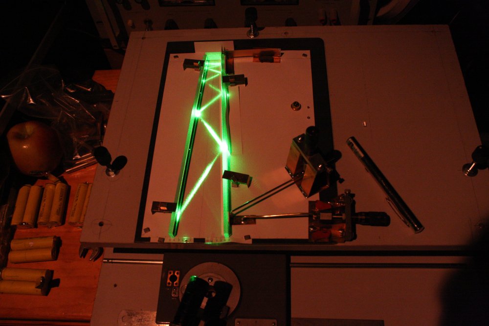
5. Pretty much done. Only slight problem is that with everything properly adjusted so the beam reflections are down the centers of the mirrors, you can't easily see the beam pattern. Blowing some dust in works, but I can't do that for photos. I have a small cylindrical lens, that fans the beam in one dimension allowing it to show up on the paper all the way through multiple reflections. But this requires a way to precisely position it in front of the laser. Hmmm...
 |
 |
 |
 |
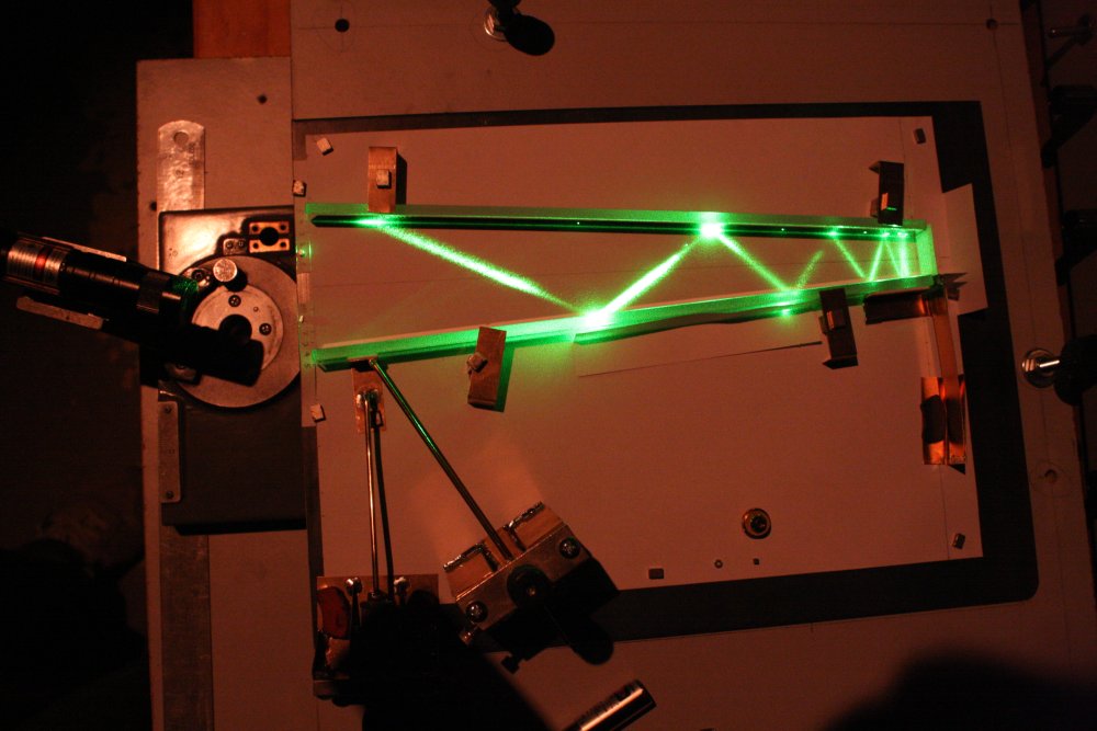 |
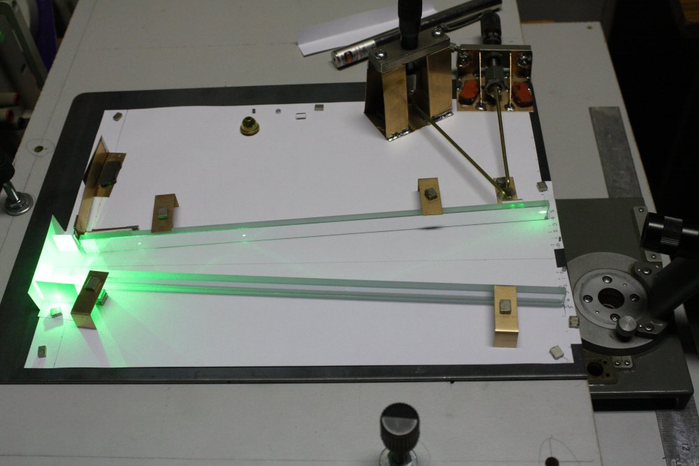
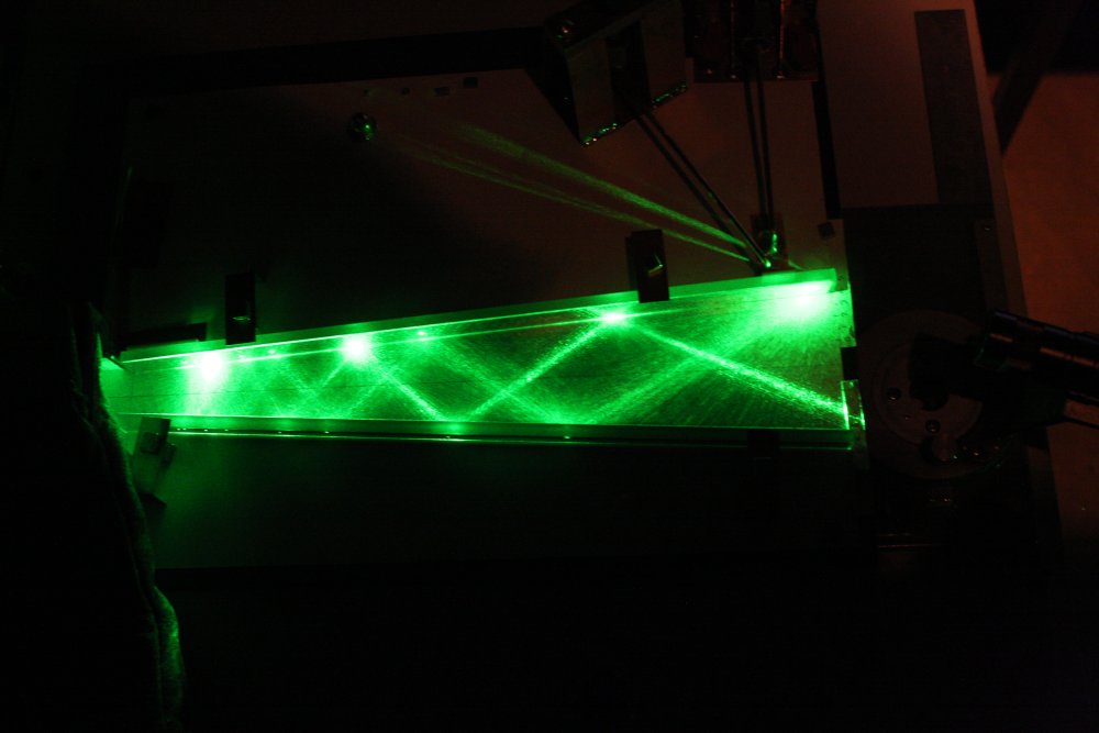
Playing around with it. Even without the cylindrical lens, #5 happens to give a good idea of the 'never made it to the end' geometry. In this shot you can't see the entering beam (except as dots on the upper mirror.) But a chance bit of dust on a mirror in the area where the beam approaches the limit of how far it gets into the V, has spread the beam so there is spill onto the white backing paper through all the refelctions on the beam's way back out. Thus illustrating the progressive beam angle change.
Still waiting for the LED reflectors and lenses to arrive.
With those I can try to work out a geometry optimized for maximum light coupling. But I already see even this randomly chosen geometry with no lens is not too bad. For a 1st reflection right at the entry end of the mirror the beam entry angle has to be 18 deg or more off the axis for it to fail to come out the other end.