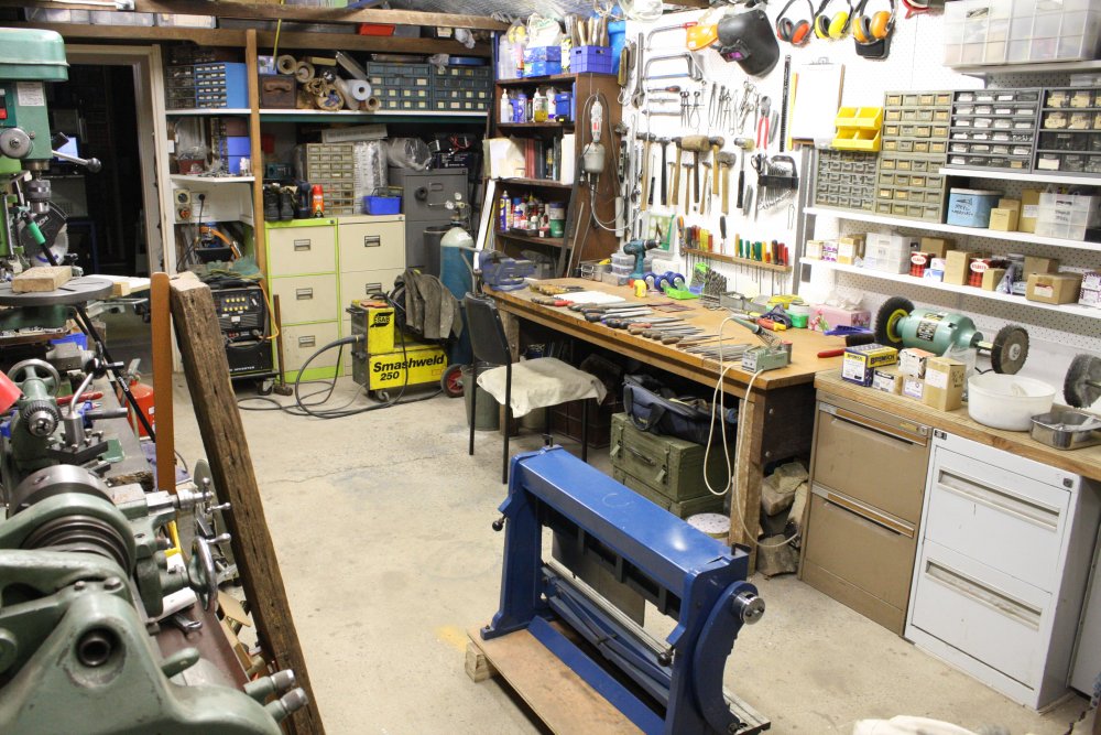
Ah Spring! Time to take on another project. It's not like the other many projects can't wait, right? This one began with the honest intention to just do some Spring Cleaning.
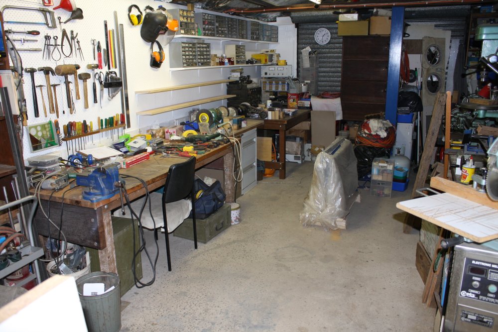
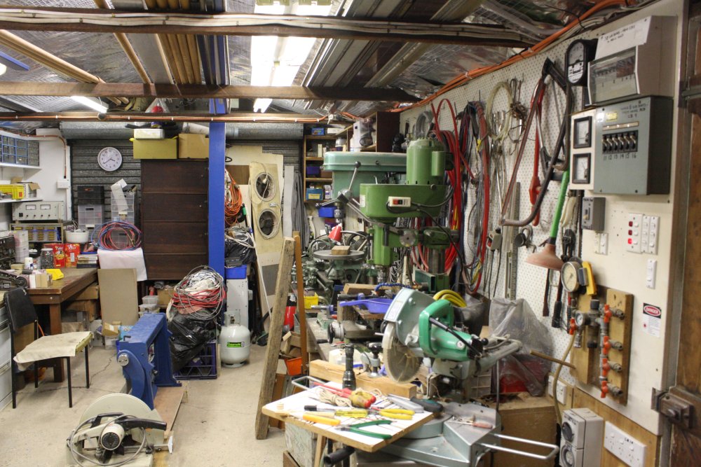
My 'workshop' mainly consists of two interconnected rooms. One is an old fibro single car garage, that was built long ago by the previous owner — probably during or just after WWII if the complete absense of reinforcing steel in the concrete floor slab is any clue. When it became mine in 1987 it was very plain; just fibro on a timber frame with no lining of either walls or roof. The floor slab was already cracked. It had no electricity or water. In summer it was unbearably hot. The eaves were open, so unavoidably there were resident possums with their chewing of everything, possum pee (most corrosive liquid short of hydrofluoric acid), and any number of funnel web spiders.
And yet, we (my then wife and I) owned the place. At age 32 this was the first time in my life I'd had anything at all that could realistically serve as a dedicated workshop. It was heaven.
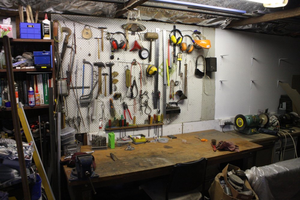
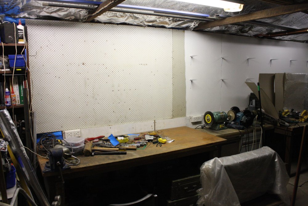
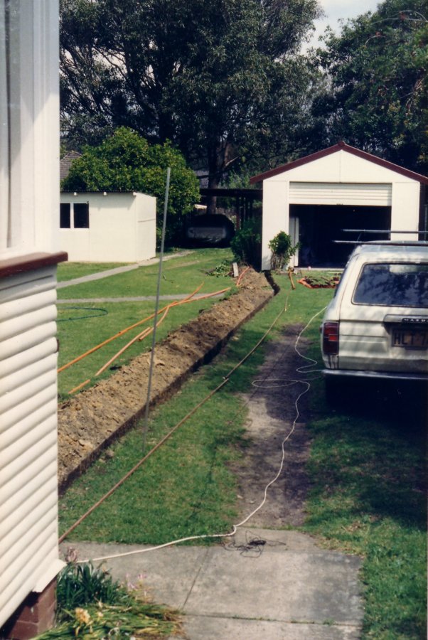 Here it is, in all its newly bought 1987 glory. In those years money was tight for us, since we wanted to pay off the mortgage asap. So I tended to be very frugal with taking film photos. This is the only photo I can find of the old garage from those years.
My first task was to bring power and water to it. Which is the trench seen here.
Over subsequent years a lot of building work went on around the old fibro garage, but the garage itself stayed much the same. Apart from a few crucial improvements like permanently evicting the possums. It's not easy to reorganise a basic workshop, when it's in constant demand supporting other efforts. One of which was personally building a much larger '4-car, 2-storey garage' behind the old fibro thing. (Yes, it's a large block of land.)
That went up in 1998-9, with the initial purpose of something to live in while the small old weatherboard house at the front was demolished and replaced with a large 2-storey house, in 2000. After which the 4-car garage became my 'bigger workshop', intended ultimately to be an electronics lab.
Ha ha... 'ultimately'. In practice it was a storage shed for a random mix of building materials, woodworking area and my growing collection of antique test equipment. I'd discovered ebay and the feasibility of buying from the USA, which mean that for the first time in my career as an electronics engineer I could actually buy nice gear for myself. Where 'nice' meant the kinds of things that were cutting edge back in my early years when I'd so wanted them but had zero chance of affording. I still couldn't afford 'new things' now, but I could buy some long-held dreams...
The new building also acted as storage for a few actually useful largish things. Mind you there was no organized storage shelving yet, so the whole place was 'piles of stuff'. Often covered in fine wood dust, from saws, router, power plane, etc. Dust cover sheets are futile when faced with router dust. Probably even Level III hermetic bio-containment with positive pressure wouldn't be enough to keep fine wood dust out of electronics. This 'mixed misuse' arrangement wasn't very workable.
Gradually I've been sorting through the jumble-packed jigsaw puzzle, improving the storage systems, space allocations, and general facilities. First major advance was to make a rule: "No more woodworking in the electronics area!" Another big improvement was to join the two main work spaces via a short passage between the separate buildings. Being able to walk directly between the electronics and mechanical workshops had been planned from the beginning, but took years to get there. The downside is now metal workshop dust (grinding, soot, etc) can get into the electronics. It's hard to remember to close the separating door.
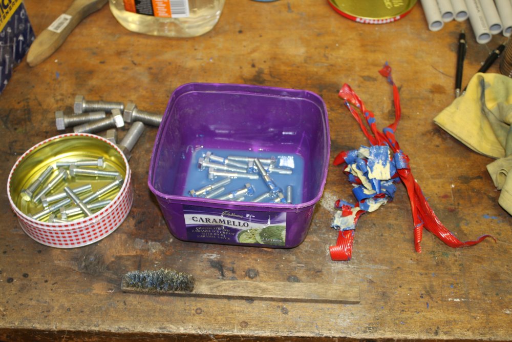
This Spring I decided to finally have a tidy up of the old fibro 'mechanical workshop' shed, and another cycle of sorting stuff out between the two spaces. For instance why is most of my nuts and bolts stock still in the electronics lab? Is stupid...
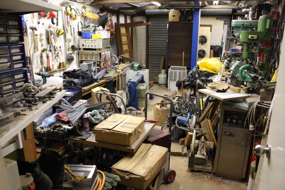
The first part of the plan required dismantling an ever-growing pile of junk storage taking up about a quarter of the fibro shed floor space. This area was so bad I don't even have a photo of it all. The 'look away in disgust and shame' effect I suppose.
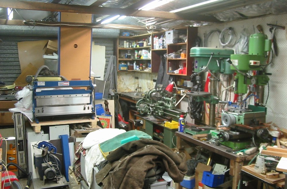
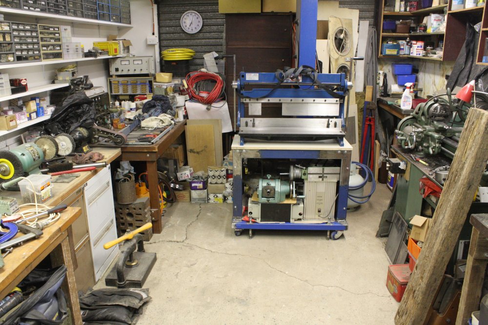
That's the closest view I have. Taken way back in 2012, the mess pile beginnings are at center-rear and off to the left in that photo. It got much worse. Though I did manage to keep the metal folding machine seen there accessible. Most of the time.
 |
 |
 |
 |
 |
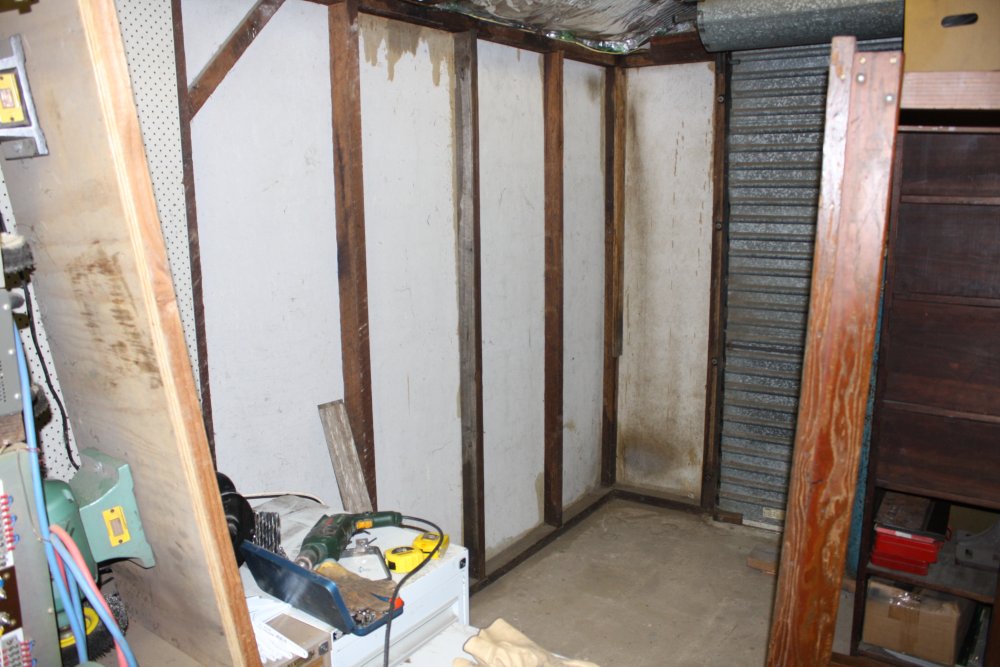
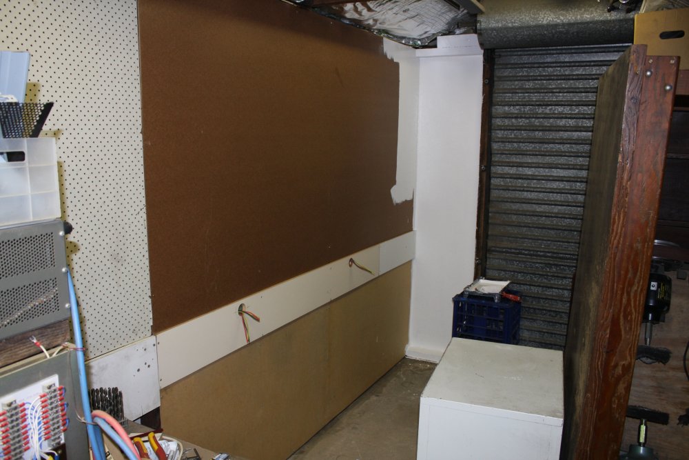
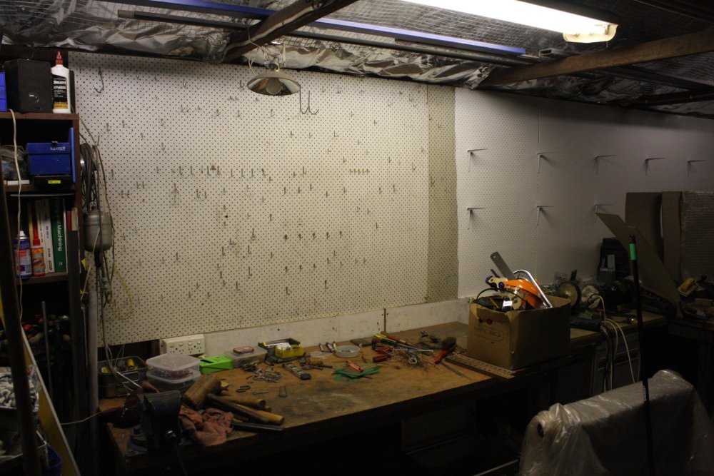
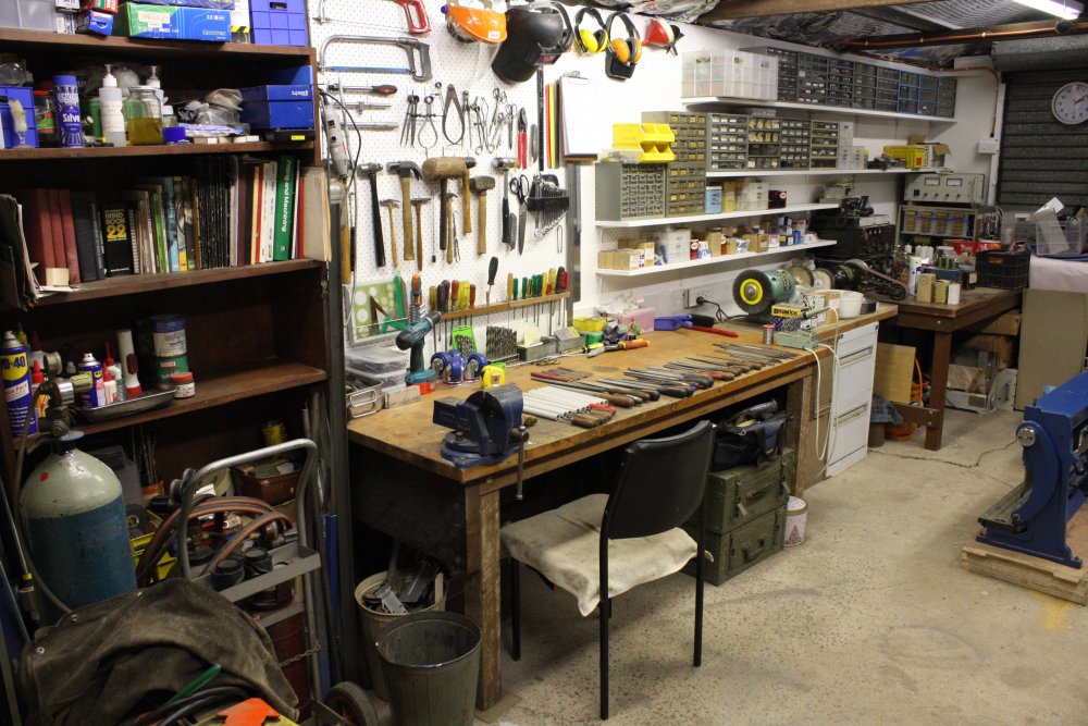
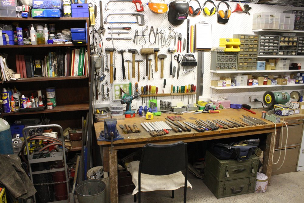
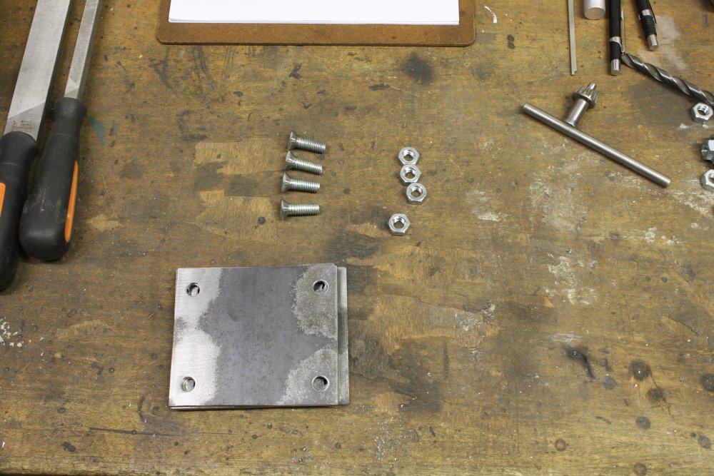
1. The mess pile too terrible to be seen has been removed, and only a few remnants of it clutter the room. The bench leaning up against the wall is one I made in my teens and have used ever since — until 2013 when I disassembled it as part of some electronics lab improvements. I'd stored the bits, but somehow managed to misplace the bolts. When assembling it the search for the bolts became a major distraction. Really annoying to discover I'd done something careless with part of a childhood relic. Why weren't they with the bench parts? I had no idea, and stuff like this makes me suspect I'm getting Alzheimers. Eventually I gave up looking and bought new bolts.
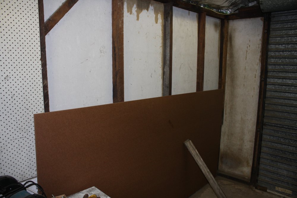
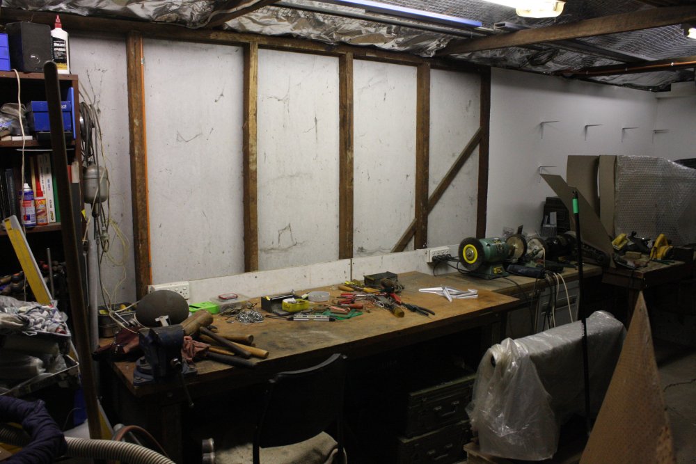
2. Cleared corner space. Most of the brown stains are Creasote, applied after one of the several termite incursions. Notice one of the upright wall studs is different? The original one got eaten. The brown-gray stain at bottom right is where a possum made a nest between a box and the wall. That's the colour of possum fur oil.
3. Sizing up a sheet of masonite to fit. I'm kind of amazed this stuff is still made, since everything else really useful and good tends to stop being available. Like Creosote for instance.
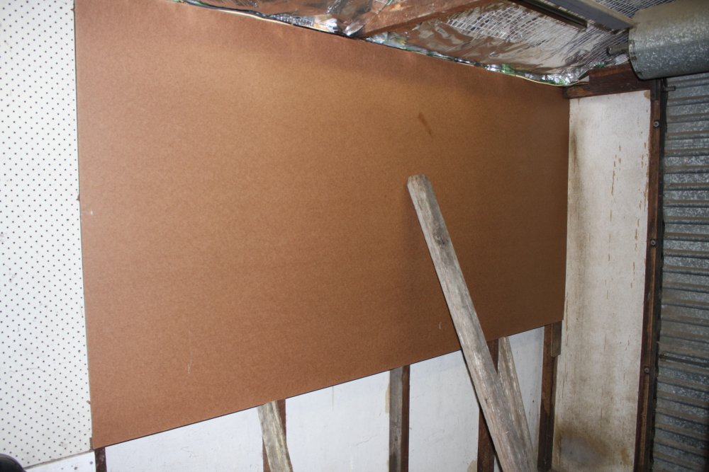
4. The masonite propped in place. But not screwed on yet because...
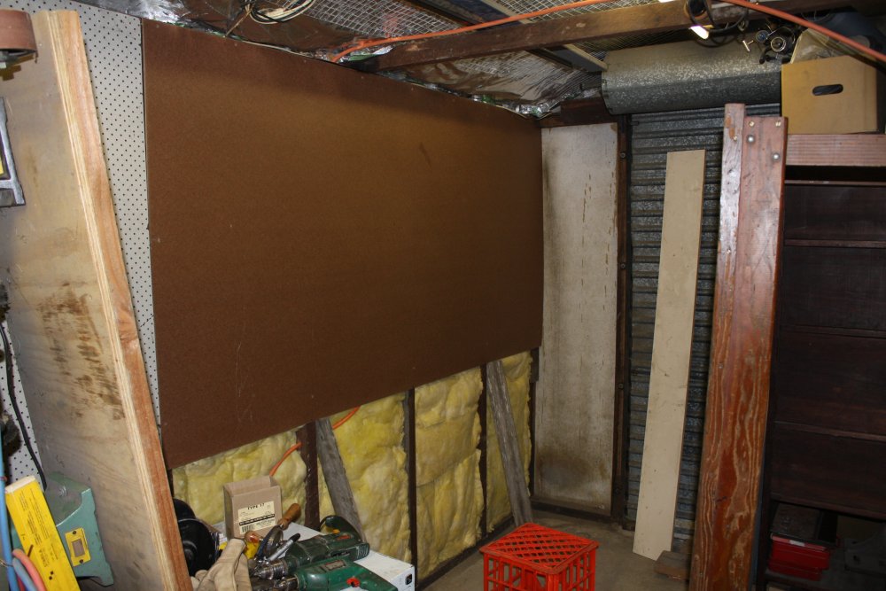
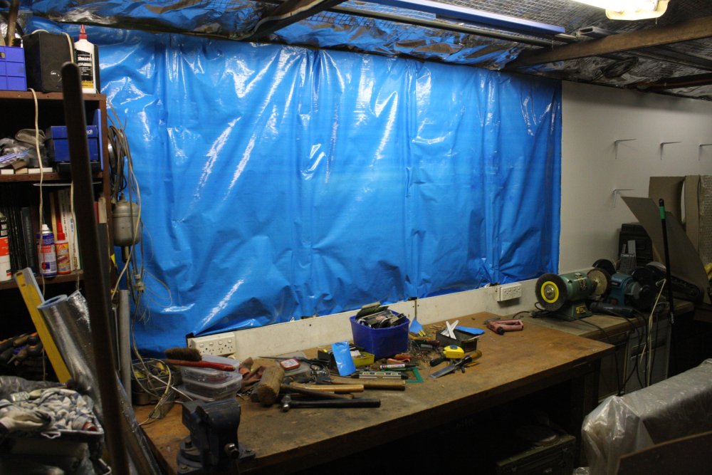
5. I have plenty of glasswool insulation, and it would be silly not to apply some here. The ceiling got insulated already a while ago, and I do bits of the walls as they come accessible. Also there was wiring for extra power points to put in place.
 |
 |
 |
 |
 |
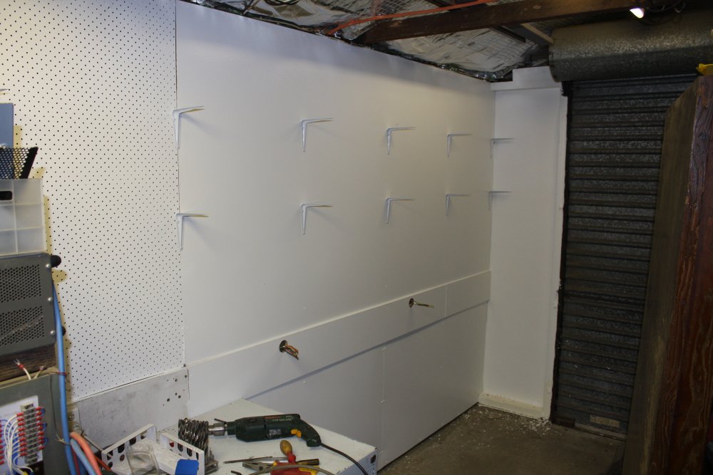
1. Screwed on, hopefully never to be removed. Also a bench back board, for the power points.
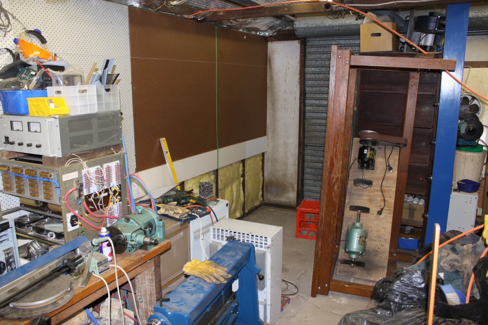
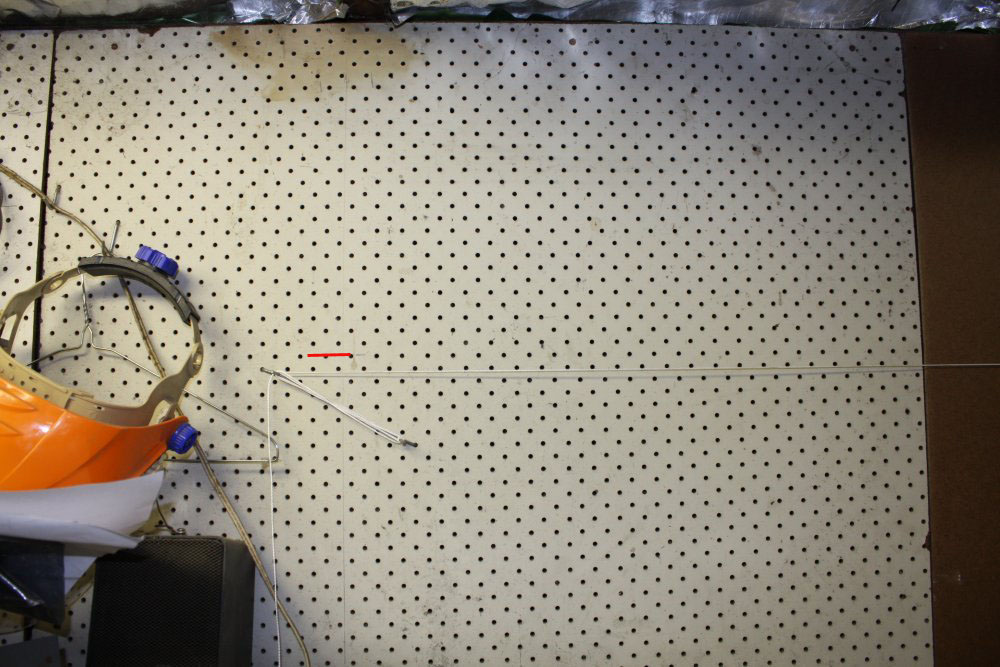
2. String line for the shelves. Now this is annoying. The floor slab is cracked, and there are no other foundations. The whole building is sitting on tree roots, which are playing a slow juggling act with it. One result is this end of the building is not level. In the pic the stringline is parallel to the wall top and bottom, but the red line is where this end would would be for level.
So, do I make the shelves level (and they will look odd compared to the ceiling line), or visually right (then round things would roll along them.) Ha ha... I'm not going to say what I did. It's good enough. And I like the trees, so short of demolition and total rebuild, I'll just have to live with the problems. (Bearing this in mind.)
3. Starting painting. With the house of course SWMBO chose the colour scheme, so any repainting requires careful matching of shades. In my domain I want none of that nuisance. One large tin of plain white oil-based paint for everything. Nice and simple.
4. Painting done? No of course not. There's lots more to do.
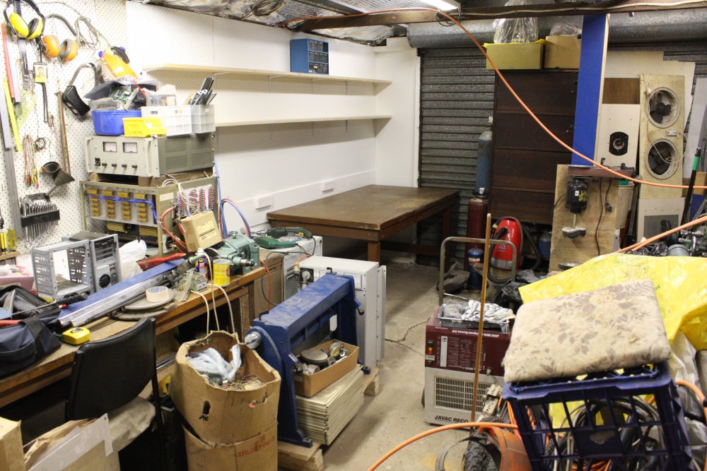
5. Test placement. Gosh, it looks nice when it's all empty and clean. So much space!
(And I know exactly how long that will last.)
The intended purpose of this bench is:
- At right, the big HP DC power supply, sitting on top of the even bigger passive dummy electrical load. I need these things set up for use, rarely to be moved since they are so big and awkward.
- Center area of the desk for a custom 3D printer project I want to do. No point going into the specs for that now. But it will be a fairly large one, so needs space.
- Left end, for a radio system use and repair area. In general this bench will have some electronics test gear. Low cost robust stuff, which will normally be under covers to protect it from the 'room of flying daggers', aka iron filings from grinding, which for electronics might as well be flying daggers.
I expect keeping the bench clear of other junk and dedicated to those specific aims will be quite a battle.
 |
 |
 |
 |
 |
1. When I'd started, I'd intended to only do that much. But now I'm all enthusiastic about the reorganization, have a wet paint roller and tray in a bag, and plenty of paint. I want to paint more things! All the things! Heck, why don't I do the rest of this wall space? My tools pinboard arrangment had become more and more random over the years, and by now is just... ridiculous. Also next to the nice newly painted white it looks grungy too.
2. So off they come. Getting the hooks off was a bit more of a chore, since about half of them I'd hot-melt glued in place. I'd become sick of them falling out as I lifted tools off. Pulling them loose and peeling the hot-melt messed up the paint surface, but who cares, it's all getting repainted.
3. More wall to insulate with glass wool. But then... the pinboard has holes, and I don't want glass fiber dust shaking out through the holes forever. But if I put foil flat behind the pinboard, the hook ends will puncture it as they are inserted through the holes. Sigh...
4. And so this. It's a tough woven and sealed film, stapled on with plenty of slack so it can be pushed back a bit behind the pinboard. Good enough.
5. Ready to paint.
 |
 |
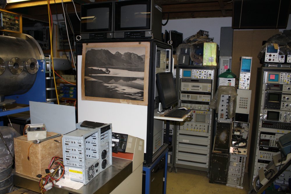
1. Meanwhile, back in the electronics lab... By now every bit of visible free wall space is gone. And yet, I like to keep this very old B&W poster of Lake Pedder in Tasmania (as it was before being flooded by the Gordon River hydro-power scheme in 1972) in a prominent place. It reminds me of goals. I wanted to put it on the side of this equipment rack, except there was no side. But I had a suitable piece of plywood, and a wet paint roller. So a small diversion to cut the panel to size, paint it and fix in place.
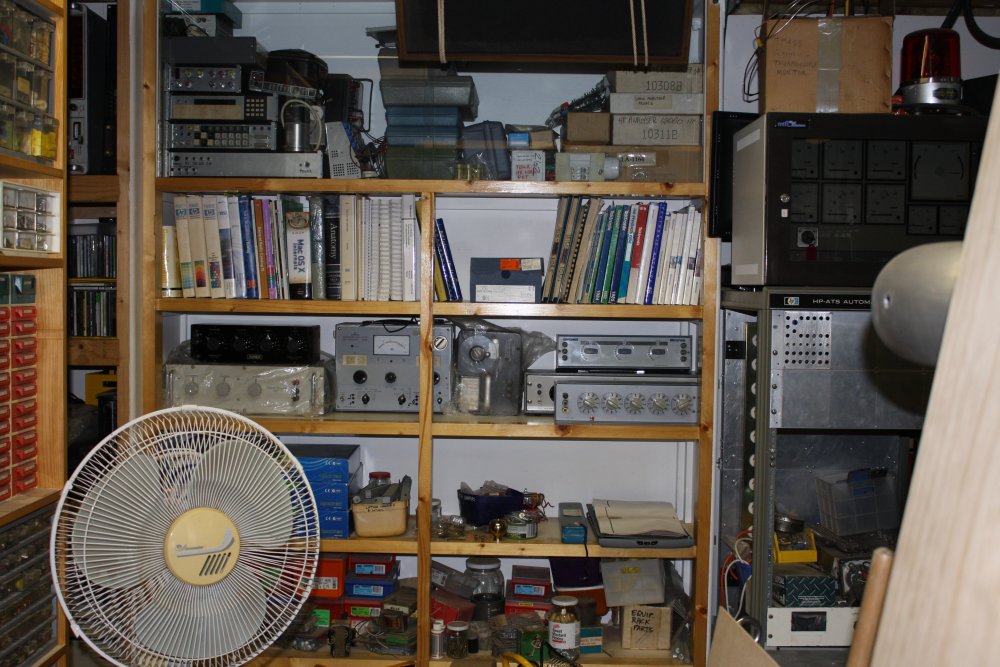
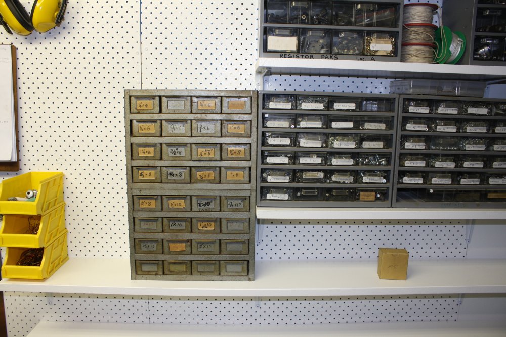
2. Elsewhere in the room, these shelves are supposed to be all for books and test equipment. Till recently they've been piled with boxes and containers of nuts, bolts and screws. In anticipation of completing the shelves in the other room I've moved them off two shelves here. So now there's books and instruments. And there will be glass-inset doors too, if this place ever gets finished (not helped by government plans to bulldoze the entire area.)
 |
 |
 |
 |
 |
1. Planning? What planning? With all those boxes of screws sitting on the new bench and floor, thinking about how to arrange them on the new shelves, it was immediately obvious there wasn't enough shelf space. I wanted to have the parts drawers and the bulk boxes of fasteners handy. Nope, not going to fit.
After painting the pinboard I'd also started arranging tools on it. Prematurely naturally. Now apparently I'll need more shelves, and the tools will all have to come off to start again.
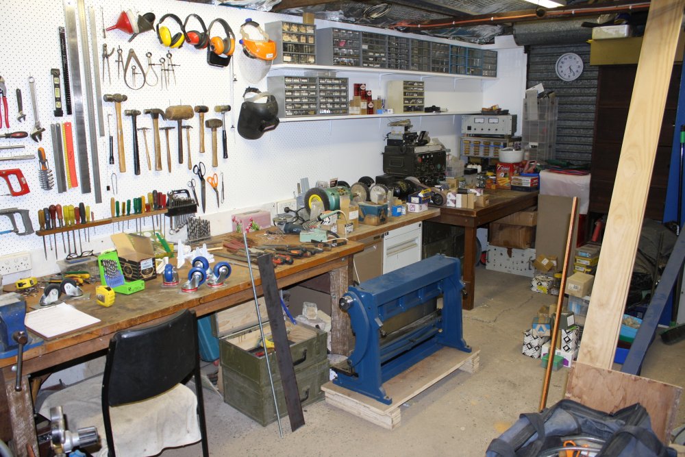
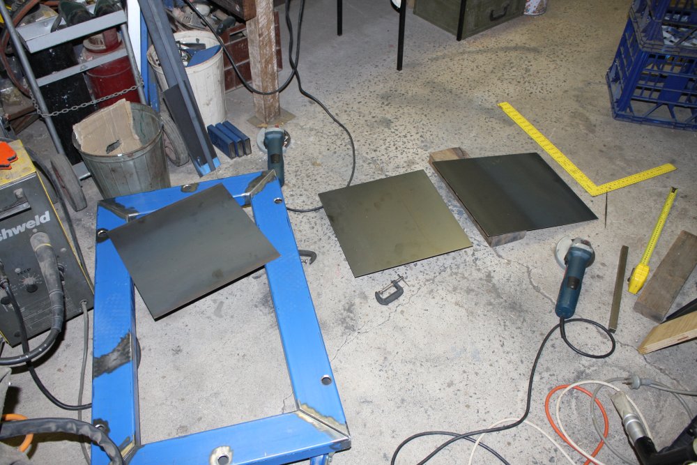
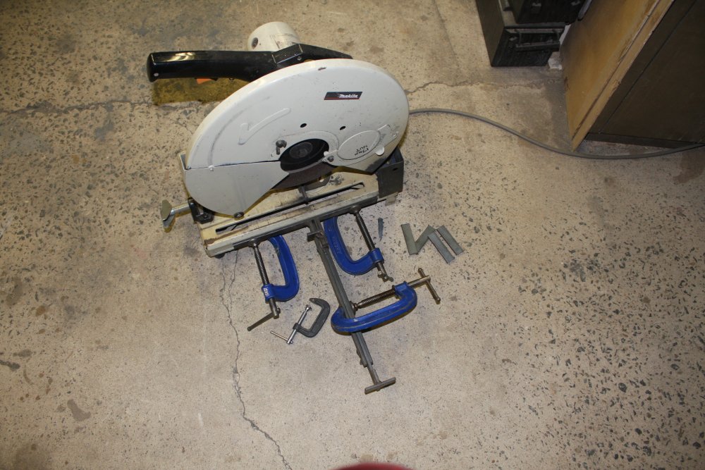
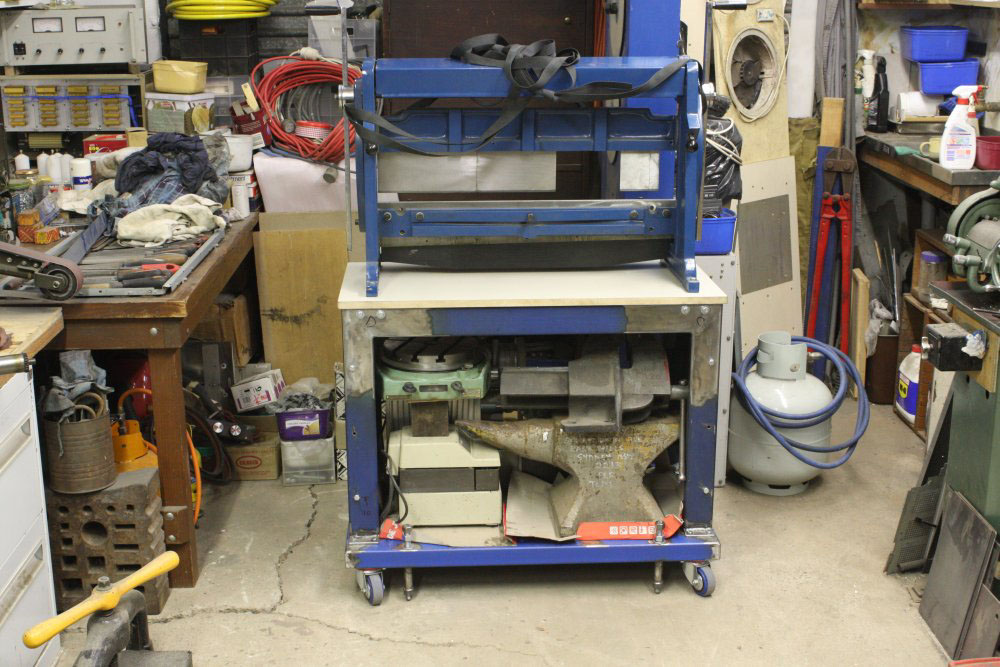
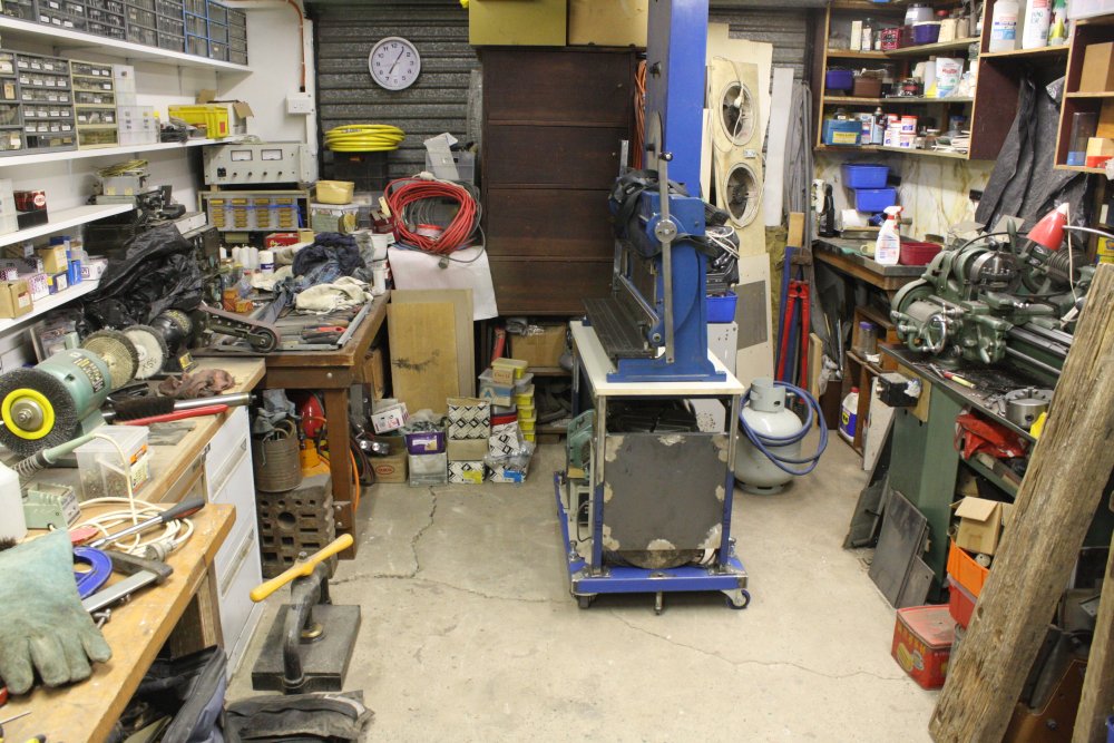
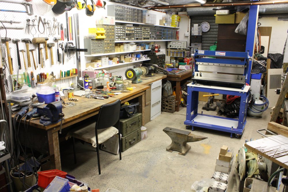
Also see the big blue sheet metal machine sitting on the floor, where it's near impossible to use? And there's another pile of things on the floor just out of view to the right, that can't stay there. Minor little items, like an 80Kg full size blacksmith's anvil, and matching swage plate that seems to weigh even more. They are destined for a different workspace, but not for a while yet. Plus... well several equally big, heavy and awkward objects.
By now a single solution to all these problems had come to mind.
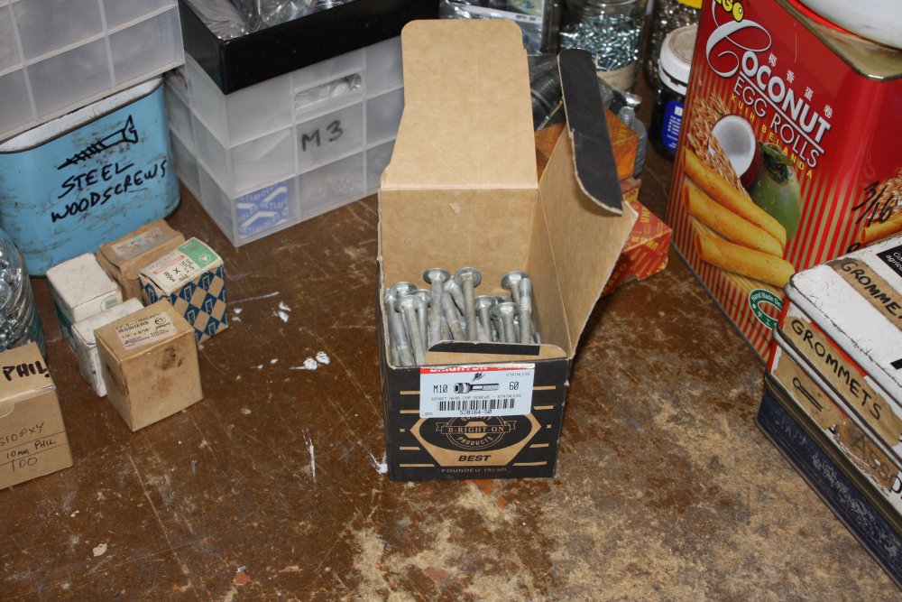
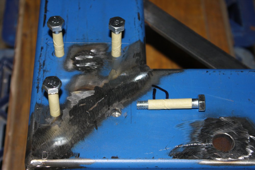
2. AH HA! In sorting through the boxes of fasteners sitting on top of my old bench, I found the missing bolts for the bench. Oh now I remember... I'd been in a rush, grabbed an empty box for them, and meant to label it later. Forgot. The box's original "M10 Machine screws" label was pretty good disguise for some cup-head imperial wood-bolts, hence not finding them when needed. How ignominious. Also ironic, to open this box on this table. Ah well.
3. Spot the difference from pic #1. Just some wood for extra shelves, and some steel bits for the metal folder base. The point of this photo is that it marks the moment at which a simple 'bench and a couple of shelves' project blew up into several rather more complicated projects. Why does this always happen? OK, yes I know, little or no planning...
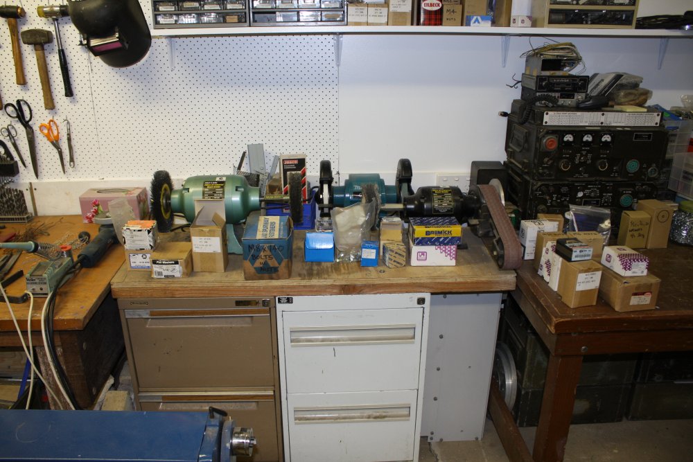
4. Something I'd like to point out. I made this base for the bench polisher and sanders a couple of years ago. Now when I put it here between the two benches it fits perfectly. I've had the idea my old bench would end up here for about that long. I think I did actually measure things up when making the polisher base, and this nice fit wasn't a fluke. Probably.
I do need to rearrange the positions of the machines on the base though. But that's easy. (It's not going to be piled with boxes like that, of course.)
What I didn't plan, that was nice, was finding my huge and heavy industrial battery charger unit that had been part of the junk heap, just happens to fit perfectly in the space to the right of the filing cabinets here. I mean perfectly, the meters and knobs each just clear the bench beam and legs. Lucky!
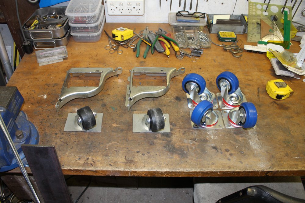
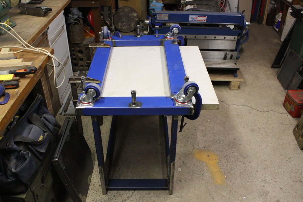
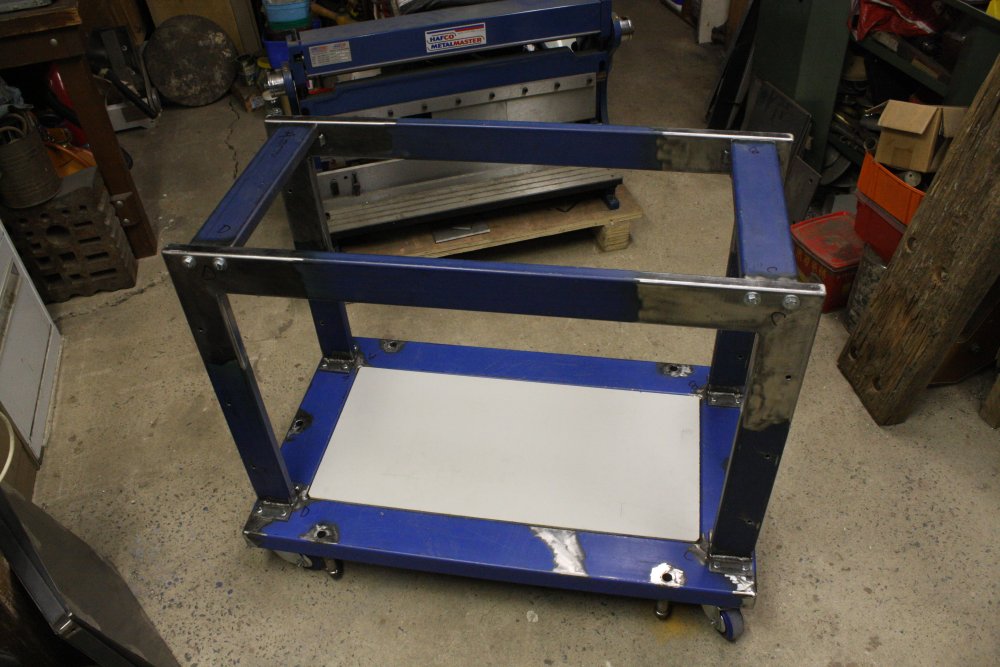
5. I knew I shouldn't have let myself feel pleased about (probably) having planned the polisher base size so well. Now I started thinking about the base for the metal folder. It needs to be on castor wheels, so it can be moved around. Big heavy duty castors, since the folder weighs a lot, and the base will also be used as storage for the anvil and stuff. The two on the left came on one of my HP instrument racks. I'd cut them free of the useless custom metal brackets. They'd be perfect for the folder base... if only I had four.
I have two of those racks. They came at different times, a couple of years apart. Both had a pair of these castors. But can I find the pair from the first rack? Nope... Yet I'm pretty sure I didn't throw them out.
Bah. So I bought new castors — the four on the right. I'd much rather have found the two missing HP ones, as they are far more robust. Still, here came the second in a row serendipitous events with this project. I couldn't find a nearby industrial castors supplier online. As expected. Ones from Bunnings are too weak. Where would I get them? Happened to ask at Premier Fasteners in Milperra, and surprise surprise there's a great place that specializes in industrial castors just around the corner — Style Steel, 23 Fitzpatrick St Revesby. I did not expect it to be that easy.
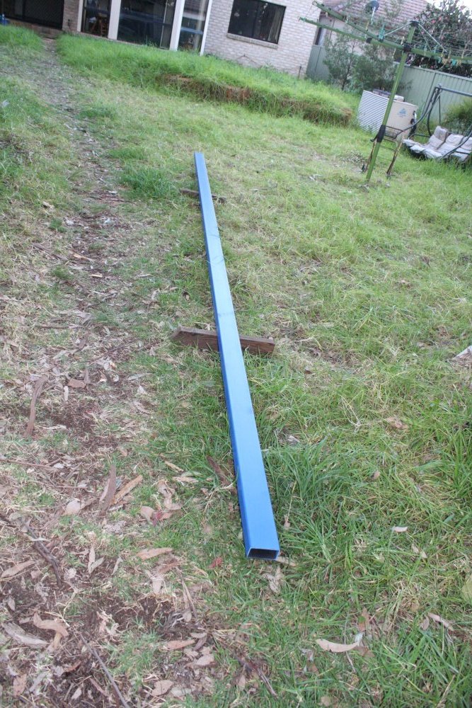
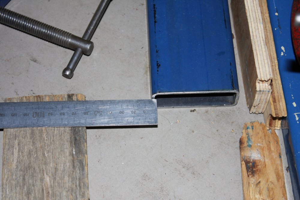
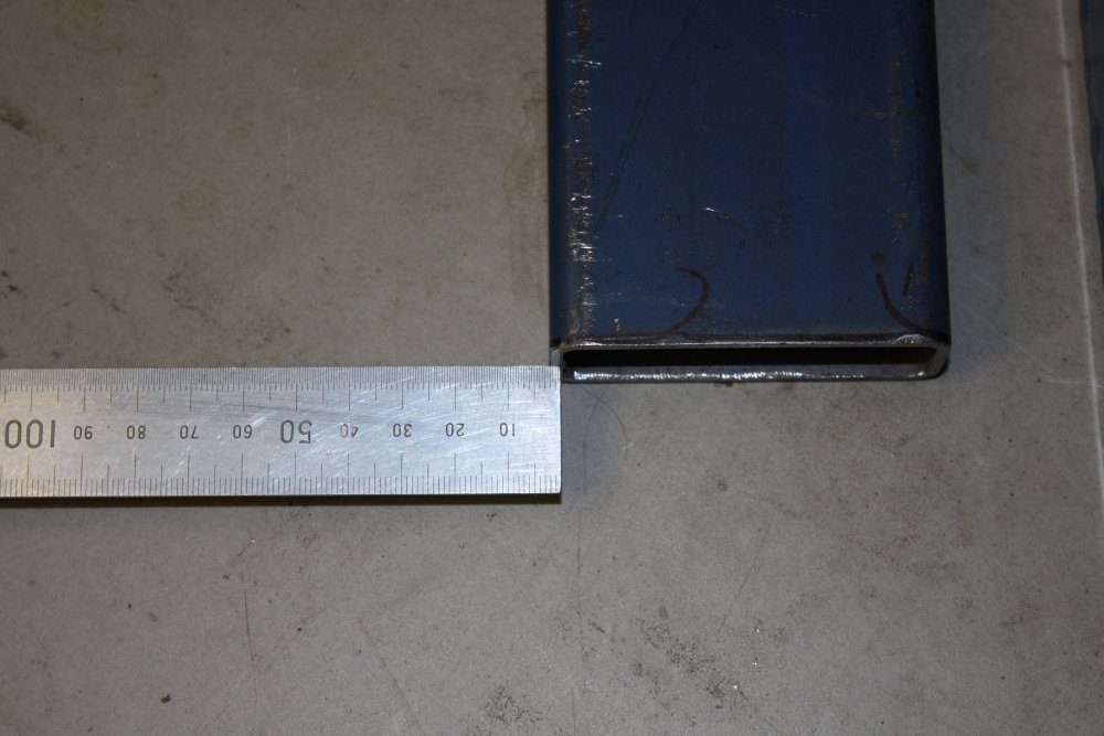
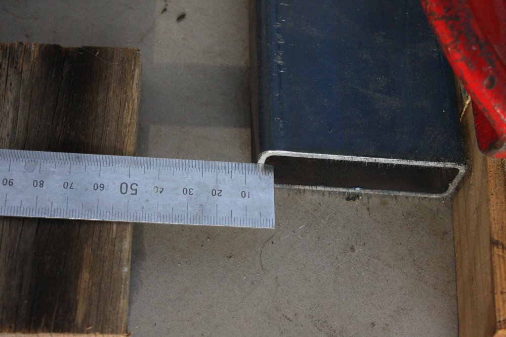
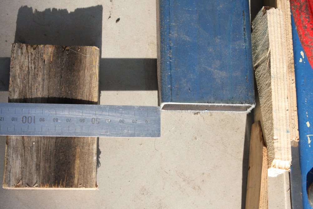
Then on the same shopping trip I went to a steel supplier for pieces to make the folder base. I needed a little under 3m so asked for 3m at the steel supplier. This means cutting it from the usually 7m long sections. The 100mm x 50 x 3mm wall rectangular section, is $18.83 a meter. Buying a full length is overkill and anyway I can't transport it on my car roof racks. (Well I can and have in the past but it's not legal on the road.)
So I'm there in the warehouse, and the guy pulls a length off the rack, and carries it over to the cutting machine. I think hmmm... that's not a full length, it's a bit over 5m. The cutting fee is $7.60. They'll be left with a barely saleable 2m offcut. So I asked if I could just take it as is, for the same price. They agreed. Juuust little enough overlength that they'd say OK, and also juuuust short enough in total that the warehouse guy would look the other way while I put it on my roof rack. Should really have brought the bumper bar bolt-on front support to be legal. But it's a brief drive and back streets all the way.
Wheee... free steel, due to luck that they had a piece that size.
To round out the streak of coincidences, also at the steel supplier when paying in cash the bill was $68.30. Turned out I had exactly $8.30 in coins in my wallet. I love it when stuff like that happens.
 |
 |
 |
 |
 |
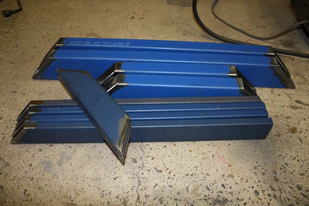
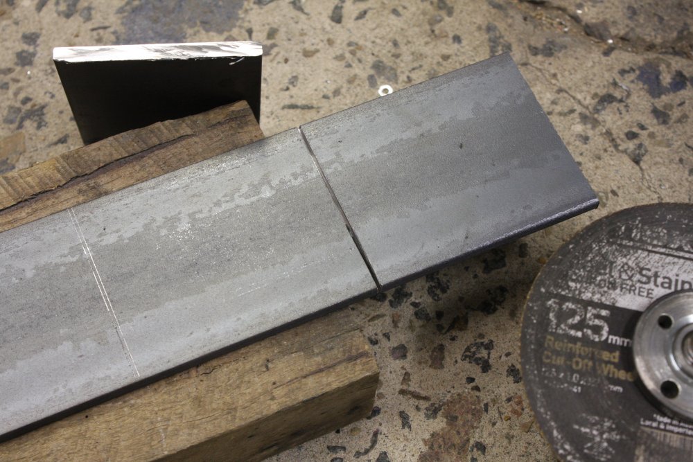
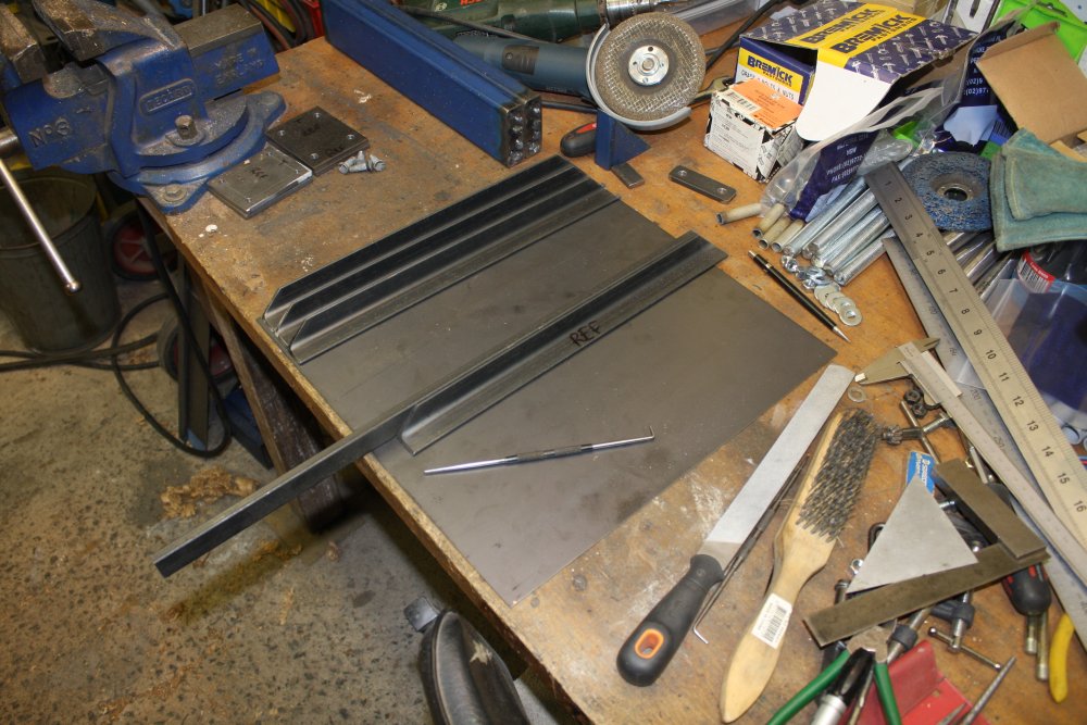
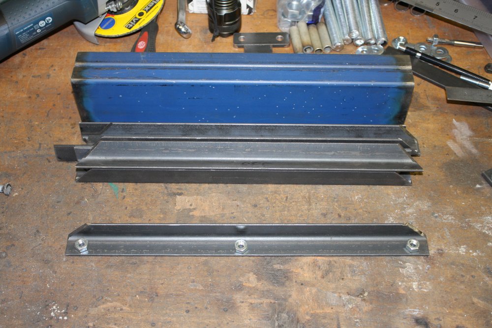
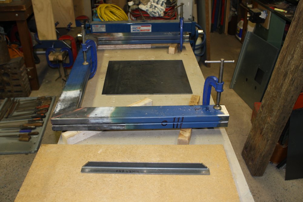
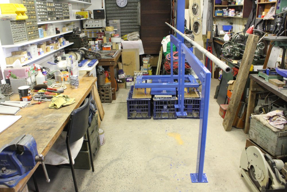
1. The base for the sheet metal folder/cutter is going to be something of a beast, and a significant amount of work to build. Should I give it a name? Yeah, why not? Here is the piece of steel most of it will be made of. So how about Project Blue Beam? Ha ha ha... some of you will get the joke. Though what you'll find via google is all well poisoning disinformation garbage.
2 - 5. But wait, there's more... diversions.
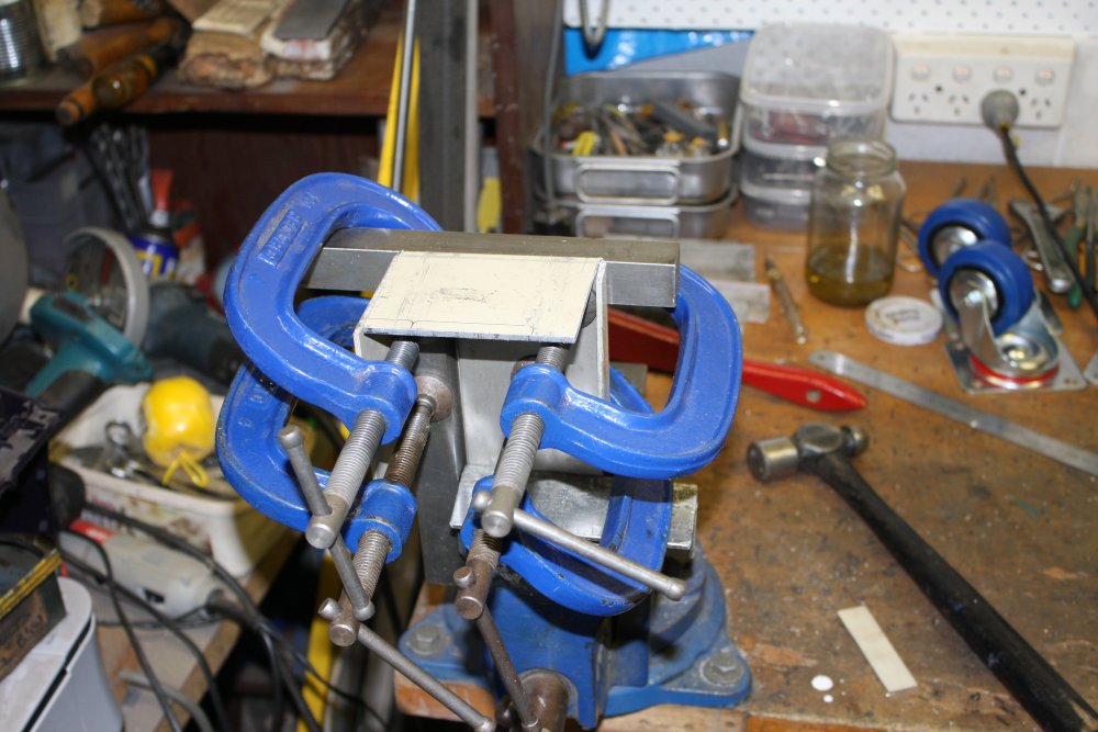
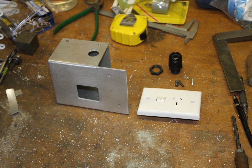
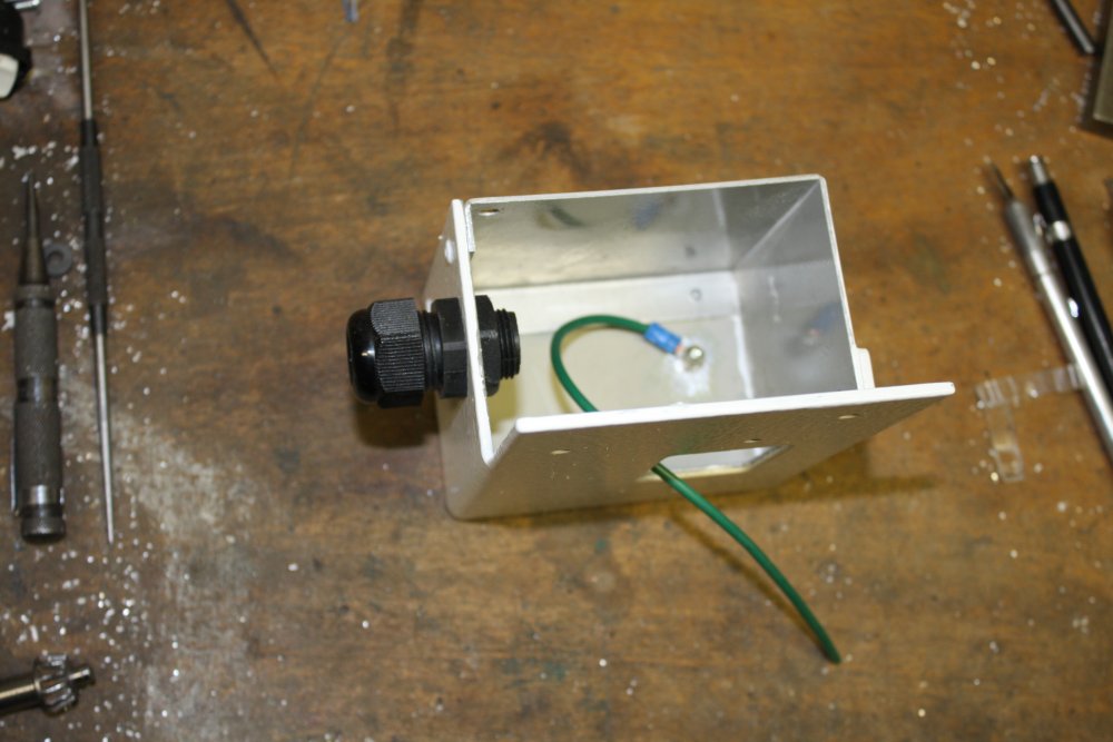
As well as the new standard mains outlets for the new bench, I wanted one 15A outlet there (because my huge HP 6269B 0-40V, 0-50A DC power supply requires it.) But there's no suitable wall space to mount it. And so, need to make a mounting, which should be fully enclosed.
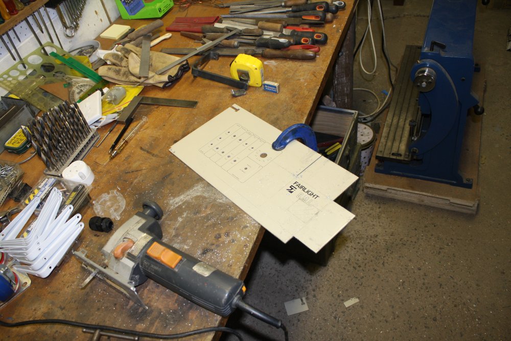
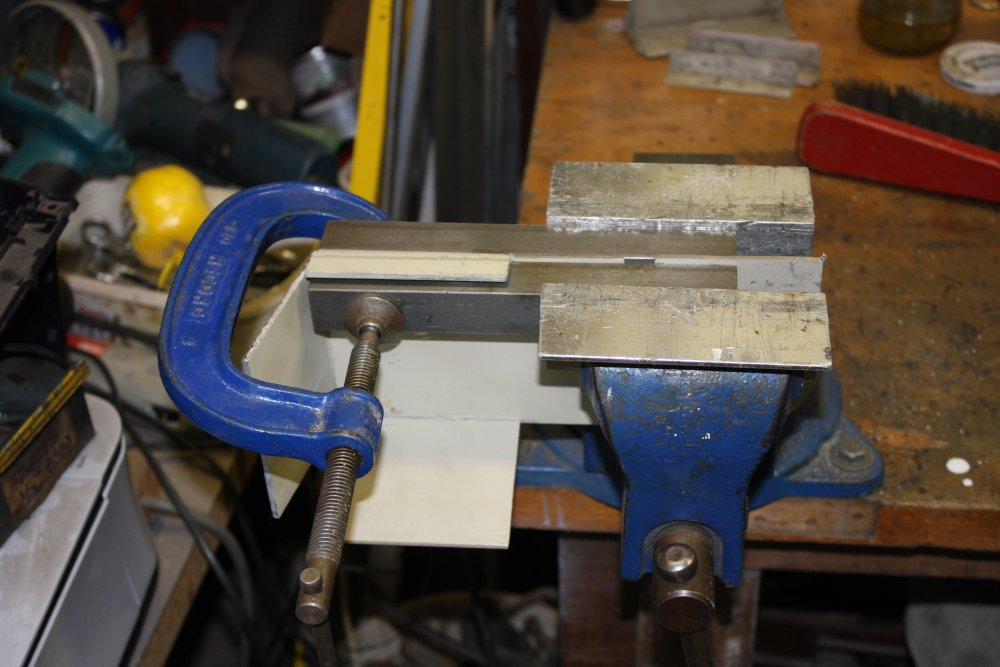
A little history here. Long ago I used to work for a company called Fairlight Instruments, who made music synthesizers in the early days of microprocessors. One day they were tossing out a lot of obsolete metalwork. I asked if I could have it and was told yes. So among other bits I have a foot-high stack of Fairlight CMI Series I front panels. Which are 3mm thick aluminium, and despite some holes have been extremely useful for random projects over the years.
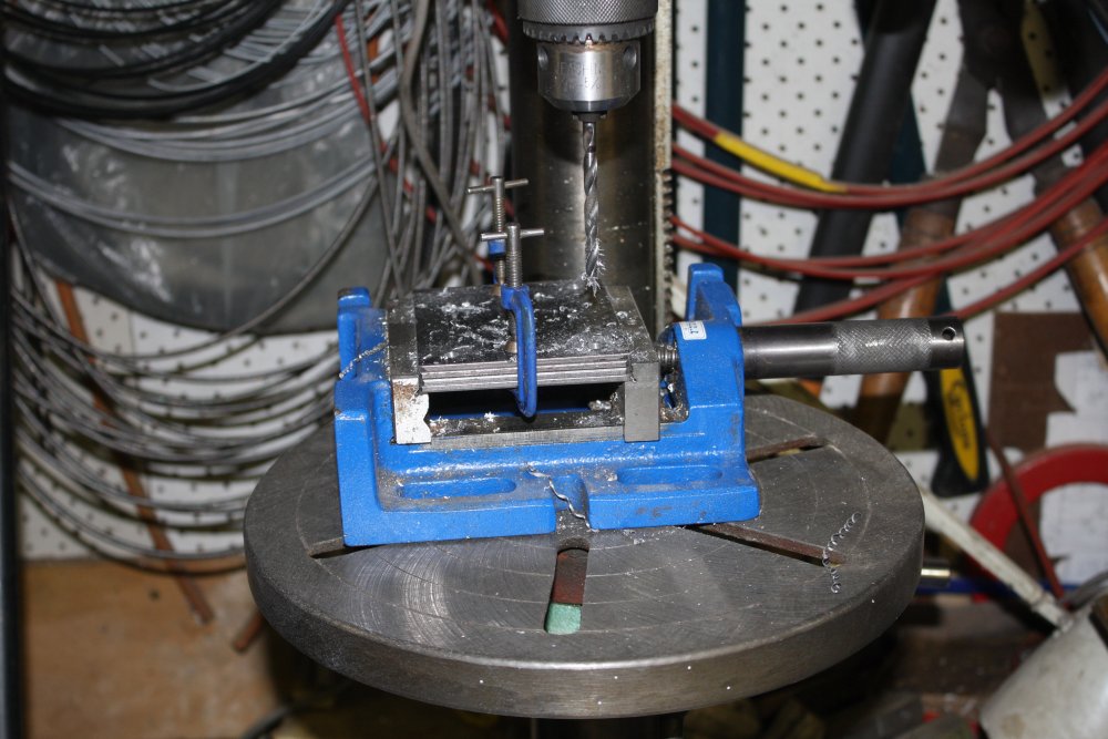
Here's one being cut and folded into the power point mounting enclosure I wanted. And incidentally, a tip for cutting thick aluminium with a jig saw. See the glass syringe on the bench? It contains kerosene. Run a small amount of kero along the cut line before starting with the jig saw. It prevents the soft metal cuttings from sticking to the saw blade, and makes the cut run far more smoothly. Use the same trick when filing aluminium - put some kero on the file blade first. Immense improvement!
 |
 |
 |
 |
 |
1 - 3. I keep mentioning possums so here's a possum, and her baby. This is just outside my workshop, where they belong. Outside.
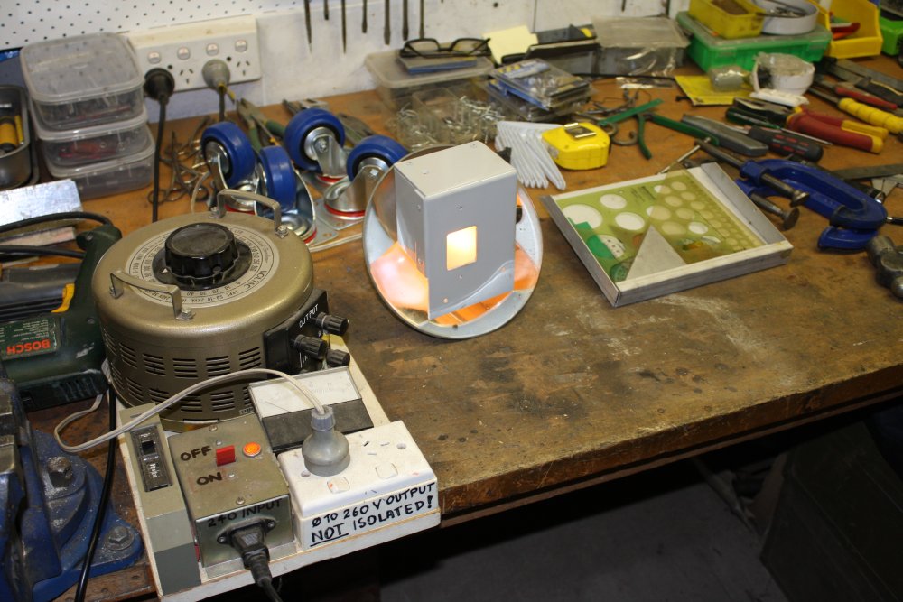
4. I'd spray painted the 15A power point enclosure, but the paint was taking ages to dry to where I'd hope a 2nd coat (of the white paint) would work. So improvised a gentle heater with a 240V light and my big variac.
Just to the right of the lamp is another diversion. On the old tool pinboard arrangement I'd kept a few plastic drafting squares and circle stencils in a pile behind the screwdrivers. Wasn't a very good arrangement. Also I have a great metal folding machine, so why not do some kind of stand/holder for those things? This is it, partially complete. It will hang on the pinboard.
5. Like this. The bottom is spaced out from the board, so the set squares lean back. Also there's a rod to prevent them falling out to the front. The rod ends have circlips in grooves to hold it in place.
The other huge innovation (ha ha) in this image is the bit of gray bench backboard at left. For years there's been a gap there due to no wall stud at the left to screw anything to. Now it's fixed to the cabinet. Nevermind, it works, and finally I won't be dropping things down the back of the desk there.
 |
 |
 |
 |
 |
1. I dithered a lot over the length, depth and spacing of the extra shelves. These ones are to hold smallish boxes of commonly used screw sizes, mostly metric. No parts drawers here. How much of the tools pinboard should I sacrifice? How many boxes deep, to not hide some of them? How much vertical spacing? Numbers weren't relevant, I mainly tried to visualize the ergonomics of using it frequently. In the end I just marked positions by eye where I thought they should be. Screwed the brackets on, and this is the result. Shelves not painted or screwed down yet. Also the polishing machines will be moved forward on their base a lot.
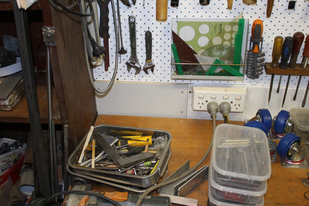
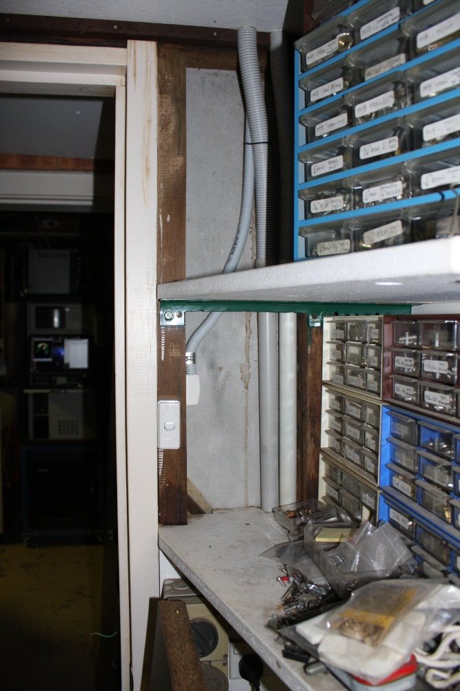
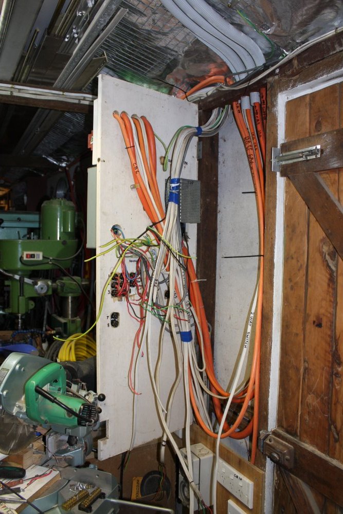
2. Another diversion. The light switches for this workshop are just inside the external door. This has been a problem ever since I added the passageway between buildings, since it means I have to walk a few paces into the room in the dark when entering. Which, given some of the stuff that can be on the floor in here at times, is really dangerous. So I'm adding a two-way master switch for all the lights. This switch is at the entrance from the electronics lab.
And here's another serendipity. I had some remainder of 20mm flexible conduit from a previous project a while ago. Thought maybe it would be enough for this, so started installing it (loosely) from this switch end. Only way to find out for sure.
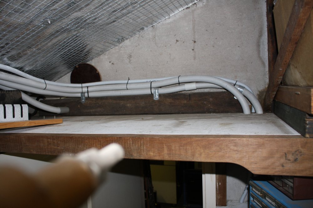
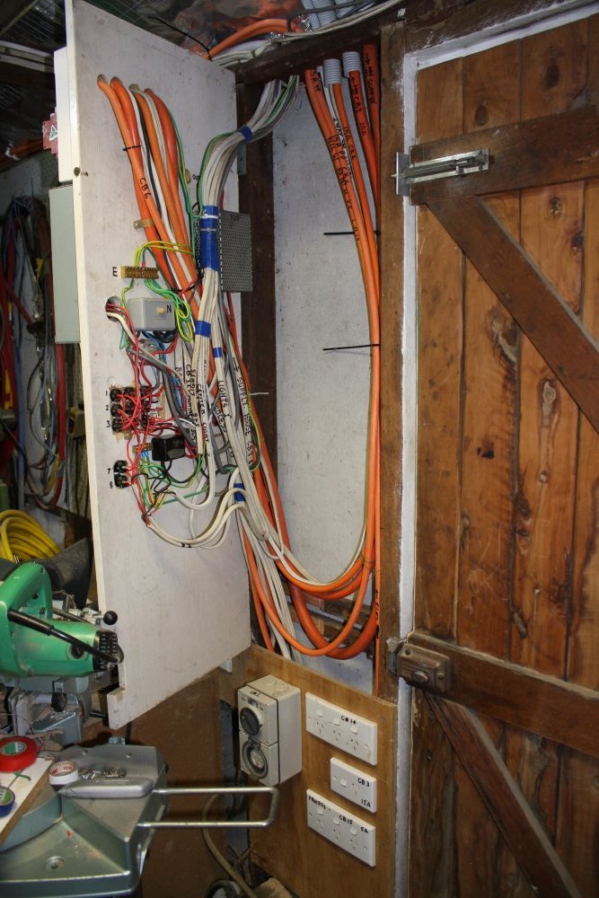
3. Up the wall, across the ceiling...
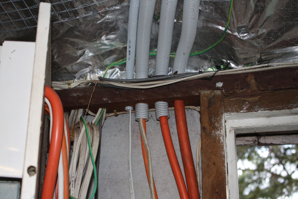
4. Ending at the distribution board. The left-most conduit. No, I didn't have to cut any off, that's just the end of the random length I had. Amazing...
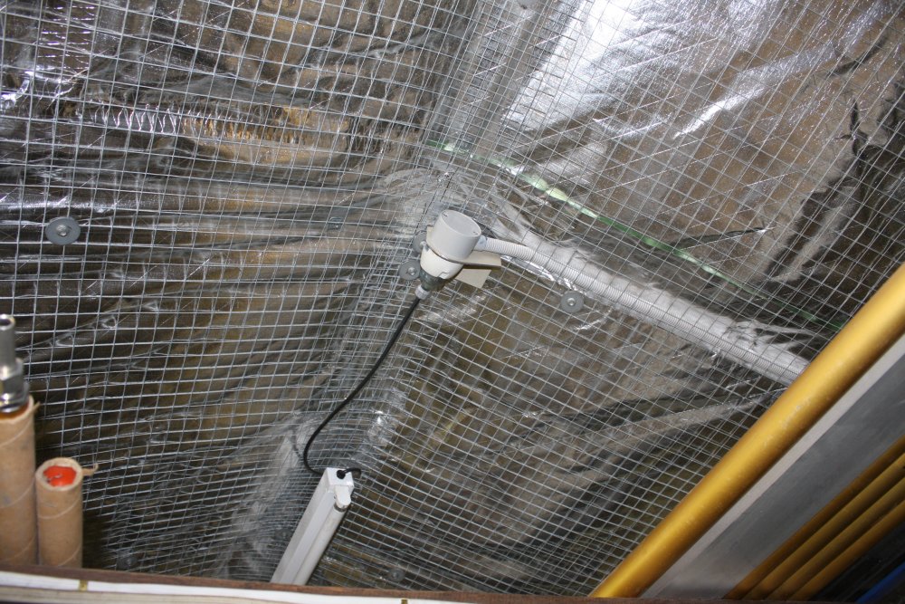
5. More unplanned extras. The room lighting also had the problem that there's no one single low power light able to illuminate the whole room, for leaving some light on for long periods of intermittent use. So added this one. All the other light battens have 3-pin sockets, mounted on beams. But for this one at the roof peak there was nowhere convenient to mount the outlet. Hence the constructed bracket. Yes, properly grounded and insulated. Incidentally the wire mesh mechanically protecting the foil (that protects the glass wool insulation) is solidly grounded too.
 |
 |
 |
 |
 |
1. That 15A outlet enclosure again, inside view.
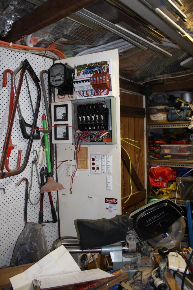
2 - 5. Wiring upgrades. This shed has two independent supplies; one original single phase 20A circuit via RCD on the house board, and three-phase 32A from the main workshop.
 |
 |
 |
 |
1. Cool! Remember I said the extra shelves were not measured at all? So I have this old tall metal parts drawer unit, containing a range of self-tapper screws. I'd envisaged it would go here where the extra height would fit (no shelf above), but I didn't expect this perfect alignment of the tops. Not that it really matters, but it's satisfying. No honestly I didn't arrange that, it's a total fluke.
2 - 4. Coming along. It's also a fluke that another old odd-size set of drawers containing assorted stuff I wanted to keep as-is, happened to fit exactly in the remaining end shelf gap. Nice, thanks Karma, or whatever is happening with all these coincidence-fits.
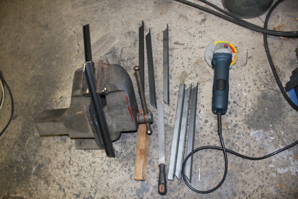
So, what's with all the files in a row on the bench?
 |
 |
 |
 |
 |
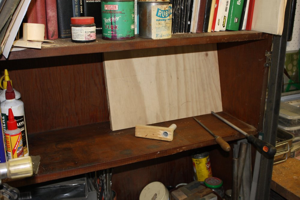
1. Well, they used to all sit in a jumble in a cardboard box in this shelf. This is really bad - you shouldn't let files touch each other as it blunts the sharp points. I'd always put files down in there gently, but still... it's bad.
I'd been trying to think of something better for a while. So has everyone with lots of files, and there are are many different solutions, none of which suit my shortage of space and cash. What I wanted was some way to store them compactly, yet individually protected and still visible to allow easily selecting the needed one. I'd thought something like a knife block, except with some of the file blade exposed. And done with minimal, cheap materials, ie no huge block of wood.
Also bonus if the same system could store wood chisels.
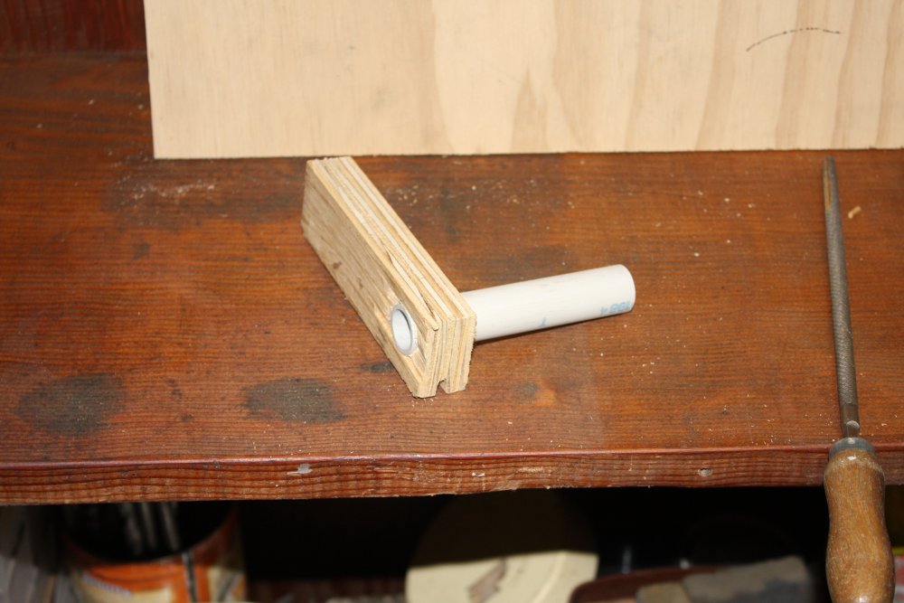
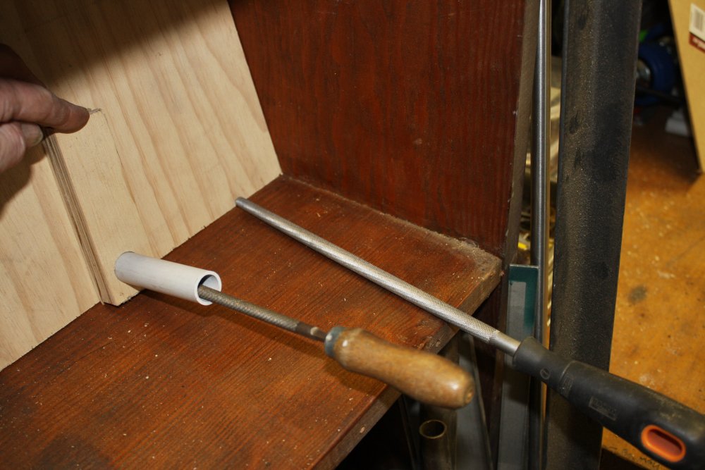
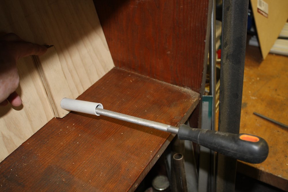
2 - 5. Here I was experimenting. It seems like a board with short sections of various diameter PVC tube may work well. There'll be a backing board so the files sit on their ends, slanted down a little so they don't fall out, and with most of the file body exposed. The sole remaining problem I can see is that for large files and chisels a flattened pipe would be best. Still working out how to neatly heat-shape bits of the tubing for the flatter section, plus make neat matching holes in the wood for the non-round tube pieces.
More on this later.
 |
 |
 |
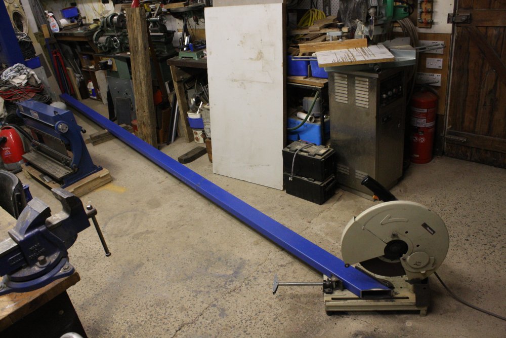 |
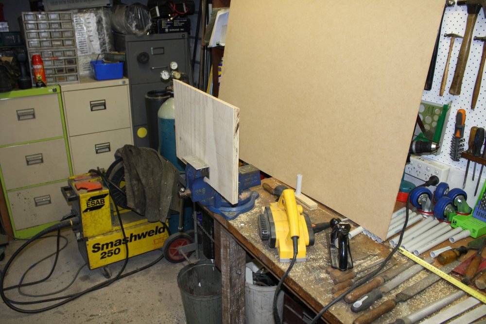
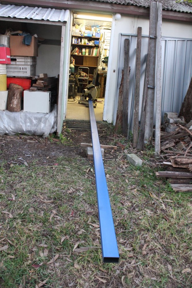
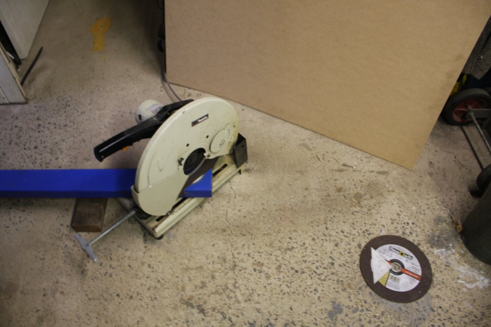
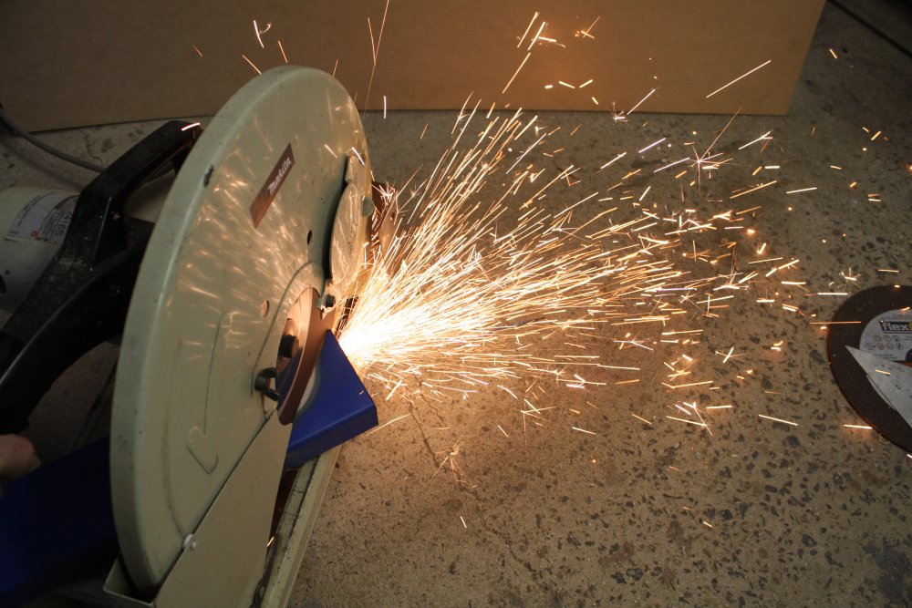
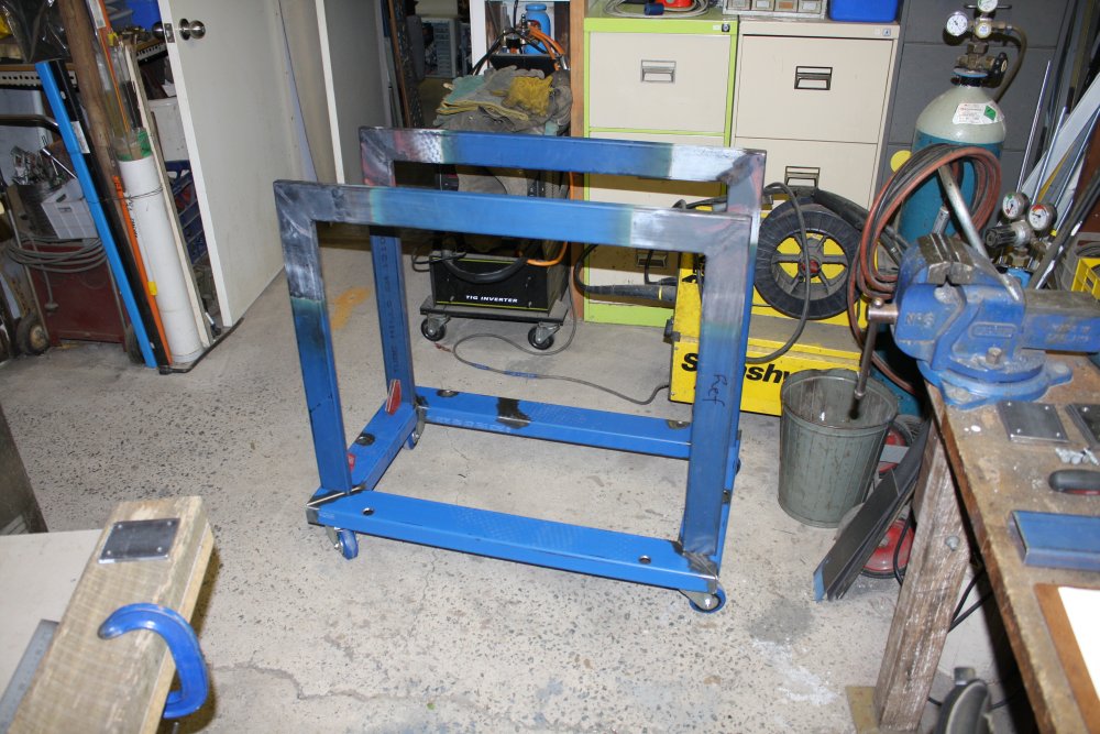
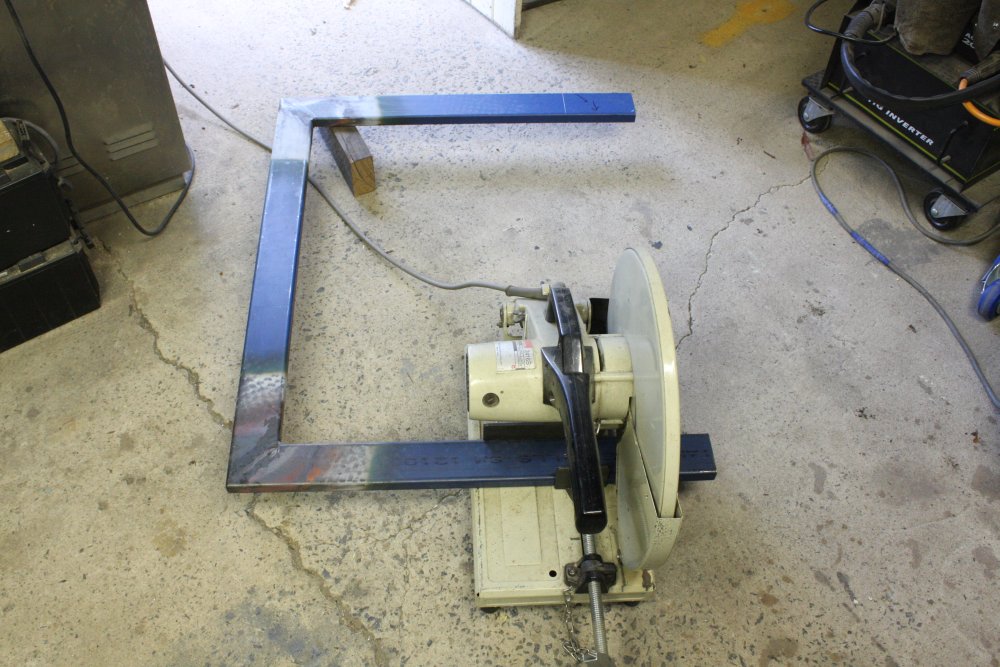
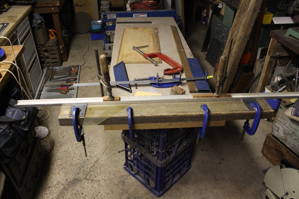
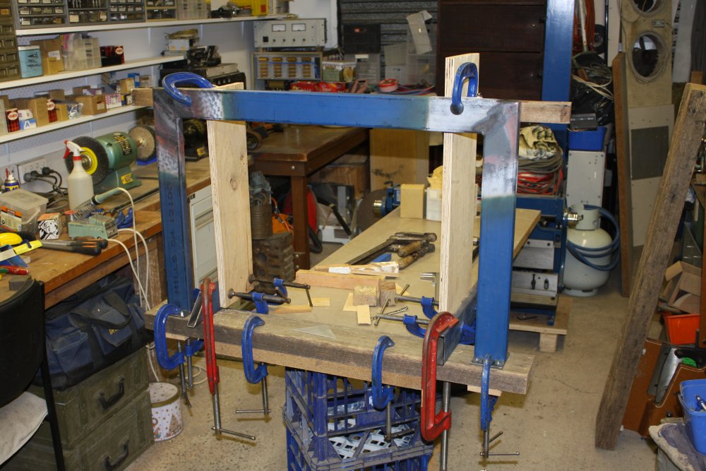
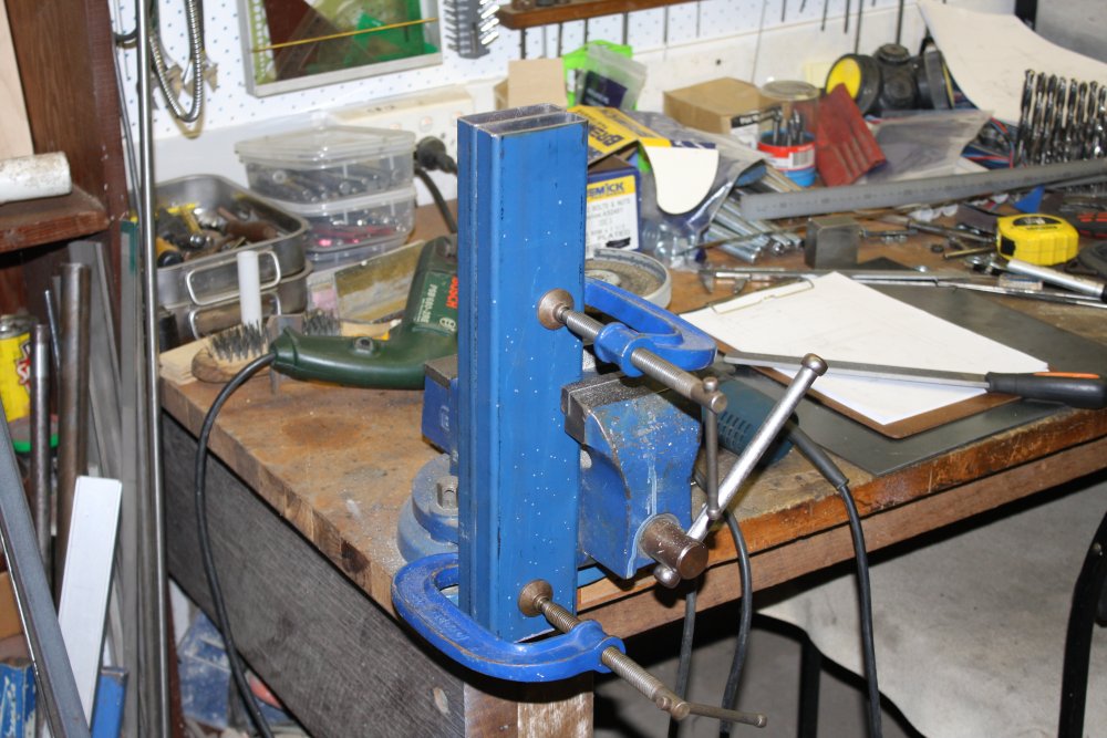
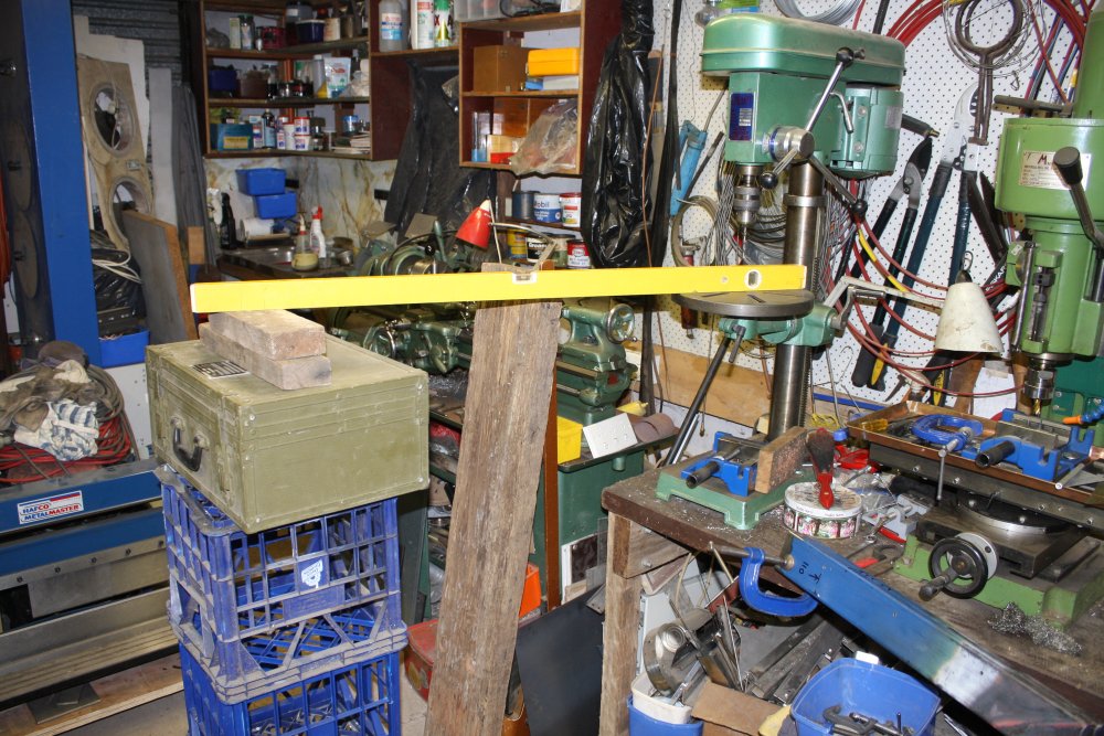
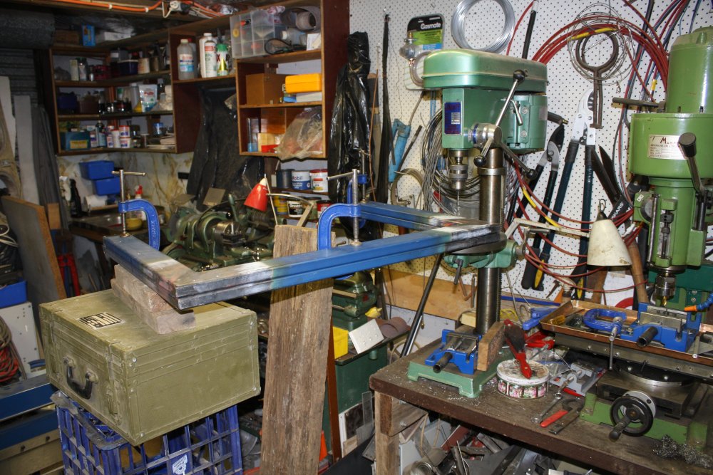
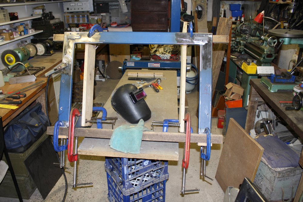
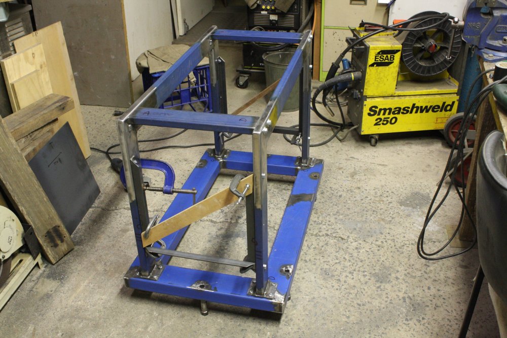
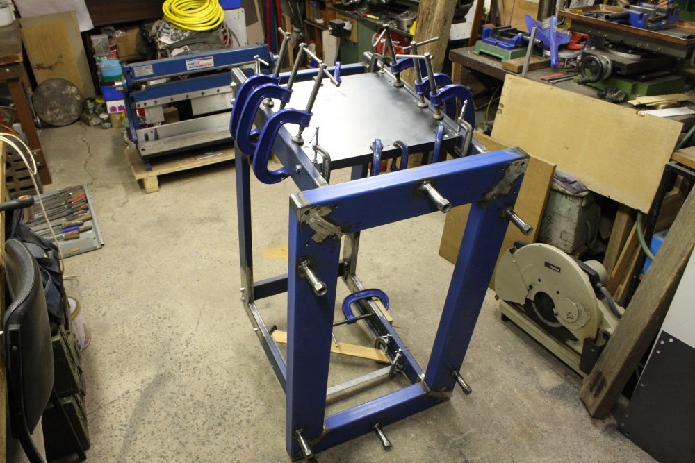
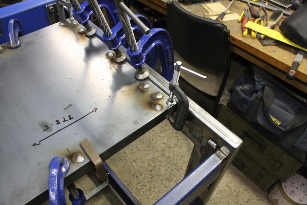
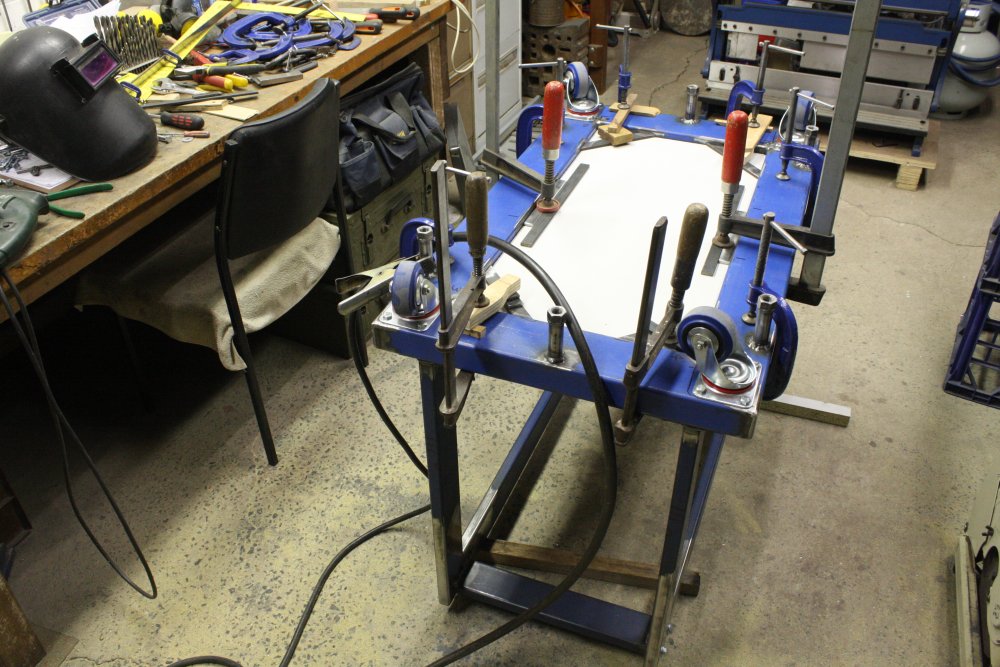
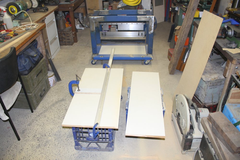
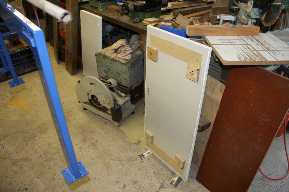
1 - 3. Back to Project Blue Beam. The unexpectedly long section I'd bought presented a slight problem. It looked way too long to manoever in through the doorway to the workshop. There was no problem storing it in another building, but working on it seemed to require this arrangement.
4. Also I'd had a bad cold at this time, and so the idea of carefully manhandling that beam around (it's very heavy) didn't appeal (read: I felt rotten and weak.) But finally I got annoyed enough with this awkwardness to just try it.
Another amazing fluke! Apart from being like a cross between weightlifting and ballet, the thing fitted, but in the most extremely marginal at multiple points way I've ever seen.
 |
 |
 |
 |
 |
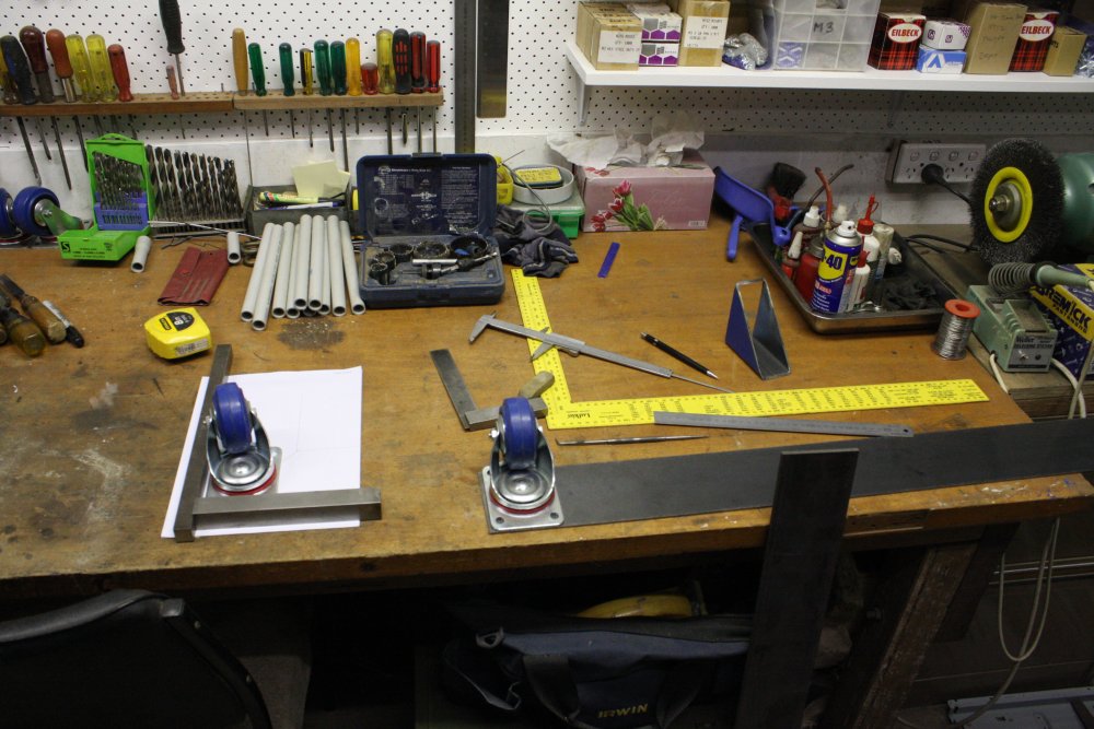
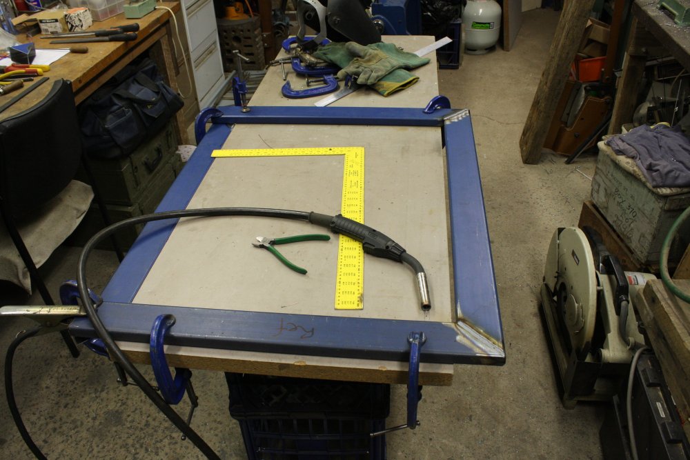
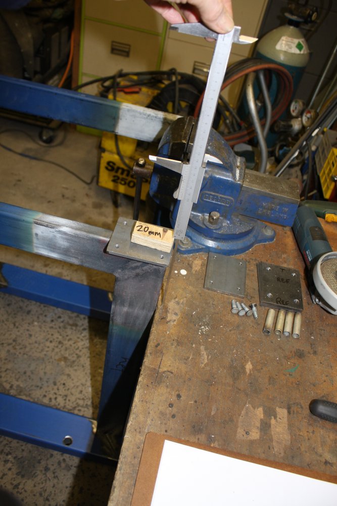
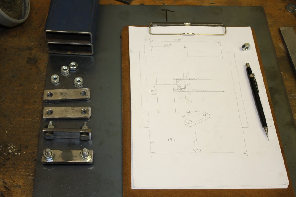
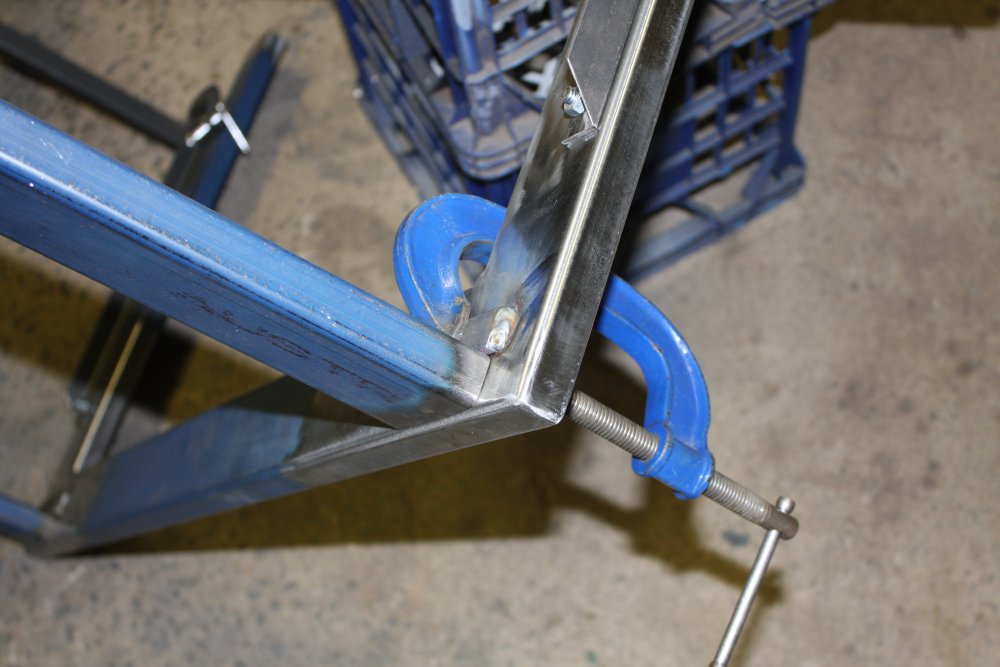
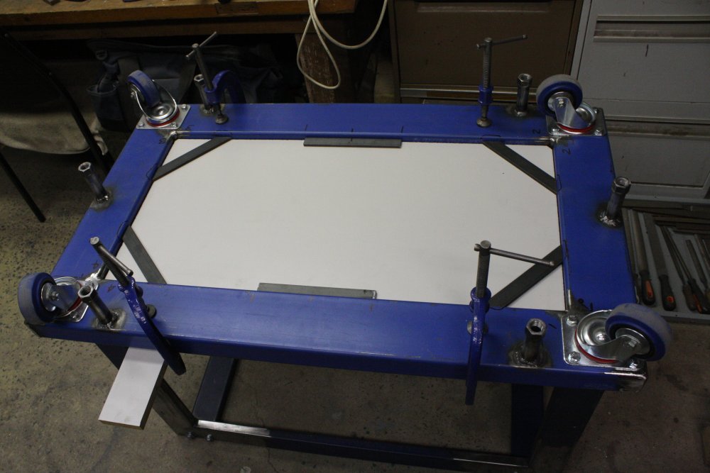
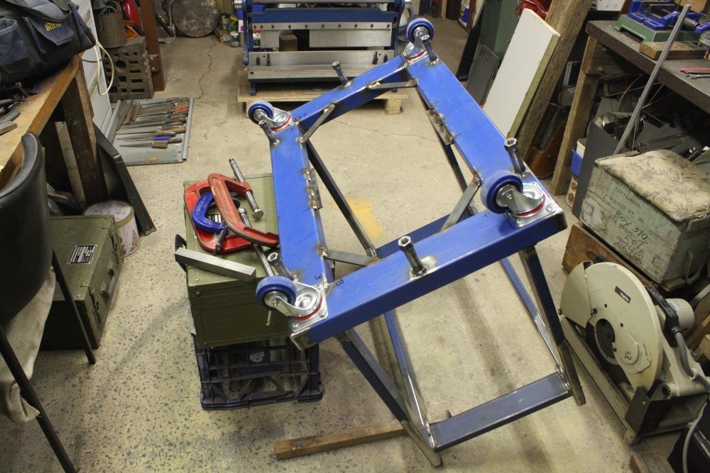
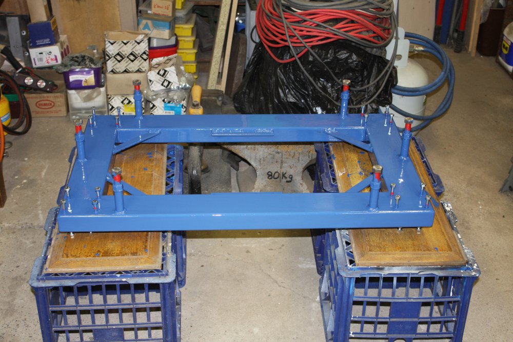
1. Using a full scale paper drawing of the base frame corner to work out where the castors and screw-down stands would go.
That was on 2nd October. The cold I'd had seemed to be getting better. Then on Oct 3rd I went to a party at the top of some sea cliffs, stayed up all night, inhaled some fumes from a burning PVC banner someone threw on the fire, and later in the cool sea breeze had a short lie down around 5am on the rocks overlooking the sea waiting for sunrise. It was all great fun. But boy... I don't know if I caught a different, new flu, or just handed the old one the keys to my body. For the next month I was very sick. I think something extremely worrying and depressing that happened in my online world starting around 4th Oct didn't help either. It took several days to get back to this project, and it slowed down greatly.
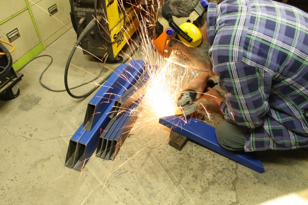
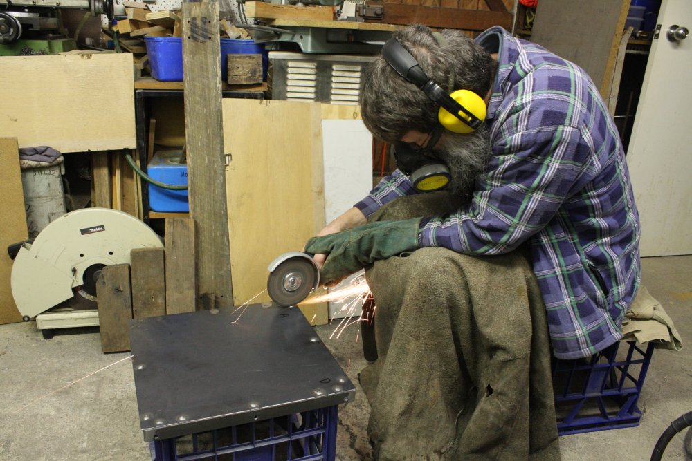
2. After cutting most of the pieces for the base, there's a lot of bevelling of weld edges to be done. By hand with a grinder.
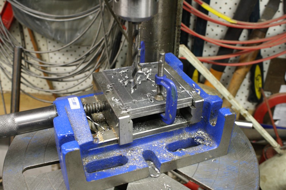
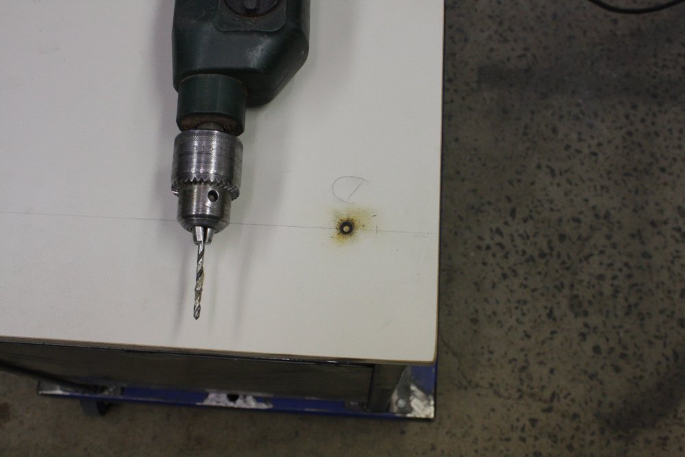
3. The castor wheels will bolt to the frame, via plates with welded-on nuts inside the frame. Here drilling those plates.
4. The large pieces for the base. Quite a lot of planning went into the design on paper before cutting up steel like that. And yet, as we'll see...
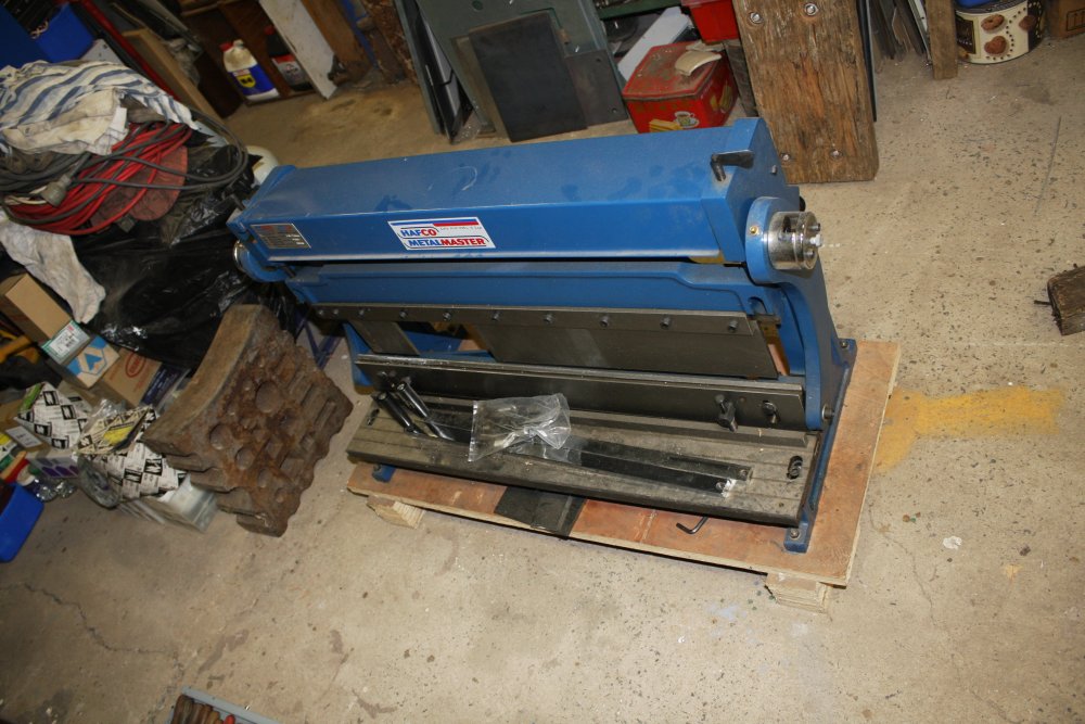
5. A better view of the sheet metal working machine. This will always be used while I'm standing, and so I wanted it at a comfortable working height. The conflicting requirement is that in operation one pulls very hard on levers near the top of the machine, and a lot of this force can be sideways. If the base is narrow, that presents a risk of tipping the machine over (onto myself, which could be fatal.) There's also a need for solid cross bracing of the stand, while preserving maximum space in it for storing things. What's the best solution?
In general the best approach to the design process is to break the overall requirements into sections whose reqirements interact as little as possible, then solve each one independently. While keeping a holistic overview and being prepared to alter the section factorings if better solutions appear as you become more familiar with the overall problem.
Pretty fancy words for welding up some steel, right? Well, bought steel isn't software source code on a disk. It's not so easy to edit after a goof or when you change your mind.
For Project Blue Beam (sorry, I just think the name is funny) there are three design problems:
- The base, with the castor wheels, screw-downs, and interfaces to upper parts of the frame. I wanted the base to be a flat roller-trolley, with as much space available for storage of heavy items as possible. I picked length and width values to give a reasonable extension around the base of the machine, without obstructing my feet when standing at it. Also to take up as little floor space as possible (due to small workshop area.) I found a piece of 35mm thick laminated chipboard that would do for the infill, and that meant I couldn't use the usual 75 by 25mm steel section as I had for my electronics instrument rack bases. Hence the move to much larger 100mm x 50 x 3mm wall rectangular section. Given the weight and forces on this thing I feel happier about that anyway.
- The uprights, raising the machine to working height. Objectives here involve coming up with a structure that can be taken apart and stored compactly for transport, has very strong bracing against the forces involved, doesn't obstruct access to the storage space, and must be something within my welding skills.
- The surface on which the machine sits, and providing the four mounting bolt points. This is more complex than you'd think at first glance. For one thing it has to be a surface under the entire area of the machine, for several reasons:
- In use the machine drops sheet metal offcuts down at the rear. I didn't want these falling into whatever is stored under the machine.
- Various accessories like G-clamps, squares, spanners etc need somewhere to sit, handy to the front of the machine.
- It's extremely heavy, so much that even with two strong people it's a struggle to lift. When moving it between the floor and the stand, one does not want to be fiddling around trying to position it precicely on the stand before letting the stand take the weight. So the top surface must allow for the machine to be dropped on it well out of position, then slid into alignment with the bolt holes.
- The two mounting bolt points at the front of the machine are obstructed above by parts of the machine. So the bolts must be insertable from below. This actually is a major restriction on the types of support structures that can work.
- Allows for minimal rework if I ever switch to a different sheet metal machine with different mount points.
 |
 |
 |
 |
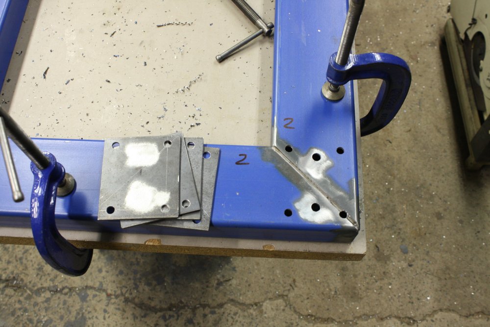
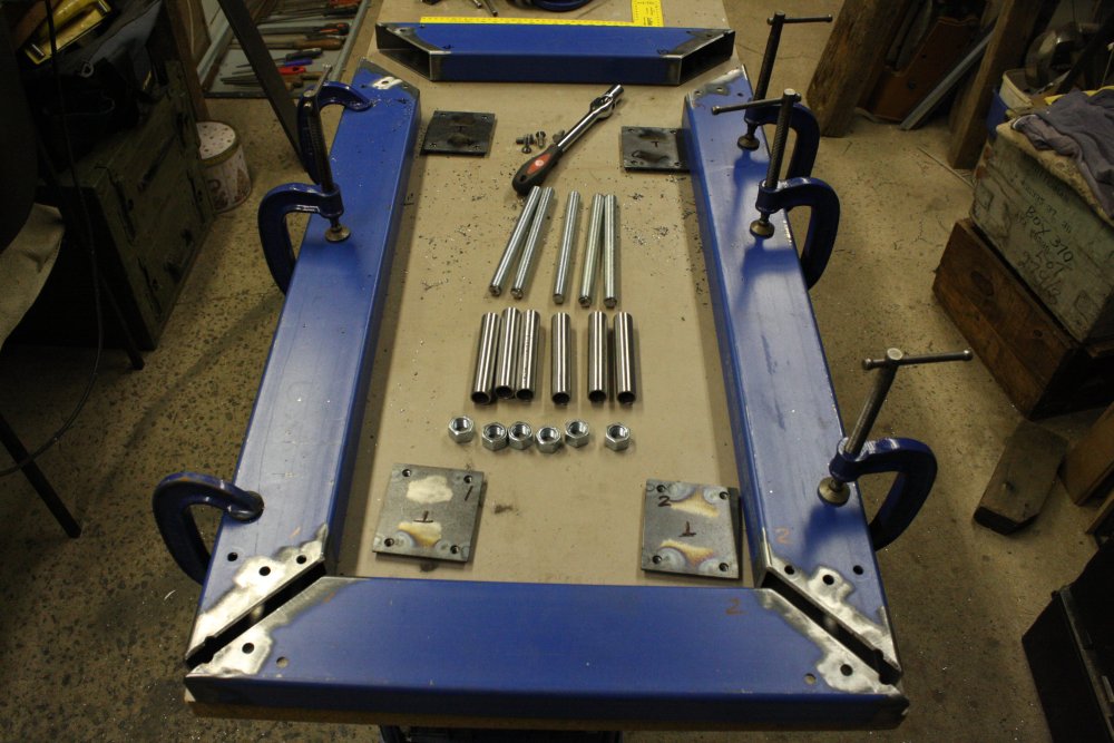
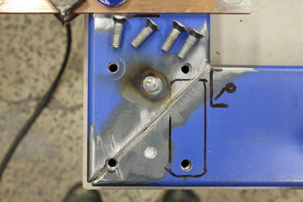
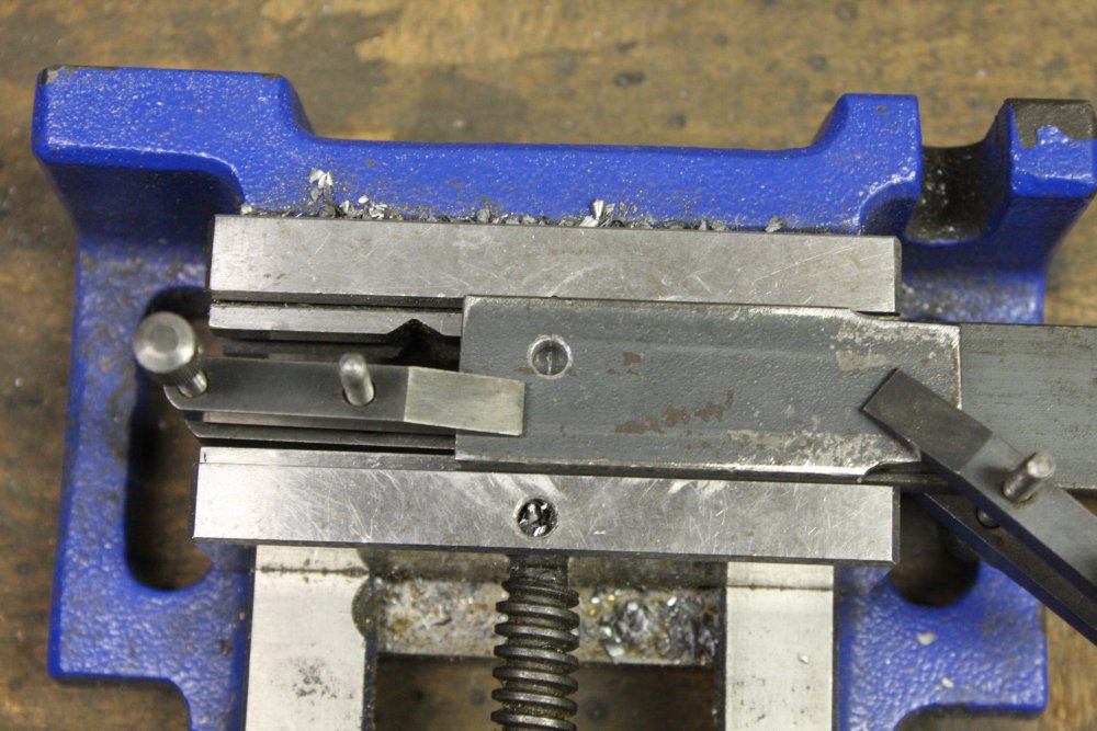
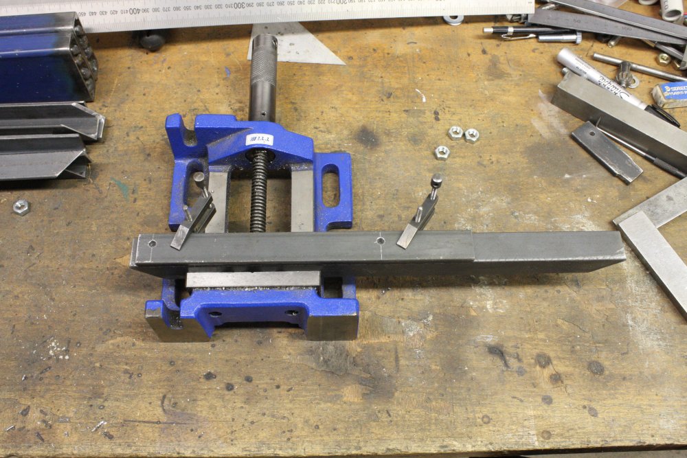
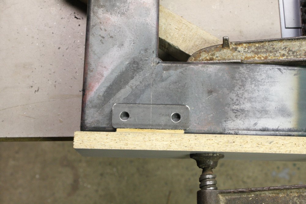
1. The plates that will bear the nuts for castor wheel mountings go inside the base at the corners. Holes need to be drilled, and they must be accurate. Here the base sections are clamped down in the accurate final square positions, and the master template plate being used to transfer-drill holes. Note the holes in the plate are small, not the final size. This is so transfer drilling can use a small drill bit. Easier for hand drilling, and more accurate.
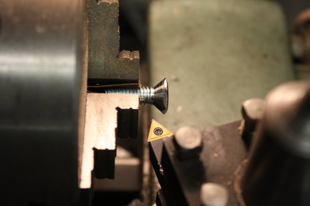
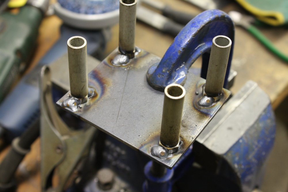
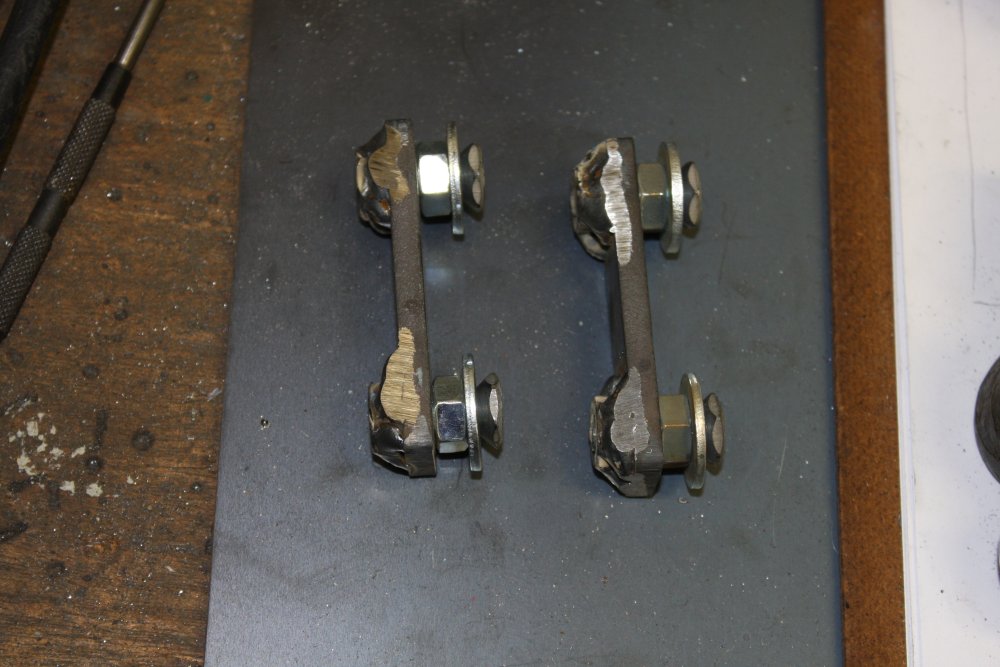
2. Later those plates have to be accurately positioned, for spot-welding in place inside the beam. The bolt holes will be a little oversize for clearance, but the plates must be positioned so that bolts are in the center of those holes. This is how it's done - take standard bolts and machine their heads to countersunk form. Now we have 'centering bolts'.
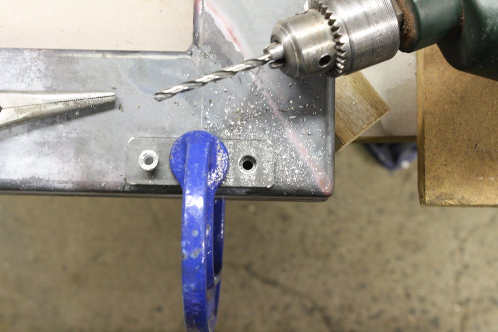
3 - 4. More preparation. Removing coatings where there will be welds.
 |
 |
 |
 |
 |
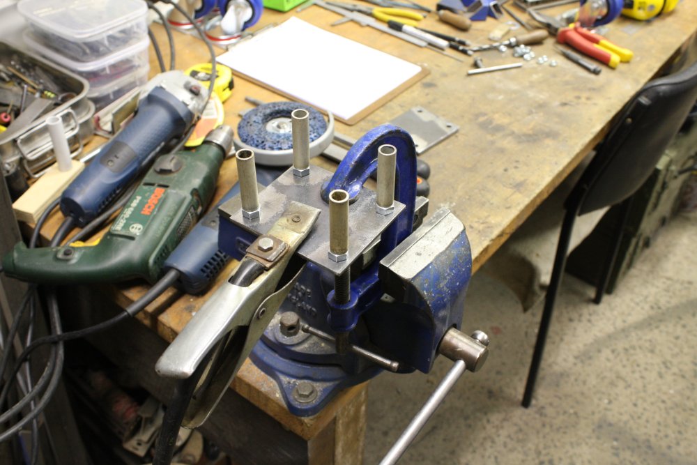
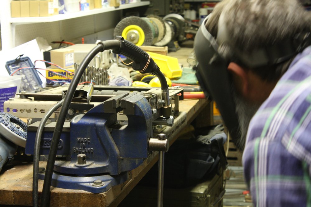
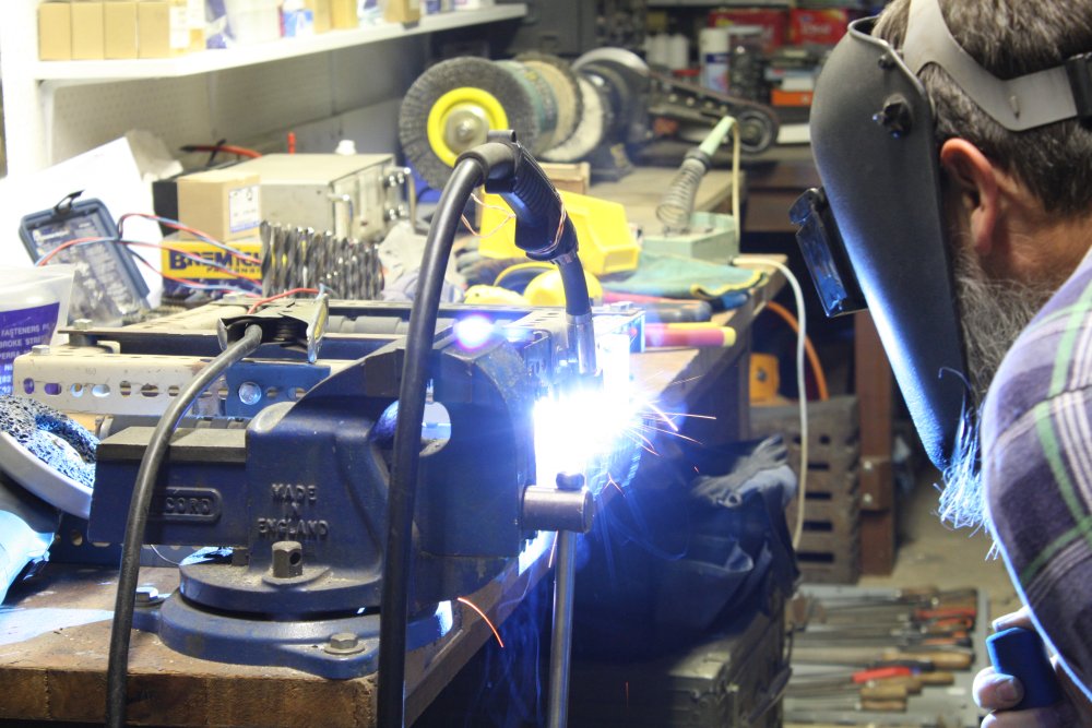
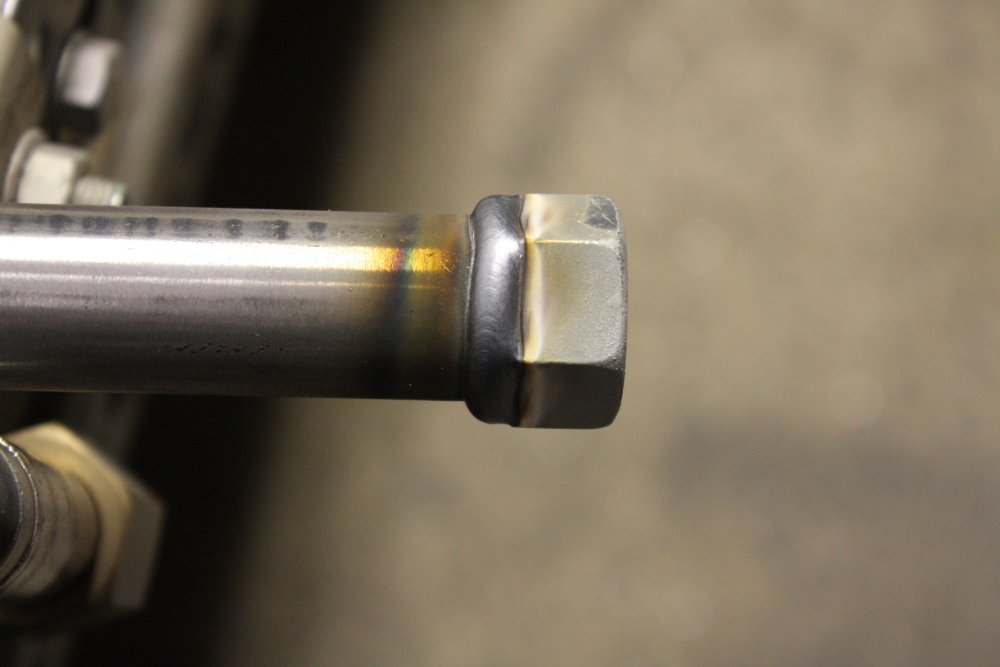
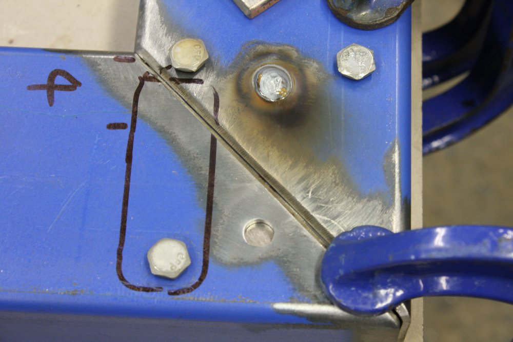
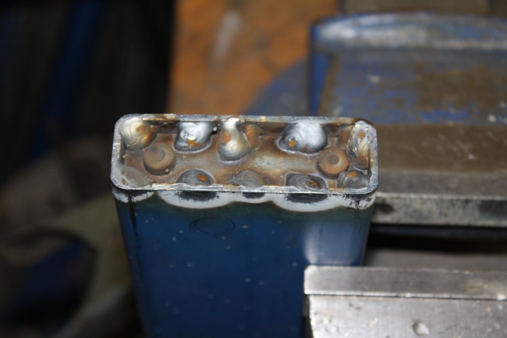
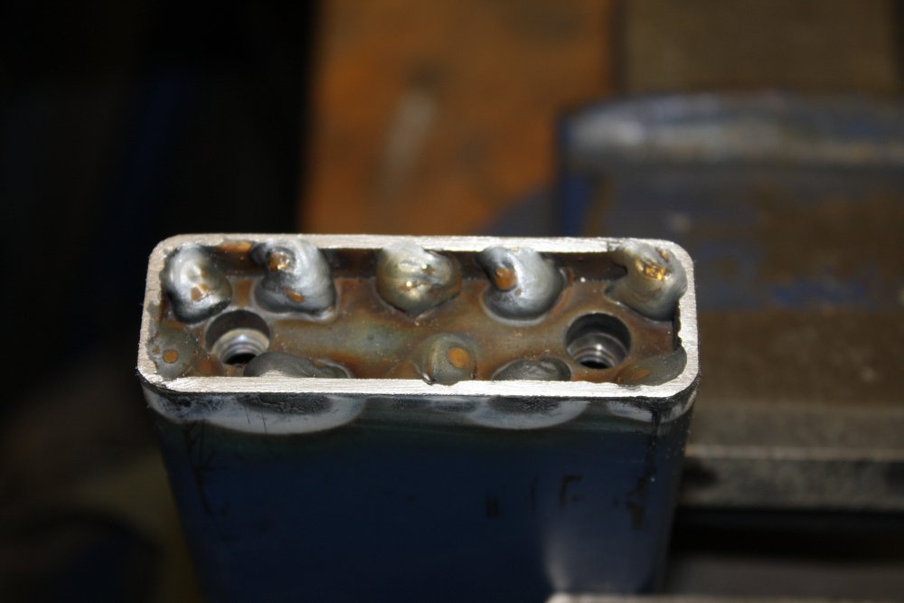
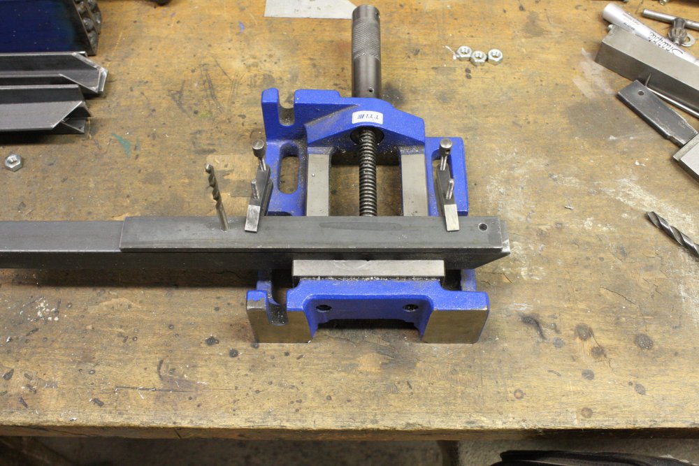
1 - 3. Welding on the nuts. They are held with the centering bolts, and it's important to not get weld spatter on the threads. Once welded on, the threads on these nuts are precious, and unscrewing even tiny weld spatters through them would wreck the threads. So the threads are protected with some small aluminium tubes, just sitting loosely. Welding smallish nuts (5/16" here) is a bit of an art; making sure it's really welded, while not melting the nut right through to the threads. You have to apply most of the arc power to the baseplate, with short flicks onto the nut.
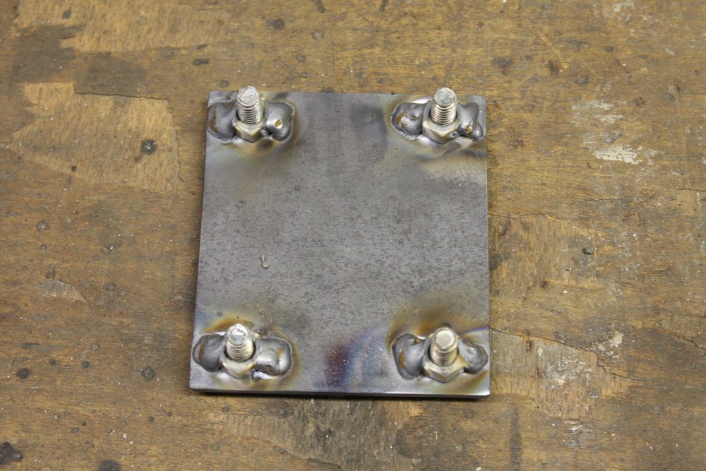
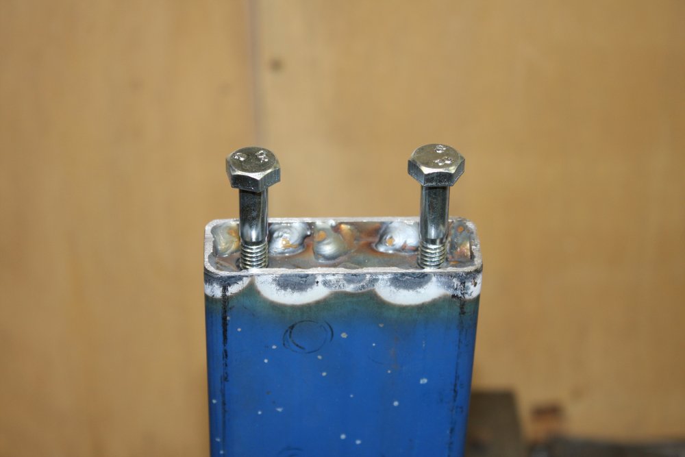
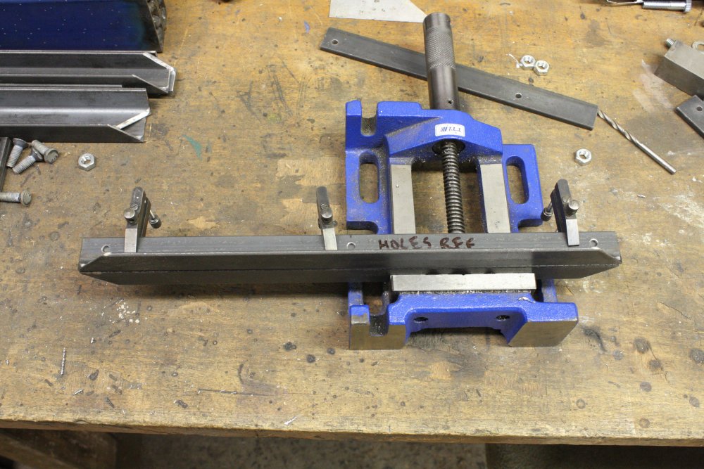
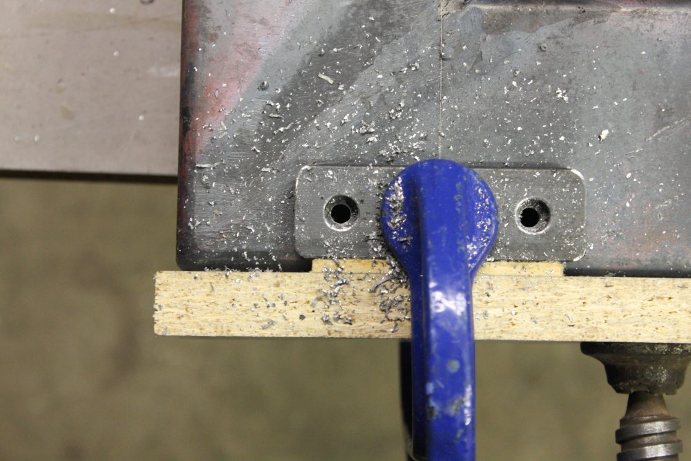
4. Just testing fit, again with the centering bolts. Seems all good. For the holes right on the break line I had to use a bur in a drill to get them right, as drilling up to the final size hadn't been very accurate due to the metal discontinuity.
I can't weld the base parts together yet, as there's more internal work to be done related to the upper stand connections.
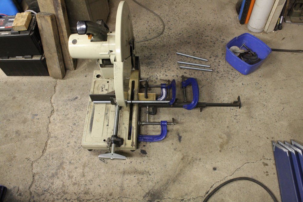
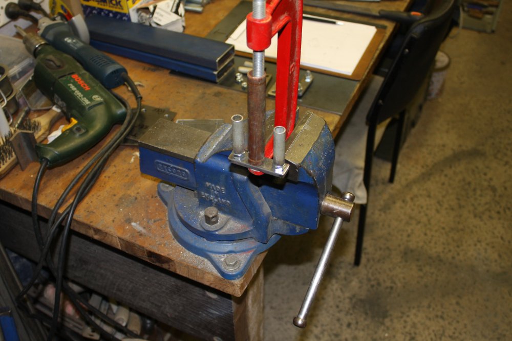
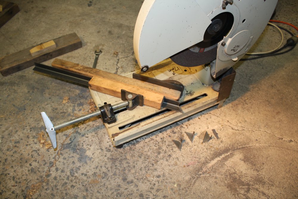
5. Jigged up for cutting the 16mm threaded rod sections for the screw downs.
 |
 |
 |
 |
 |
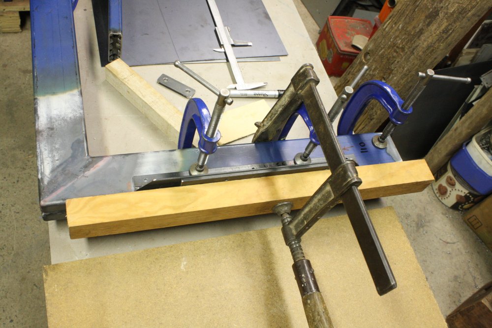
1. For this base I'm going to do all the work for the screw downs while the base is still in sections. For the instrument rack bases I'd done this after the base was one welded unit, and it was a pain because they are heavy and awkward to hold on the drill press platform.
2. Setting up my pipe rotator for welding nuts to the ends of the screw-down tubes.
3. FZZZZZZZZ! My thumb on the button thing controls the welder. You can start anytime, but have to watch it and turn off just as the weld rotates around to its start point.
4 - 5. One completed. Yes, I think the weld is neat too. I wish I could do like that by hand.
 |
 |
 |
 |
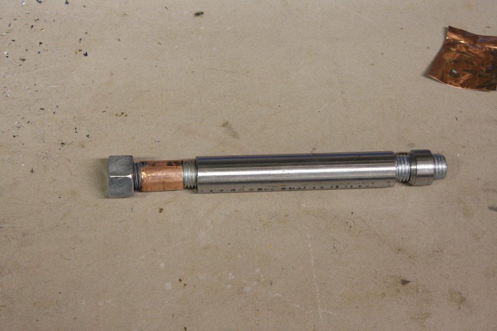
1. How the threaded rod is centered in the pipe for welding. To avoid the thread binding in the nut, it has to have some clearance from the tube. Actually I'd goofed slightly, and forgot to trim the pipe ends exactly square in the lathe first. Result - the rods screw in OK, but are not quite on center at the other end of the tube. Oh well... doesn't matter.
2. All six screw down pipes done.
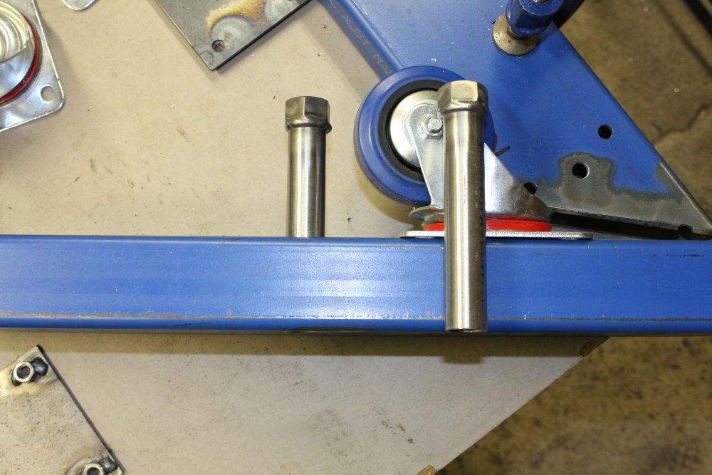
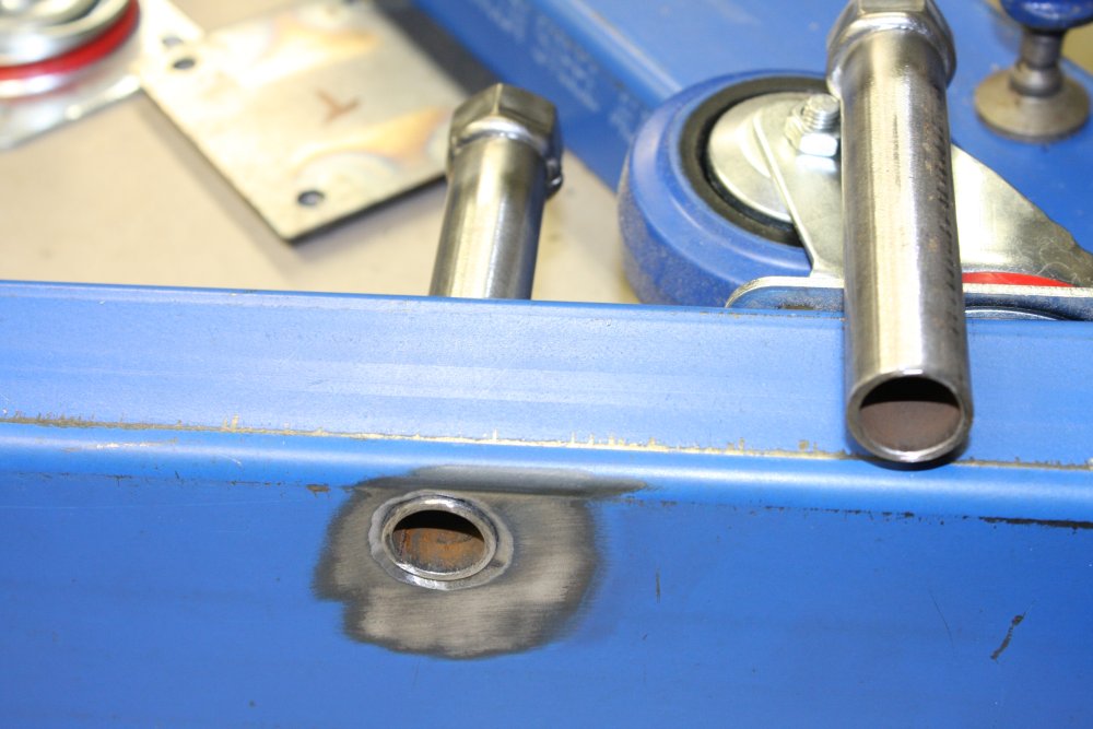
3 - 4. How the screw downs sit relative to the castors. I won't weld them in till later.
 |
 |
 |
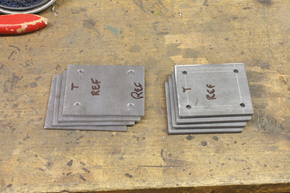 |
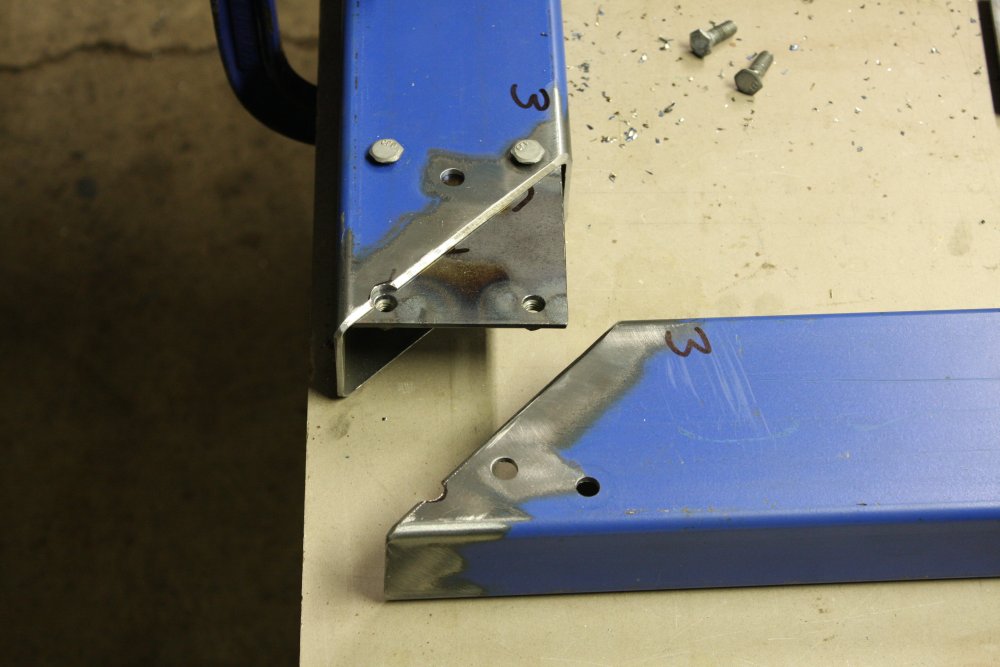
1 - 2. Starting on bits for the upper frame. It will attach to the base in the same way as the castors - plates bolted to the base, via an internal nut-plate. Here I'm cutting the 6mm thick strip for the stand footer plates. It's surprisingly quick and easy.
3. Drilling all the footer plates from the first one as a template. That one made accurately by scoring then punching then drilling small holes. They can be a bit off, so file them till they are on center. Then drill out to a larger size. Check 4 holes are in a square by drawing through them onto paper, then flipping the plate various ways and visually checking the holes match the paper circles. I want the frame parts to fit the base no matter which way round they are assembled.
4. The plates for the internal nuts also drilled from the same template. These are now drilled out to full size. But not the footer plates yet, since they'll be used to drill the holes in the base later.
 |
 |
 |
1 - 3. I realised I could weld the castor plates in at one side of each joint, for ease of assembling the base while working on the upper frame. Felt pen marks are the rough positions of the upper frame struts, which will be on the other side of the base.
By this time I'd changed my mind about how the upper frame would be built. Originally the plan was to have 'end frames' as single welded pieces, then bolted on supports lengthwise under the folding machine. But this required some bracing along the long faces of the structure, and that would obstruct access to the storage space. So I switched the design round, to welded pieces that ran lengthways, and bolted-on braces and machine supports across the narrow dimension. This worked out better for the machine bolt-down points too. Luckily the change meant only the two very short sections I'd already cut were now scrap. They'll be useful for something eventually.
 |
 |
 |
 |
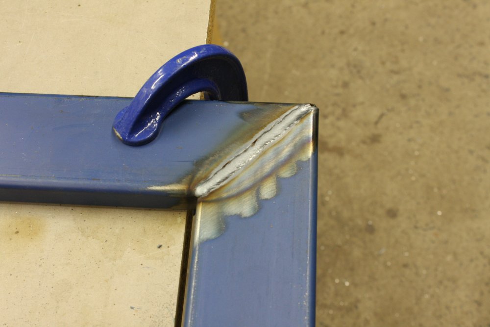
1 - 2. Welding the upper frame. It's constructed of smaller 75 x 25mm section, welded in two identical 'U' shapes. And I can see a potential problem here. I'm certain the corner welds will result in some change from the set up square shape. But how much? This is one area in which my self-taught welding ability is very lacking. I don't know enough to keep metal post-weld contraction under control and predictable. If I knew what would happen with these welds I could compensate by offsetting the initial angle. Or I could do one, then try to get the others right based on how that moved. But that leaves me with one wrong one to fix still. Or multiple ones, out of true by varying amounts if the effects are not consistent. So I decided to do them all the same, then deal with the consequences afterwards. I do know from experience that I can straighten things out via the 'red heat and excessive force' method.
3. How it was jigged up, allowing for flipping it over and doing all welds without removing the clamping bar. I could also put the piece in the bench vise for conveniently welding the inner and outer edge welds.
All corners welded from inner corner to outer, both welds on one side at a time, then the outer edge, then lastly the inner edge fillet.
Previous bases I did were complete rectangles, and they stayed square after welding. Presumably the forces all balanced out.
4. But not these. At least the two pieces warped by the same amount. The inner dimension between the legs became 6mm smaller at the ends of the legs, than at the top. So each leg bent inwards by 3mm at the end. More than I'm prepared to live with.
What's most frustrating is that I do not understand why this happens. It's very consistent on all four joints, so is 'an effect' not some random warping. I understand the weld metal shrinking as it cools. But firstly the bevelled junction prior to welding had the inner faces pressed against each other (so how can it draw inwards at all?), and secondly why does the join contraction in this configuration change the resulting angle?
Oh wait... Maybe I see it now. The weld-melt goes all the way through, so that inner edge below the bevel doesn't remain solid where the melt pool is. So starting at the inner corner, the melt pool leaves a line of full-depth contracting metal, while the as-yet unwelded outer section of weld still has the solid butting edges. Hmm... I think I can see why the result would be a net closing of the corner angle. Maybe... Uh... would this not happen if I left a little gap before welding?
 |
 |
 |
 |
 |
1 - 3. Annnyway... Bring on the heat and force. I've done this before. This time I have four corners to bend back to 90 degrees, and I'd like to see how accurate I can get the process.
The idea is to heat only a small area at one corner, while the rest of the frame is clamped and the one leg can be forcefully pulled outwards (or inwards.) As well there needs to be a convenient, stable scale, to judge results.
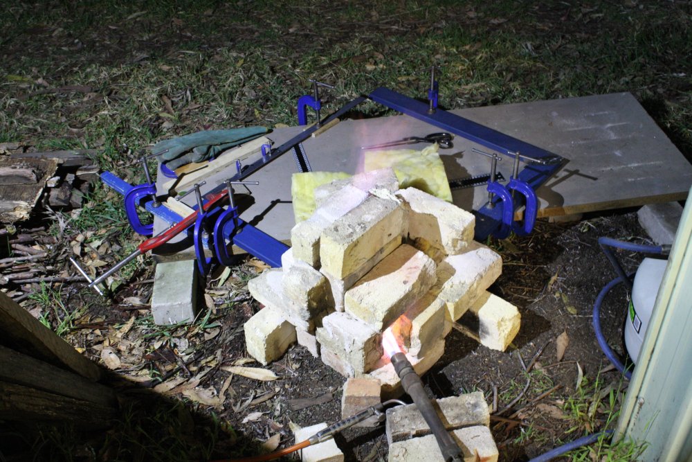
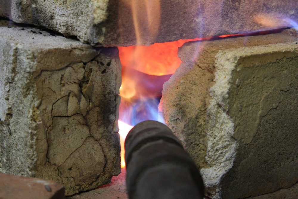
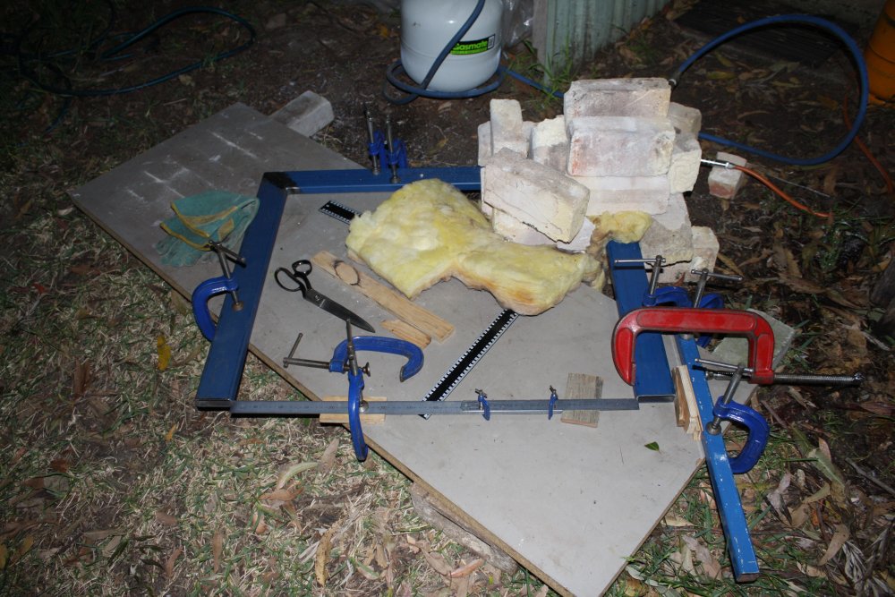
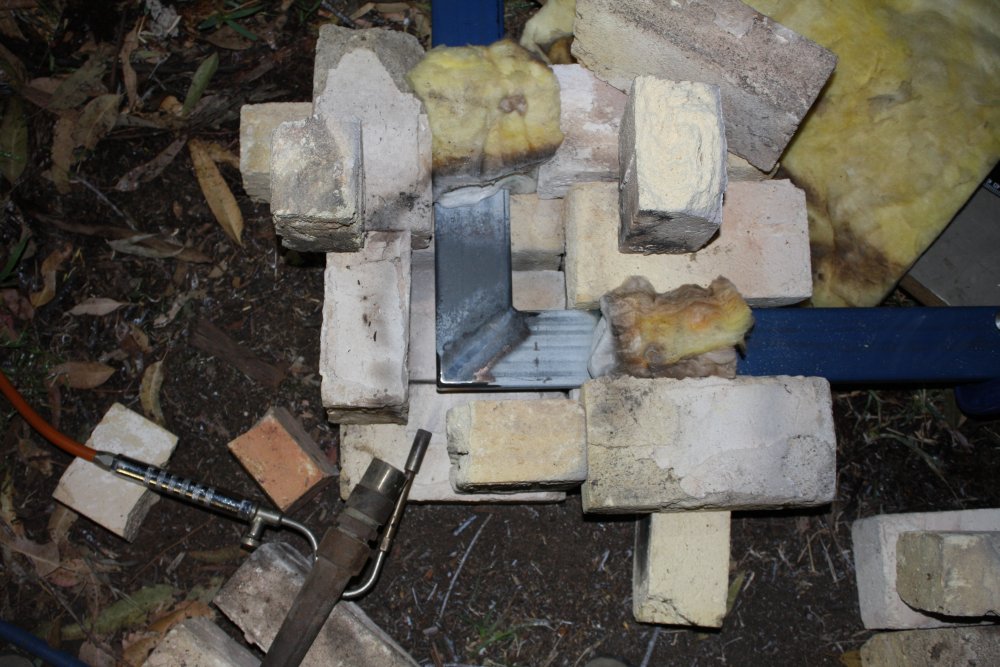
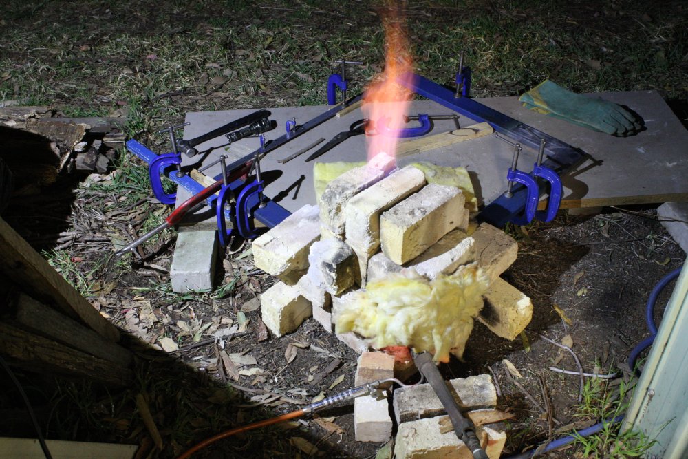
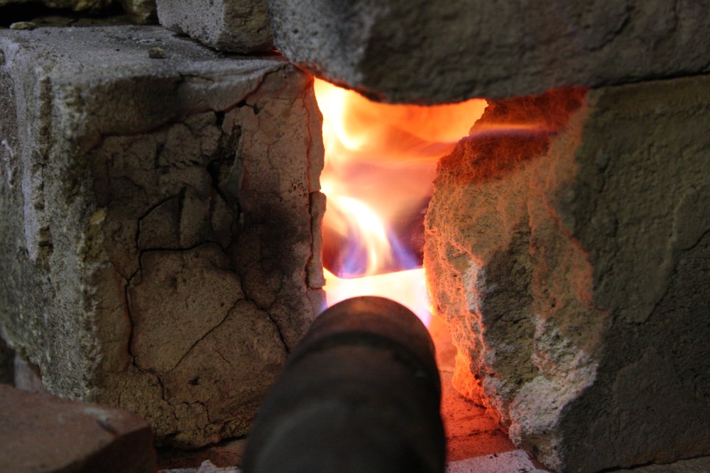
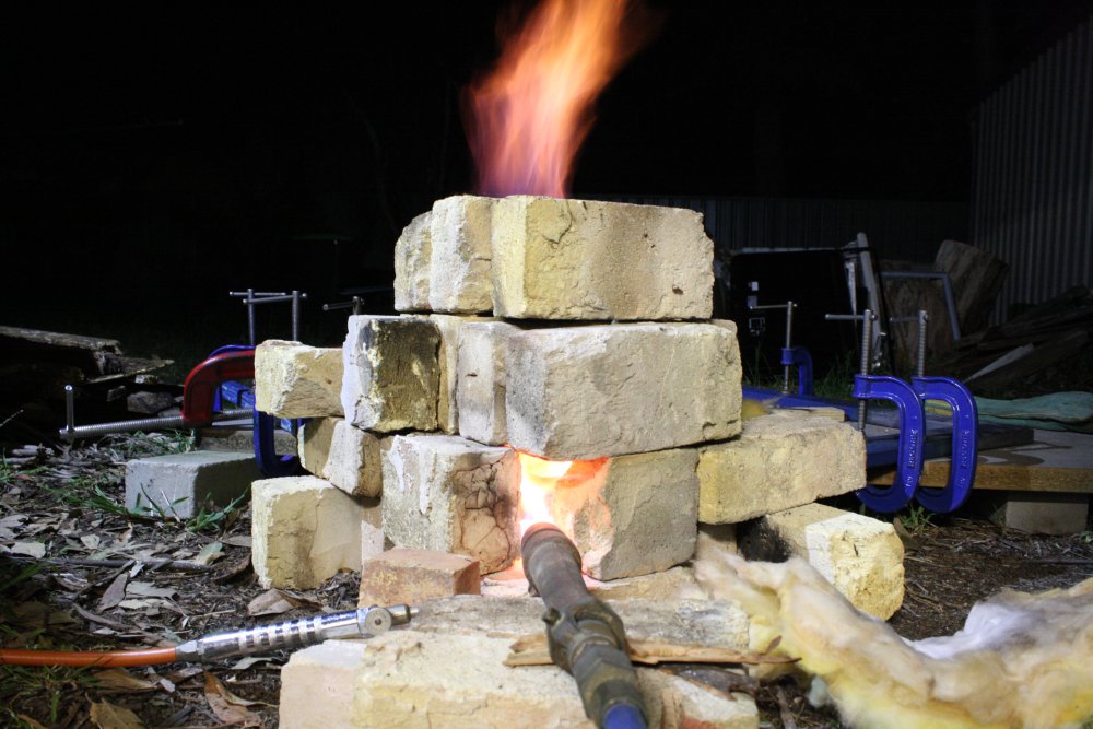
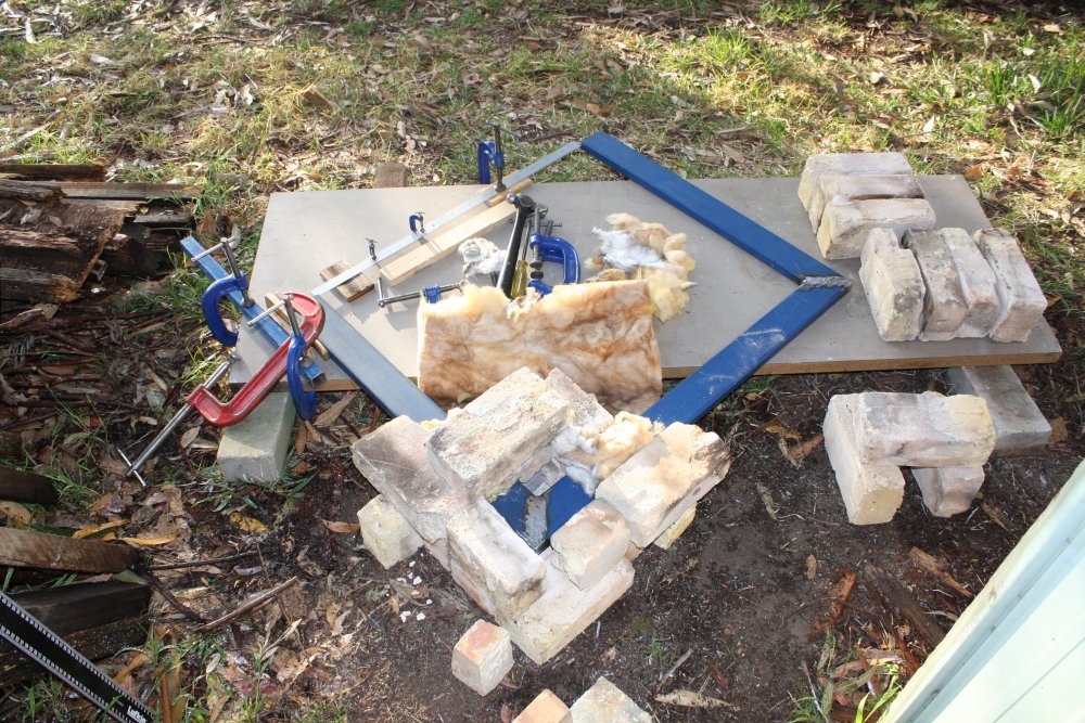
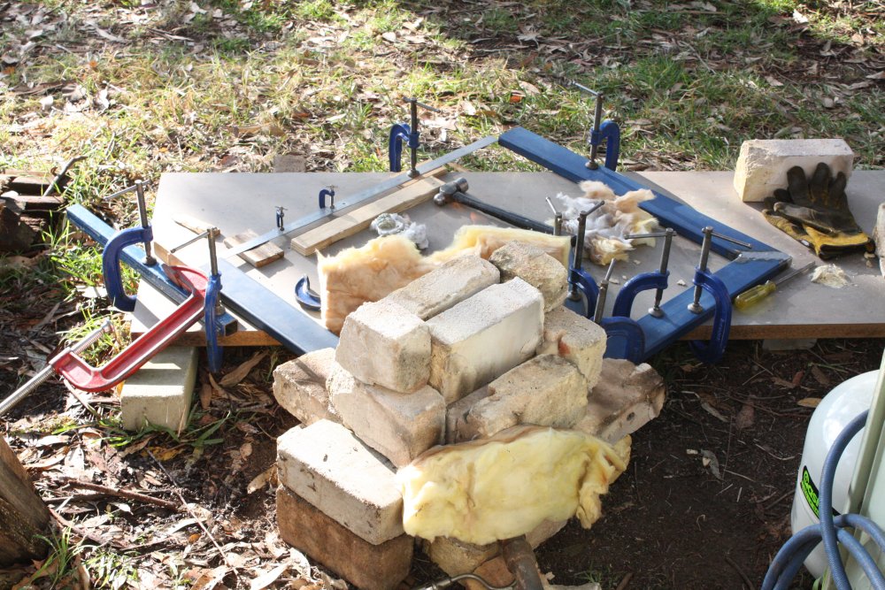
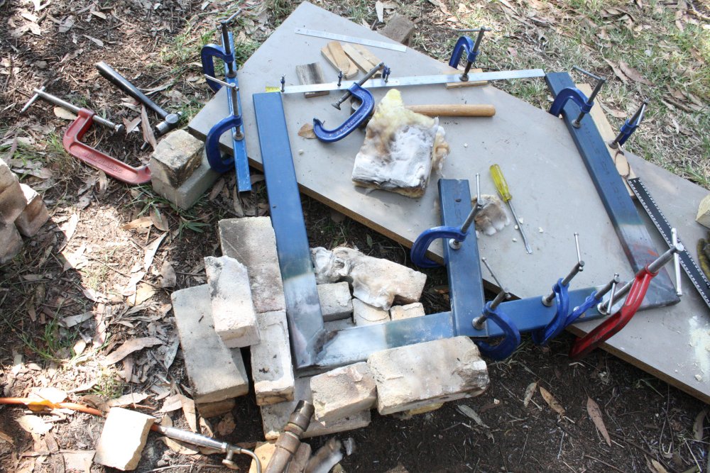
This is the arrangement I tried. Custom furnace enclosure made of firebricks, and a couple of propane torches. Random flame sealing using ordinary house insulation glass wool. It melts at these temperatures, but slowly enough to be usable for firings lasting half an hour.
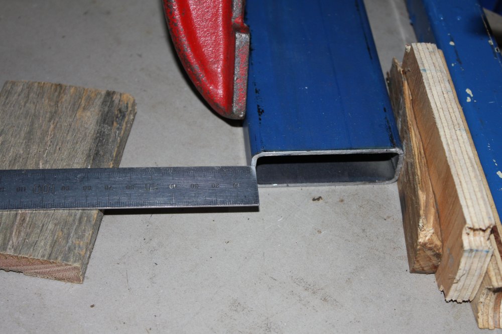
The two steel rulers are clamped together to give a length reference that is the exact size of the correct spacing between the frame legs (ie at the top, next to the cross bar.)
One thing about this system of improvised furnace and big propane torches, is that it's highly preferable to do it outside, at night. For one thing it's hot work, and secondly the potentially large flames can barely be seen in daylight. Easy to set yourself or surroundings on fire, when you can't see the flames and a fraction of a turn on the gas valve goes from small flame to meter high wall of flame. And so these pics are night shots, with a spotlight and some with flash.
4. For the first attempt, I initially clamped the victim leg to be where it should be: 3mm less than ideal, since that's how much the other side leg is wrong. This totally didn't work. After a cycle of taking the joint up to cherry red then cooling, when I unclamped the leg it was about the same as before. I'd had a feeling that would be the case. The red hot steel still holds it's shape memory. To change it, it has to be disrupted by bending past the point where you want it. Also, there should be shocks, to lock in the new shape. And some hand waving, to make it look like I know what I'm talking about.
5. Opening the structure after first firing. The paint is of course gone. The gray colour is iron oxide scale, that is easily cleaned off but does no harm to leave for now. With later builds I reduced the length of beam that was brought to red heat.
 |
 |
 |
 |
 |
1. After cooling and unclamping that first attempt. Maybe 1mm of improvement. Fail.
2 - 4. Later runs. With all these I was being very cautious, trying slowly increasing amounts of forced distortion. By the time of this picture I'd got the first corner about right (still slighty under) and now was doing the 2nd corner. Something quite surprising I'd found, was that if the leg was left free to move as the corner was heated, the end moved outwards a lot. Then as the joint cooled it would move back to it's original position. This is totally mystifying. It seems like the corner is being heated fairly evenly, and the expansion/contraction should be even. Why does the angle change?
But anyway, it's consistent. So if I want to change the angle by 3mm (at the tip) then I just note the position once it's hot and stopped moving, force it out till it returns when released to a position 3mm greater, then let it cool. During which it pulls in again, but to the desired end result. Fine, but it pisses me off when I don't really understand why something is working.
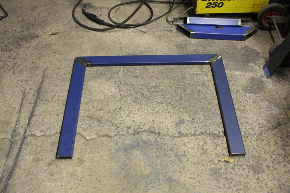
5. Final size of the frame piece I'd started on. It's still 2mm undersize, but the frame has enough spring that it can easily be pulled out to the correct position by hand. Good enough. It was getting late, my flu was really bad, and I wanted to go to bed.
 |
 |
 |
 |
 |
Too sick the next day to do anything. The day later on the 16th I got up early, feeling not nearly as bad. Decided to do the second frame furnace proceedure in early morning daylight, despite the invisible flames.
1. Setting up.
2. The total error before starting. 6mm, ie 3mm per leg. I checked the corners with a square, and the error was shared equally between them.
3. First firing well underway. Yes, there's a big flame coming out the top of the furnace, and yes that's about how visible it is to the eye. Mostly you can only see it by the shimmering of things behind it. I'd left the leg unclamped, and same as with the other stand as the corner heated up the leg end moved outwards about 8mm. I still don't understand...
4. But never mind. By now I had a good instinct for how much to force them outwards to achieve the desired change. After doing both corners and letting it cool, this is the end result. Dead on. There's a very slight inequality in the corners, by about 0.5mm each one at the leg ends. Sum result is zero error.
5. Opened up after the last firing.
 |
 |
 |
 |
 |
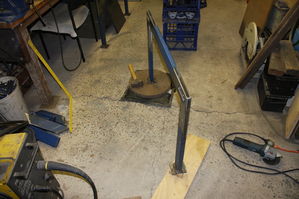
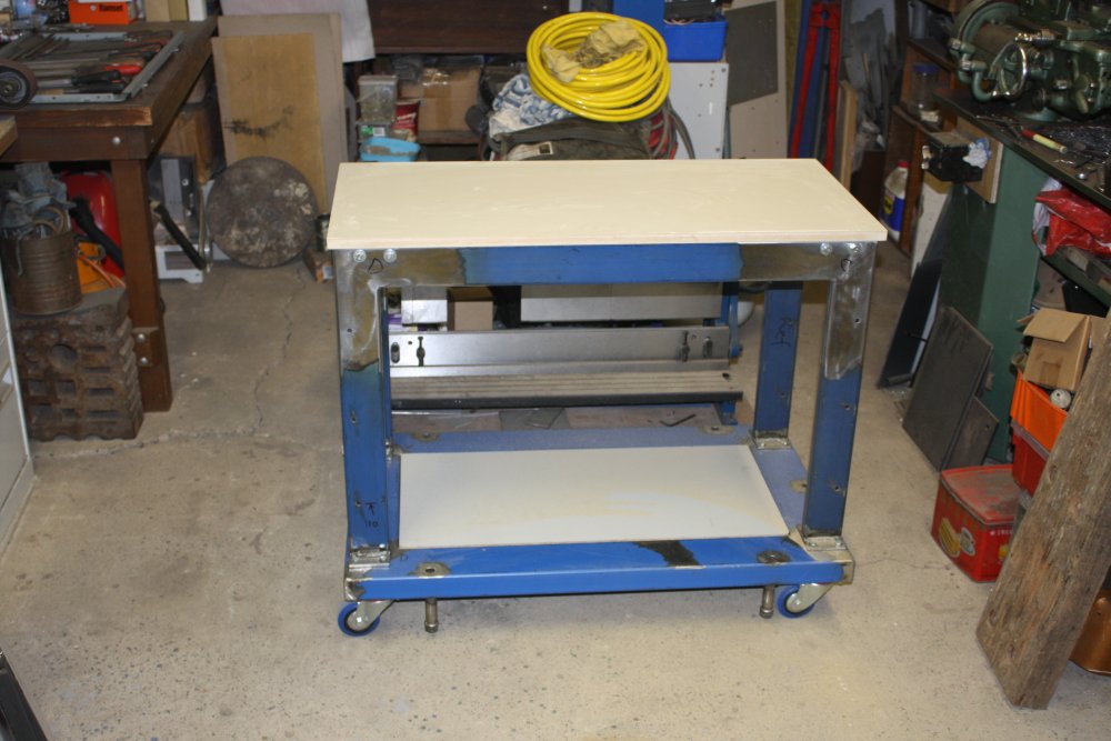
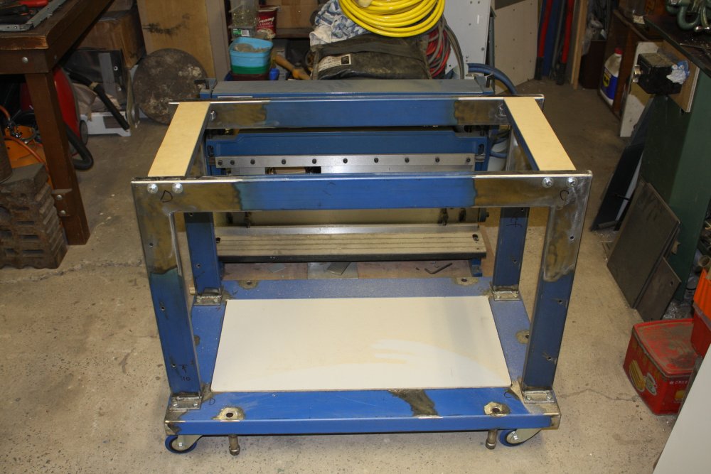
1. When originally working out the total height, I'd been generous. Now I can bolt and cobble the major parts of the frame together and actually look at it. Thinking about working with the machine on top (including tape measuring to key points), I've decided it would be better if it was a bit lower. I could pick a number, or... I could make the upper platform surface on which the folder will sit, the same height as all the other benches. More for appearance, but the end result is about where I'd like the machine anyway.
2. How much to remove? This much. 150mm. The original stand legs were 750, so shortened they are 600 high. Considering these numbers came from physically measuring against an old bench, plus the 6mm foot plate and 20mm for a top board, that round number is something of a fluke too.
The 2mm warp error in one of the two pieces was still bugging me, so the next day before cutting the legs shorter I set up the furnace-bender again, and fixed it. Practice makes perfect, I got the cooled-down size spot on first try.
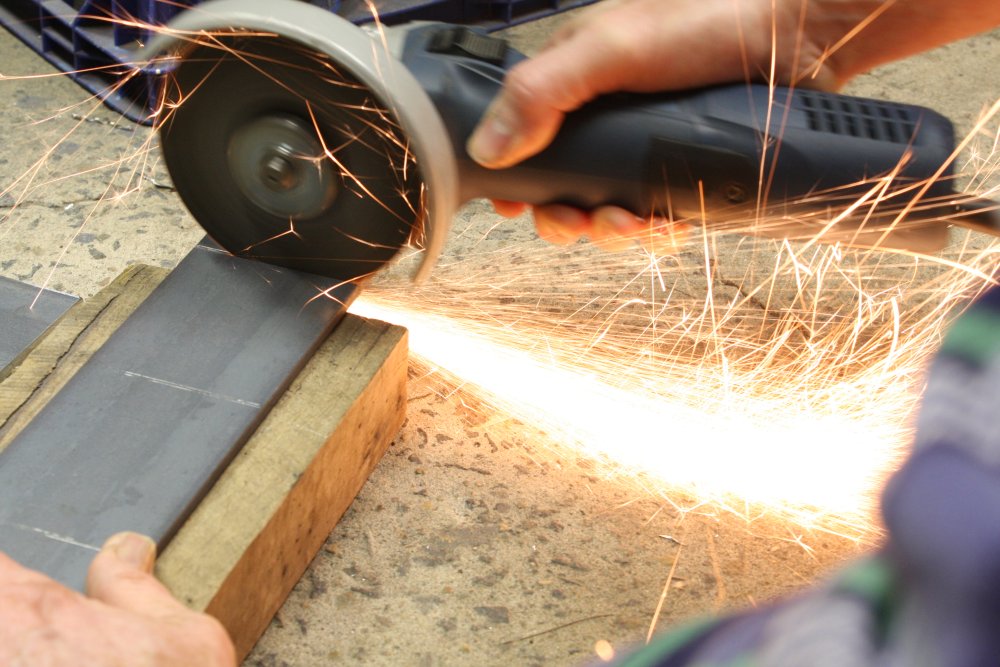
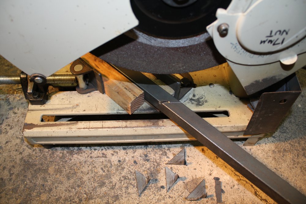
3. Then the cutting. That old comedy sketch comes to mind (Laurel and Hardy?) of a bloke lowering a table by sawing bits off the legs. But he could never get them even, and so kept on sawing off bits till there was nothing left. I took special care to get these cuts very precise. With the lines scribed, the piece is lined up in the abrasive cutter then clamped. Rather than just plough into the cut, when I want to be certain of accuracy I lower the running cutting disk gently and let it just touch. Them lift it and check the edge of the actual cut is right on the scribe line.
4. Next comes welding on the footer plates. Plenty of potential for wrong alignment here! Since I want the frames interchangeable I'm making a welding jig for these. First step is a solid base on which the footer plates will be bolted down for welding. (It's cut from an old hardwood fence post, dragged out of the firewood heap for this duty. This one is amazingly straight and square. It will go back to the woodheap later.) The base will ensure the plates are identically spaced, squared up, and in the same plane. I'm hoping the bolts will be enough to stop the plates becoming bowed by the welding, but not confident of this. Maybe more 'heat and force' required afterwards.
5. Getting the frame upright and perpendicular to the footer plates. The whole jig can be removed from the 'bench' and tilted for easier fillet welding of the footer plates.
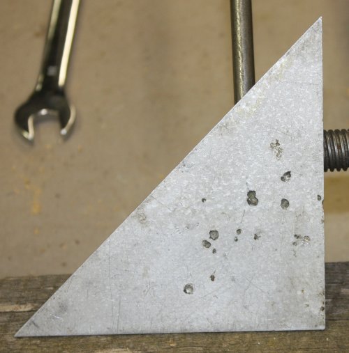 An aside: Lately I've been gathering together a few things I made as a small child, for a 'beginnings' post here. While setting up this jig I realised I was holding one of those ancient artefacts, that I'd forgotten about. Sometime earlier than age 10 I made myself this small 45° setsquare. I had plastic ones, but not a small, robust one for metalworking. It was just cut from a piece of scrap aluminium I'd found, then the edges filed straight and to correct angles.
Maybe a year later I was playing with charging up a big electrolytic capacitor and vaporizing bits of wire and metal by shorting them across the terminals. Yeah, as a child 'electric things that went bang' were fascinating. At one point for some reason I thought it would be fun to use my metal setsquare to short the cap. Hence the burned pits in the metal. When I accidentally let one edge be the contact point and took a chunk out of it, I realised this had been a silly idea. Kids...
Anyway, it's been a useful tool my whole life. I guess it's the earliest thing I made that I still use.
Whoah! Oh, that was close.
After setting up that jig to weld on the footer plates, yesterday I was mostly busy with some other stuff. I could have done the quick welds, but dithered, and then decided to leave it till tomorrow.This morning while getting up I realised - wait, I can't weld those on yet. Because I still have to drill the holes in the frames for bolting on the cross members and bracing panels. To get those matching I have to be able to clamp the frames flat together while drilling. But once the footer plates are attached, the frames can't be clamped together. Ouch, glad I didn't go ahead and weld yesterday. Hesitation Man to the rescue! Uses power of delay!
In fact I realised that to get the cross connections holes right, it would be best to make all the extra members, and use them as drill templates. So, that big jig gets put aside for the moment.
 |
 |
 |
 |
 |
1. I'd hoped to make the end brace panels from scrap. But didn't have quite enough L section. Another trip to the steel supplier, so might as well buy clean 1.6mm sheet while there. Here I've cut up the sheet to the two 380mm square pieces. To cut a long straight line with the angle grinder, I clamp a bit of scrap wood along the scribed line. The wood resists light sideways pressure of the cutting wheel for long enough to get the cut started.
2. Squaring up the two top horizontal cross pieces. The metal folder will mount on these.
3. The ends will have recessed bolt plates. Here starting to make those.
4. Getting ready to weld the bolt plate nuts on. I didn't show them before, but for this construction I've been doing detail drawings as I go.
5. Nut welding. Holding the plate in an old G-clamp that has no foot-plate at the end of the screw shaft. A small piece of copper pipe around the screw shaft to protect the threads. The welder ground clamp just fixed to the bench vice.
 |
 |
 |
 |
 |
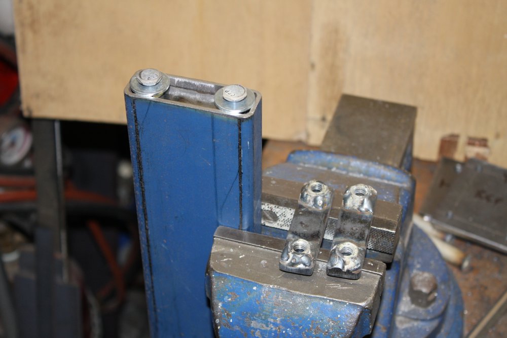
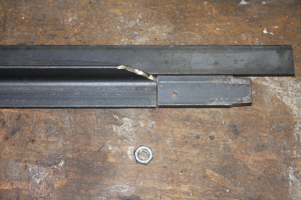
1. End inserts with welded nuts, and spacers to set insert depth.
2 - 3. Like this. The inserts are a press fit. Well actually, a 'hammer it in hard' fit. But that's good. Less likely to move as I start welding it. There's enough room in the middle for some tack welds.
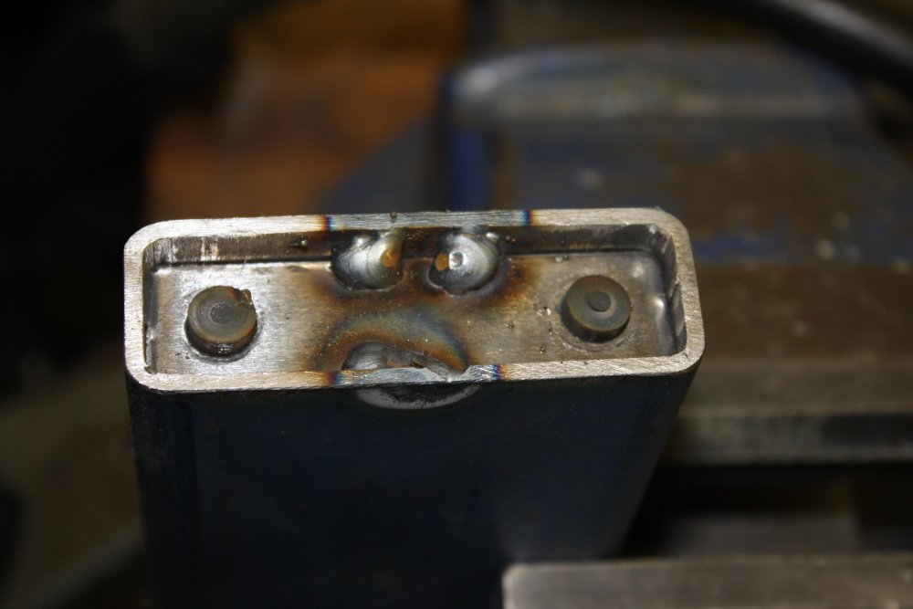
4. After tack welding, the spacers are removed and the bolt holes plugged with a couple of little carbon pieces I'd turned in the lathe. They can't stick up much, or I wouldn't be able to weld into the corners around the holes.
5. It's an awkward weld. The insert piece is 6mm thick, while the tube walls are only 1.5mm. So it's tricky to simultaneously get enough heat to melt into the insert piece, while not melting completely through the thin tube wall. Hence the series of small blob welds.
 |
 |
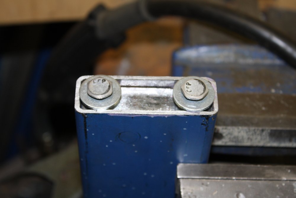
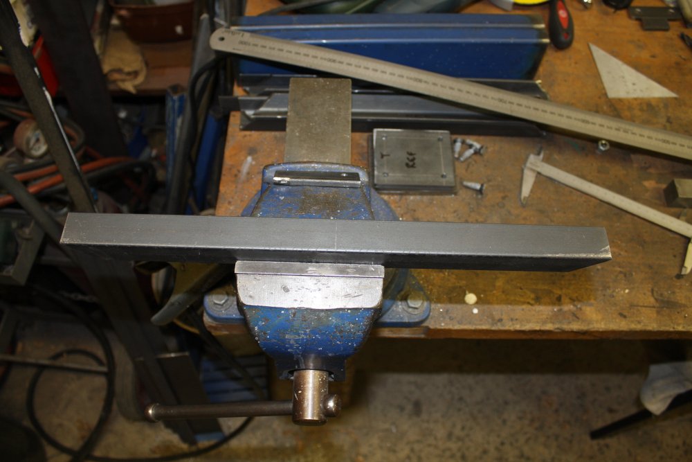
1. With the plugs removed and end face cleaned up.
2. Couple of bolts for show. Except... It turns out these are going to have to be 2" bolts, not the one and three quarters inch ones I have in stock. Another trip to the shops tomorrow. It's funny — I chose to use 5/16" BSW nuts and bolts throughout this thing, because I prefer metric but wanted to use up some of my stock of inch size stuff. Now I've ended up buying more of them - almost as much more as I used from my stock. Bah.
 |
 |
 |
 |
 |
1 - 5. Cutting and beveling the L-angle flanges for the end panels. Are you finding this tedious yet? I certainly was.
 |
 |
 |
 |
 |
Now here's a problem. There will be three bolt-holes on L & R sides of these panels. Ideally the panels would be interchangeable. This means the holes on all four sides have to be identically spaced.
How to do that? Like this:
1. Nuts placed roughly where the holes should be.
2. A bit of scrap steel drilled to use as a spacing guide from the flat of the L.
3. Mark the centerline of one of the side pieces.
4 - 5. Using the offset guide piece, drill another bit of scrap as a two holes separation guide.
 |
 |
 |
 |
1. Lining one of the holes up with the centerline scribe, drill a center and end hole.
2. Now pin the separation guide piece to the center hole, and drill the hole at the other end.
3. Then use that first side piece as a template to drill the holes in all the other side pieces.
4. Finally use the edge piece as a drill template for the frame legs (only drill top surface of four!)
 |
 |
 |
 |
 |
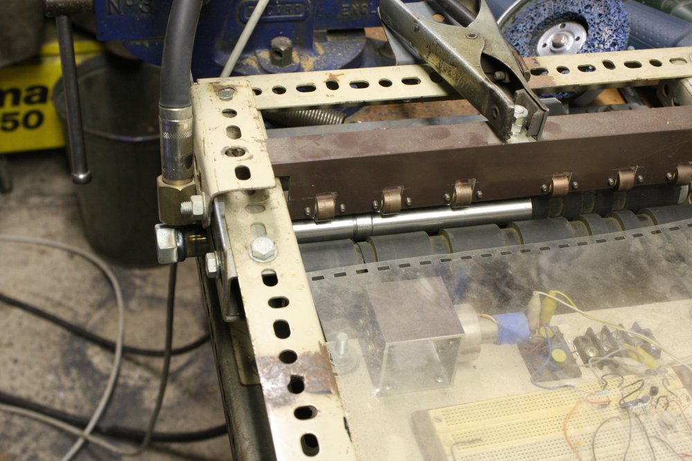
1. Drilling the guide holes in the frame for the two top crosspieces. The drill guide is the same shape as the outside surface of the crosspieces. To get the entire end bearing on the flat of the beam, this has to be spaced down 3mm.
2. Too bad it has the full clearance holes. These have to be drilled by hand, so a small drill bit is better. The solution to centering the holes is to use a drill spacer (whipped up quickly on the lathe.)
3. The result. Both are centered, the right hand one only looks off due to camera parallax.
4. Both sides clamped together, with the upper of four faces drilled with all holes. Using the drill press, these holes will be taken through the remaining faces.
5. Due to the awkward shape and weight, and the need to keep the work accurately perpendicular to the drill axis, a stand has to be improvised. It needs to be exactly in the same plane as the drill stand table. But it doesn't need to be neat!
 |
 |
 |
 |
 |
1. Transfer drilling the holes.
2. Finally, cleaning off the oxide scale from the furnace treatments.
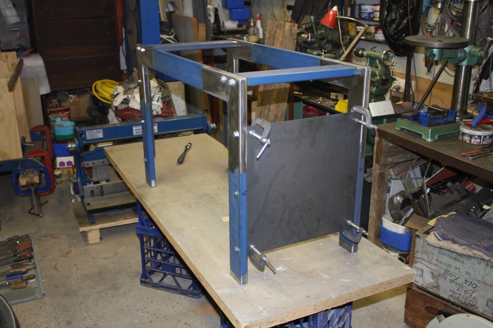
3. Test placement of the top cross-pieces and one of the end face brace panels. Nice to see the thing taking shape.
4 - 5. Time to add the support stops for the top pieces. I didn't want the bolts to be taking the machine weight, since they only bear on the relatively thin walls of the stand sections.
 |
 |
 |
1. Since the side pieces now have all their holes, finally I get to use that jig I made before, to weld on the footing pads.
2. Of course the welds did bow the pad plates a little. But they are small and thin enough that a few good blows with a mallet sorts them out.
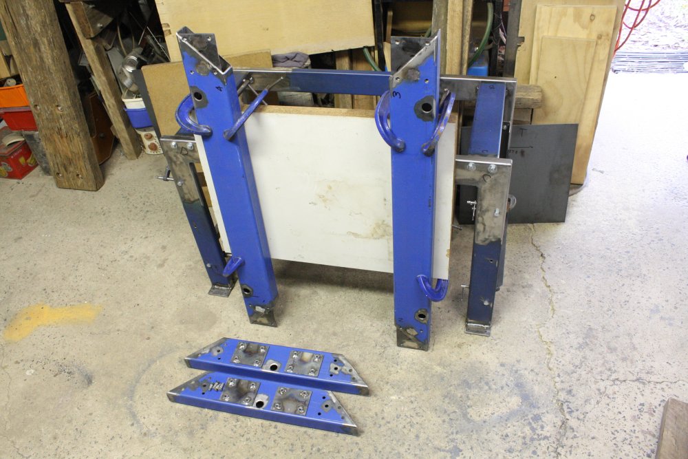
3. So, that's about what it will look like. Here getting ready to mark and drill the holes in the base for the stand footpads.
 |
 |
 |
 |
1. Of course the stand footpads have to bolt into something. So, more nut-plates. And taking the base apart to insert them.
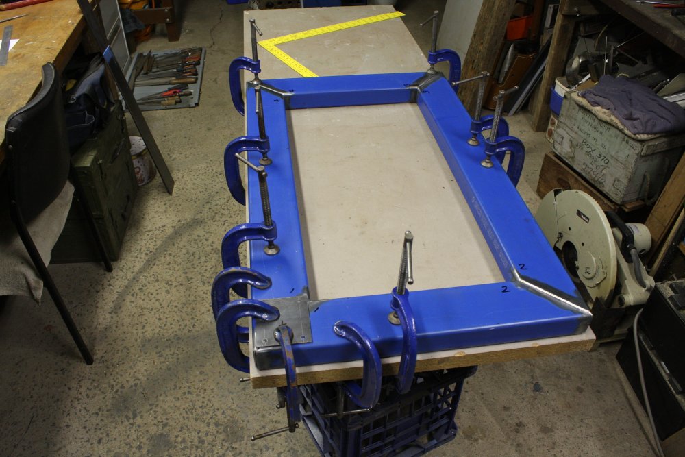
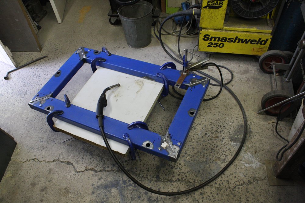
2. While dismantling the base I wanted to be absolutely sure of being able to reassemble (and weld) it in exactly the same shape as I put it originally. Hence clamping the base long edge pieces to this big slab of very thick chipboard, before I'd touched the bolts holding the base together prior to welding it..
3. Ready to weld the base. This makes me nervous, as I don't know how I'd straighten this if it warps or bows due to welding contraction.
4. Ah well, nervous or not, just do it. Not like I have a choice.
It turned out OK. As usual my welding leaves much to be desired, but the frame stayed square.
 |
 |
 |
 |
 |
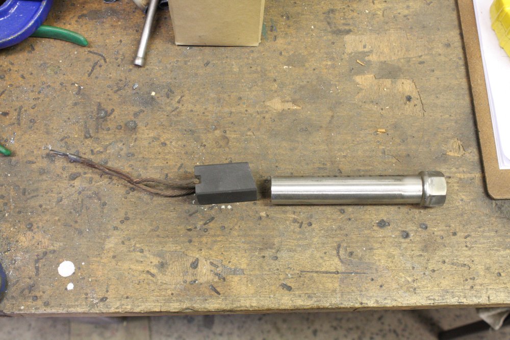
1. Now's the time to weld in the screw-down tubes. To do which I need an arc-resistant plug for the top ends, so weld metal doesn't get into the tube interior. But I don't have any carbon rod large enough for these tubes. Looks like this big old carbon brush from a some large motor will have to be sacrificed.
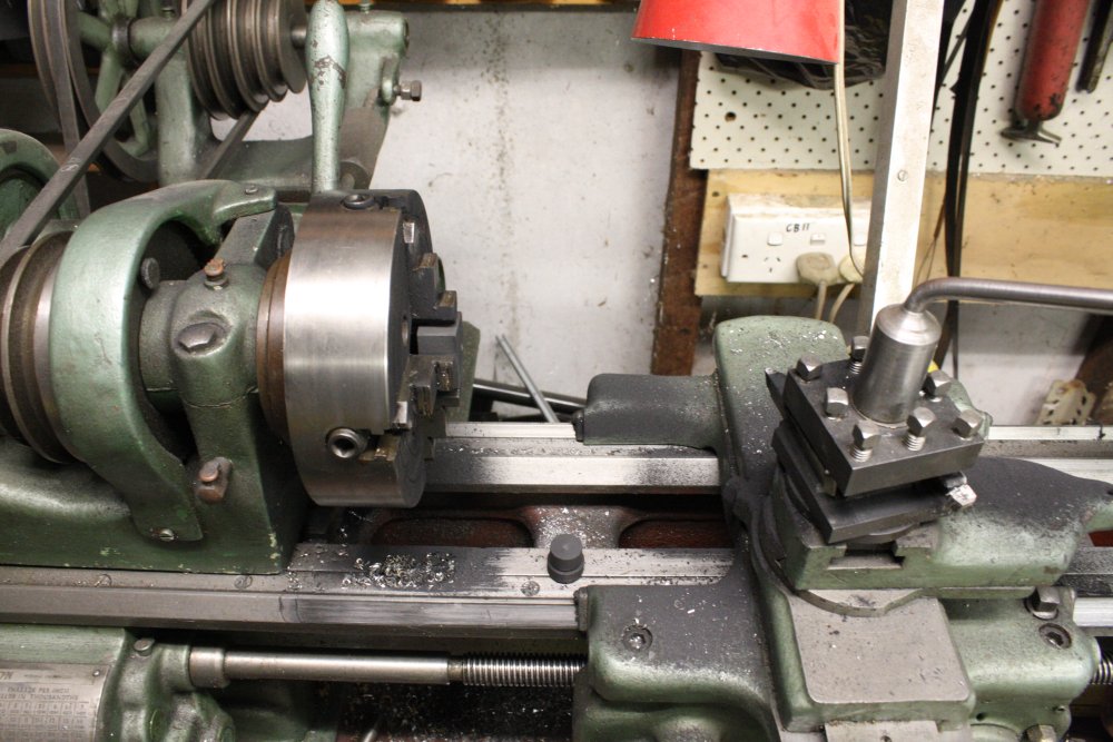
2. It cuts easily in the lathe, but sure makes a mess.
3 - 4. A hard to photograph 'very black thing'.
5. Tubes all welded in too.
 |
 |
 |
 |
 |
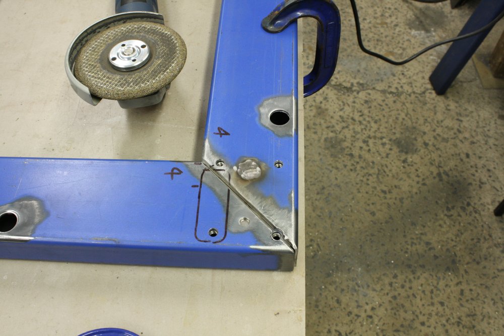
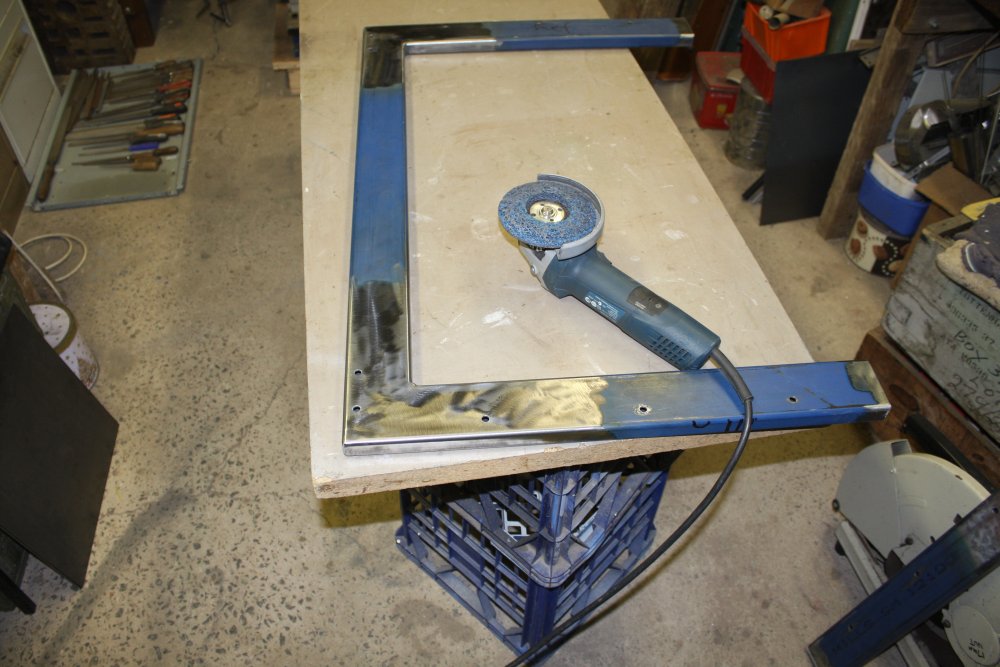
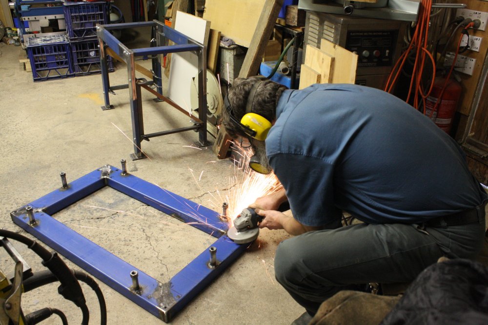
1 - 2. Lots and lots of grinding. Weld beads on all the corner joints and the screw-down top ends have to be flush with the surface. That's why all that bevelling was essential.
3. A critical test stage. Does the upright frame bolt on and stay square? Actually this went very well. All the holes line up, bolts went in easily, and the frame is easy to make square.
4. With the frame square, I can use it as a jig to weld the end brace plates together. Here clamping prior to welding.
5. 'Spot welds' done. Actually filling in a drill hole through the plate with weld metal, attaching the plate to the angle iron behind it. The aim is to achieve the minimum amount of weld bead buildup, since...
 |
 |
 |
 |
 |
1. All those lumps need to be ground flat. It's a lot of work, so I settled down comfortably to the chore. The grinder cuts faster with the wheel edge than the face, so although it takes finer control and concentration (to avoid accidentally cutting grooves in the surface) I did most of the grinding that way. Then finished off with the flat face for better surface finish. Leather jacket over my knees, so I can ignore the sparks jet without setting my pants on fire.
2. Marking up the thick chipboard base insert prior to cutting.
3 - 5. Preparing and welding the supports for the base insert.
 |
 |
 |
 |
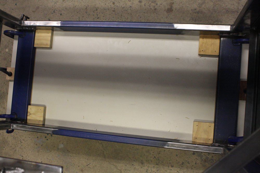 |
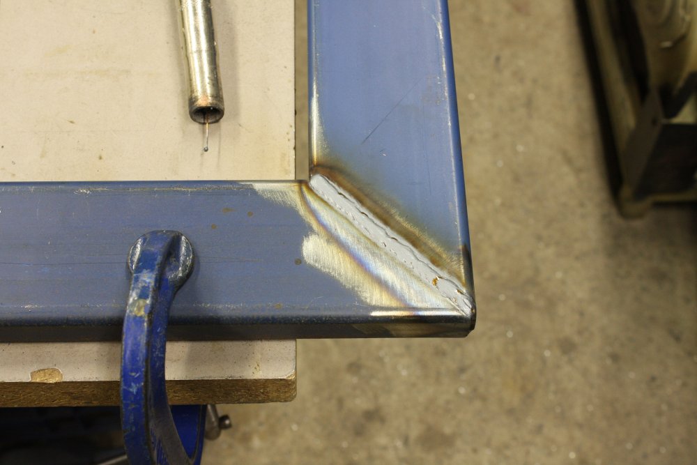
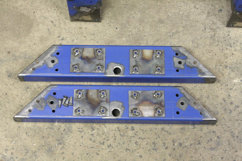
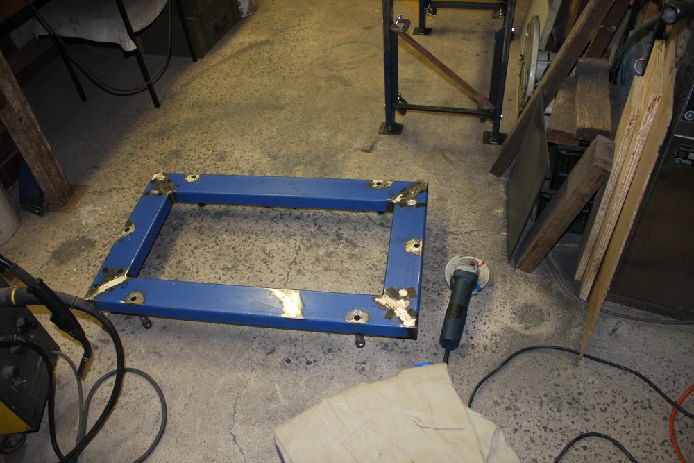
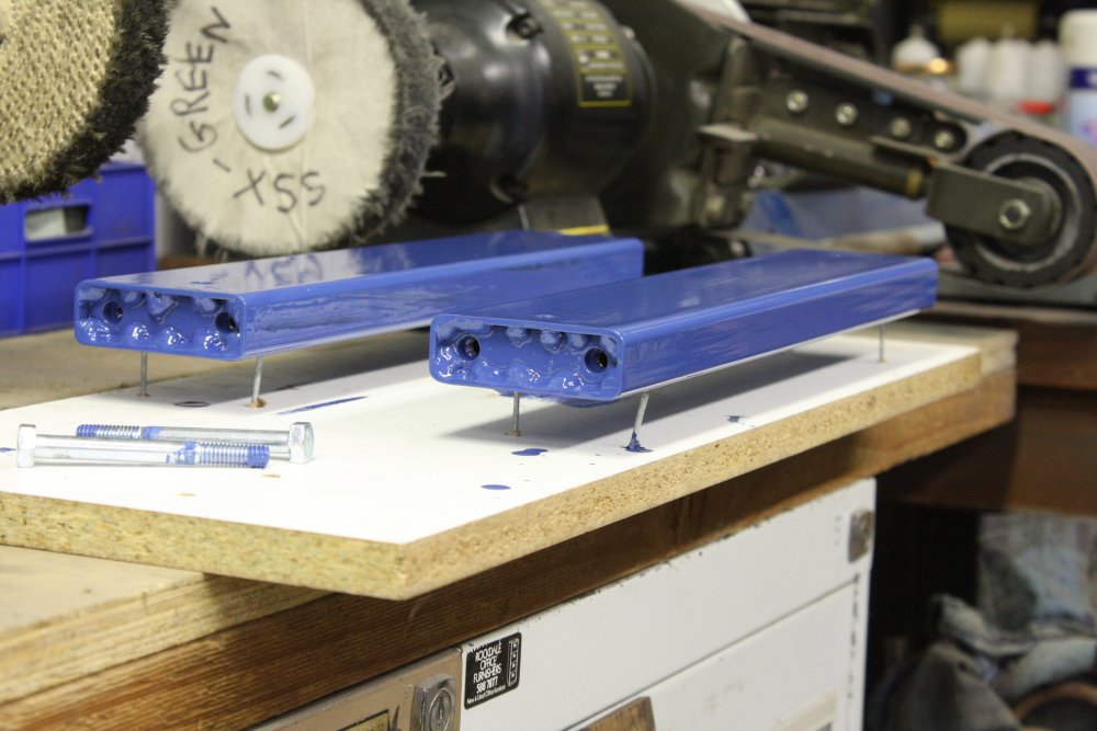
1. Nice fit! (Thank goodness, as I only had one piece of thick board suitable for this base.)
Incidentally, that diagonal streak of paint-stripped metal near the middle of the closer base piece, was due to the original blue beam having been stored for a while in my 'junk shed'. Which is open to possums. When I fetched the supposedly shiny new blue beam out to cut it up, I found a possum had peed on it. The metal was already rusting, despite the original paint. Like I said, possum pee is incredibly corrosive. I stripped off the affected area before it got any worse.
2 - 5. Making the top board. I wanted it to be only held down by the four bolts of the metal folder, yet be firmly held in place in the horizontal plane. Hence the four wood blocks, that are a tight press-fit inside the upper frame.
Actually I'm really pleased with how well everything is fitting. In preparation for mounting the machine I put the end brace panels in, and all their bolts slide in easily too. So far there's not a single bolt hole misalignment anywhere in this construction.
 |
 |
 |
 |
 |
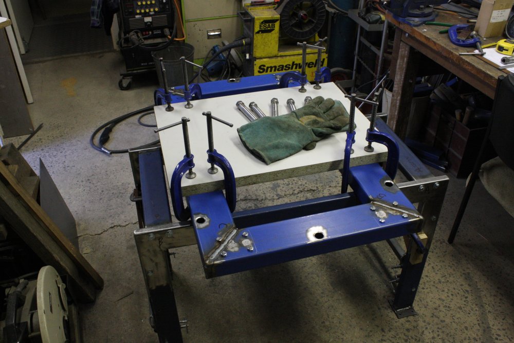
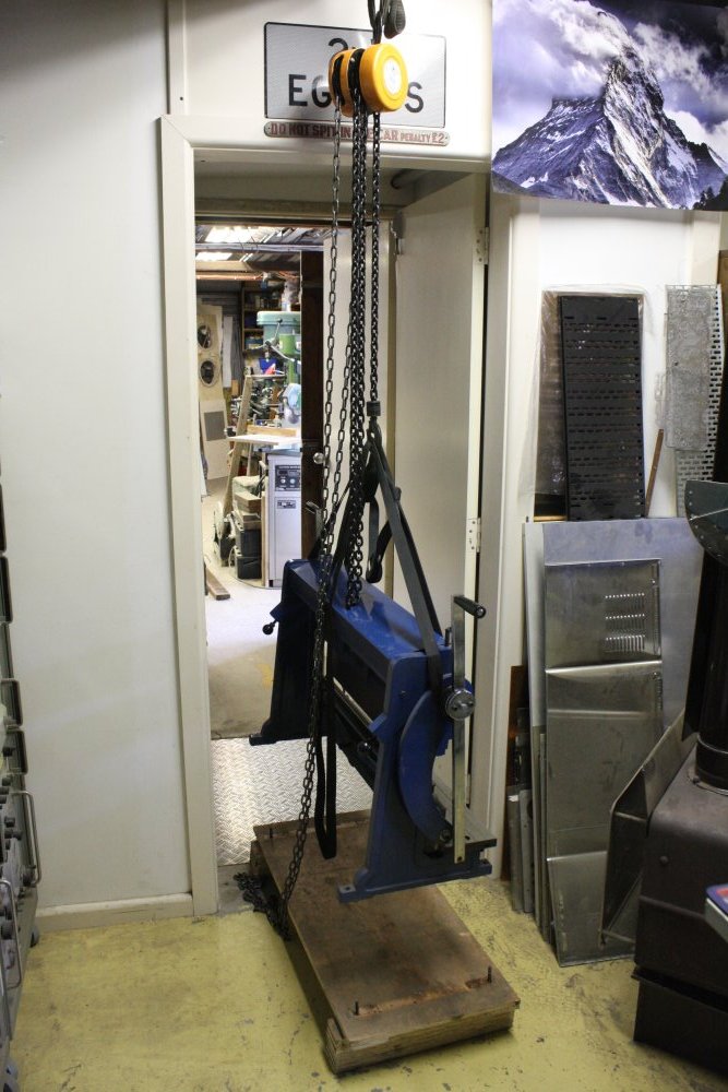
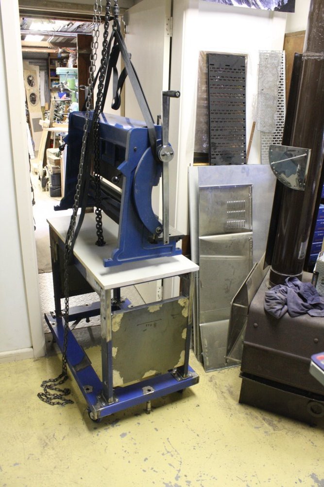
1. And so, the big moment. I can finally put the machine on top of the stand to mark the hole positions. It's very hard to drag the machine around, so I used the nearest available adequate lifting point. A beam over the doorway to the main workshop.
I'm glad to see the last of that old wooden base from the original shipping crate.
2. Lowering it onto the stand. It would be nice if I wouldn't have to do this all over again later, but will have to. The stand has to be disassembled for painting. Oh well.
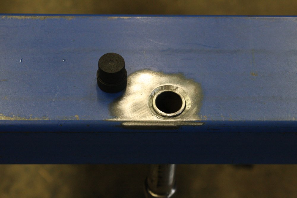
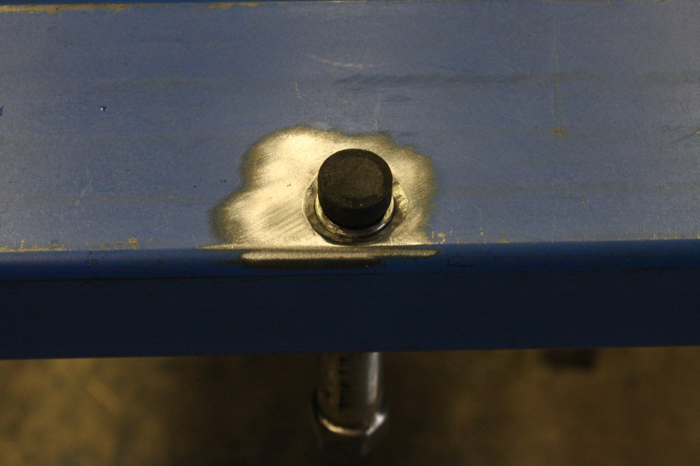
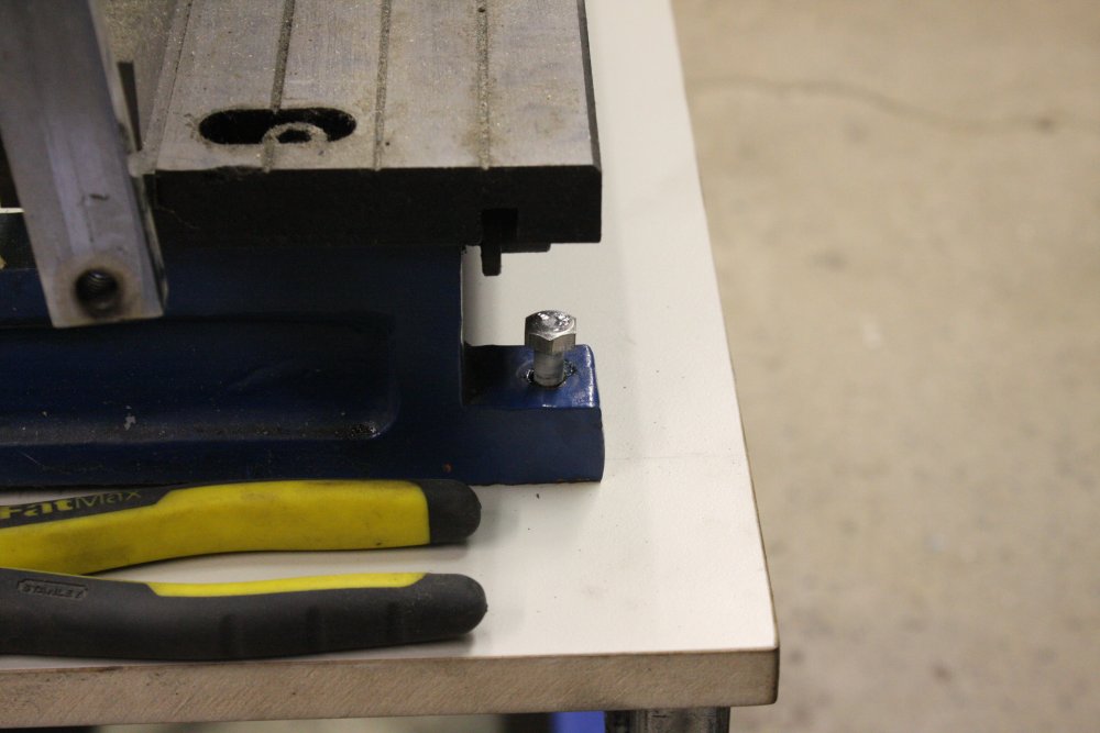
3 - 4. With the machine lined up on the top board, next comes marking the actual machine foot hole positions onto the board. Slight problem — two of the mounting holes are obstructed above. They are also too deep for my right angle scriber to reach the board. So how to...?
Answer: drop a short red-hot bolt into the hole.
5. Makes a very definite mark! I did the same on all four holes, as it works so well. The burnt impression is also slightly conical (since I ground the bolt end to a shallow point), so center drilling in it is easy.
 |
 |
 |
 |
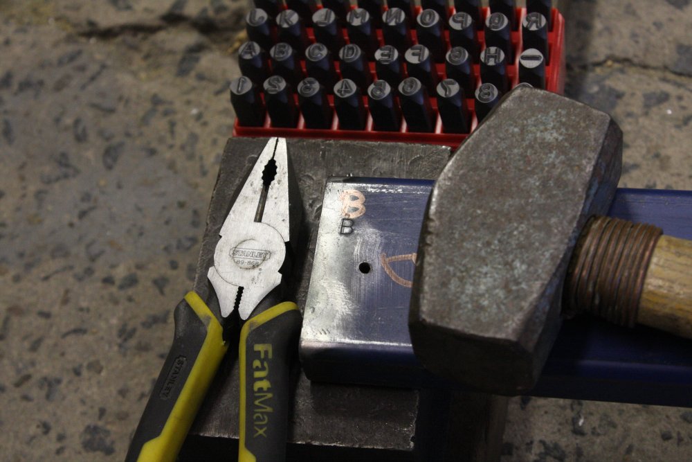
1. While the top cross-members are removed for drilling the mount points, I letter-punched the assembly orientation codes on them. Even if the overall frame is perfectly symmetrical (it probably isn't), I noticed the base screw points of the metal folder machine are not an exact rectangle. So orientation of these pieces matters.
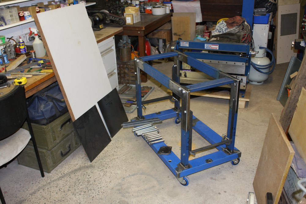
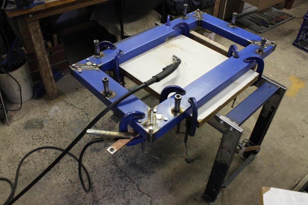
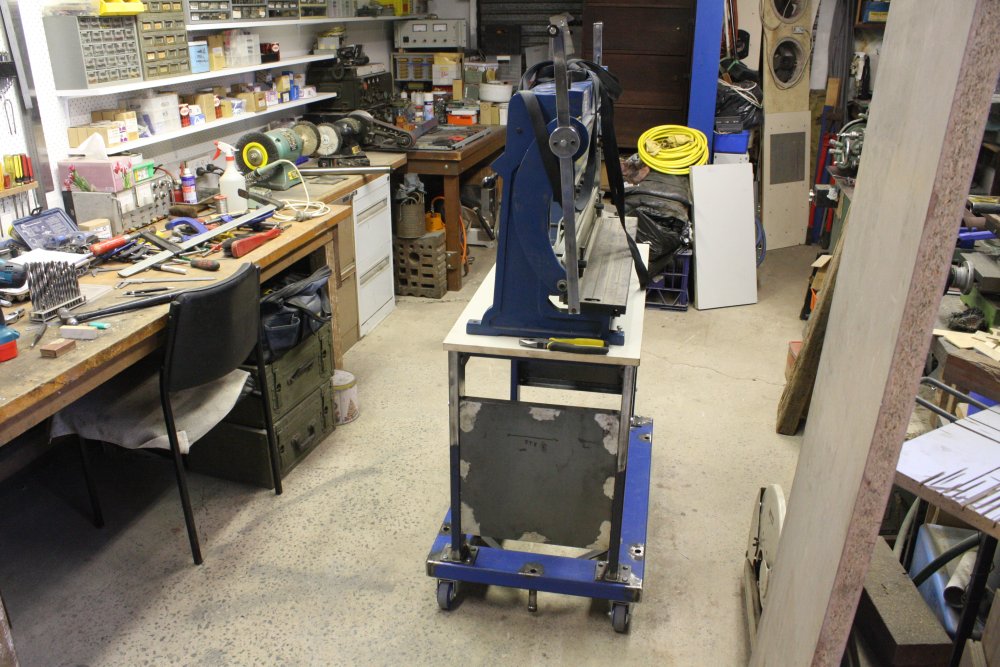
2 - 4. With it all assembled, I couldn't resist loading up the base with items I plan to store there. And yes, the idea of making the base so heavy there's be no chance of accidentally tipping it over sure seems to work. The poor castor wheels are barely coping with the weight, but they only have to bear it briefly whenever the stand is being moved. At other times the screw-downs take all the weight.
Pic #4 is where it will usually sit, for best working space around the bench and lathe. No, I still haven't sorted the boxes of nuts and bolts onto the new shelving. What with being ill for a month, and other time demands, it's been difficult enough getting this stand finished. It will be November tomorrow, so much for Spring Cleaning ha ha.
Next, I removed that pile of heavy things, winched the machine off the top, and took the frame entirely apart for painting. Sigh. Painting... why does the last stage of projects like this have to be the most messy and slow? It's as bad as watching paint dry. And painting. Times two.
 |
 |
 |
 |
 |
1. A toss up — which is worse? Getting paint in all the bolt hole threads and having to clean them out later, or making a bunch of taped-up plug bolts, then having to clean them up later? This time I chose the latter.
2. Lots of plug bolts.
3. Then there's improvising some way to suspend parts for painting. In a relatively small space, that you'll have to move around in while the paint is still wet. This stuff takes half a day to even get touch-dry, and at least a full day before it can be handled. Really should be two days before the second coat, but I never have that much patience.
4. Nail point supports for the cross pieces.
5. The base fill panel and top board are chipboard & MDF, so it's best to seal the edges. Of course I forgot to do this at the same time as the first coat on the metal frame, so these things held up reassembly for another day. Also I'd made the top board locating blocks a press fit in the frame, doh... so had to unscrew them and shave 'paint thickness' off the outside edges. This is all just standard painting annoyances, in my experience.
 |
 |
 |
 |
 |
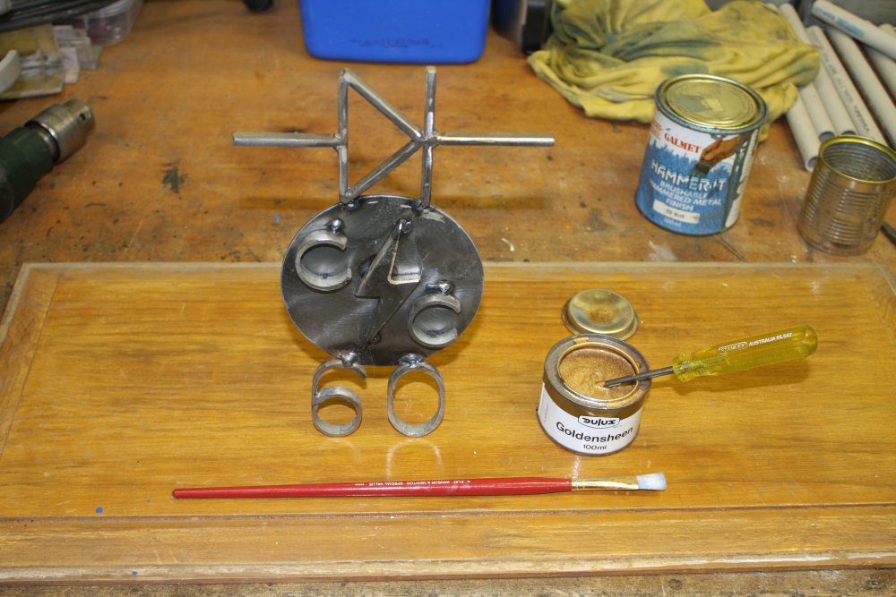
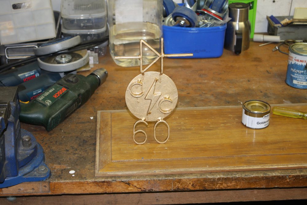
1 - 2. Painting something that was not annoying. Quite the opposite. It's an 'award' some friends gave me on my birthday recently. Those with knowledge of the Urbex scene may get the significance. It was bare steel, and I happened to have some 100% historically appropriate gold paint. Despite being (probably) very, very old and separated in the tin, it mixed back up easily enough.
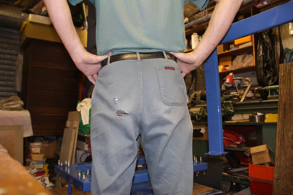
3. More asides. My painting pants. I have no idea what the locals think when I need to go to the shops for something while painting, and couldn't be bothered changing into less holy (sic) robes. Well, they match the beard.
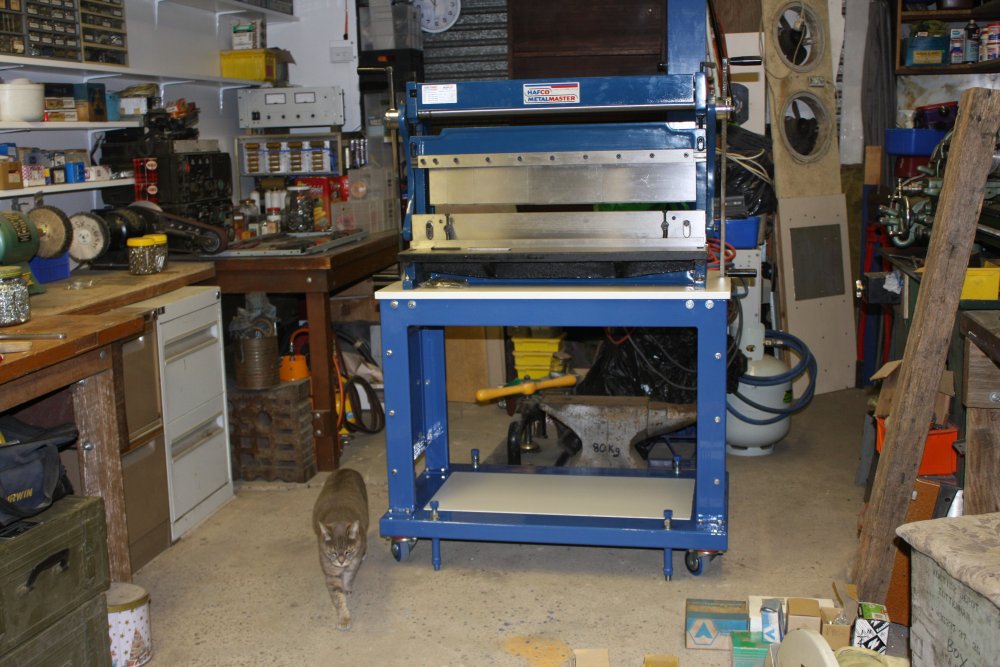
4. Cat! She's Tiny, one of two sisters I've had since kittens. Pic included because...
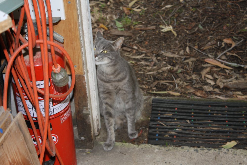
5. Cat! This is not Tiny. This is an entirely wild stray tomcat that took me about a year to befriend. He's *huge* compared to my other cats. Wiry build, but so large and lanky he's very heavy. Very smart and wiley puss too. For a long time he'd vanish instantly whenever he saw me. Gradually I let him get accustomed to me being around and not caring whether he was in my yard. There were a few months where I was able to be doing stuff or just sitting on the ground only a few meters away from him, but no closer. Pointedly making it clear I knew he was there, but indifferent. He'd sit and watch me, alert and interested looking.
Then one day while I was simply sitting nearby, he suddenly gave a little chortling 'prrt!' sound, got up, walked over to me, and head-butted my leg. I never before saw a cat make such a sudden, definite decision. Cool.
By now I can pick him up with no trouble. He likes being up at head height and looking around from that vantage point. He'd apparently never been inside a building before, so getting him comfortable with that was quite an amusing process. These days he'll sometimes walk in and say hello. Picking him up is like holding a small gray panther. It's great. Even better, he's smart enough to let me know with his voice when he's had enough. As opposed to escalating directly to claws and fangs, which is something I expect could be very dramatic from this big strong fellow.
 |
 |
1. In hindsight, maybe it would have been better to let paint get in the threads. Untaping and cleaning off the plug bolts afterwards was a pain in the butt.
2. Since my anvil is now going to be relatively easily accessible, even though not yet in my future 'forge and casting' workspace, I wondered what condition the top face is in. Bought years ago and in storage since, and probably never used for decades before I bought it, it's too dusty and rusty to really tell. A quick run over with the stripper disk, and hmmm... It could do with some attention.
So here's another diversion. I can weld metal on the dings and edge chips and grind back to clean it up. But I think a bit of research first on whether that's a good idea or not. Are these things hard-surfaced, or plain mild steel? I have no idea.
Stand done! One line on my todo lists that can be ticked off. There are plenty more. For instance finishing sorting out and arranging my stock of nuts, bolts, screws, nails, etc, that's still underway in this photo.