I'd set myself the task of making some nice stainless steel railings for an outdoors landing and stairway at my mum's place. In retrospect, it might have been a bit ambitious. At the time I didn't realise I'd need to build two special tools just to have any chance of getting a usable end result.
I had a MIG welder, and knew I could make acceptable welds in stainless steel, so long as I didn't mind grinding down my messy welds to get a reasonable looking finish. What I didn't realise was that when welding pipe, if you try it by hand the result will certainly not be a straight join, due to never being able to get perfectly even heating around the weld. At least I can't; professional welders may not have that problem.
Anyway, it became obvious I needed some way to automate pipe seam welding. So in a rush I whipped up a motorised pipe rotator. The aim was to have a fixture to hold my MIG welder torch tip at the right distance from the workpiece (a tube), start the tube rotating, then manually trigger the MIG using an add-on button hand-control, watch the weld progress, and release the MIG trigger when the weld rotated round 360 degrees.
|
|
|
|
|
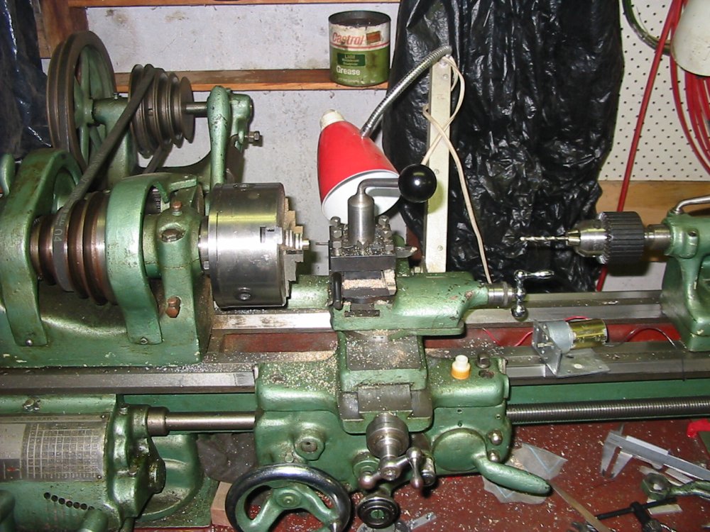
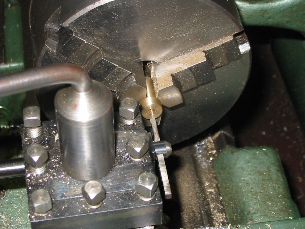
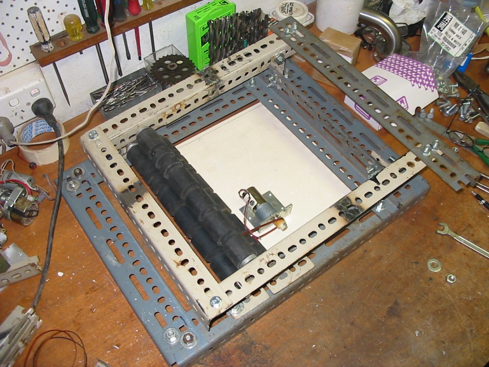
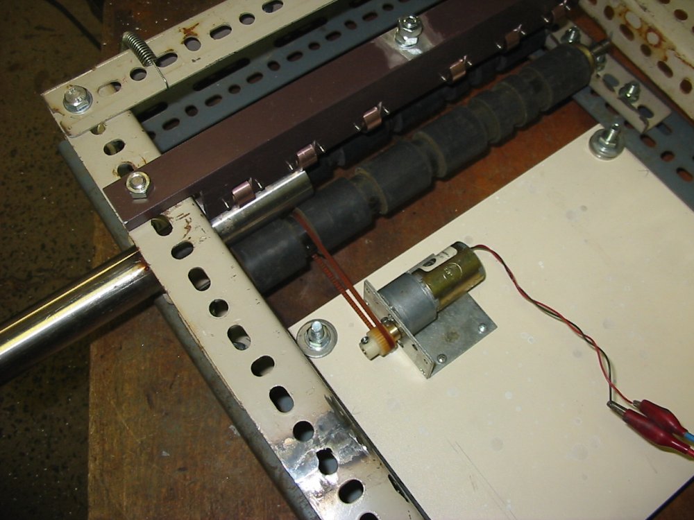
I had some big rubber rollers from an old phototypsetting machine. They'd do to grip the pipe. To turn the rollers, some digging in my box of junk motors found a small DC motor with a gearbox. Also a drive cog for a toothed belt.
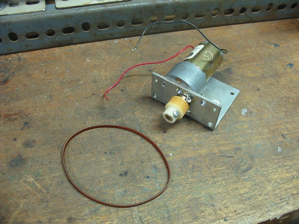
Pics 1 & 2 are turning a bit of brass to adapt the cog to the motor shaft. Pic 3 is the cog on the motor.
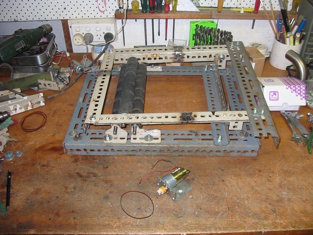
Pic 4 & 5: A frame made of Dexion sections, and the motor mounted to a slab of MDF - but not yet attached to the frame.
 |
 |
 |
 |
 |
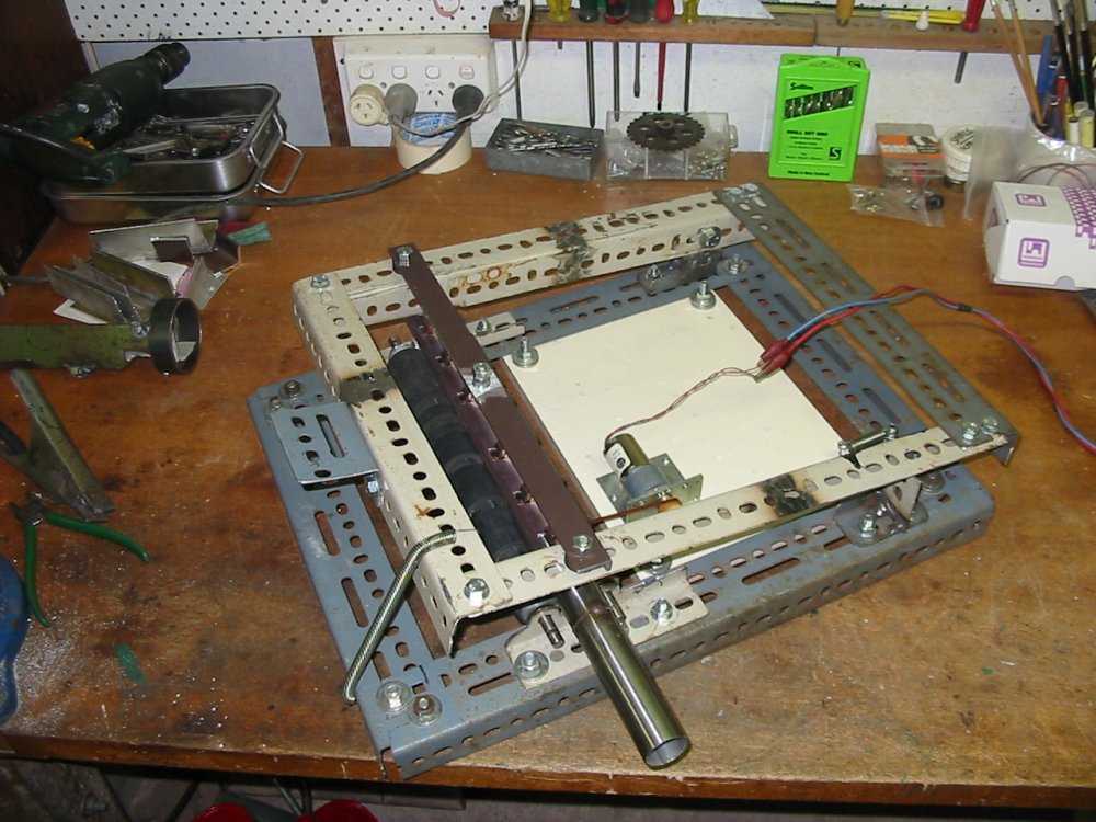
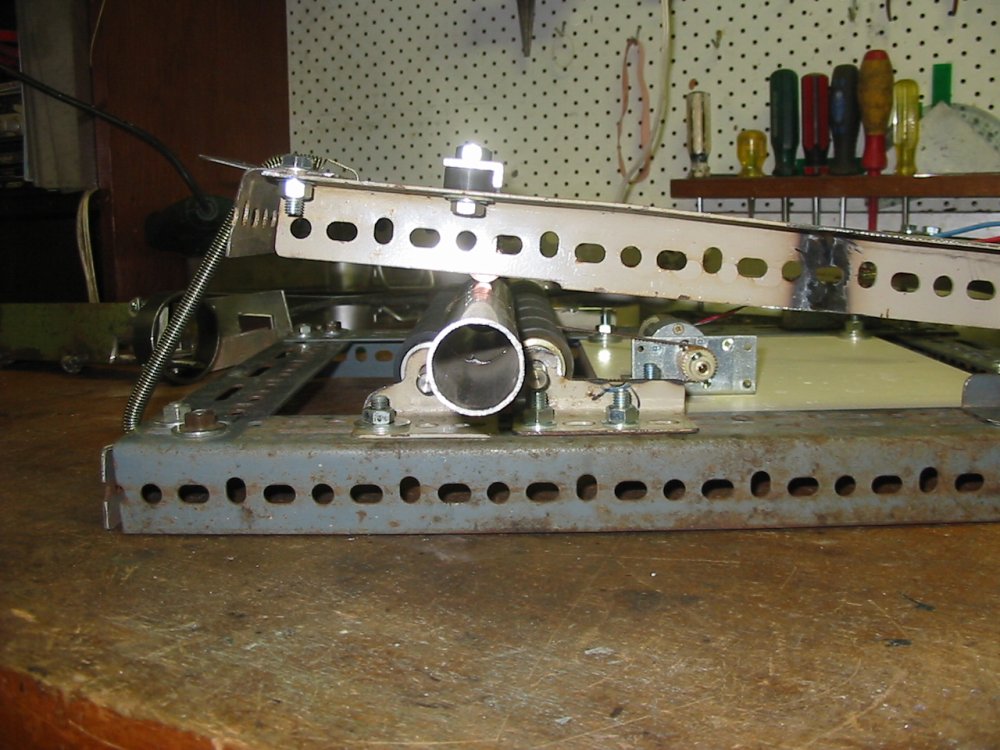
Now the MDF is mounted, so it can slide horizontally in the dexion frame. A spring pulls it away from the rollers, so the toothed belt is kept under tension.
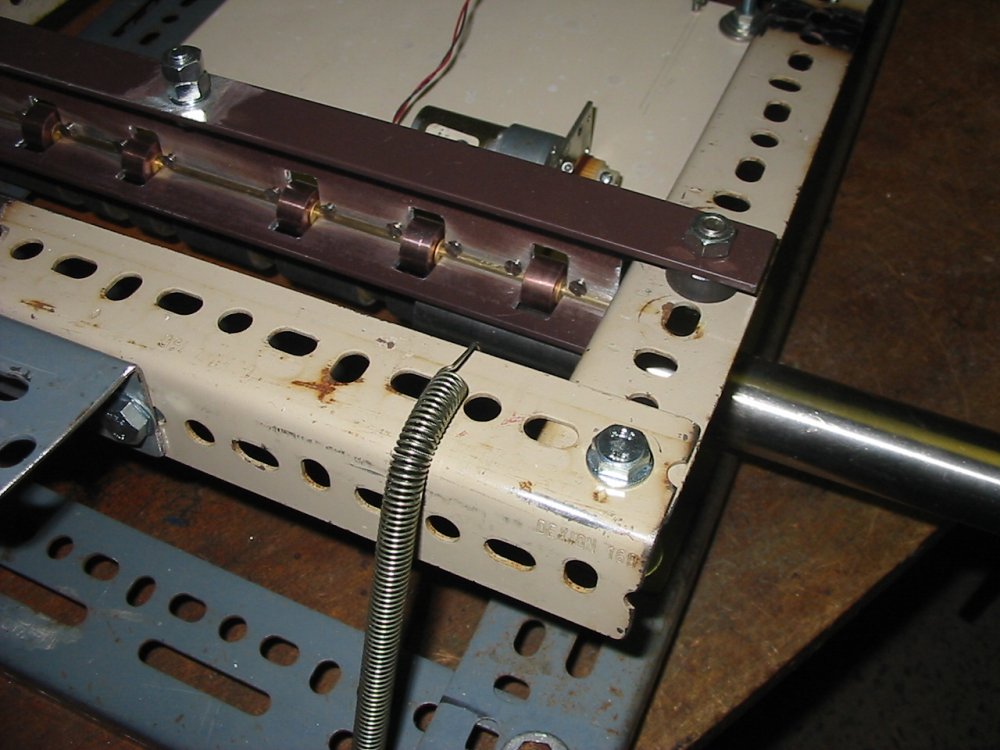
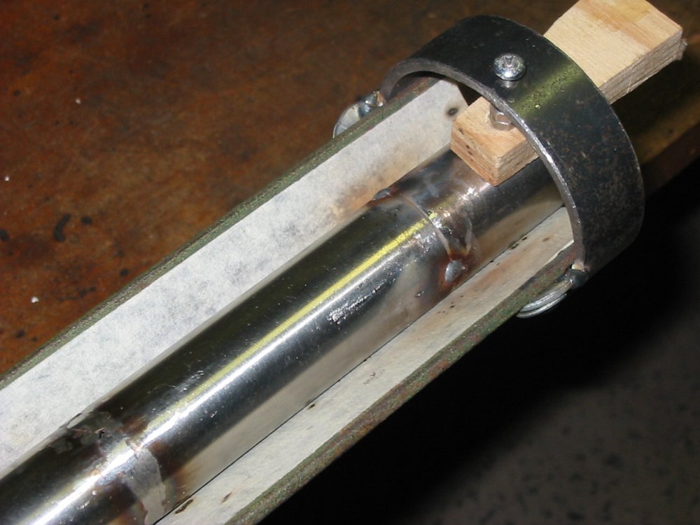
Pic 2 shows the welder's ground electrical contact to the pipe. The brown aluminium section (an offcut from my recent construction of a screened patio) is isolated from the Dexion frame, and carries a line of conductive rollers electrically connected to the aluminium by the brass rod they roll on.
I was lucky to have found a box of these rollers years ago. They appear to have been designed for just this application, ie making electrical contact to a rotating metal object. Apparently some sintered compound of copper and graphite, they have low friction and conduct very well. Unfortunately whoever made them managed to drill all the center holes a little off-axis, and maybe that's why they were discarded. However the material is soft and the holes were easily made a little larger and concentric in my lathe.
The big bright-plated bolt at the top is for the welder's ground clamp.
The Dexion frame is a clamshell, held tight on the pipe by a spring.
Pic 5 is a jig for holding pipe pieces axially aligned for tack welding.
 |
 |
 |
 |
 |
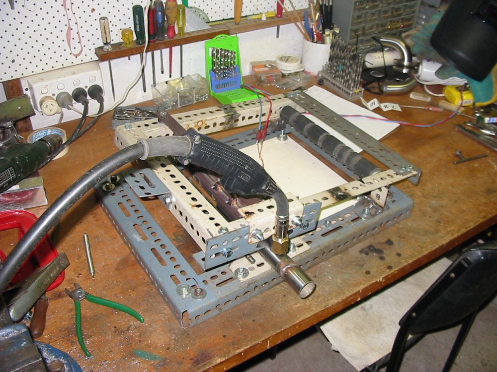
In pic 1 I'd added the mounting for the MIG welding torch. It allows the torch to be tilted relative to the weld surface, but I never did experiment with different angles, since vertical seems to work fine.
Then there was quite a lengthy interval of unsuccessfully attempting to get a speed control circuit working with that electric motor. Without regulation it was hopeless, since any varying load changed the speed a lot. One way I tried used a speed servo with a pickup from the roller driving the pipe to be rotated. However this resulted in a control loop with too much loop delay and noise. This seriously did not work. The resulting control loop was full of lags (for example the inertia of the gear chain) and I simply couldn't get it to be loop-stable and not hunt up and down in speed.
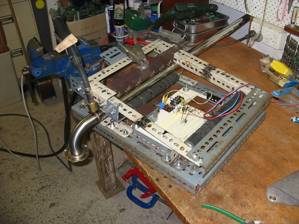
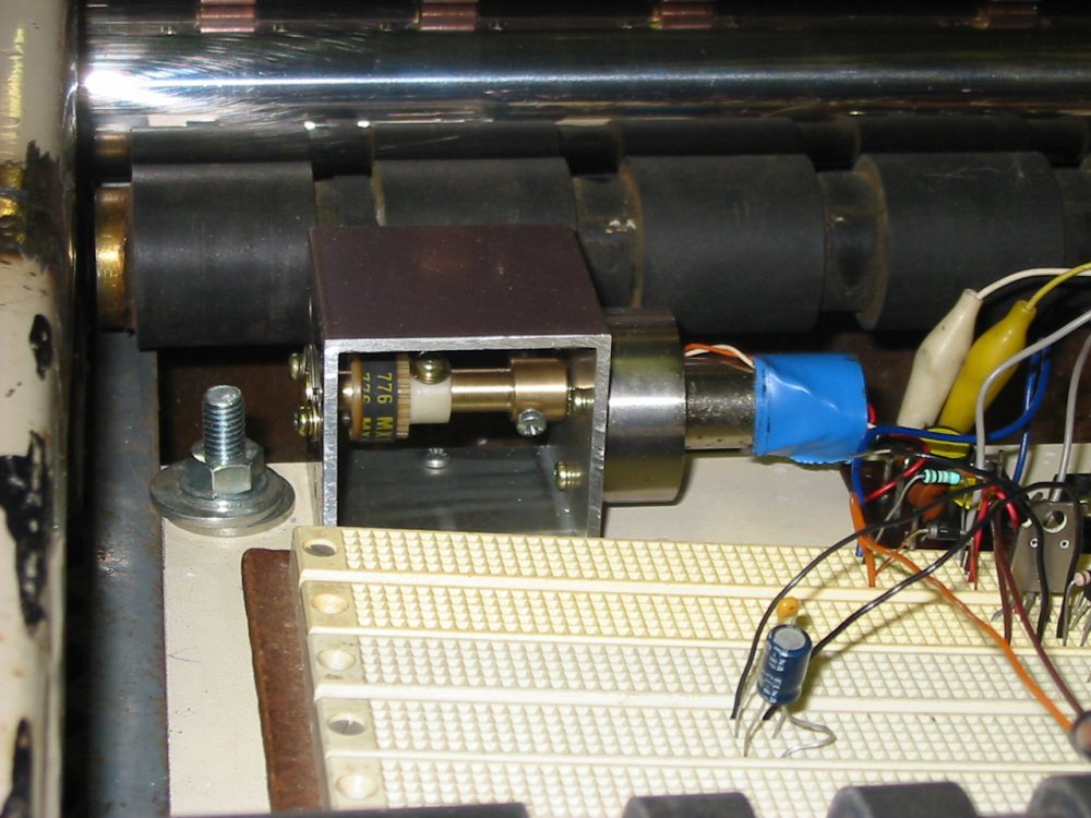
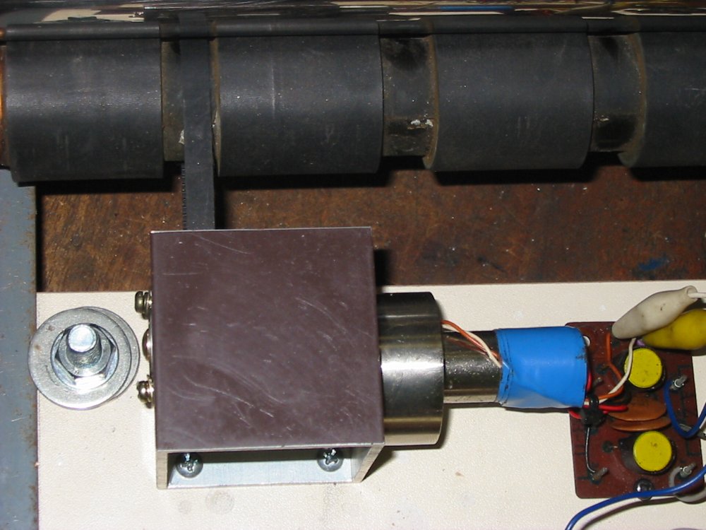
It seemed like a better way would be to take a speed measurement signal directly from the motor, before it was geared down. After some more junkbox rummaging, I found the motor seen in pic 2 and onwards. It's a carriage servo from an old laser video disk player, and has a DC motor with a direct tacho sense output. Which is conveniently also DC. After making a mount and adapter to the toothed belt for it, the speed control circuit was easy.
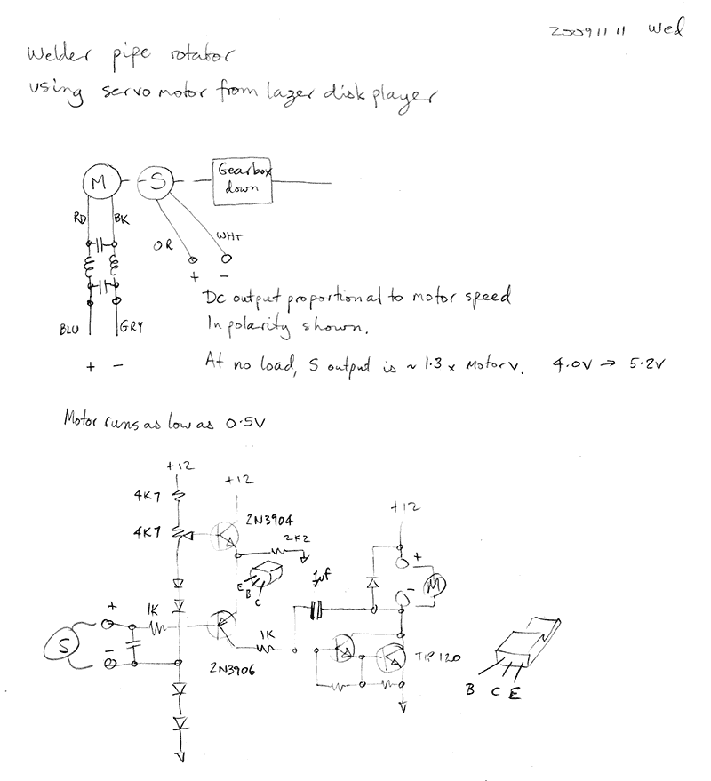
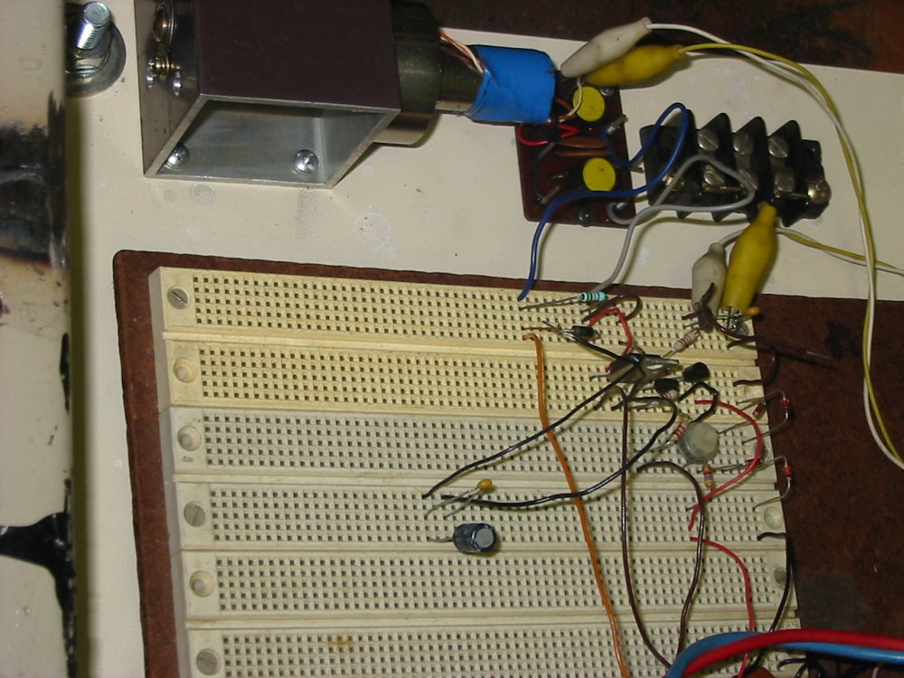
The speed sense output is compared to a fixed voltage (from the trimpot, buffered by the 2N3904), and the error applied to a TIP 120 darlington driver to the motor. A single miller slew rate limiting cap provides loop response control. Nice and simple; just transistors, no ICs. Years later tt's still in the prototyping plug board I originally developed it in. Yeah, I'm slack. But I have several of those protoblocks. If I ever actually need that one for something else, I can transfer the circuit to veroboard. Meantime, I just keep a dustcover over it (removed for this pic.)
 |
 |
 |
 |
 |
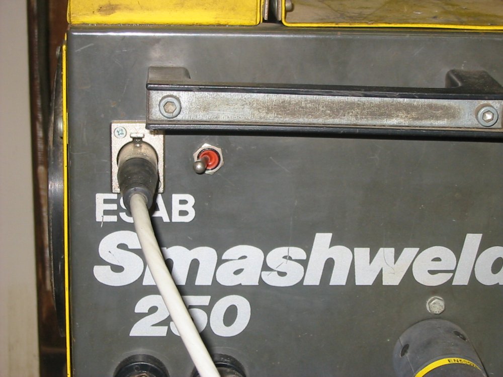
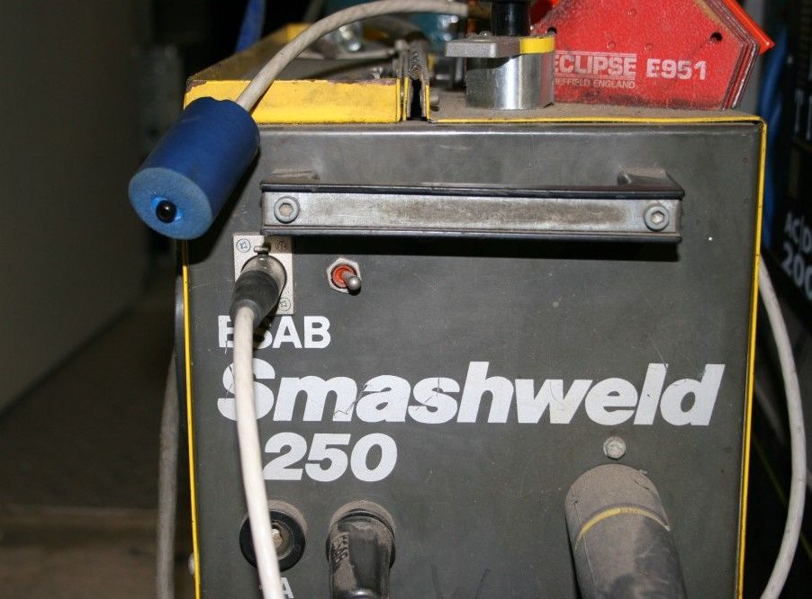
The MIG welder was a gift, years ago. It wasn't working, so I traced out the circuit of the control board and fixed it. For this pipe rotator I needed to add a remote trigger, and this is it.
The white cable ending in a dark blue thing is the welder hand switch for use with the pipe rotator. The button is an aviation variety, that requires firm pressure to activate. You don't want a MIG welder turning on accidentally. The button is held in a piece of blue rubber foam pipe insulation, to make a good grippy object. The switch next to the canon connector on the welder provides normal welder operation (to the right) or control via the hand switch (to the left.)
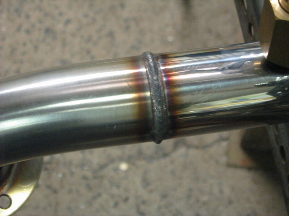
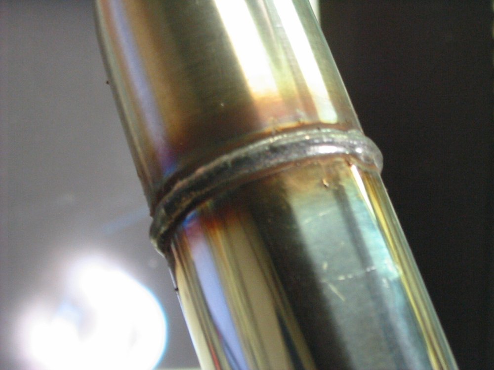
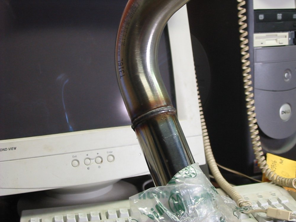
The resulting welds are quite nice. Only of course for a railing they do need to be smoothed down and polished. Which leads to the second special purpose tool I had to make for this project — a pipe surface grinder.
By this time I was a bit fed up with so much stuffing around just to weld some pipe, so didn't take any pics of the grinder construction. Just plowed into it, trying to get it done asap.
 |
 |
 |
 |
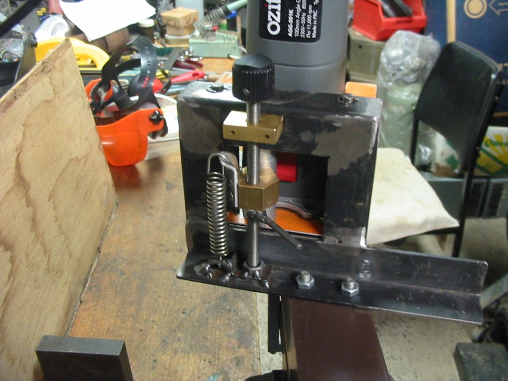 |
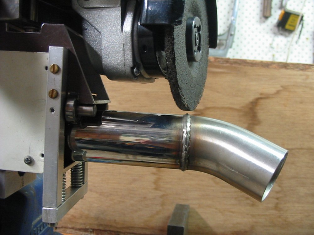
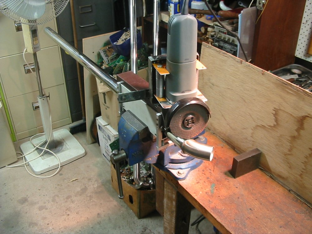
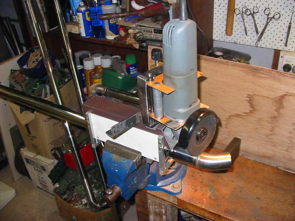
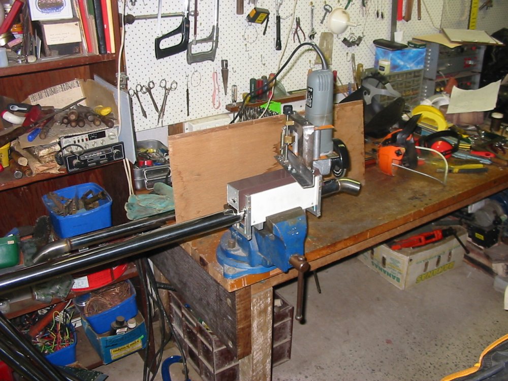
Here it is, finished. I bought a new (very cheap) angle grinder, and mounted it in a frame that allowed fine adjustment of the disk height relative to the surface of the pipe. Either the grinder assembly can be rotated around the pipe by hand, or the grinder can be held in a vice and the pipe rotated by hand.
The pipe rolls on four ball races, held against them by a spring loaded rubber roller. This allows the pipe to be moved lengthways slowly as it's rotated. The height adjusting screw (black knob) has a lock lever. For really fine height adjustment, I just push a little on the angle grinder body.
This was for one of the maintenance jobs at my mum's place.