As part of the setting up for some experimental work, I needed another equipment rack as part of the cluster adjacent to the large vacuum chamber. There'll be four modules in this cluster; in plan view like so:
| Vaccum chamber (top) Hi-vac pump (below) (Oil diffusion, or if I can ever afford one, turbo molecular) |
High voltage supply in Faraday cage (top) Gas mix control system and vacuum roughing pumps (bottom) |
| Helium-Leak detector (mass spectrometer) |
Monitoring instrumentation rack (Pneumatics supply compressor in base) |
Fortuitously, just as I was about to start working out how to do that part, a friend asked if I'd want a damaged rack frame they were throwing out at his work.
"How damaged?" I asked. He said it had been dropped, and was bent.
Hmm... maybe it's repairable. And it's free, so of course I said yes please.
Once I'd gone and picked it up and had a look at it at home, it seemed likely I could fix it. It was a modern all-welded steel frame by HP (Agilent I suppose) and had been dropped on a corner. As a result the frame was distorted out of true in just about every possible degree of freedom. Additionally the vertical struts all had a significant uniform inwards bow, which was obviously a natural result of the way the rolled steel shapes had been formed. In other words, a result of defective design/manufacture.
What with that bow and several other stupid elements of the design, I wouldn't have been surprised to hear the rack had been deliberately 'dropped' to write it off and claim insurance. Quite sad to think that the company which was once Hewlett Packard could now produce such a lemon, in something so simple as a rectangular steel frame.
The top cover came with it, but I was told the side panels were "mangled beyond use, and binned." Though I suspect I could have repaired them to good enough for my purposes. But never mind, in general this rack suits my needs well. For one thing it's quite short, which means I can mount it on top of the space for the air compressor unit. The only real problem with it (apart from being bent) is that it's too deep. My work area isn't very big, and I can't aford to throw portions of it away on things like empty space in the back of racks.
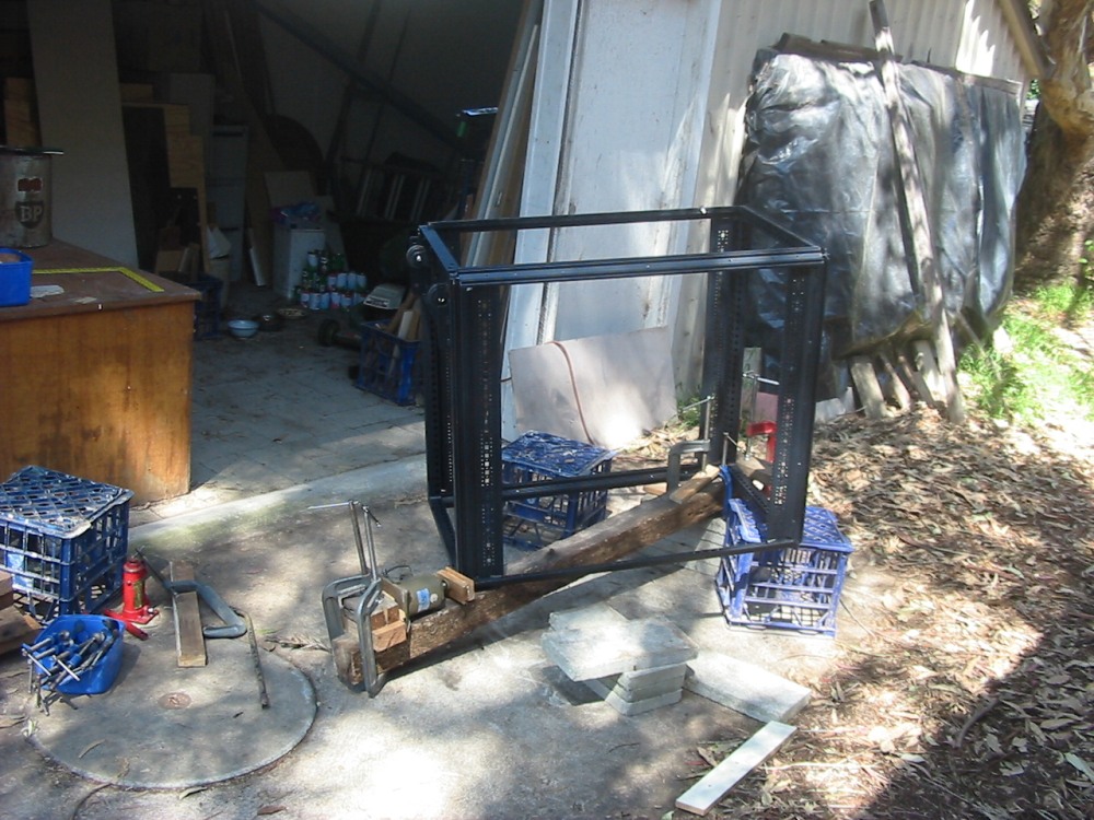
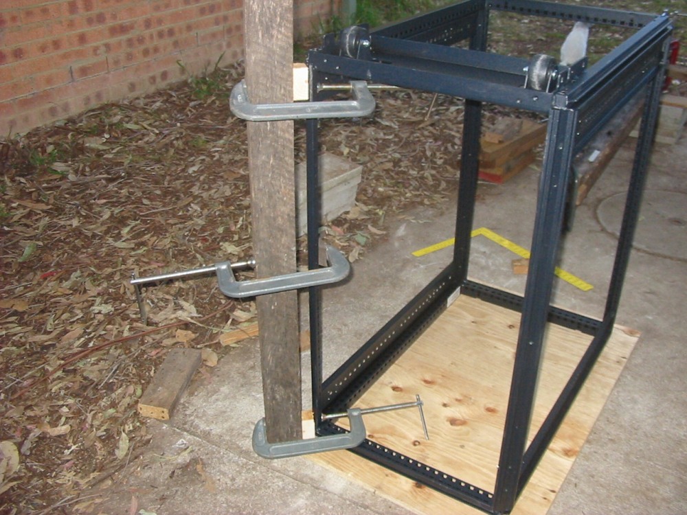
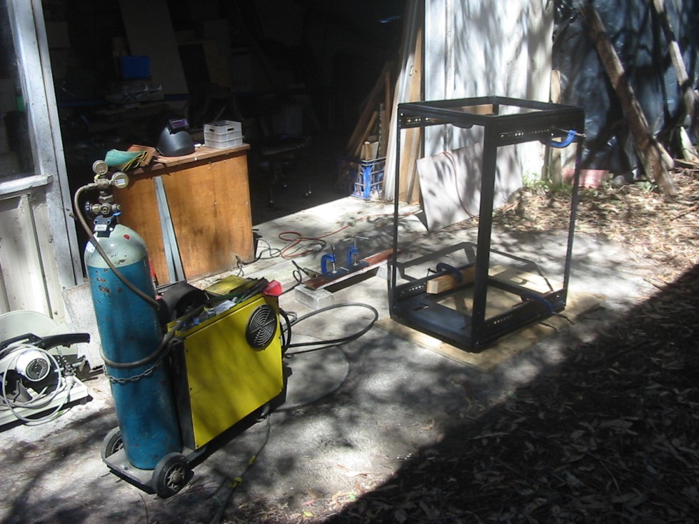
First things first though. Could the rack be unbent? This was going to require some fairly high but controlled forces. How? Well, like this: (click on thumbnails for full size images)
|
|
|
|
|
|
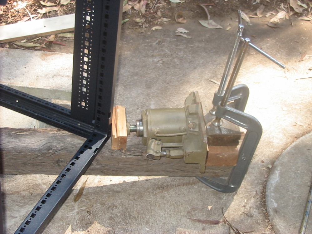
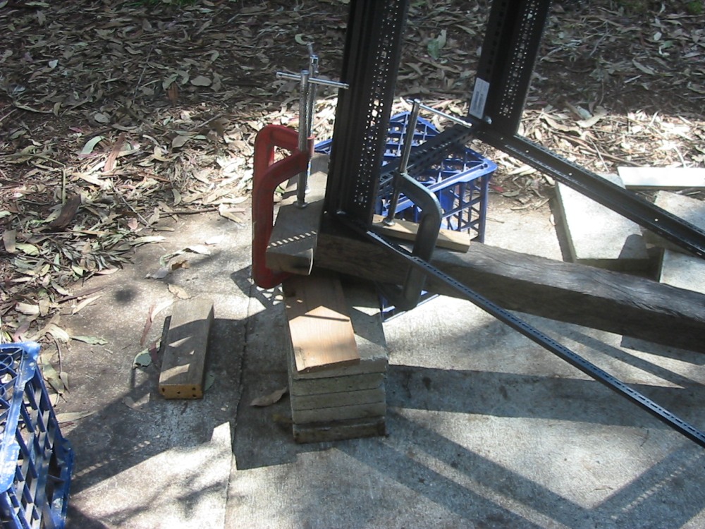
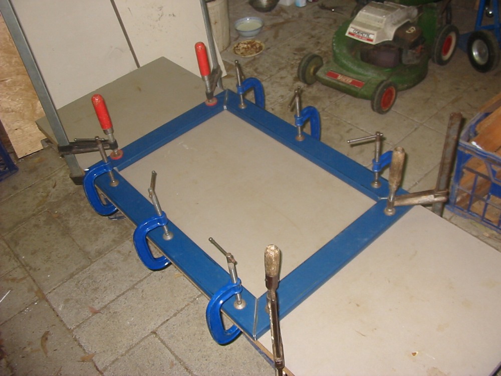
An old hardwood fence post, G-clamps, and a chunky hydraulic jack from a truck. For each rack face that needed 'persuading' to be square again, some pushing like this worked. It was an iterative process, doing faces in turn, each time picking the one that was most out of square. The corners are welded, and since the whole thing was only a few degrees skew in any direction it could be just bent back. Mostly the paint didn't even flake off.
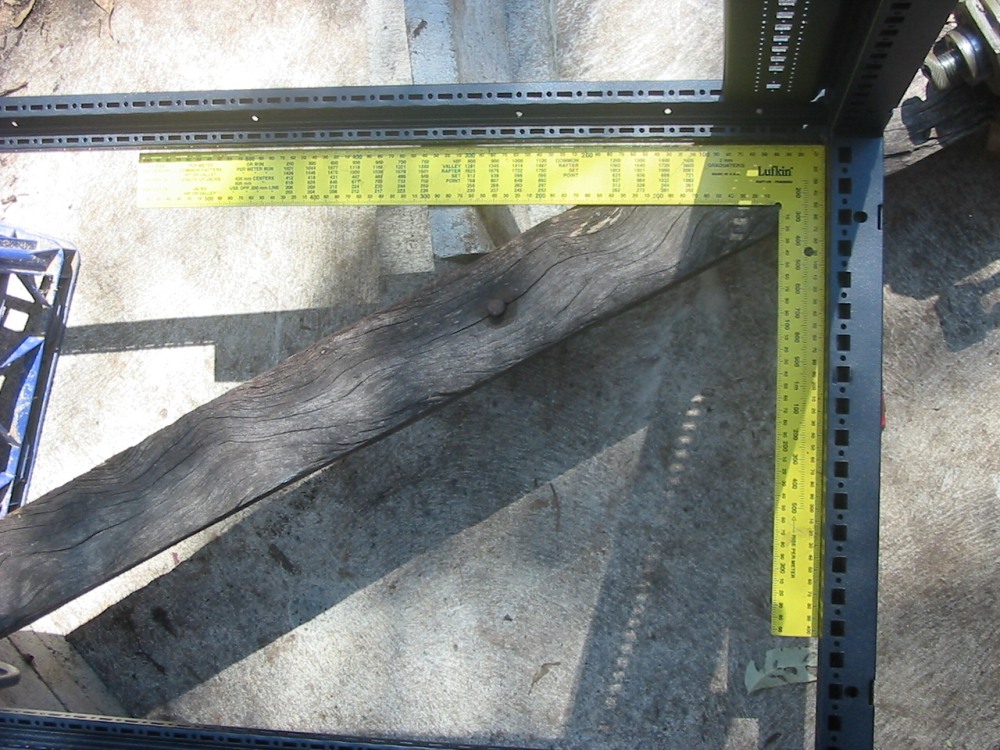
Once it was all square, the bowed sides were straightened out like the last pic above. This required forcing it into a bow in the opposite direction, letting off the tension and checking it for straightness; if not, then bend it more.
|
|
|
|
|
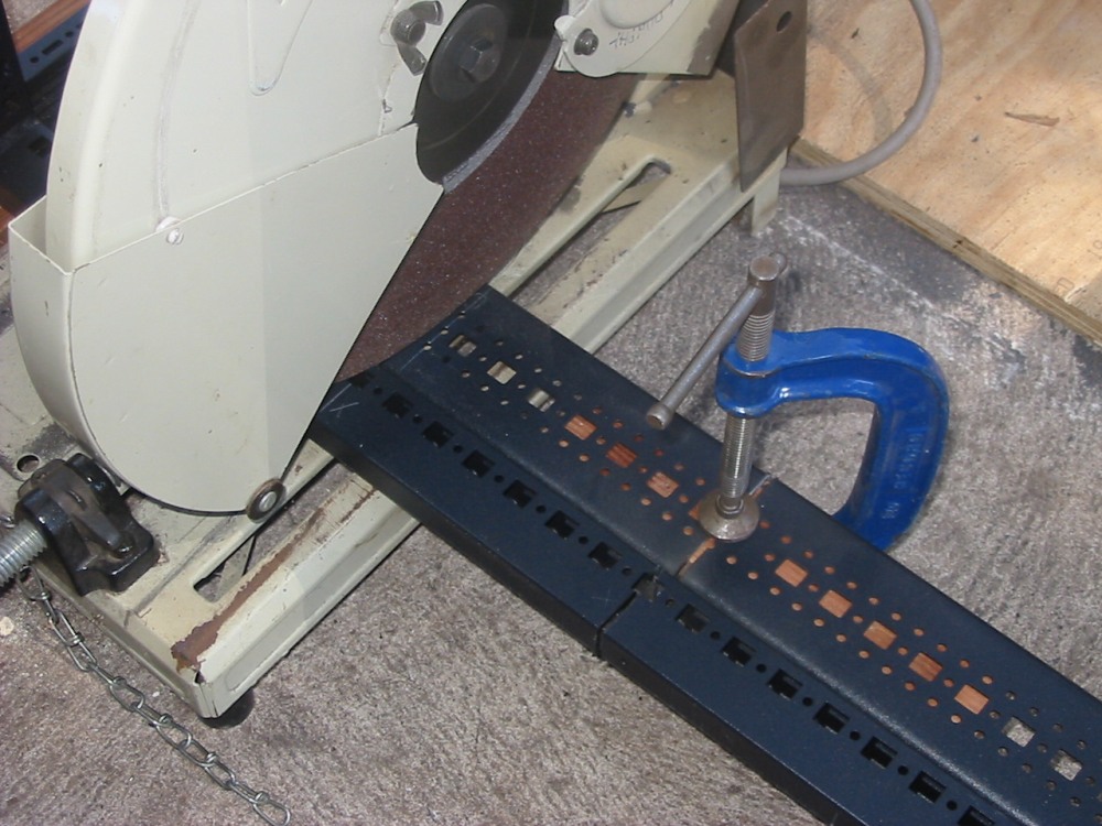
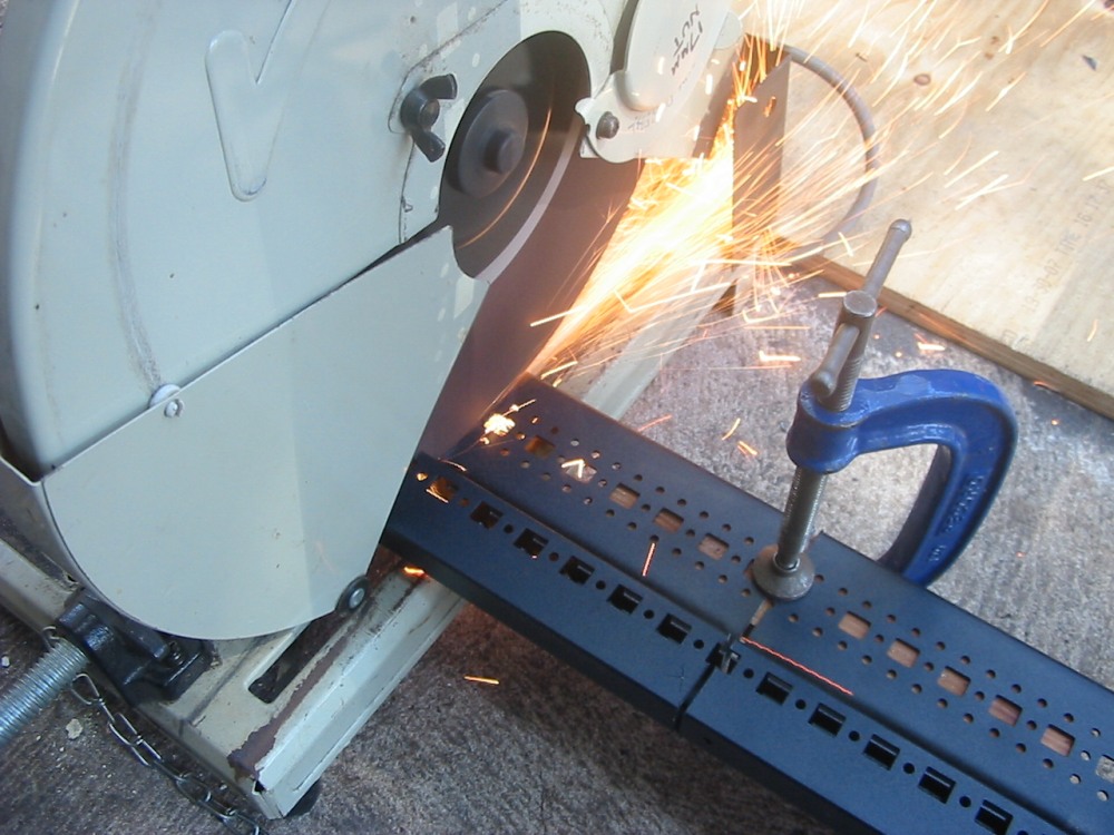
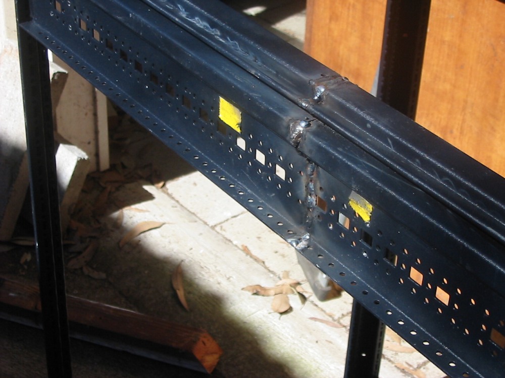
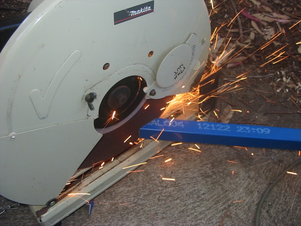
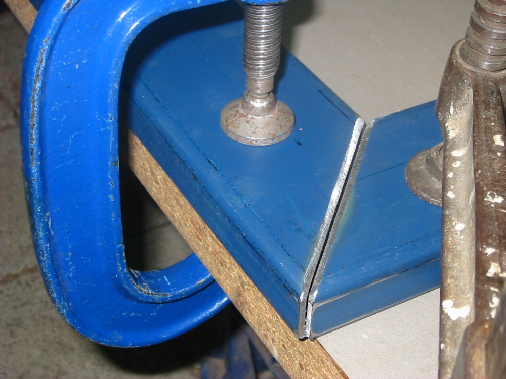
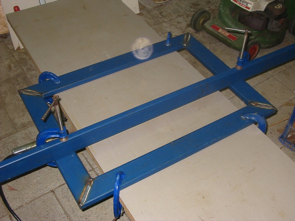
That left the problem that the rack is too deep. But hey, it's made of steel, and that means if it isn't the shape I want, it's going to become the shape I want. First step was to cut out the excess length from each horizontal side strut.
|
|
|
|
|
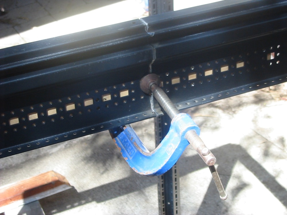
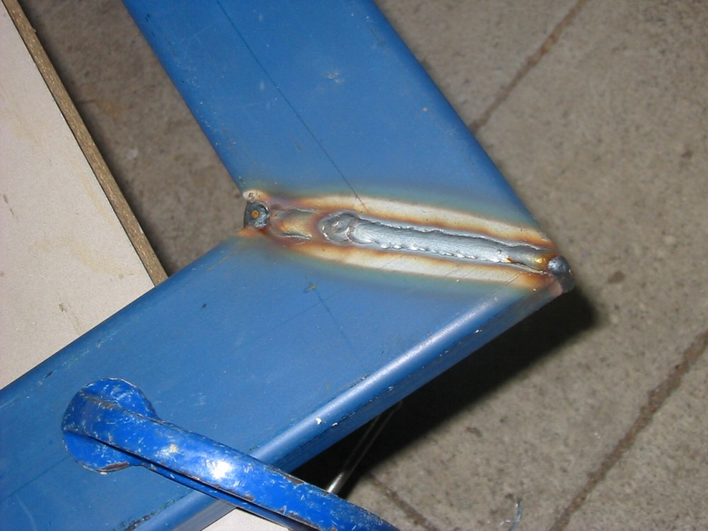
Then weld the two parts back together. For some reason I thought at the time it would be enough to just bevel the butt join edges, while not stripping the paint back a few centimeters around the weld. I won't make that mistake again. This was before I discovered the very effective paint stripping disks that I used for later projects.
|
|
|
|
|
All the same, it worked out OK once the welds were ground flat.
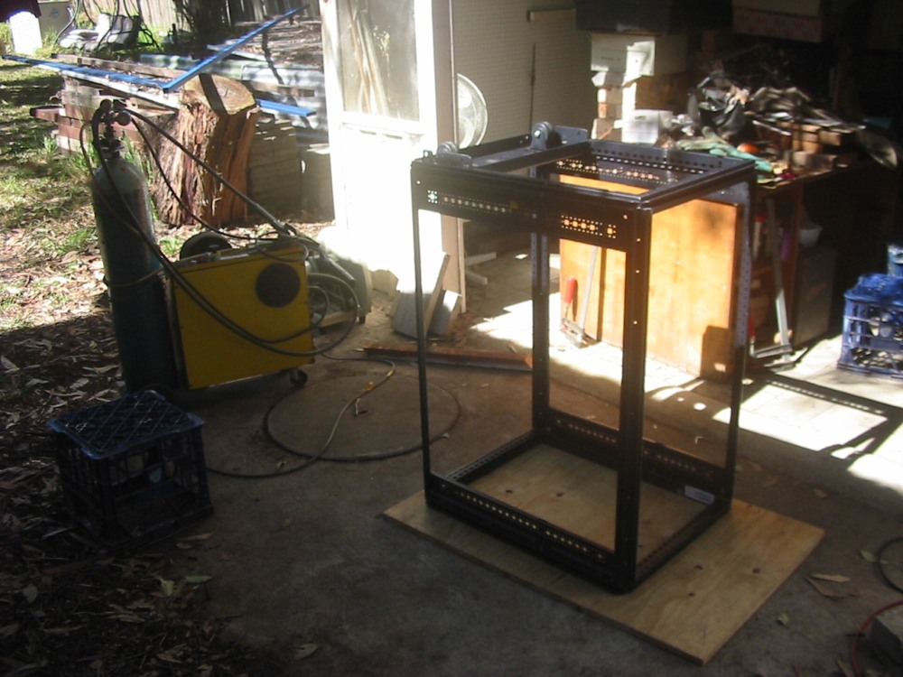
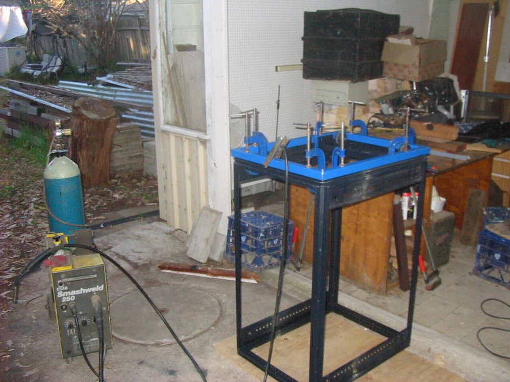
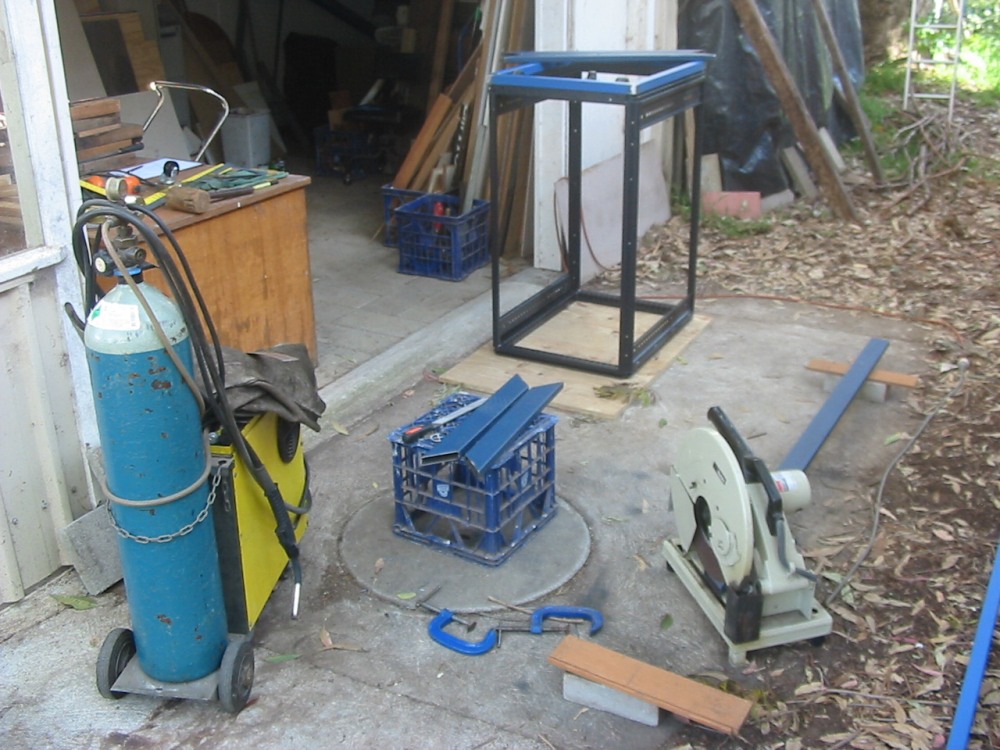
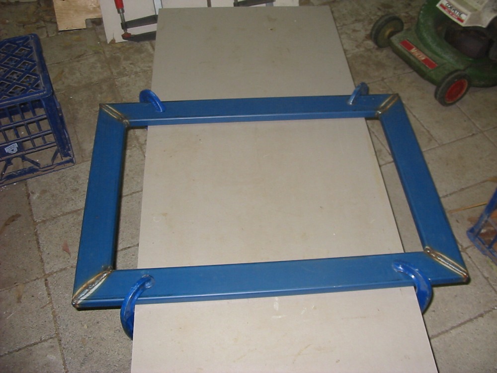
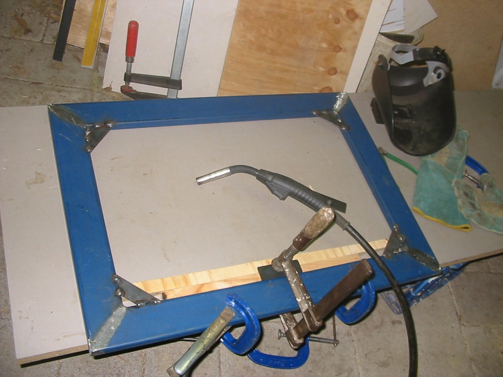
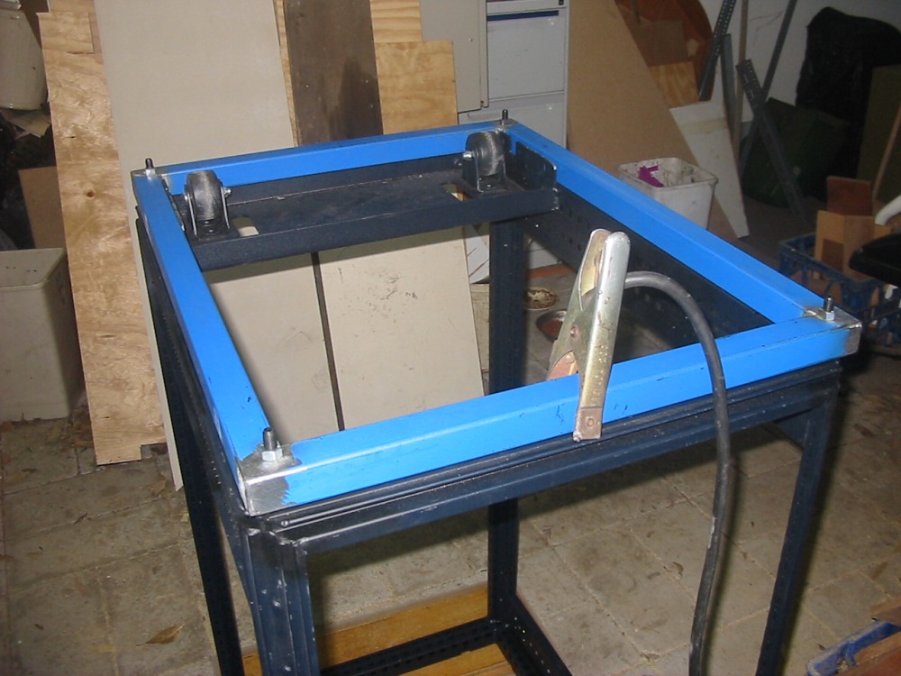
The next job was to make the roller base and stand which the rack would sit on top of. Starting with the frame that the rack base would bolt onto.
|
|
|
|
|
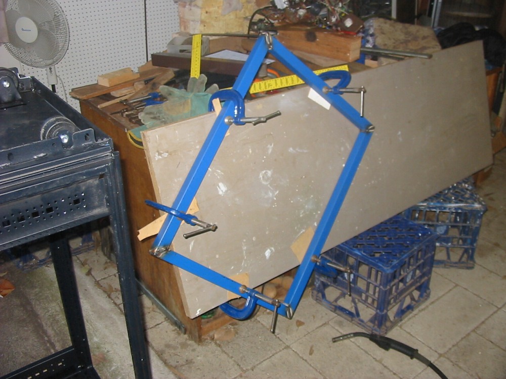
Once that was done, then the roller base size could be determined by simply laying the parts on top, working out placement of the roller wheels etc by direct comparison. This is the way I tend to work for one-offs like this, where there is something I have to match against. There's no point drawing up plans with measurements. For this any paperwork is just a waste of time and also asking for errors. Notice there's no tape measure in the photos? That's because pretty much everything is being done by transfer measurement.
|
|
|
|
|
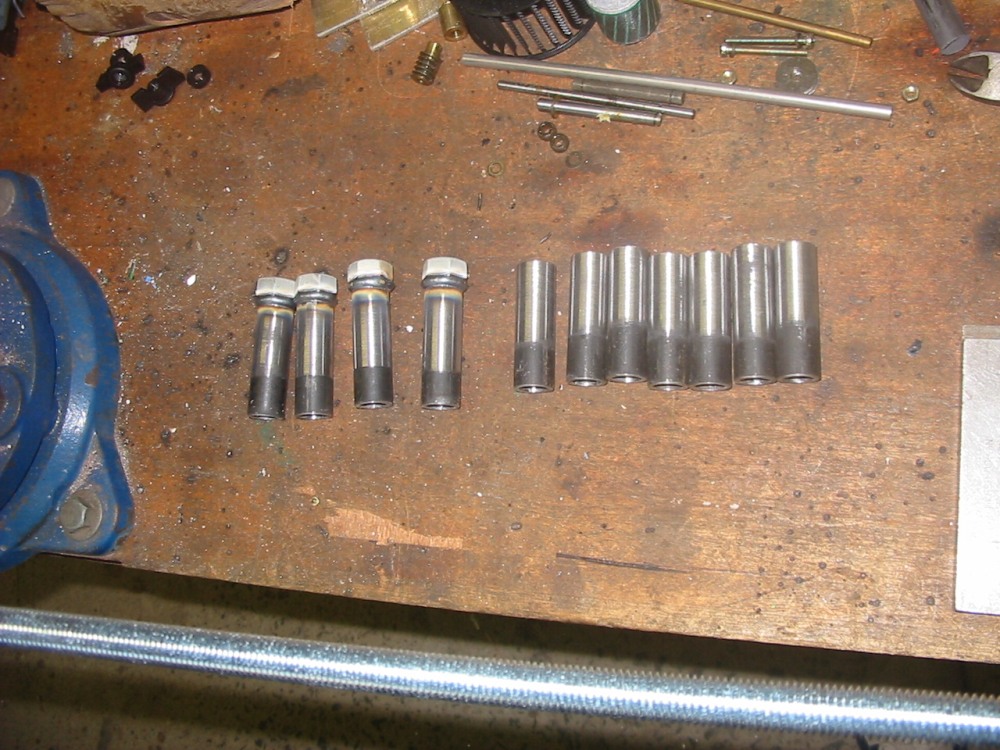
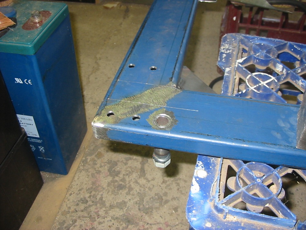
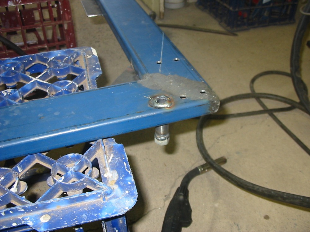
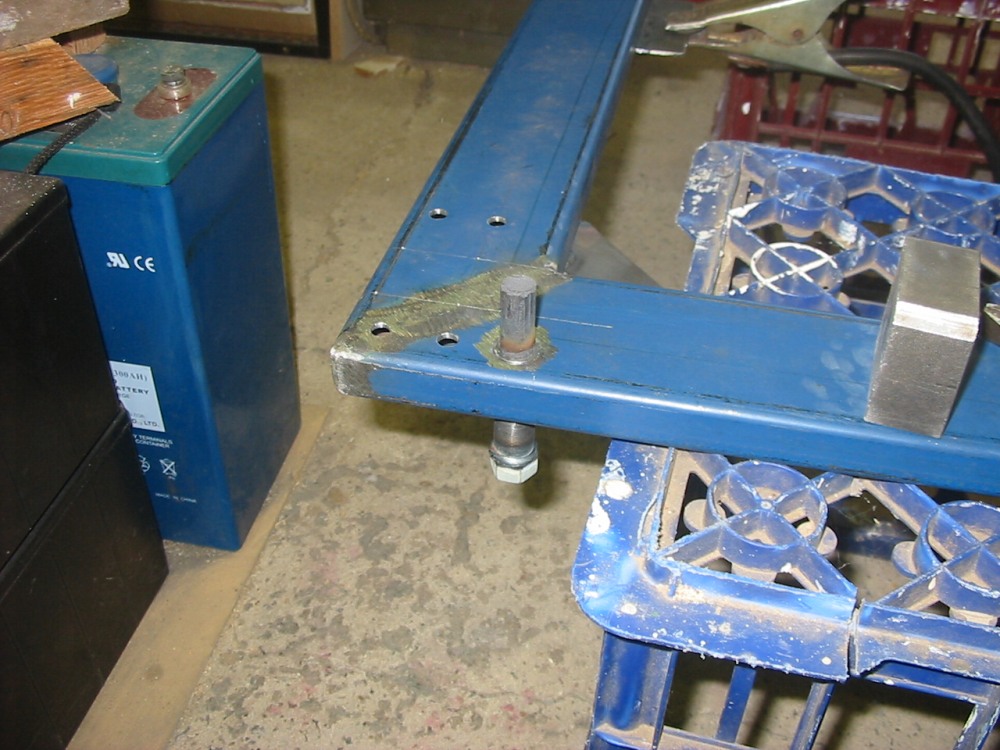
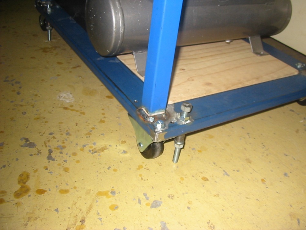
The base has some tabs to support a plywood center panel, holes for the wheel mounting flanges, and tubular mounts for screw down threaded rods that can be used to take the weight off the wheels, fixing the rack in place and making it stable.
|
|
|
|
|
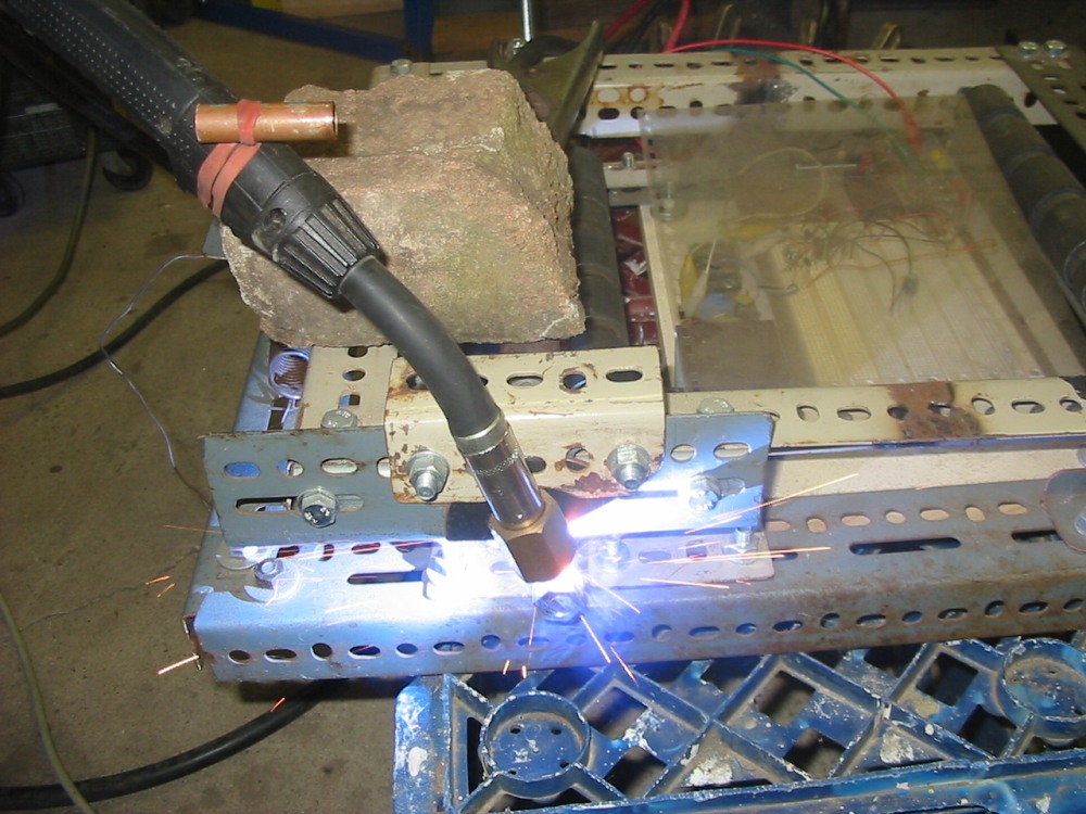
Nuts are welded onto the ends of the mounting tubes, using an improvised pipe rotator I'd made a while before. For welding the tubes to the frame, a piece of carbon rod is used to plug the tube to prevent weld metal entering the tube.
|
|
|
|
|
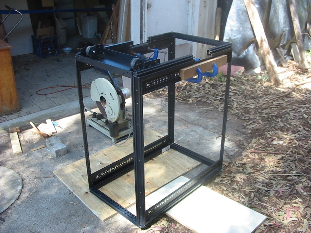
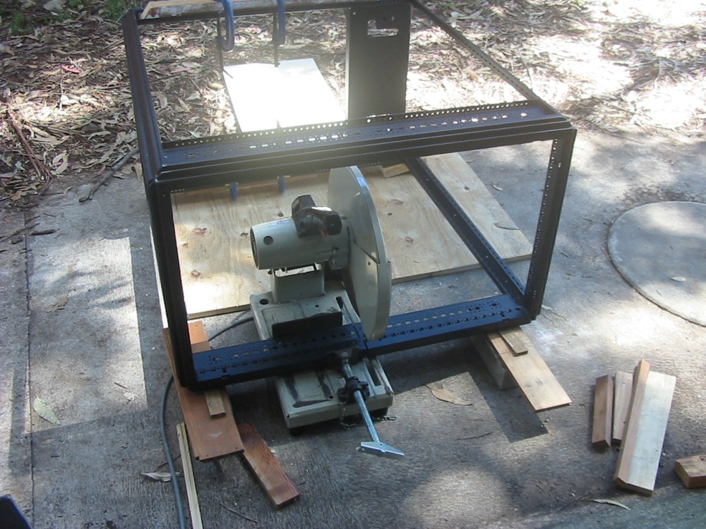
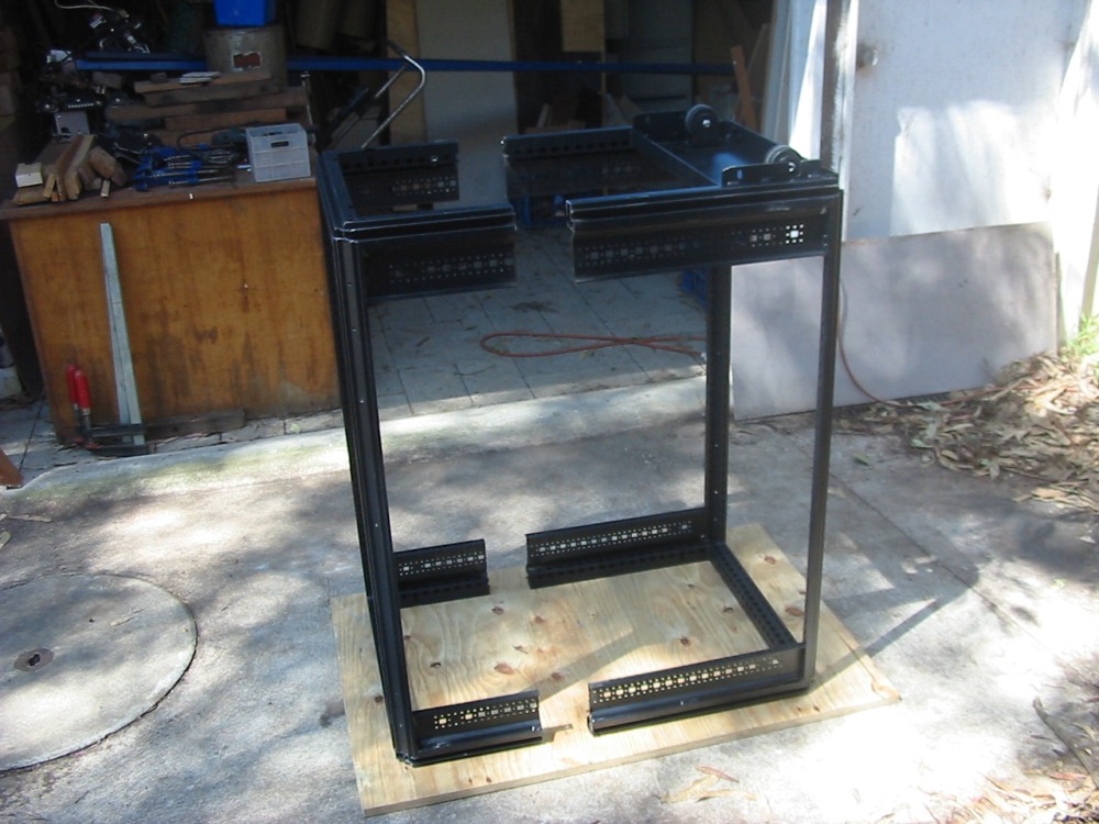
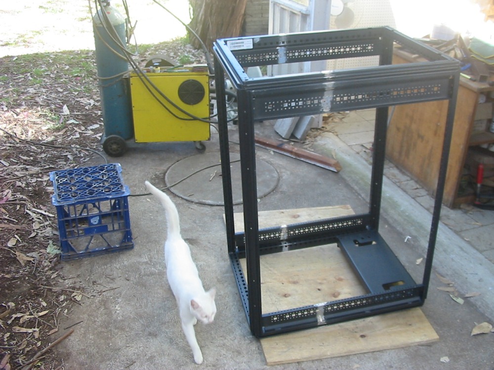
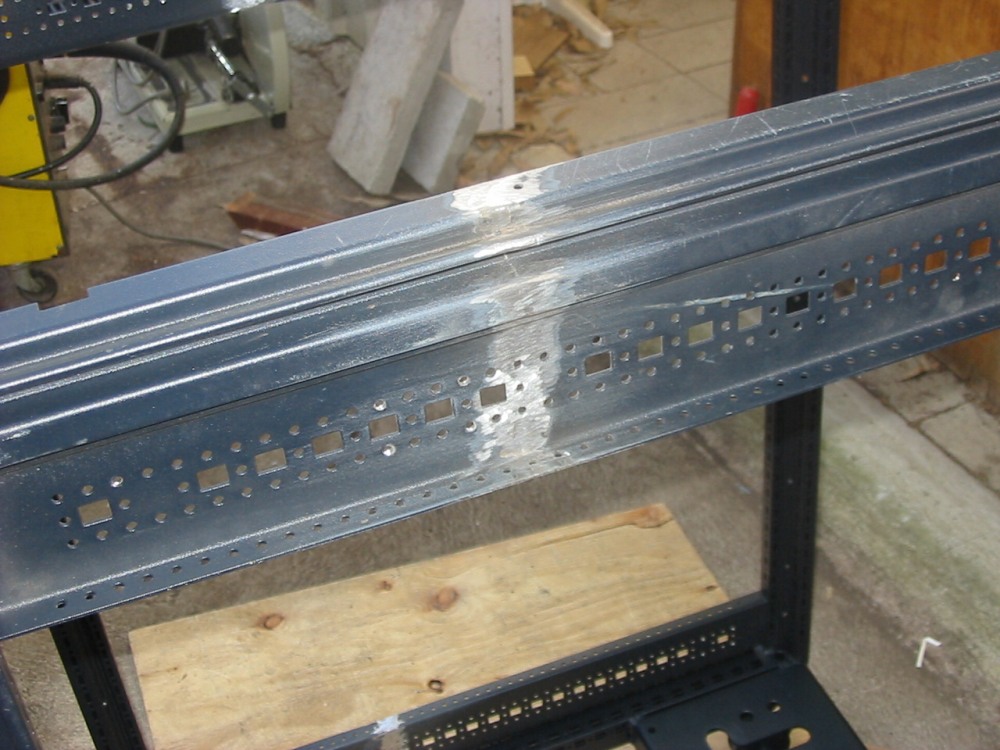
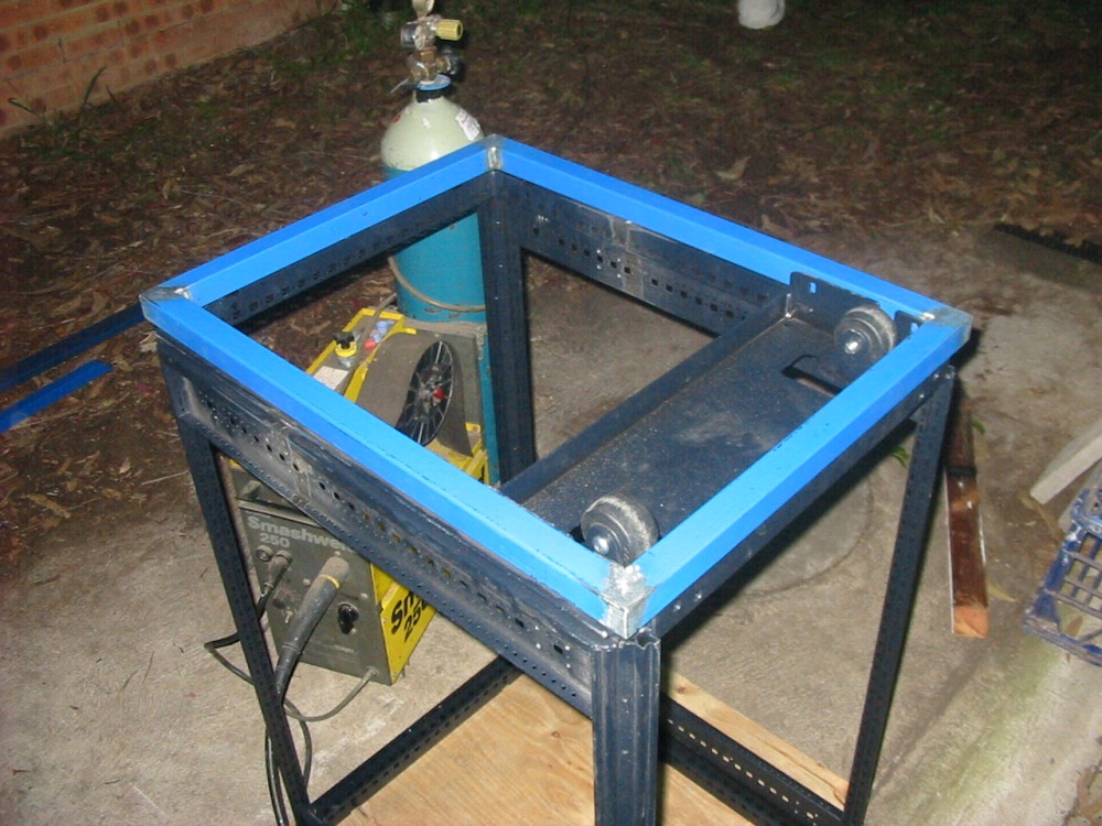
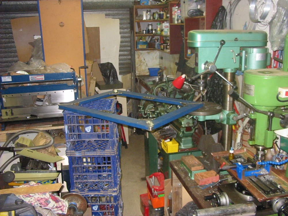
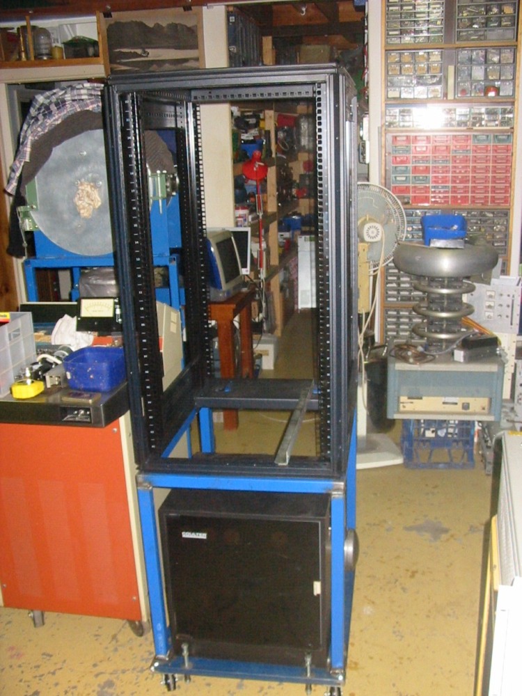
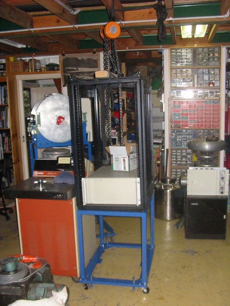
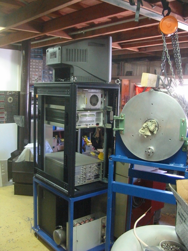
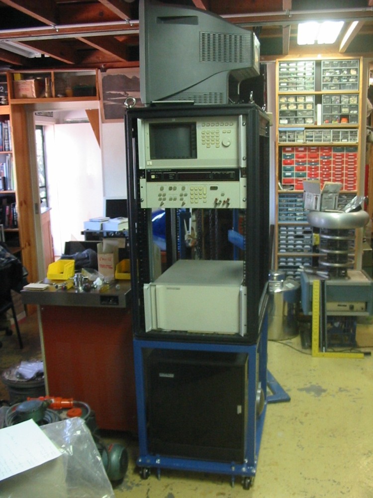
The rack and base assembled. At this point, when I tried to start mounting gear in the HP rack another problem with this rack became apparent. For equipment slides I have simple L shaped rails. (There's one visible in the 1st pic.) These bolt to the side frames and each instrument in the rack slides on two of these. Except that on this rack the distance between the inner mounting struts is too great, so typical 19 inch rack gear can fall down between the slides.
It takes me a while to come up with a fix for this. Eventually all I can think of is to pad the gap with small square tubular steel sections. But the horrible side of this is, if I want to be able to freely adjust rail heights the way rackmount gear is supposed to allow, then these tubes must have holes drilled for every cage nut hole in all four side rails. Worse, they all have to be precisely drilled, since if they are not, instruments sitting on the rails bolted via those holes will be out of kilter.
Sigh. That's a lot of holes.
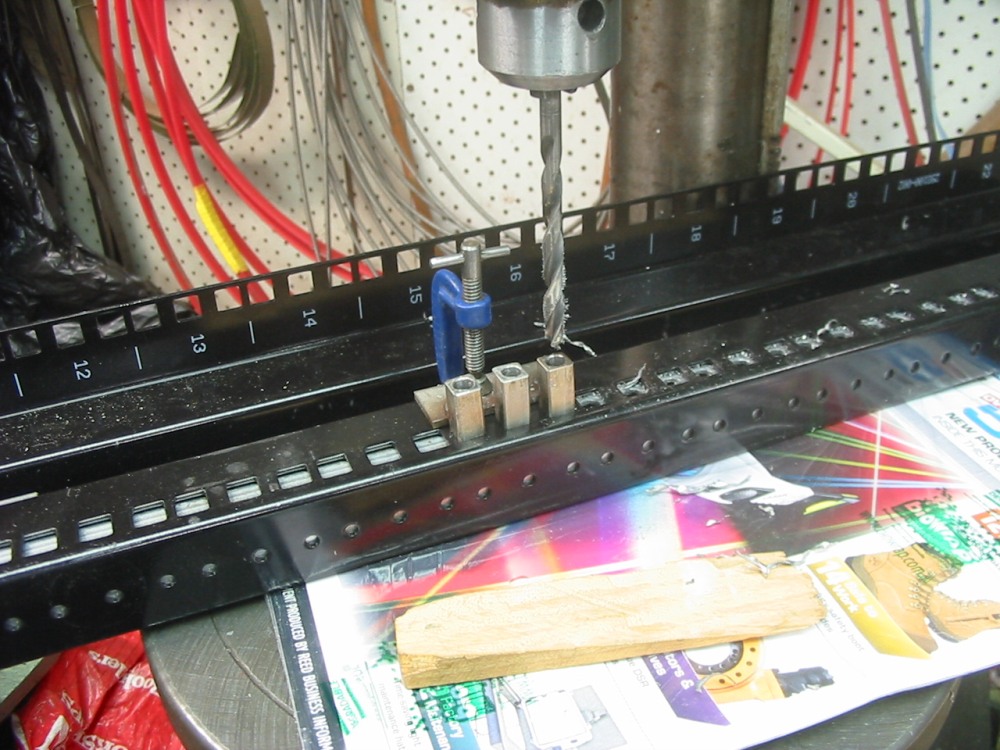
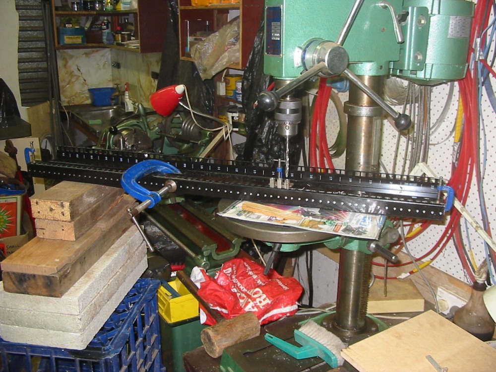
At least there's one plus - the rails themselves can be used as drilling templates. Only their holes are rectangular (for the cage nuts) and bigger than the holes must be.
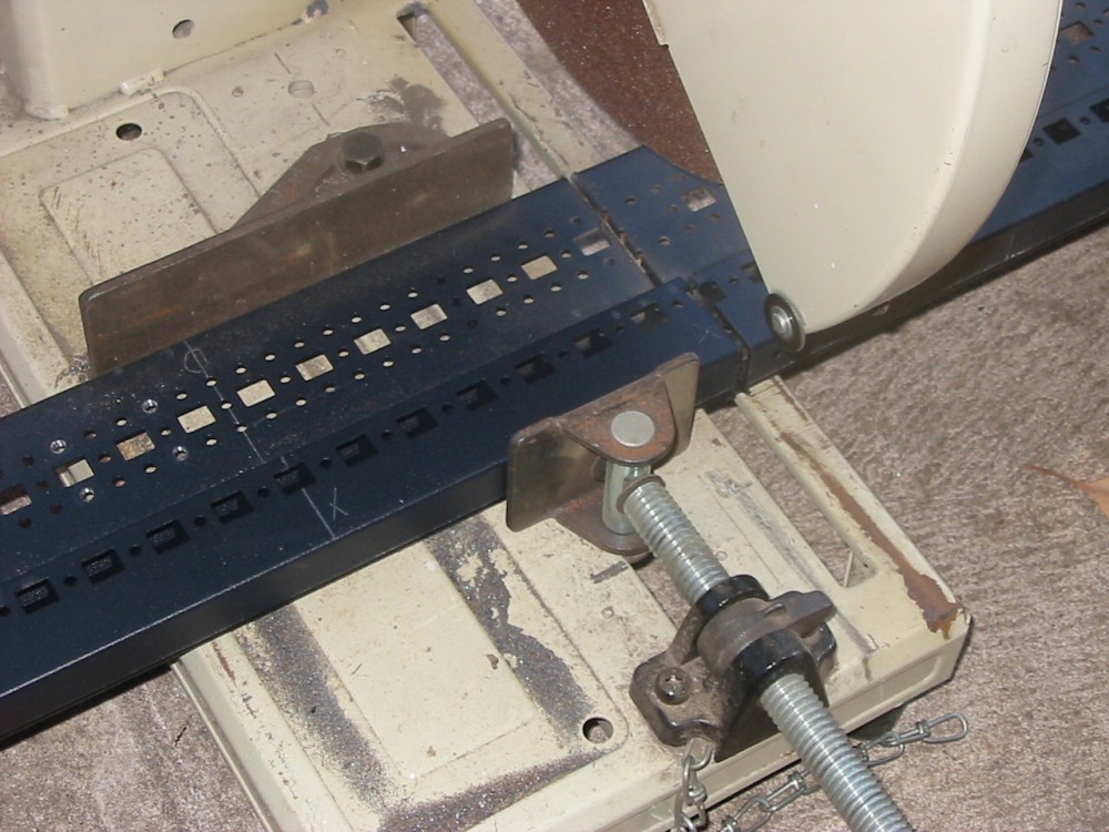
The solution was to make a drilling jig. Made of stainless, it clicks into place in each group of three equal-spaced cage-nut holes.
It was still a lot of drilling. Worked though.
|
|
|
|
|
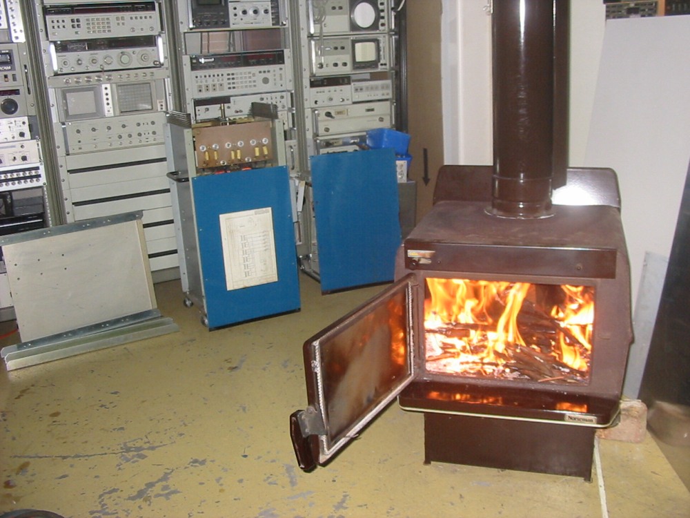
Meanwhile, the slow combustion fireplace I'd put in my workshop back in August this year had been mysteriously not working properly since the first few times I used it. Finally, in the last few days I'd figured out that the mesh I'd put in the chimney cap had mostly blocked up with soot, despite being quite large diameter. Getting up to there to remove it had been difficult enough that I'd put off doing it for a while. Now it's gone the fireplace is working very nicely. Just in time for the end of winter, ha ha.
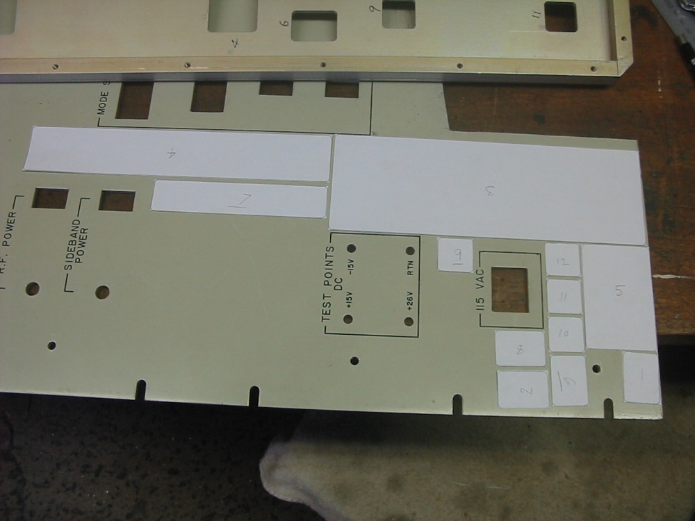
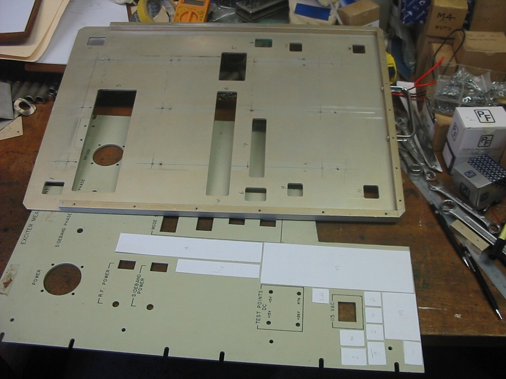
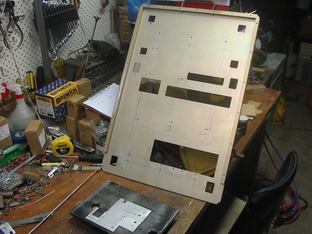
I'd also begun work on fixing up an old sliding rackmount shelf, for use with the PC, keyboard, mouse and monitor which would live in this rack. The biggest problem being that the aluminum tray has a lot of holes and cutouts that I didn't want. In the pics above I was working out how to cut the needed blanks from a sheet of scrap aluminum.
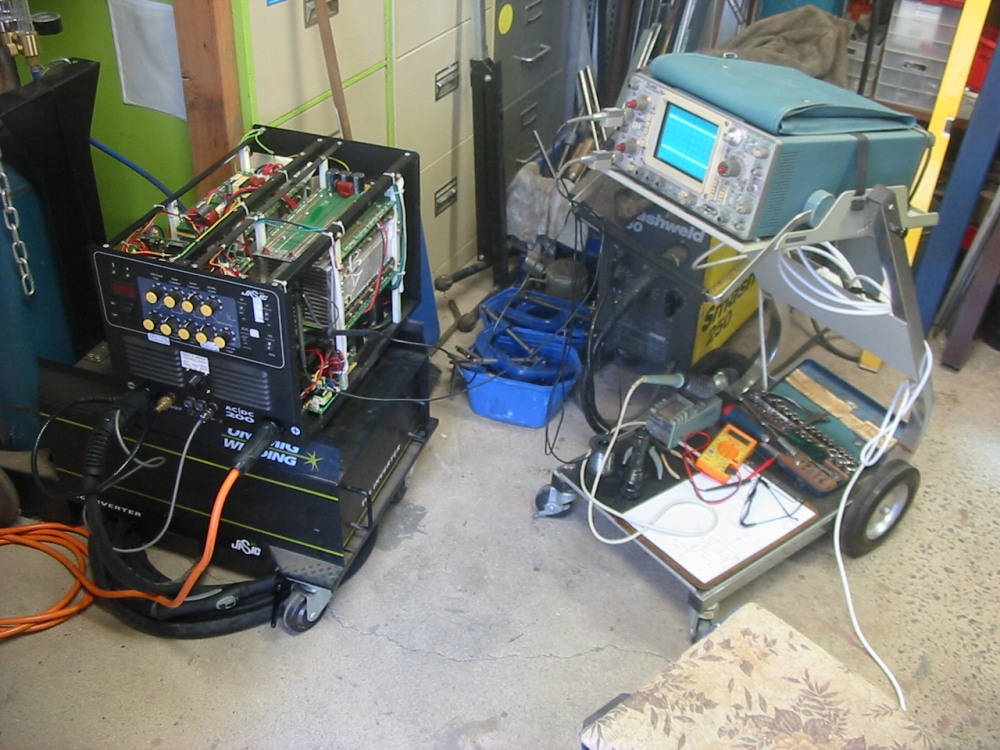
Then while preparing to tig weld the aluminum panels to patch it, I discovered my TIG welder seems to have developed a fault.
|
|
|
|
Continued in Recent work on the experimental area