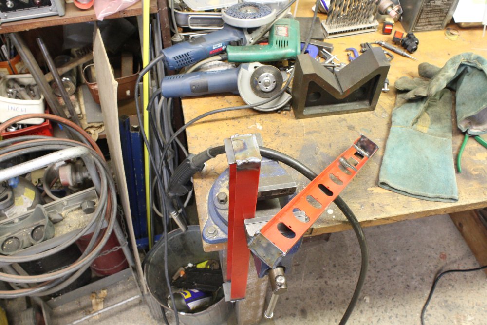
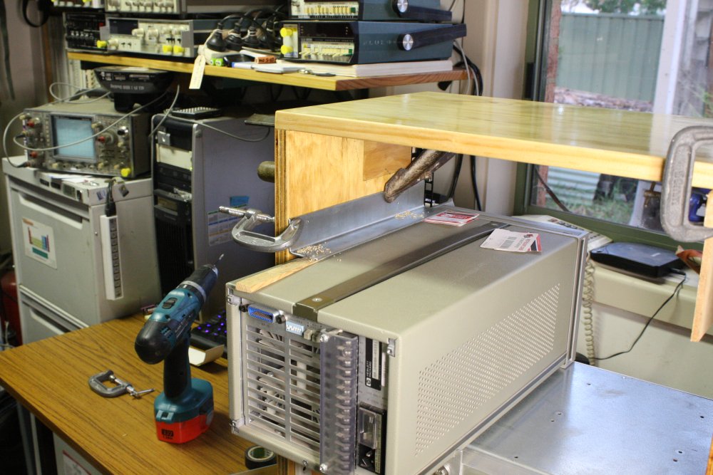
Here's another small workspace improvement project, in the vein of Spring Diversions and Vacuum Mashup. This one achieved the ideal: simple, fairly easy, quick, zero cost, and made a big improvement.
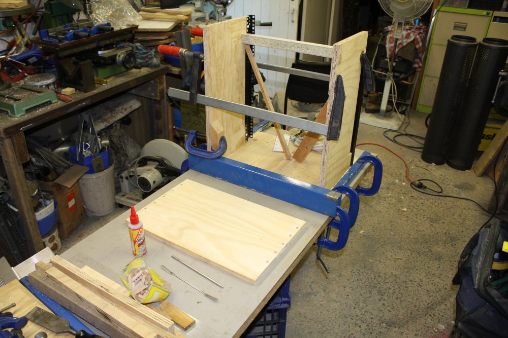
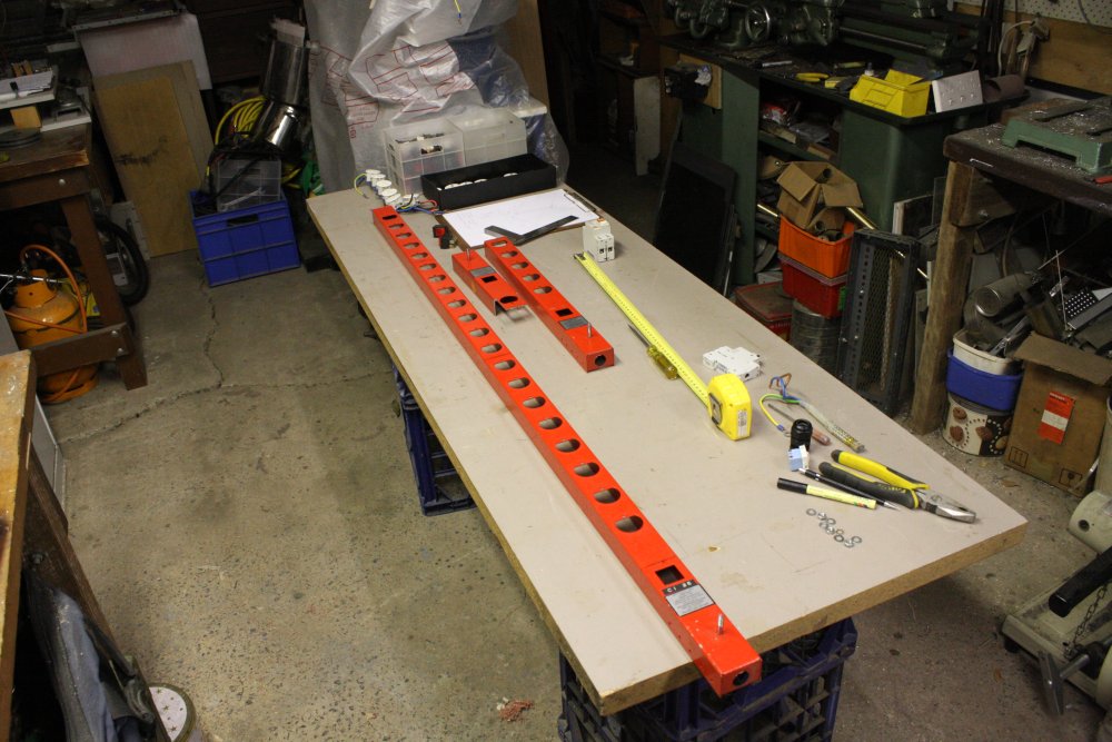
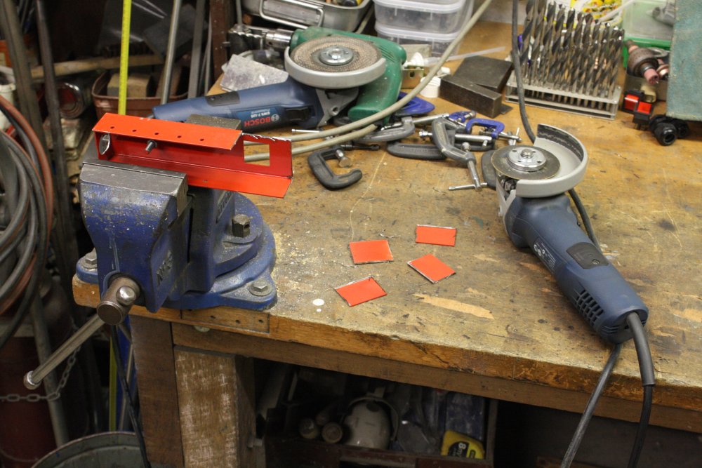
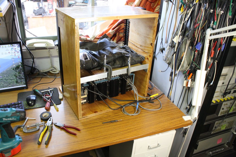
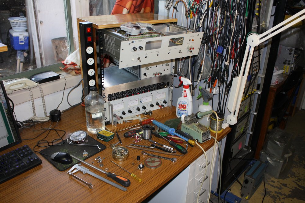
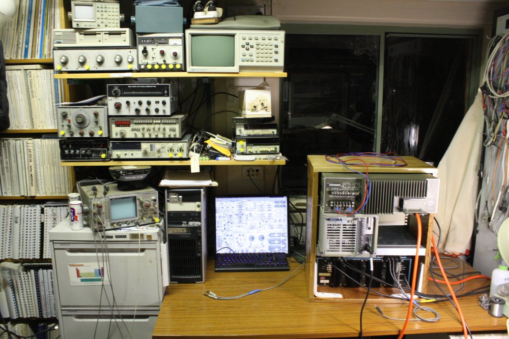
There are plenty of faults in this picture, one of them being the pile of stuff on the right hand side of the bench.
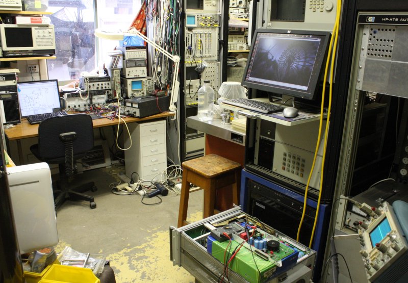
It occured to me, why not put a small 19" rack here? Only, one with no wasted volume, since it's a small desk and space is precious.
Nice idea, but with a minor problem - I don't have any suitable small racks. Worse, on going through the junk pile it turns out I don't even have any useful rack strut lengths anymore. Used up all the ones I had on other constructions last year.
But surely, it should be easy to find a small rack or just some more rack struts? I've seen so many old racks being junked in recent years, there must be plenty around.
Well, no. Buying one new is out of the question, they are always expensive. A place nearby that used to sell 2nd hand racks turns out to have gone out of business. Asking on the eevblog forum had no result.
I tried asking on another forum, and that worked. Someone sent me a couple of 535mm long struts from Melbourne, for free. Thanks Luke.
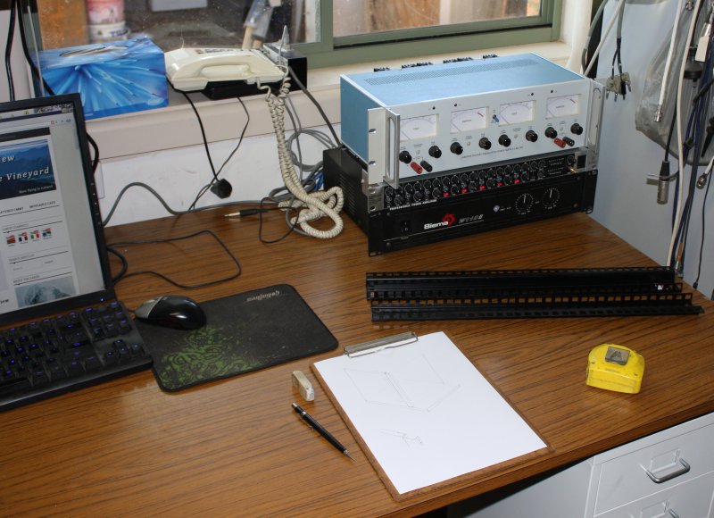
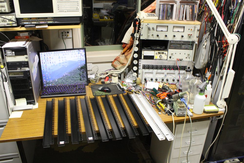
How to turn these two pieces of metal into a complete rack? (Without spending anything, of course!)
Do I look like a guy with a plan?
While I'd been waiting to find some struts I'd made the rack brackets on the blue power supply above. Started with a couple of old-style Hewlett Packard brackets, and machined them a bit to suit.
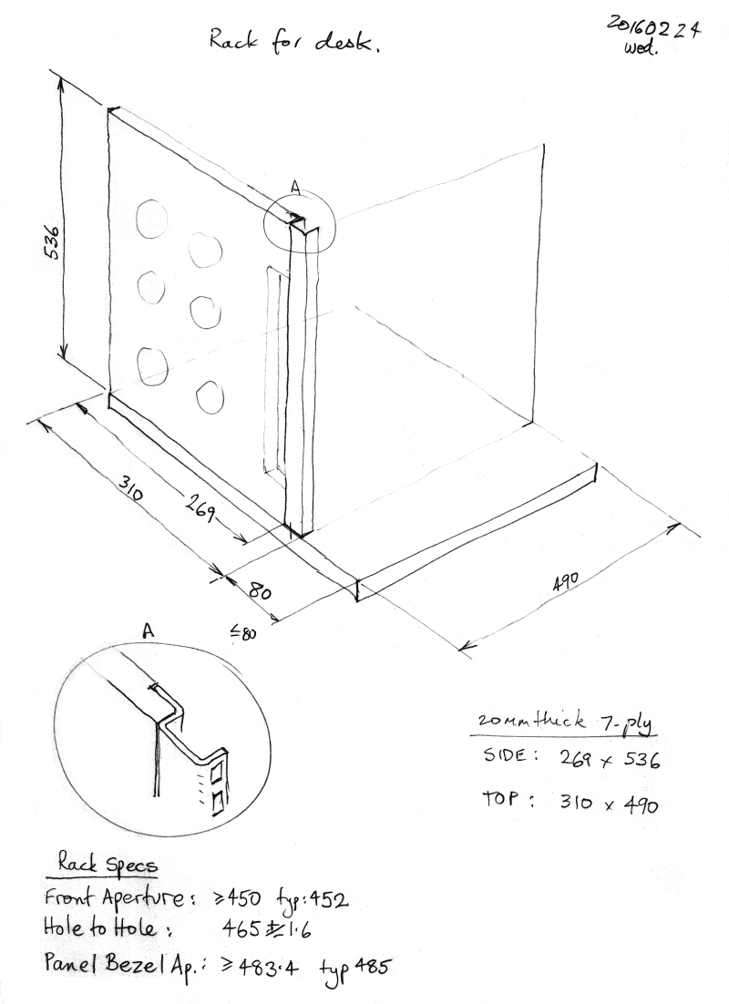
In my timber offcuts pile I found some sheets of 20mm 7-ply, which looked like there would be enough for the two sides plus top and bottom of a frame.
 |
 |
 |
 |
 |
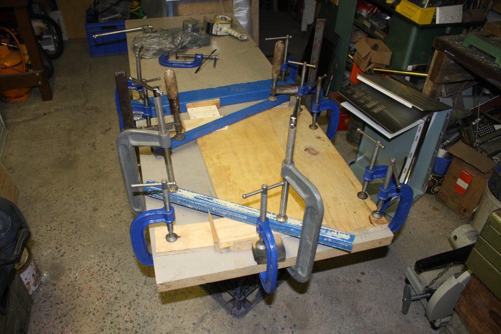
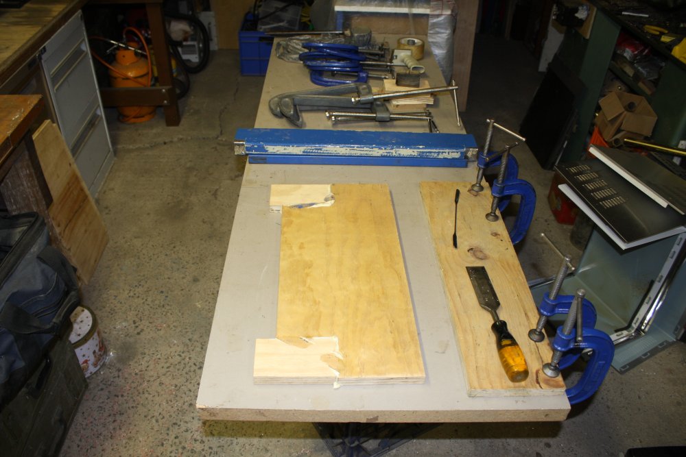
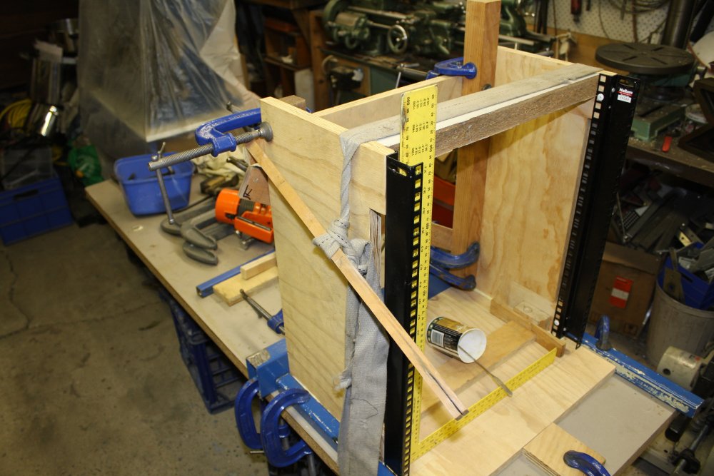
1 - 3. Naturally it wasn't quite enough. Or rather, two of the pieces turned out to be juuust a little bit short of the sizes they needed to be. With a side piece I fixed that by gluing inserts to extend the size where needed.
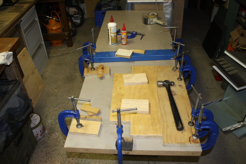
4. Routing to fit the edge of the rack frame.
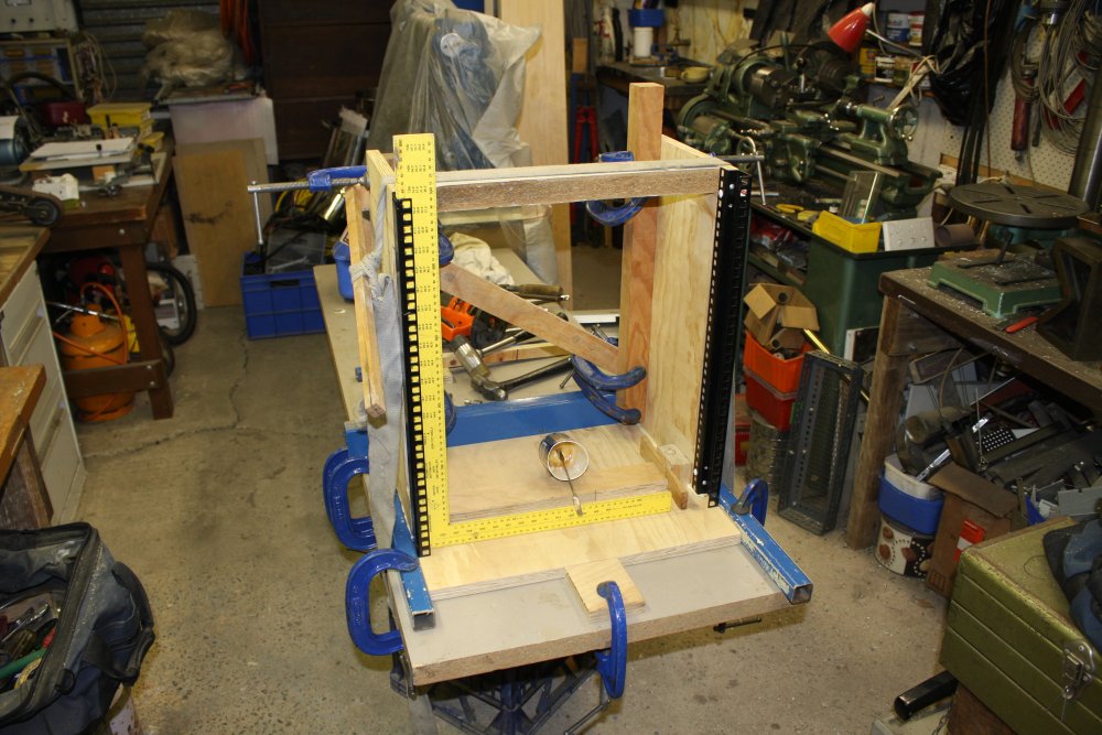
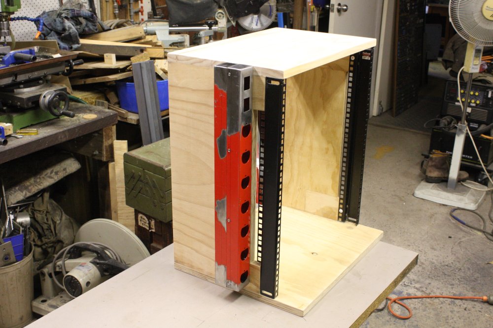
5. Trial assembly. Not glued yet.
 |
 |
 |
 |
 |
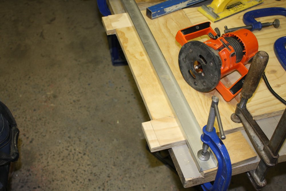
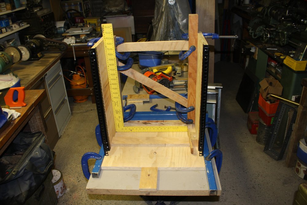
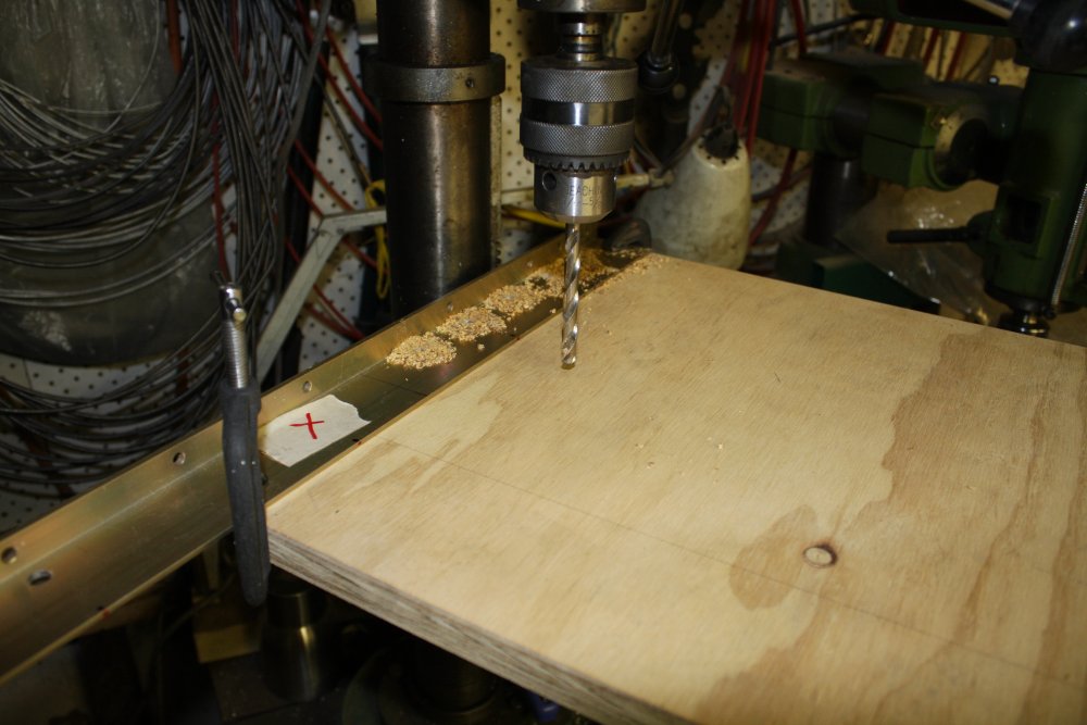
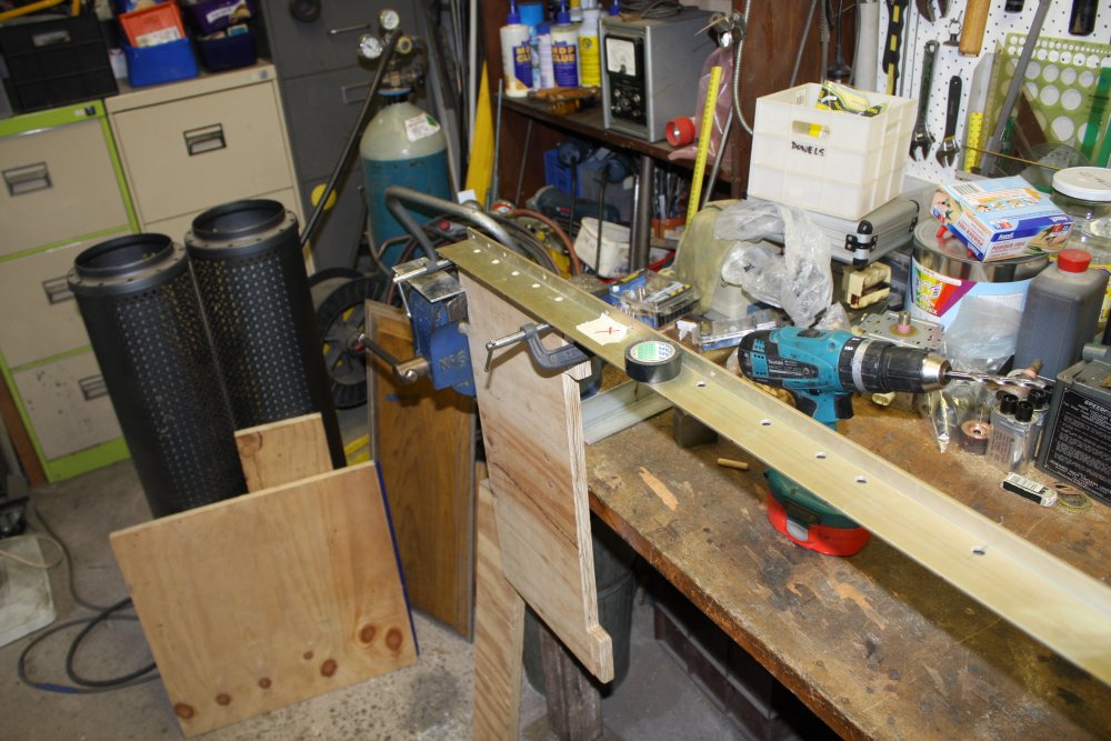
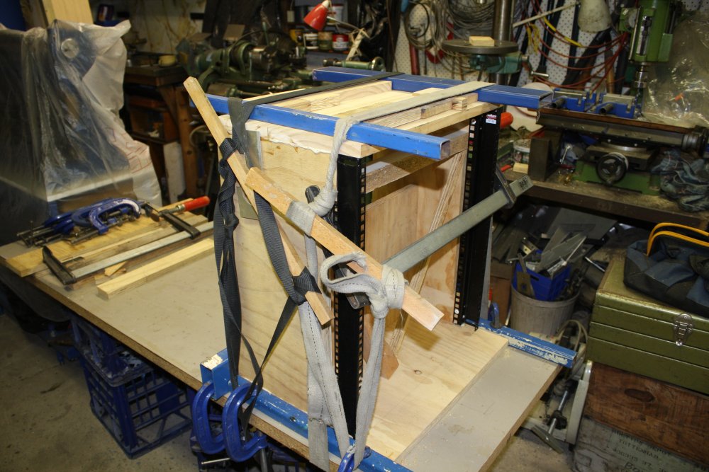
1, 2. The corner joins need to be dowelled for strength. Here using a template rail to ensure the holes in mating edges actually mate.
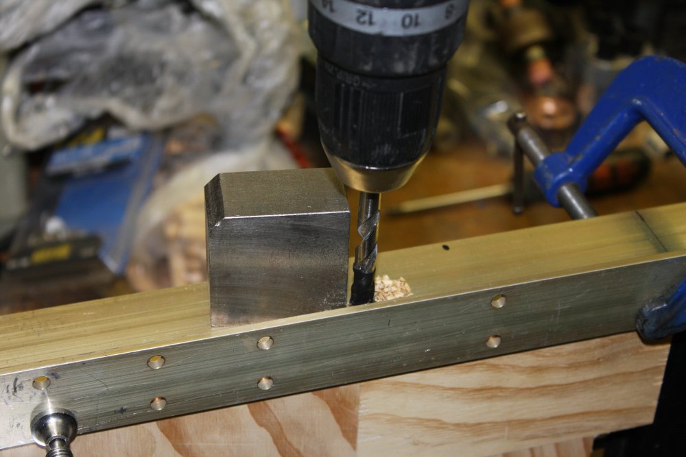
3. When the workpiece is too big to fit in the drill press but the holes have to be reasonably accurately perpendicular, using a block like this to give a visual reference for 'vertical' helps a lot.
4, 5. Gluing the sides to the base.
 |
 |
 |
 |
 |
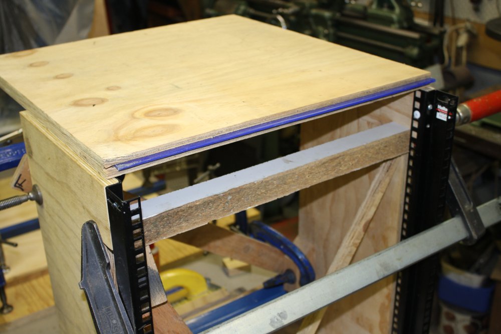
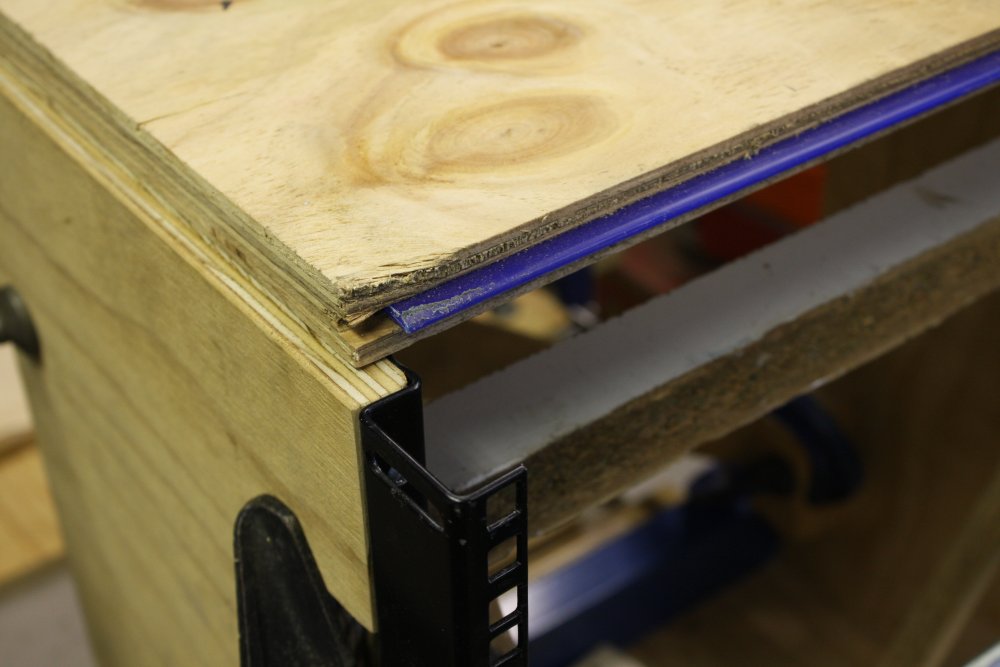
1, 2. Curses. The sheet I thought would do for the top, is about 5mm too narrow. Both ways. And since I want to be able to put heavy things on top of this rack, butt-gluing on a bit extra won't do. Hmmm...
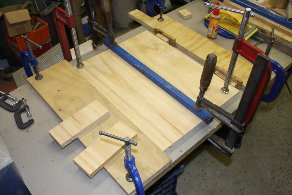
3. Lucky! A couple of pine plank offcuts left over from the machine shed shelving upgrade were perfect for this. Just needed to dowel and glue them together (in this pic) to form a plank wide enough.
4. All ready to glue on the top. All the dowel holes drilled, ready to go.
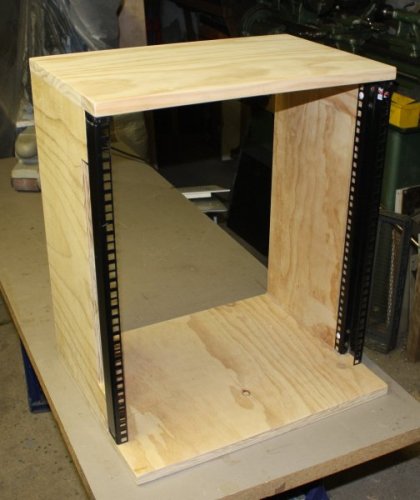
5. Glued and clamped.
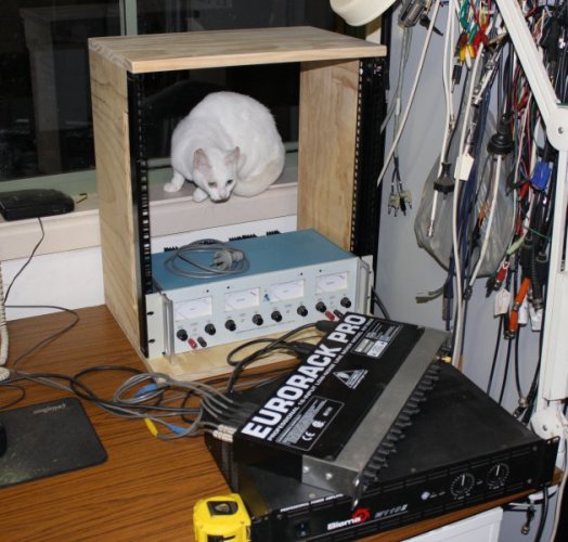
An immediate object of fascination for cats. Does it have box-nature?
It's not finished yet. I'm going to put a power outlet strip on the left, with a master switch, so I can shut down everything in the rack with one action. Partly this is inspired by the annoyance of my audio amp and mixer units having power switches at opposite ends of their front panels. This gets pretty tiresome after a while.
There may also need to be slide rails for some units. As for bracing, I'd originally planned to put crossed wire braces on the lower part of the back. The upper section I want to keep clear, since the window frame behind this allows for some extra depth equipment.
However the frame turned out very rigid and probably doesn't need cross bracing. (So long as I don't drop it on an edge.)
Plus I haven't yet decided if it needs ventilation holes cut in the side panels.
Once all the fiddly bits are done, it will be lacquered.
20160324
Wait, did I say this project was 'quick'? Typical. Almost finished the bare box, and he's so sure the job is nearly done, he puts a <hr> in the writeup. Will I never learn?I forgot about the 80:20 rule, or whatever it is - can't even remember what it's called! Anyway, 80% of the work is usually in the final 20% of 'finishing'. Yes, there were a 'few things' remaining to be done, plus the usual Life priority interrupts and sidetracks... It's been nearly a month since I wrote the text above the line, but now it's finished. Here's the process.
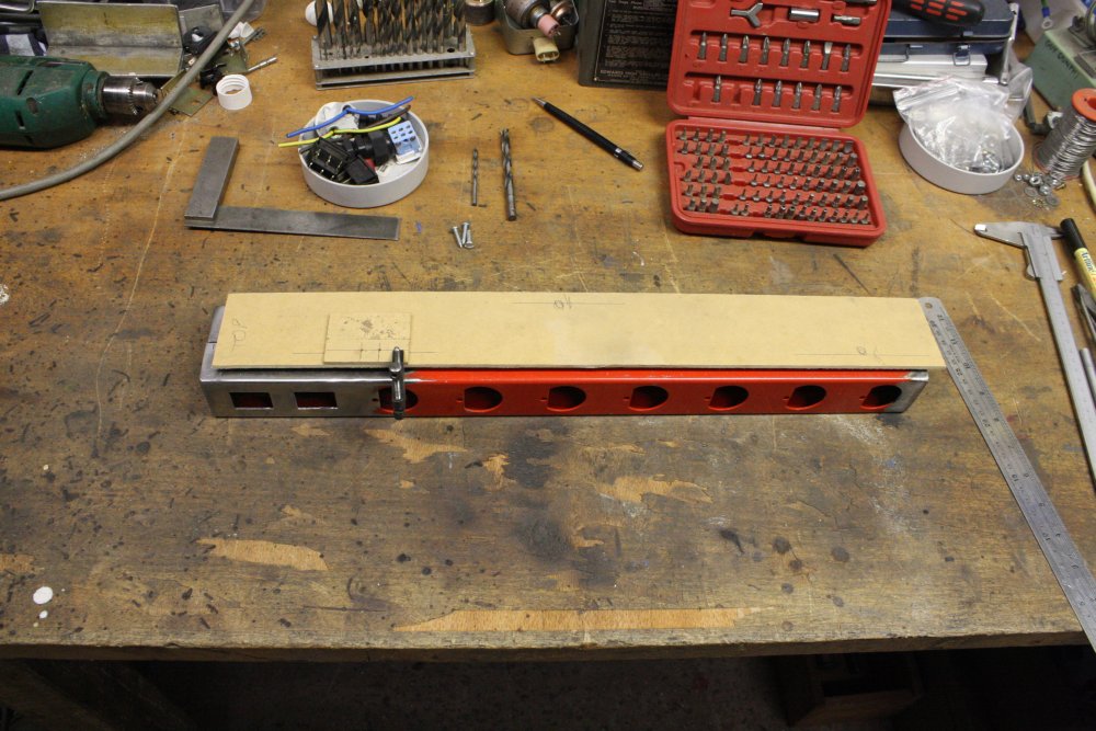
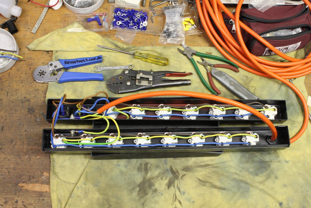
First the power strip. Not just some ordinary plastic thing, no, I wanted a fancy one. Or rather, with one set of outlets facing the back (for things in the rack), and another set facing forwards (for things on the desk), each set with its own switch. Of course this means making it. Like so...
 |
 |
 |
 |
 |
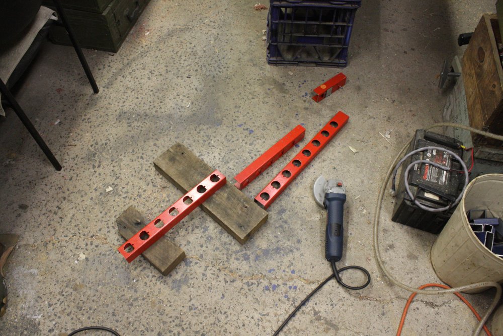
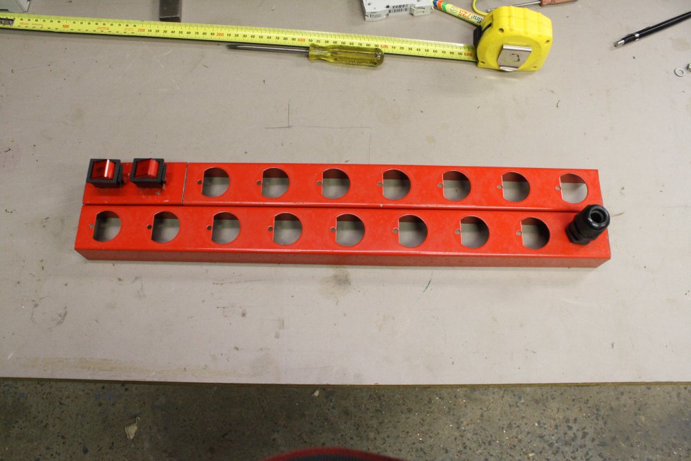
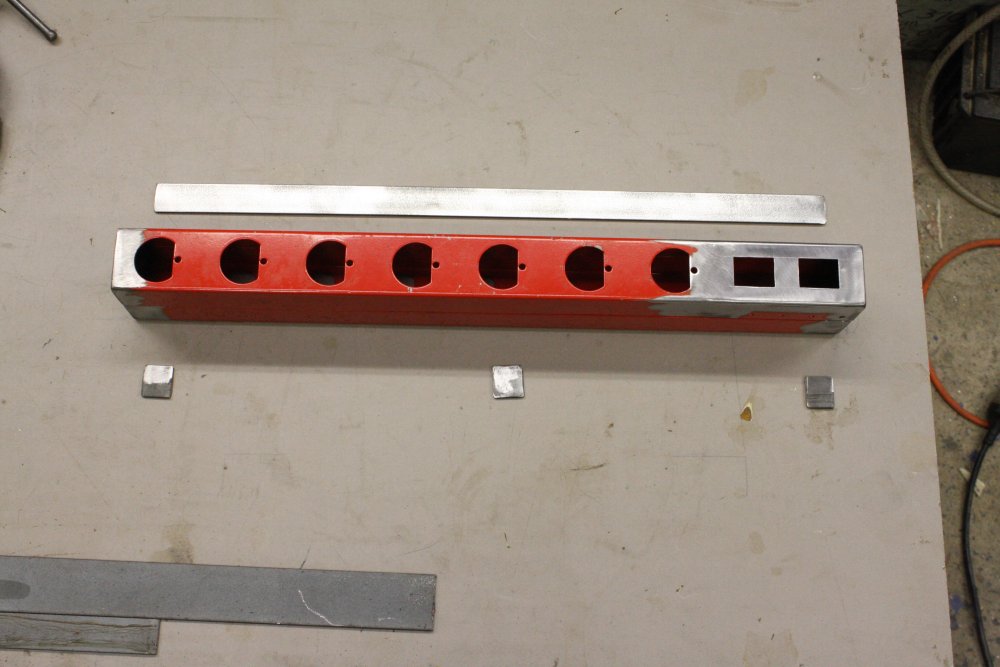
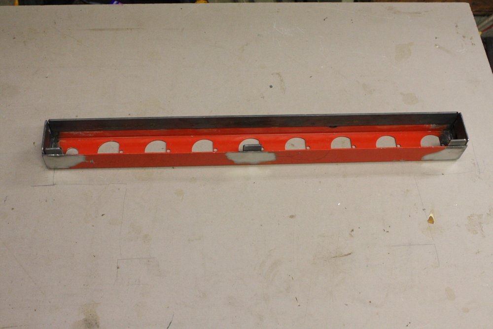
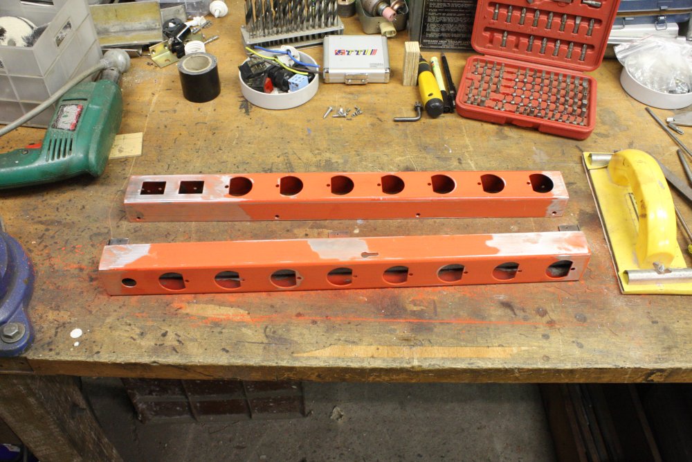
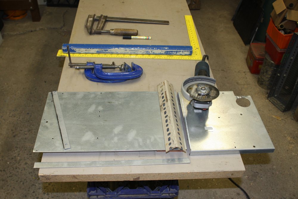
1. Fortunately I had another of these long power blocks from an old rack. Since they have no back cover they are unsafe for general use, but they are a good start when constructing a custom power board.
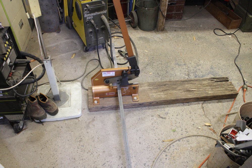
2. Cutting the lengths I wanted.
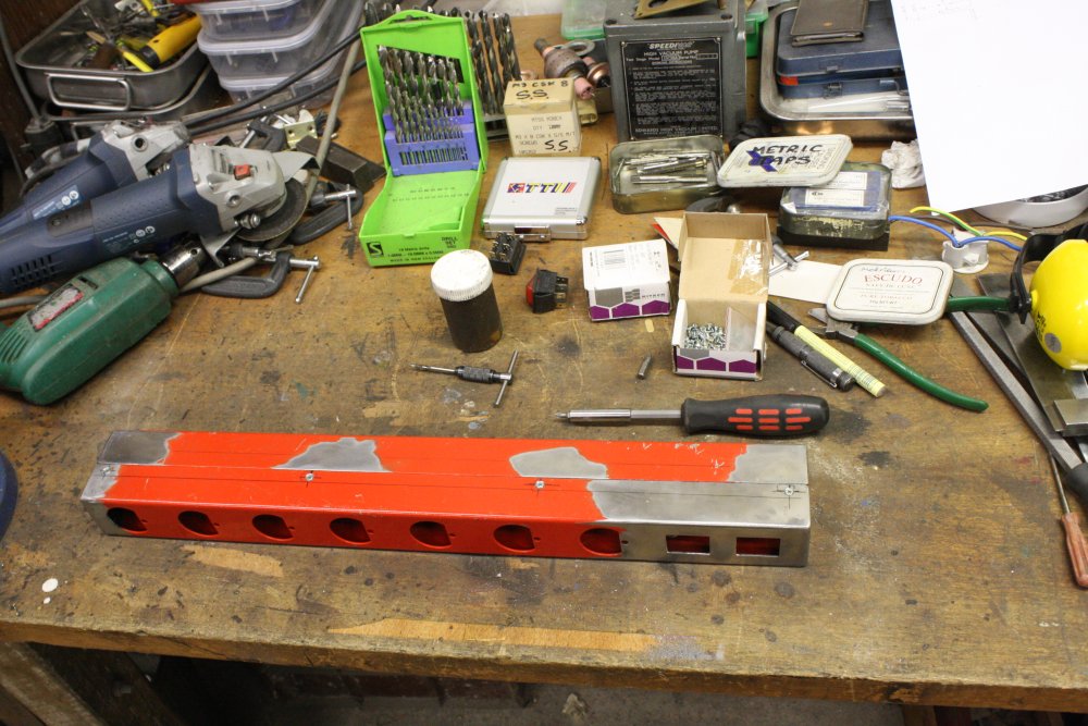
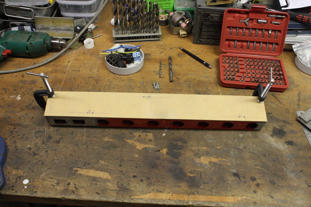
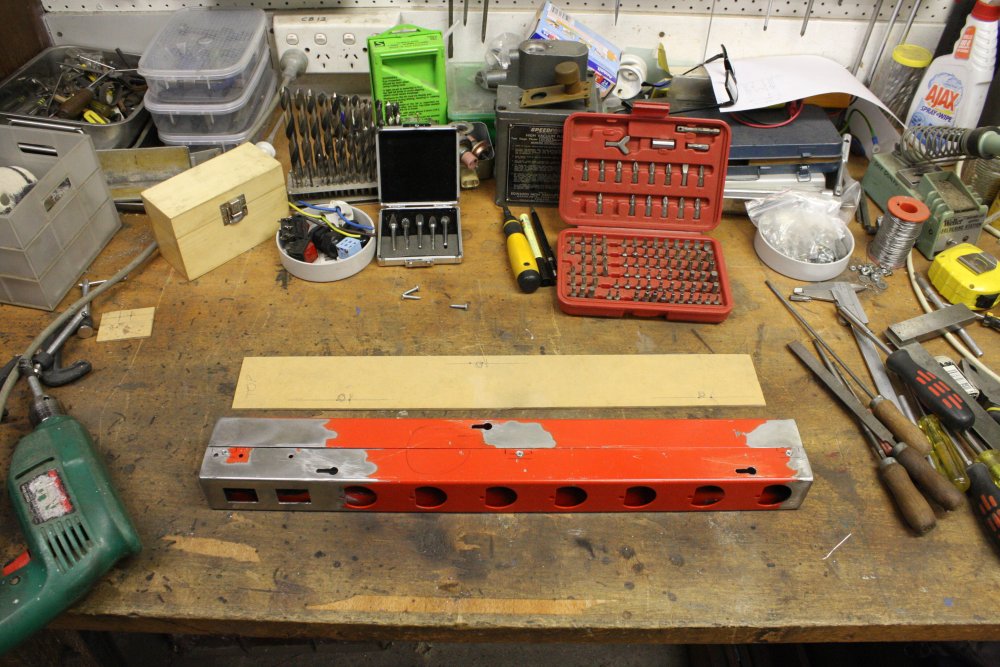
3. Laying out. No paper plans for something this simple!
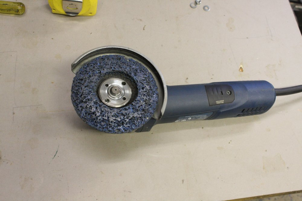
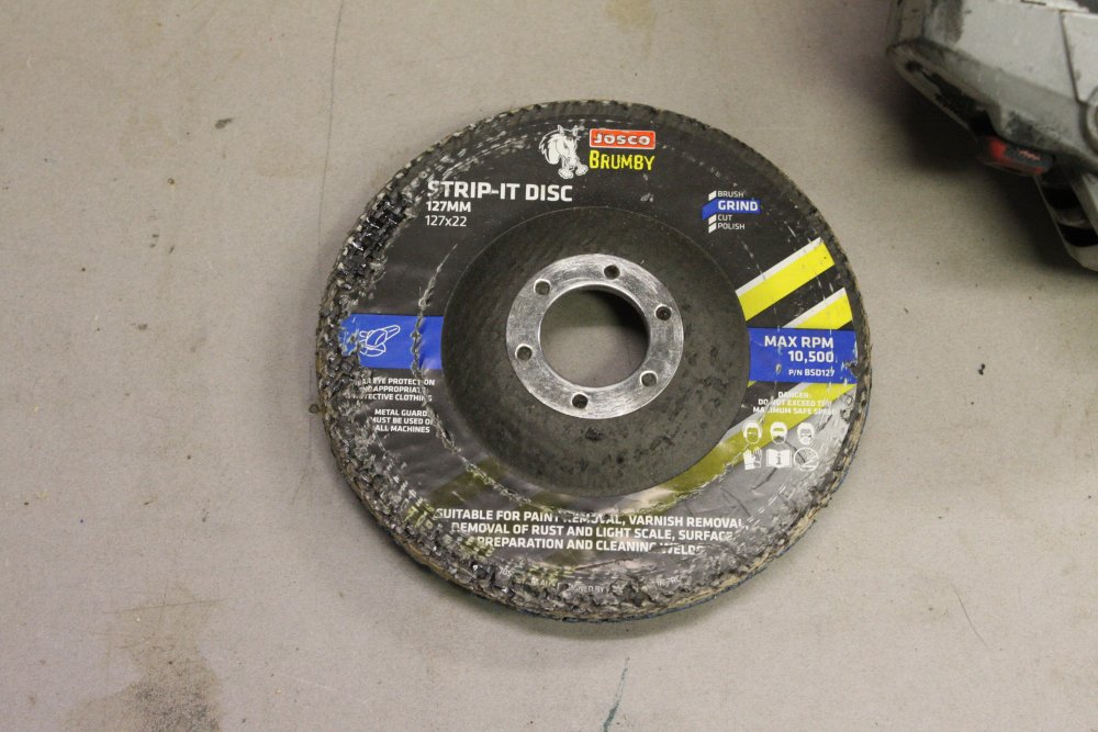
4 - 5. An aside. These paint stripping and steel smoothing disks are the best I've ever found, by far. They are excellent. So did I buy a lifetime supply? No, I didn't. This is the last one I have, and apparently they are no longer made. According to Bunnings, they were withdrawn/recalled. Why? I have no idea. Keep meaning to phone the manufacturer and ask, but keep forgetting due to being too busy. Really must. My guess: some other manufacturer with an inferior and more expensive product but a critical patent forced Josco to stop selling them. Because they are too good.
 |
 |
 |
 |
 |
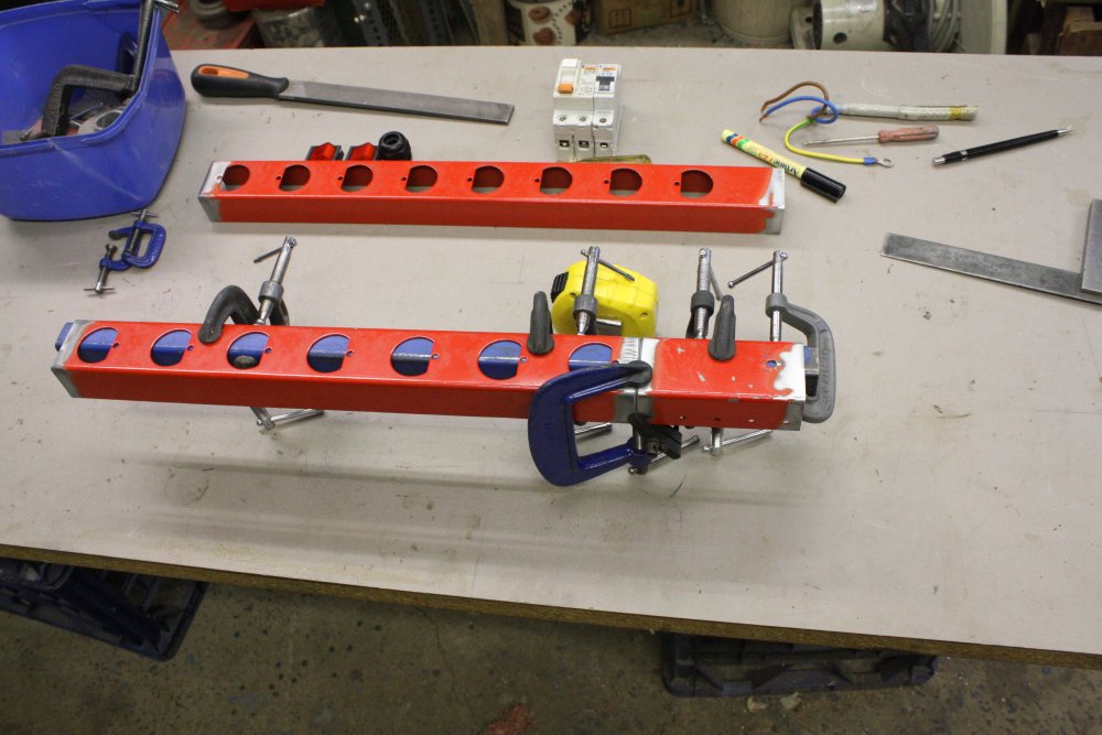
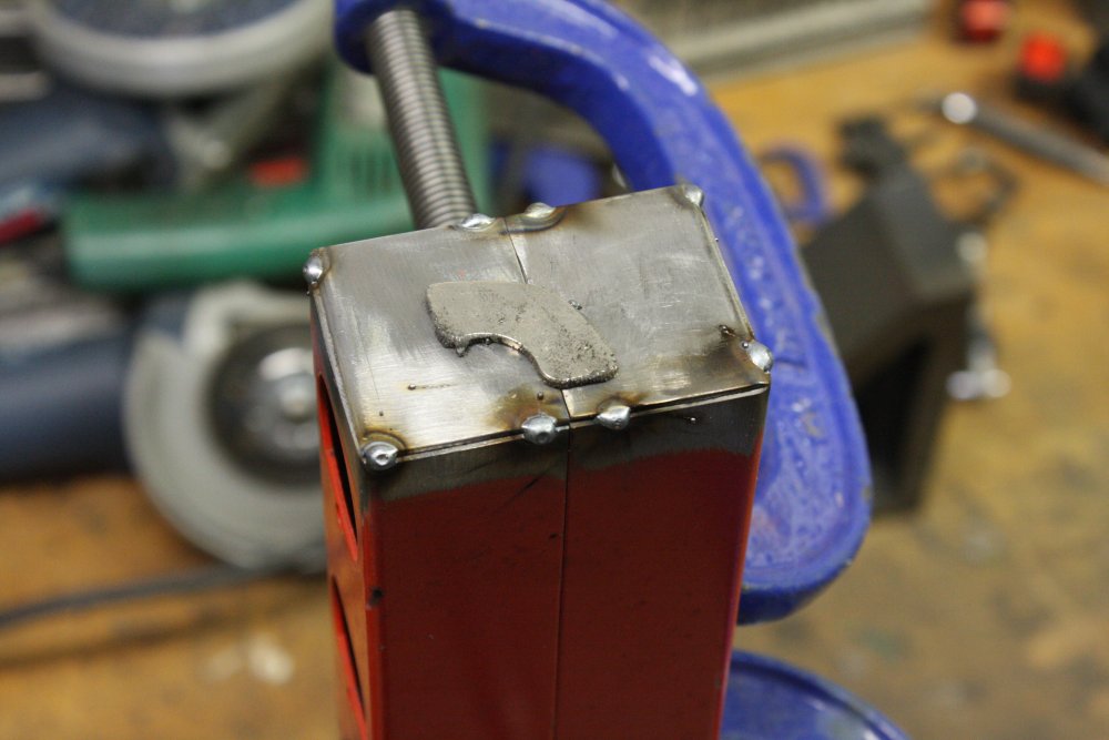
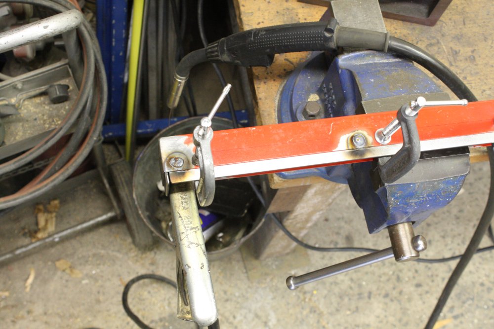
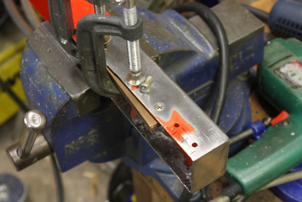
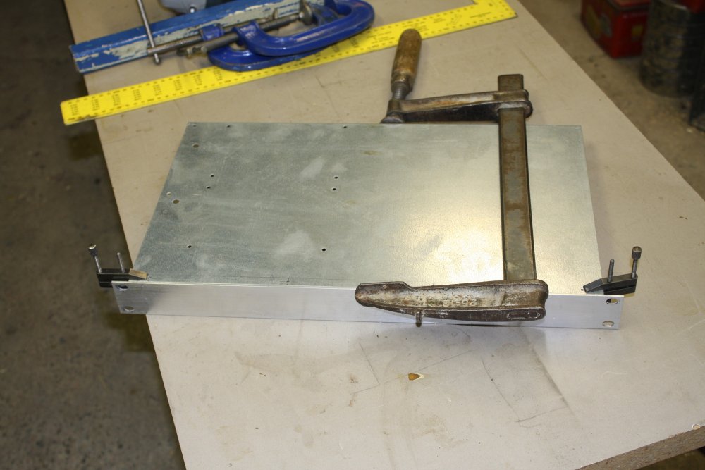
1. Clamping to weld on the blank bit for the switches. Note inner bar to ensure it stays straight.
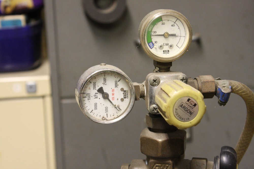
2. My Argoshield cylinder is aaaaalmost empty. Will it hold out for this job? I hope so.
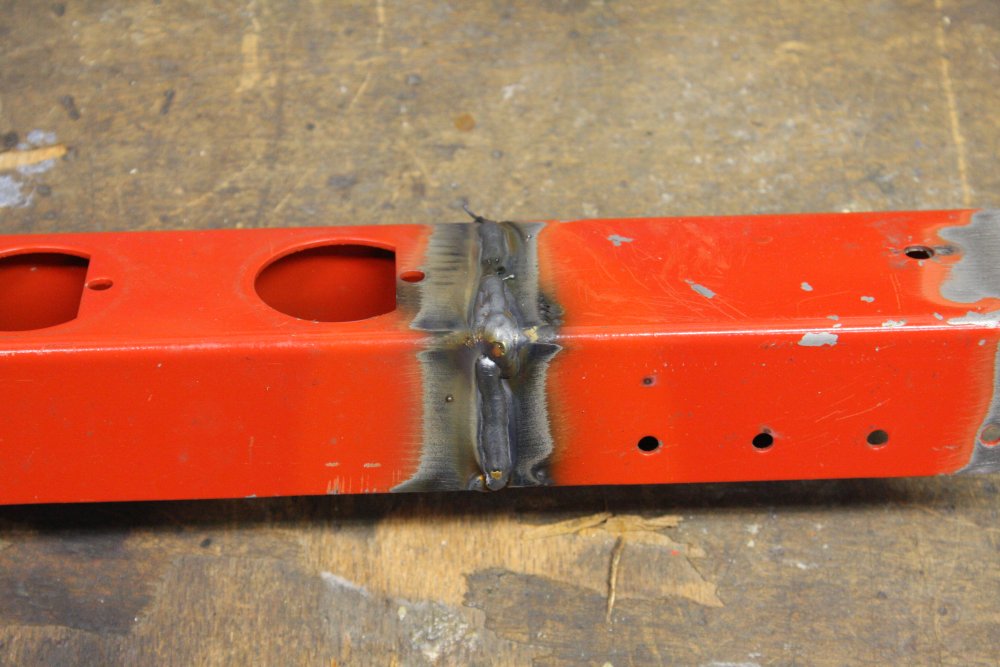
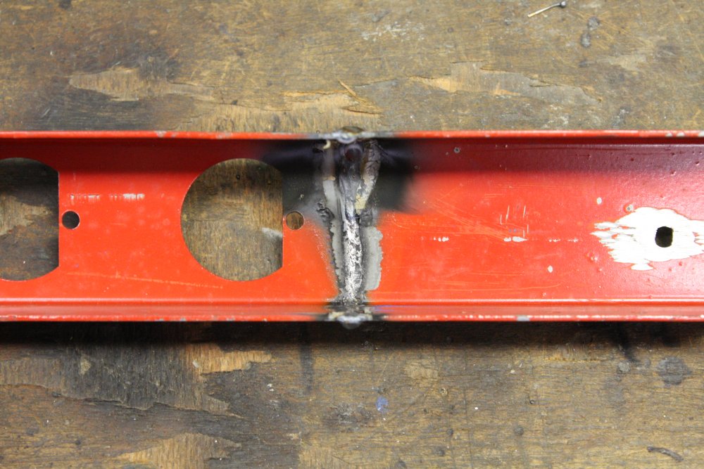
3. Crappy welds. As usual it doesn't matter since they get angle-ground flat later. So long as the penetration is OK, it's all good.
4. The penetration is OK.
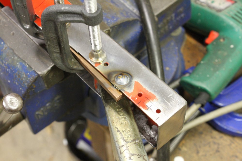
5. Weld ground down, now marking out the holes for the switches.
 |
 |
 |
 |
 |
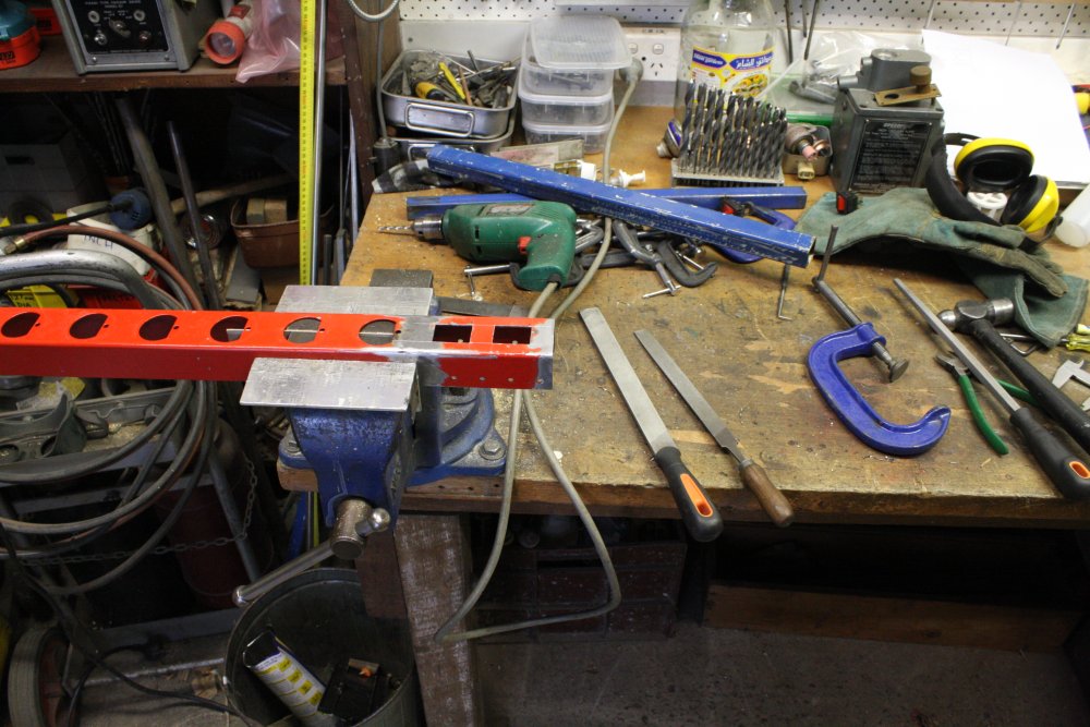
1. Holes cut. Not showing the messy intermediate stages - drilling small holes along a rough outline, mangling away the thin bridges between holes, then filing out to the scribed lines.
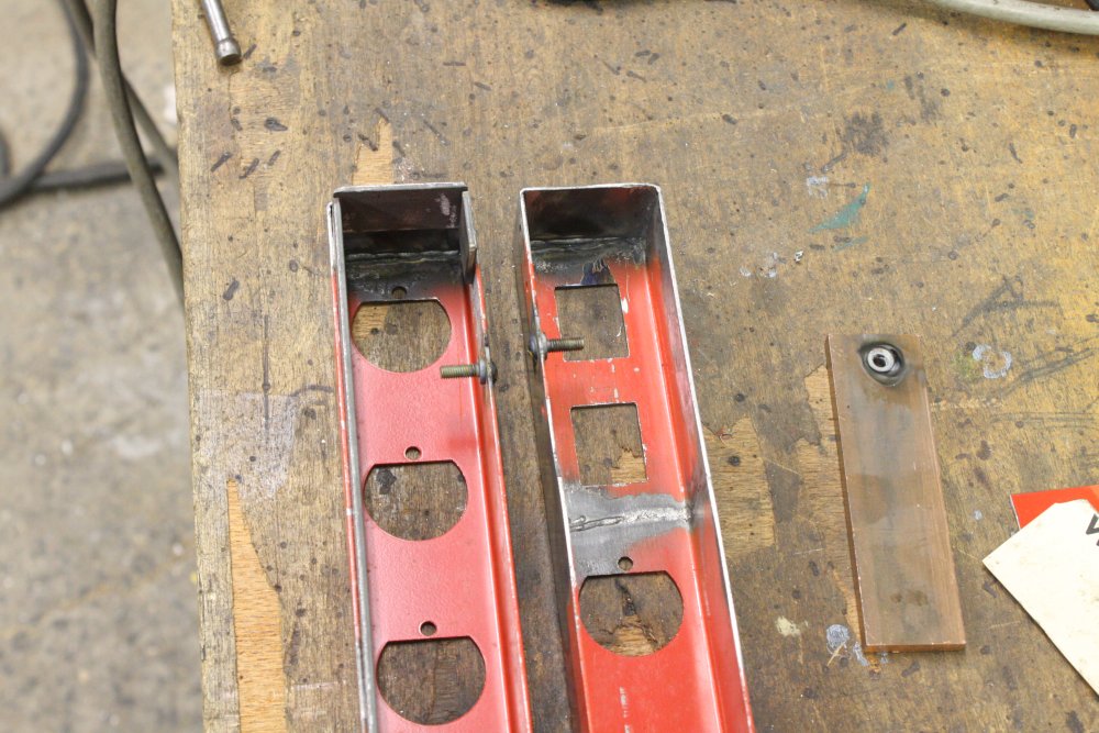
2. Lining things up for end cap welding.
3. Cutting the end cap pieces from a scrap section.
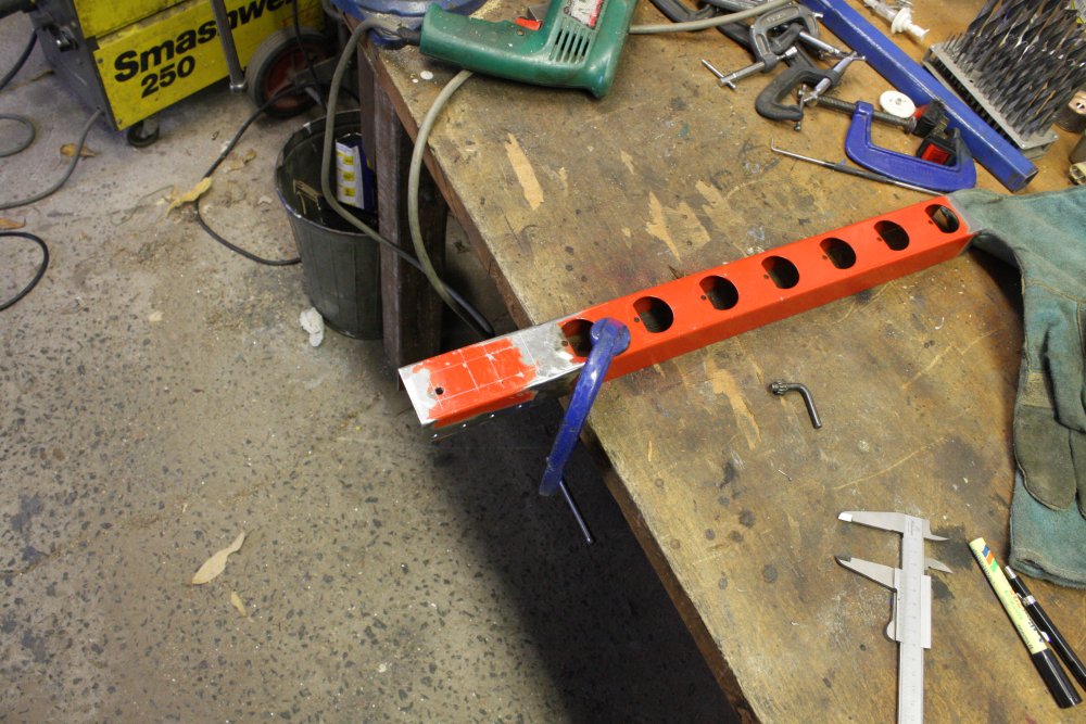
4. Luckily, the G-clamp ends just fitted through the holes.
5. Tongues welded on one side, with weld plugs already ground flat.
 |
 |
 |
 |
 |
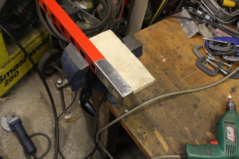
1. Settup. Magnets are so useful. Especially very strong ones from old hard disks.
2. Tack welds. Have to be sure not to accidentally weld the two sides together.
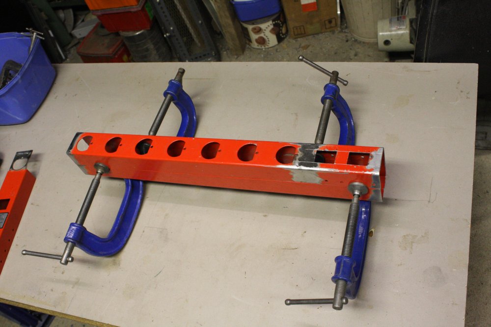
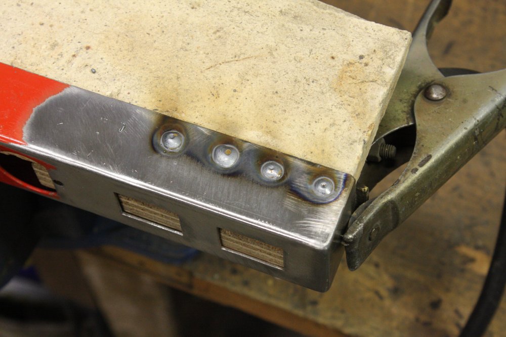
3 - 4. Ends welded on, welds ground down and smoothed.
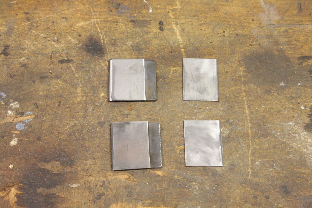
5. Cutting some strips for the case joins.
 |
 |
 |
 |
 |
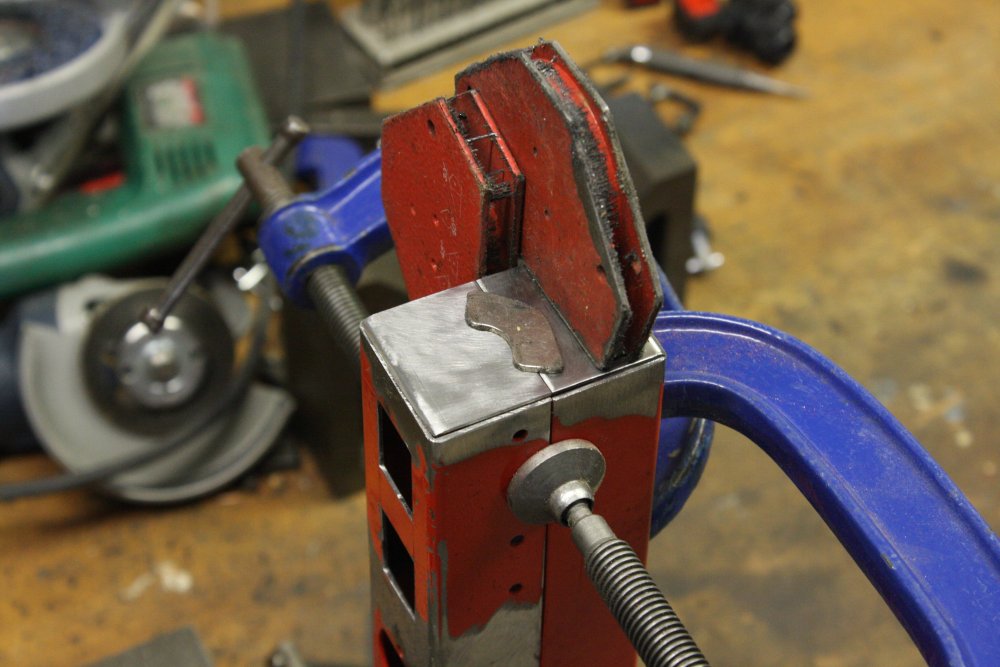
1 - 3. Fixing on the strips. These serve to align the sides, and also ensure nothing can be slipped into the interior of the mains power block via the seam. Annnnd... with almost no more welding to do, the gas cylinder hit empty. It's quite dramatic; one moment the MIG welder is going fine, then suddely you're welding with small firecrackers. The hot steel exposed to air is explosive. In pic 2, the leftmost weld is where the gas ran out.
The Argoshield is a mix of argon, nitrogen and CO2, while TIG welding gas is relatively pure Argon. I have a cylinder of Argon, and I'd thought the Argoshield mix only existed because it's cheaper due to the much reduced amount of rare Argon. So I swapped the Argon cylinder over to the MIG welder, thinking I'd continue with that for the moment.
Ha ha, no, I'm wrong. Argon totally doesn't work for MIG welding. The result is horrible. The arc sputters and blows around randomly, everywhere but where you want it to go. It sounds remarkably like blowing a raspberry. The MIG welder commenting on my lack of welding knowledge. Fair comment too. As a result of the arc being all over the place, the weld bead (such as it is) is too cold, with virtually no penetration melting of the substrate. You get just a bumpy pile of metal, barely adhering to the work. Fail. Looking it up on the net, I could have learned this before the bother of swapping cylinders, then having to put the Argon back on the TIG machine. I learn the small amount of CO2 in Argoshield mix is essential for 'stabilizing the arc', and thus transfering heat to the weld bead. Also that there are actually different grades of Argoshield, for different thicknesses of metal being welded. Mine is the 'light' version, for thin mild steel. There's one for welding much thicker steel, and others optimized for different types of steel.
Fortunately my account with BOC is currently not in arrears (this is unusual), and even more surprisingly I had enough cash to go do a cylinder exchange straight away. So it wasn't the show stopper it could have been.
4 - 5. Some holes from the original strips, that would show on the outer face when the thing is mounted. They needed to be removed. Easy, when you have a nice new, full cylinder of the right MIG welding gas.
 |
 |
 |
 |
1 - 3. Welding in earthing studs.
4. Fastening screws, threads tapped into the mating strips.
 |
 |
 |
 |
 |
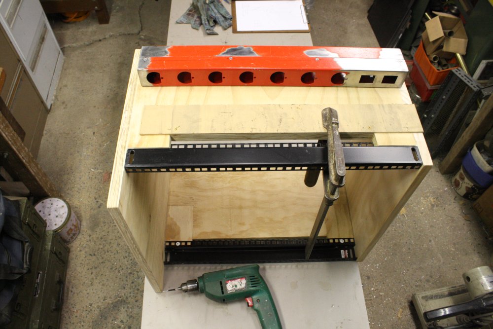
The whole thing is to clip onto the side of the rack using hole-slots, with round-head screws in the plywood. This requires the holes and screws be very exactly aligned. So it's template time.
1. A scrap of 3mm MDF is cut to the size of the power strip, then a small template is used to drill pairs of holes identically spaced, into the sheet. These represent the center of the 'big hole' (that the screw head enters through), and the end of the slot (that the screw shank rests against in final position.)
2. Then those holes are transfer-drilled to the power board.
3. And drilled out to full size, and the slot filed by hand.
4. The screw position holes are transfered to the side of the rack, using the template.
5. Test assembly. Fits perfectly!
 |
 |
1 - 2. Sanding the remaining old paint rough then spray painting it black. Also the rack wood is given a couple of coats of clear urethane lacquer.
 |
 |
 |
 |
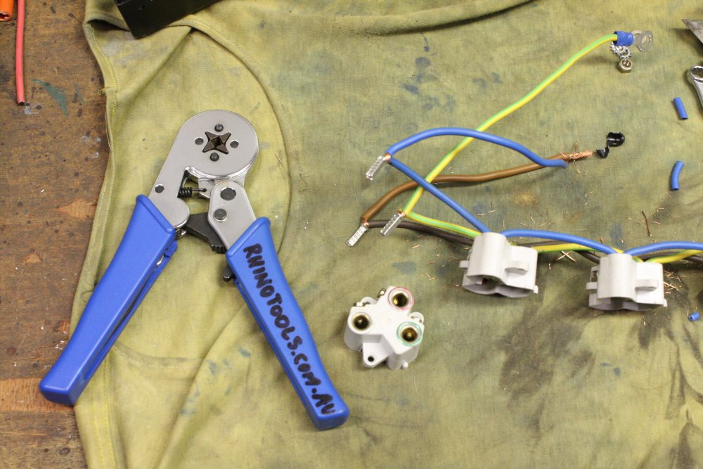
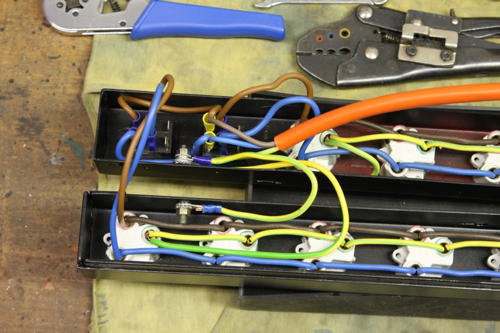
Wiring it up.
1. A 'bootlace crimper' is very useful. Normally the bootlace ferrules have a plastic sleeve at one end, but for this case I pulled them off. No room for them.
2 - 3. Internal wiring.
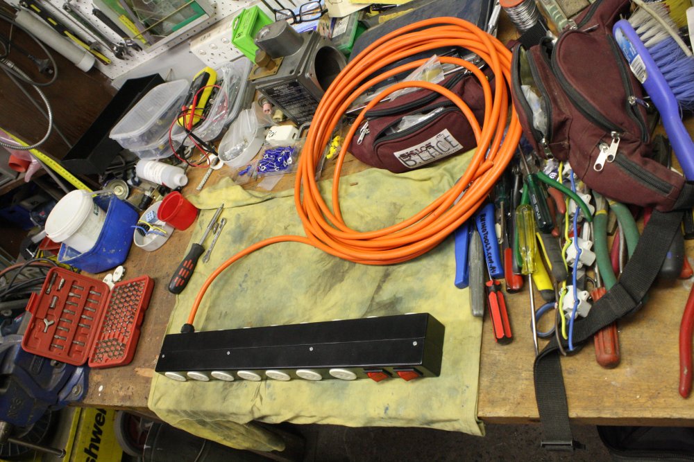
4. Complete. (The cable plug still to do, after I decide how long the cable should be.)
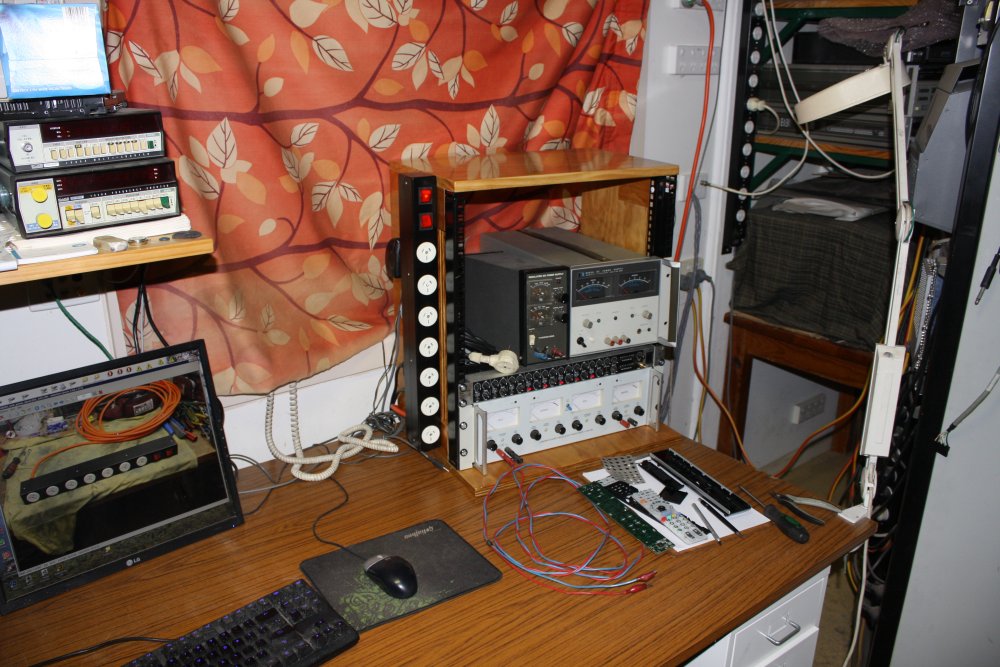
Yay! All plugged in, and now I have a master power switch I can put the stereo amplifier down on the floor out of sight behind the drawers, since there's no need to ever touch it. The 1U mixer unit in the rack takes input from my media server (elsewhere) and is doing it's job here.
So the rack is finished now, right? Right?
Ha ha, as if.
Just for starters, I wanted deep units like that half-width power supply to clear the window sill behind the rack, so the rack can be pushed right back to the wall. But the top of the mixer unit is about 1cm below the window sill, so that doesn't work. Need to pad it up a bit. But if I put in a small 1cm filler, I lose a whole 'one unit' (1U) space in the rack, since the spacing is modular. I could pad under the base, or even under the table legs, but neither appeals.
Also, I want to have a 1U high reserved blank panel, to use for feedthroughs and signal patching, as well as a few other ideas for future features. Which for best ergonomics, should be about the height of the unit just above the mixer. For those 'other things' it should also have a baseplate on which stuff can be mounted.
Another thing this module needs to provide, is a surface for things above it to rest on. Since with that half-width unit there will be a space left for random things.
Yet another problem is that half-width HP 6002A power supply. It's very heavy, and mounting it only via the one side bracket is inadequate. It needs something to support it on both sides, and stop it from skewing.
 |
 |
 |
 |
 |
 |
 |
 |
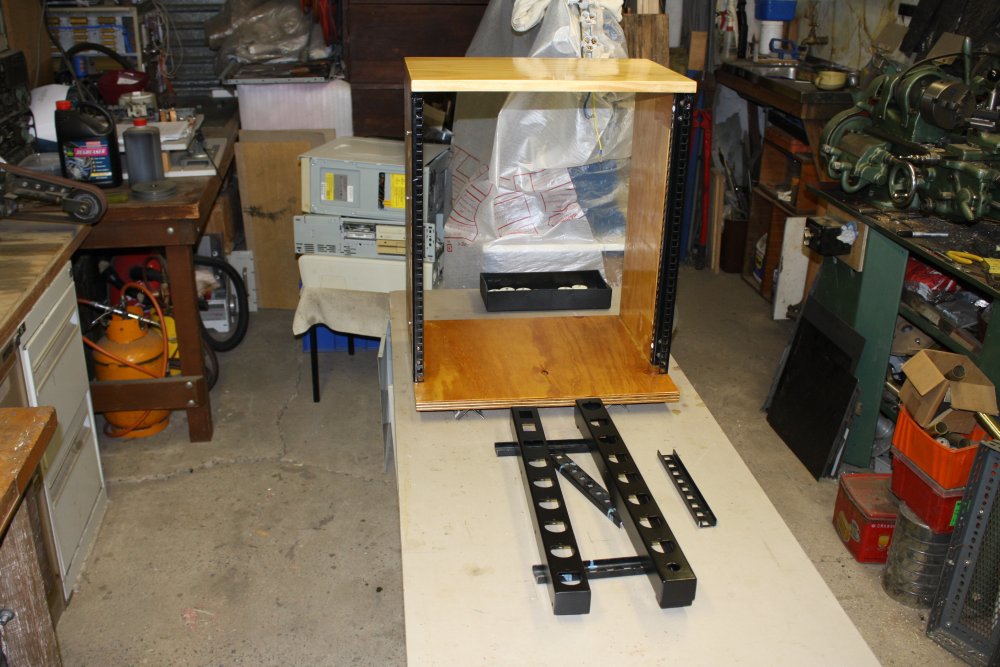
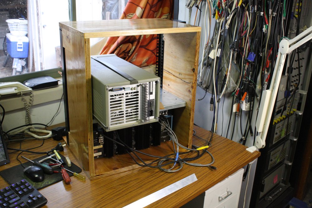
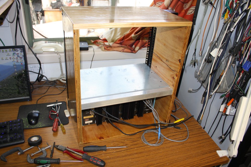
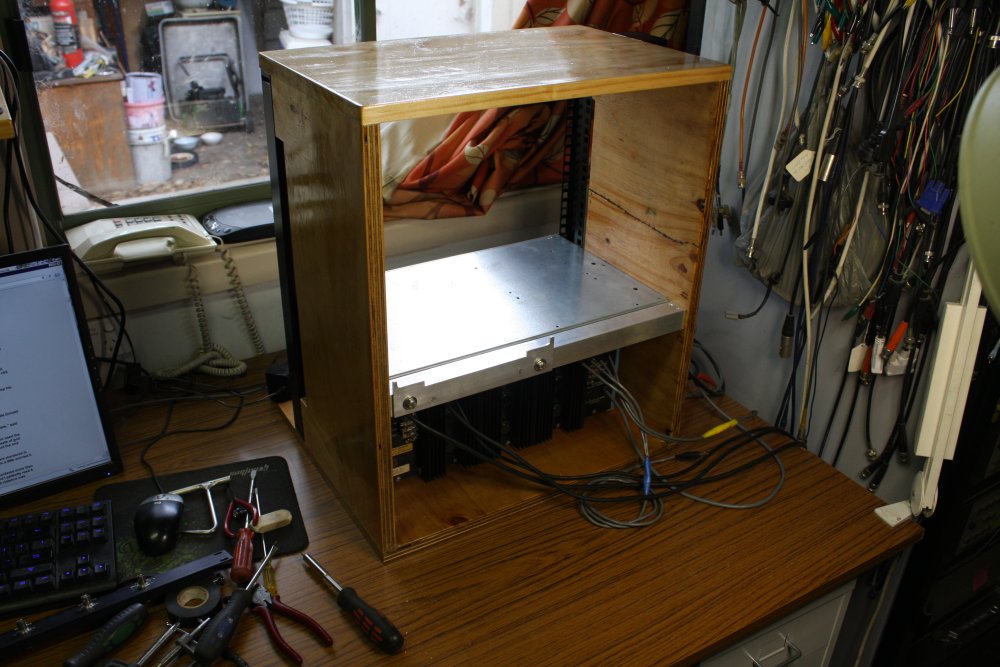
Hence this 1U empty unit, that for now is just a blank front panel and a top plate. It is only held in place by the front panel screws and can be slid out from the front of the rack.
There's also a permanently fixed cross bar at the rear, with an adjustable cradle support for the HP 6002A.
 |
 |
 |
 |
 |
INTERMISSION: A friend is moving overseas, has sold his house, and I helped him clear out his house for the handover. He had a lot of stuff, and gave away most of it. I ended up with literally carloads of tools and cool stuff. Some seen here. That's why there's a gap in these photo dates from the 13th to the 18th — I was busy helping him house clear, then sorting through all the loot at home, getting it cleaned and merged with my gear. So I could move around again — there were a lot of boxes.
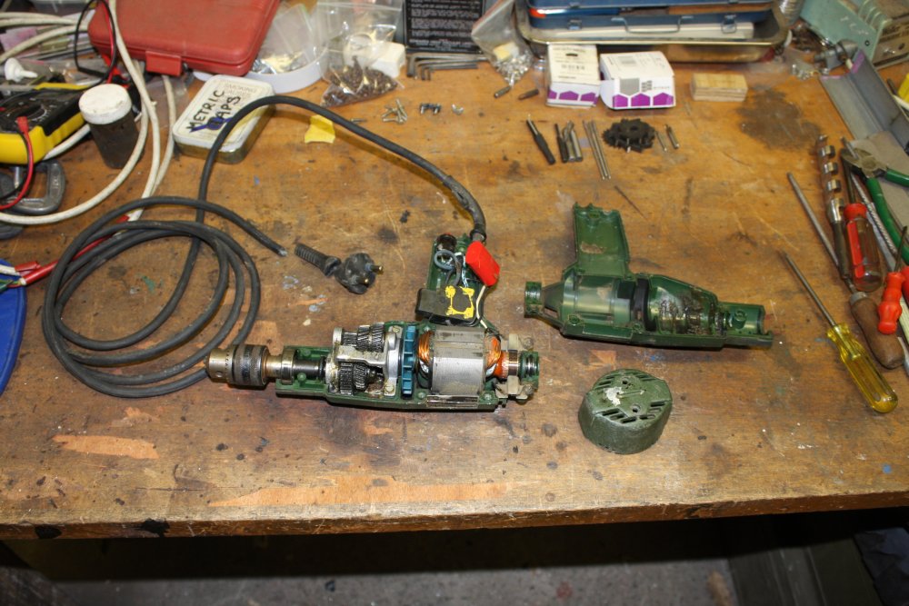
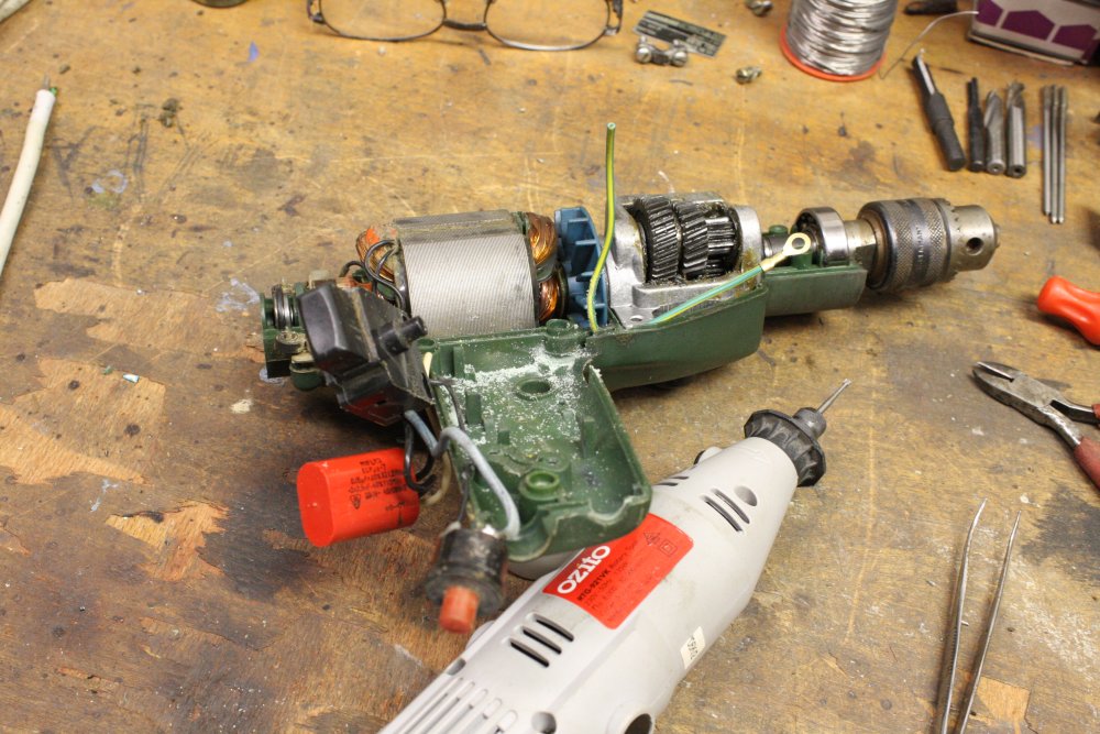
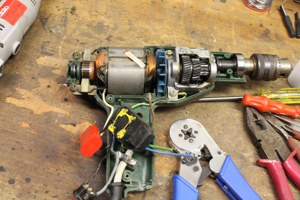
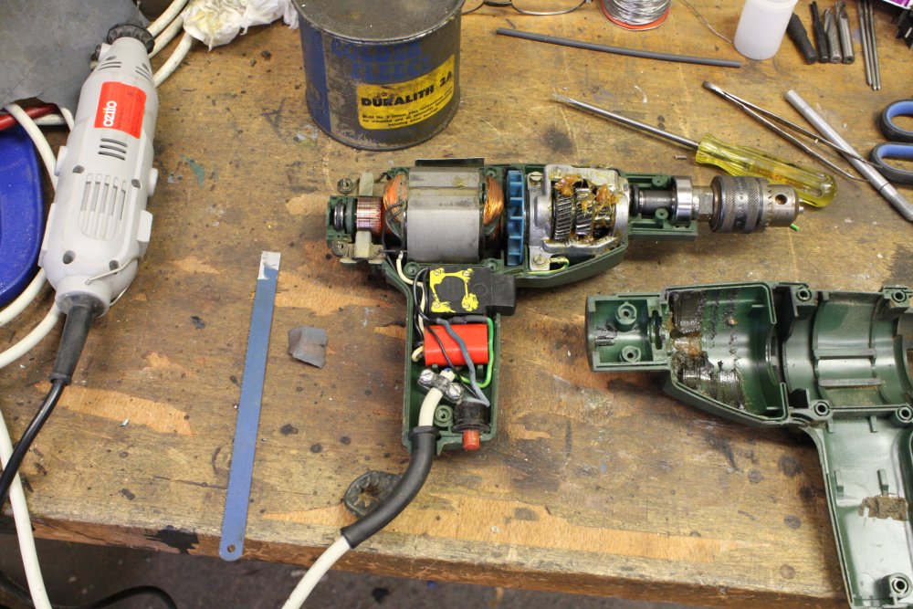
There were still a few boxes of that stuff in the way in my workshop, gradually being dealt with. This old drill belonged to his Polish dad (deceased.) It is rated 230VAC, but has a European 2-pin plug with round pins. And no ground. It works, and seemed a shame to not be able to use it. But on opening it up, I'm a bit leary about the lack of an Earth wire since there's a conduction path from the metal parts of the motor to the chuck. Doesn't seem to be 'double insulated' so far as I can see.
Nothing a new 3-wire mains cord and a bit of hacking with an engraver couldn't fix. I attached the earth wire to the metal frame of the gearbox, and now I'd feel safe using this drill. Apart from being made in Poland, I like it because it came in a wooden box kit, and one of the accessories is a right angle gearbox. Allowing drilling holes in spots with little headroom — a situation for which I previously had no solution.
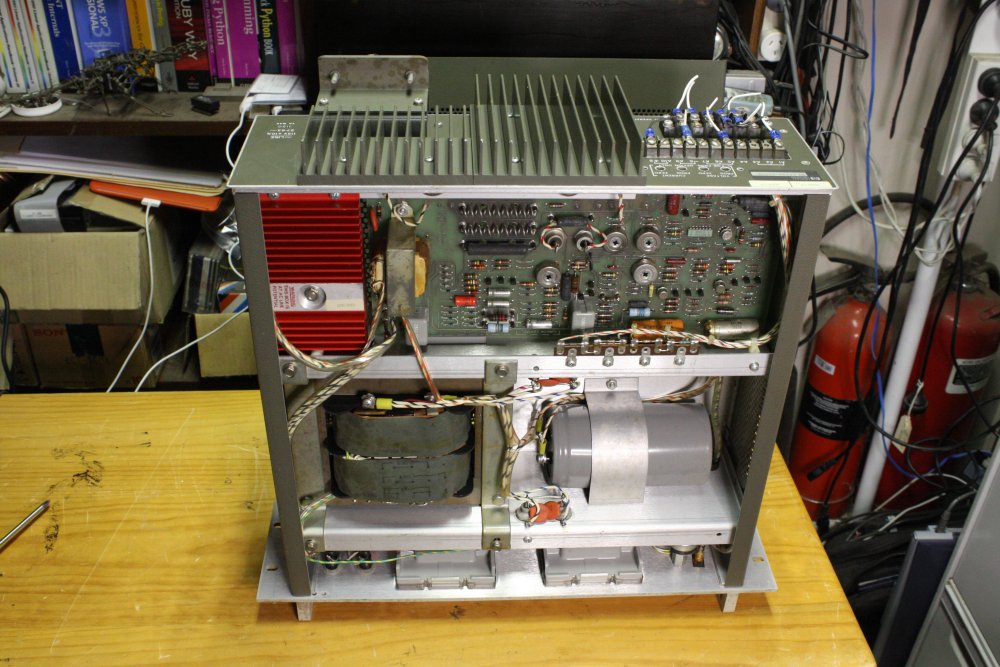
HP 6267B Power Supply Restoration
Back to the rack. What I want to put in the top slot, is an old HP 6267B power supply. I've had a couple in non-working condition for over 10 years. They are from the USA, so are configured for 120V, 60Hz. They were also wired as slave units, remotely controled, so have no front panel adjustments. I'd bought the required wirewound pots a few years ago, but hadn't got around to installing them. Time to fix at least one. I have an original service manual and have worked on similar models in the HP 62xx series before, so it should be easy.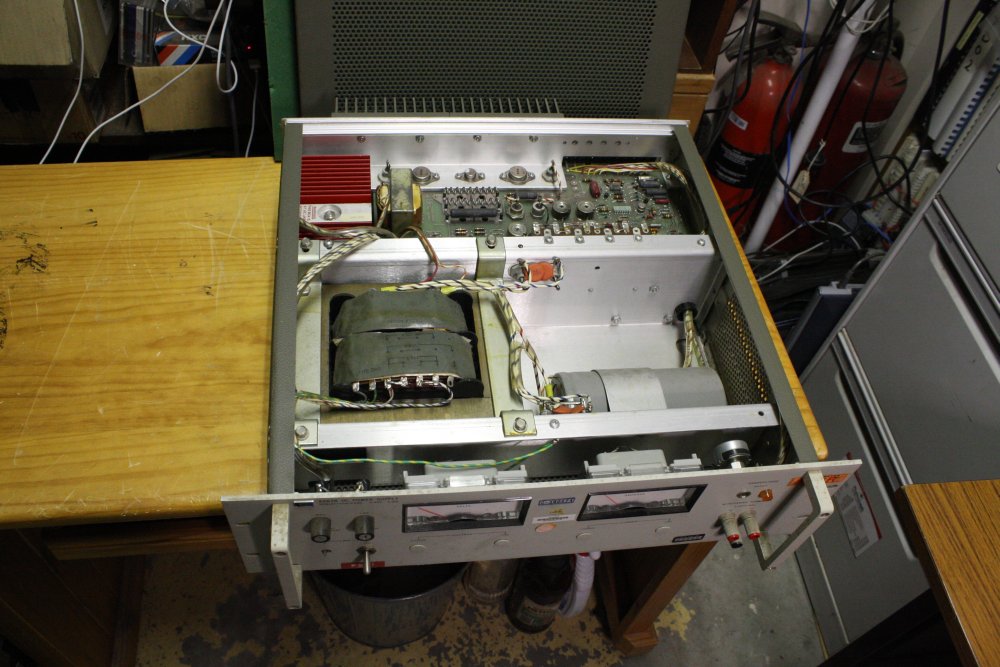 |
 |
 |
 |
 |
1 - 2. Before starting on it. (This is the other unit actually, but they looked about the same.)
3 - 4. It is very heavy, so support rails are a must. I had to buy a length of this steel section ($40 for 6 meters), so together with the Argoshield gas cylinder swap the 'zero cost' aim for this project has been undermined. Still, the gas will last me years, and the steel is mostly for other things.
5. Starting on the supply teardown and repair. It's very dirty, and there are many issues to fix.
The online manual here is usable but has all the usual faults: fax mode, stupid page sequence, skipped pages, skew, schematic foldouts in fragments and missing slices, schematics missing shading blocks, and moire on PCB overlay half-tone areas. I'm so glad I have an original paper copy.
 |
 |
 |
 |
 |
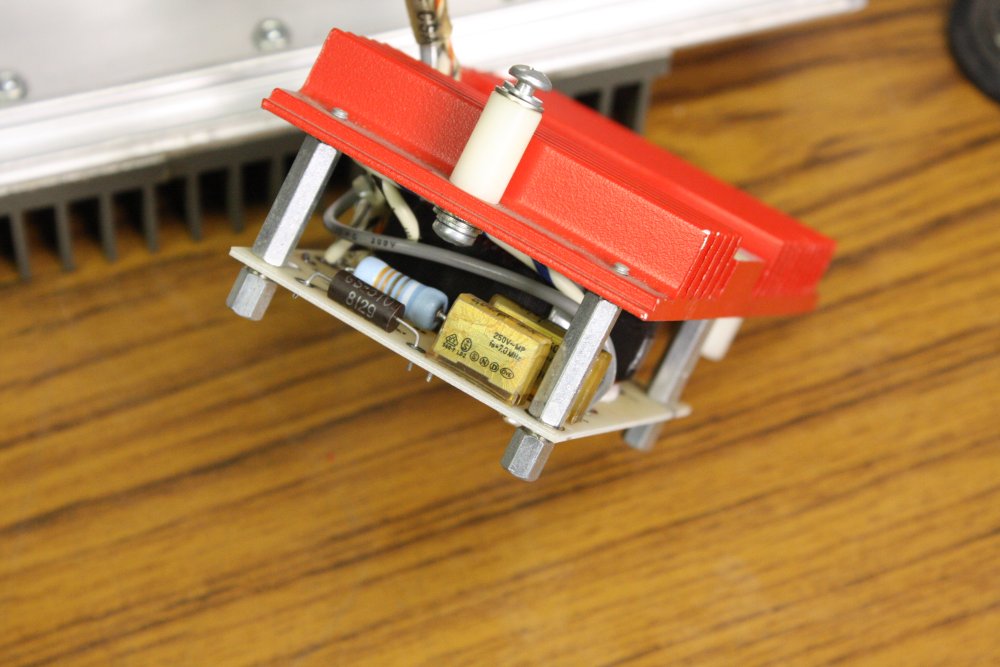
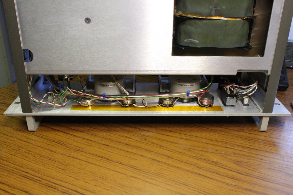
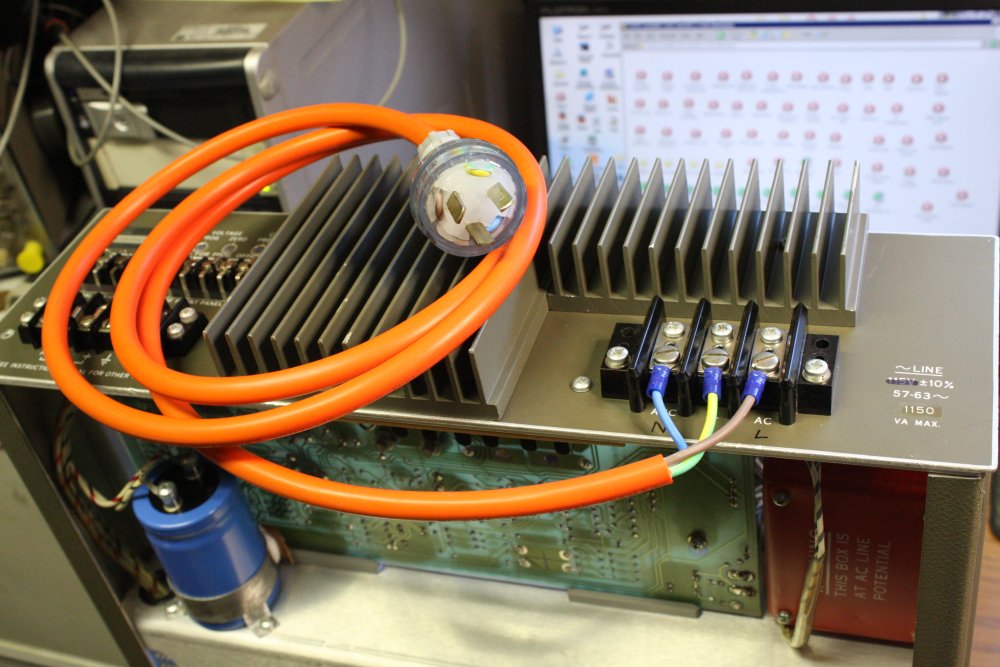
First things first. 'Casting Out the Evil from its Heart' — metaphorically speaking. This red unit is the mains input power Triac phase-controlled pre-regulator, prior to the main transformer. And it contains two of the infamous 'death-stink' polyester capacitors.
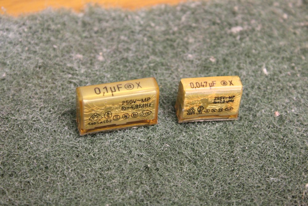
1 - 2. There they are, those two yellowish rectangular things. They are 'mains rated' caps, supposed to withstand 240VAC. Except when they are old, they don't. Because this supply has not been powered up for decades, they are intact. As opposed to festering lumps of foul smelling melted and burned polyester they soon would be if I powered this unit with them still in place. When assembled this circuitry is inside a closed metal box, and the entire thing is painted warning-red because all the metal is at live mains potential when running. As a result of the small, closed metal box, when these caps fail (as they have in similar power supplies and other kinds of equipment I have), the stinky burned plastic smoke they emit condenses on everything else inside. It takes a lot of work to clean off. Also enough of the smoke escapes to make the entire room stink badly for many days afterwards.
The problem with them seems to be that the poured molding epoxy shrinks with age, and cracks. (See pic 2.) Which lets moisture in, and the tightly wound metalized film becomes prone to insulation breakdown. But when it fails, the arc eats away at the super-thin metalization and typically doesn't draw enough current to blow a fuse immediately. Instead it keeps chewing at the plastic, vaporizing a significant proportion of the entire cap. The chemical breakdown products are not pleasant.
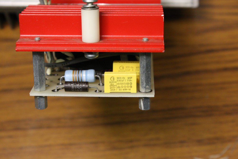
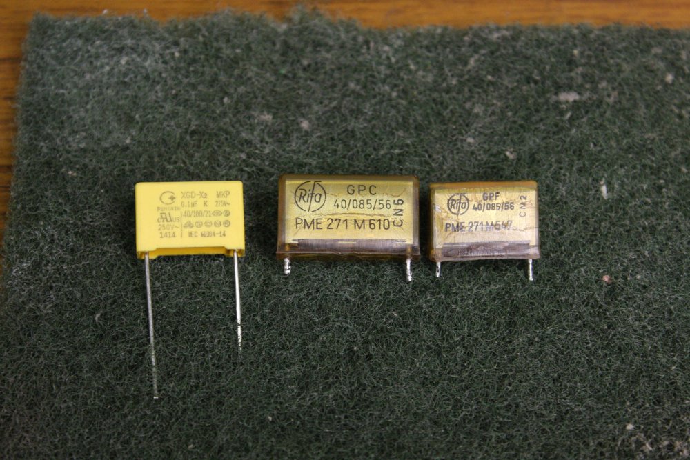
3. Replaced with modern equivalents.
4. I hope... What are the numbers "40/100/21" on the new one, and "40/085/56" on the old ones?
5. The supply temporarily slid into the rack, to get it off the bench. Also a convenient position to work on fitting the new front panel pots. Naturally, three of them had threaded shafts slightly too large to fit the panel holes. The pots were quite difficult to obtain, as they have to be wirewound types and are all different values. The reason they have to be wirewound, is that the circuit puts a significant DC current through them, and carbon film pots tend to develop 'open' spots on the track when subjected to continual DC current from the track to wiper. Open spots would cause the supply output voltage to jump suddenly, and with the unit able to supply up to 40V at 10A (400W), sudden wild jumps in the output are undesirable. Wire wound pots don't do that.
 |
 |
 |
 |
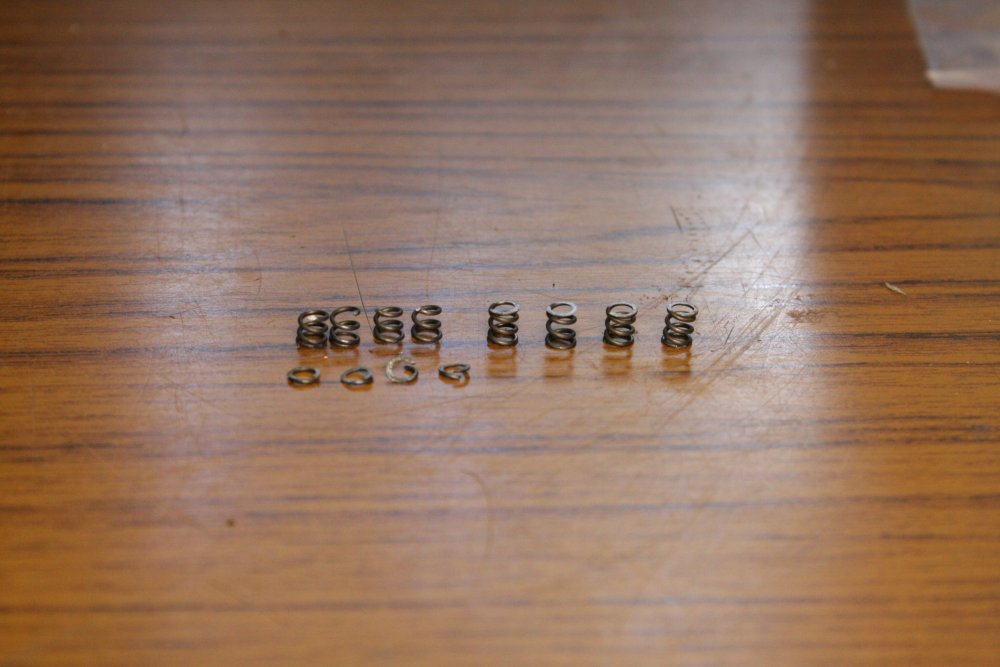 |
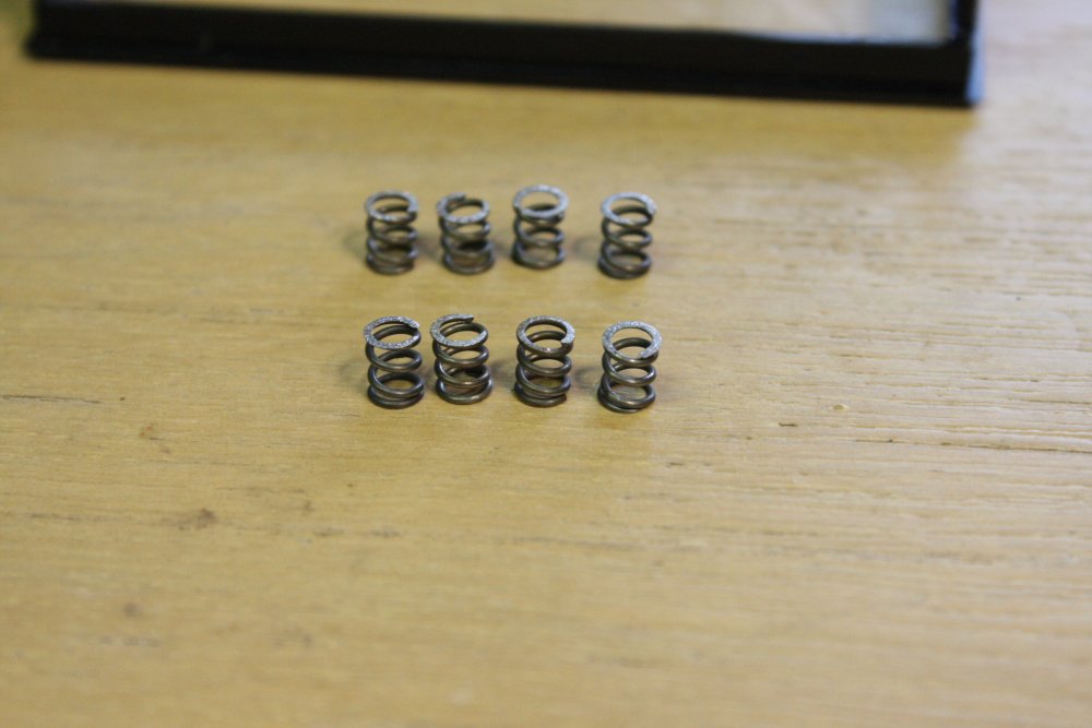
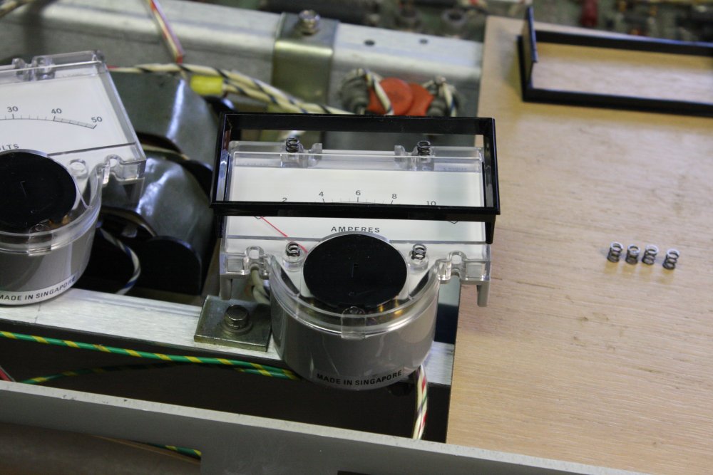
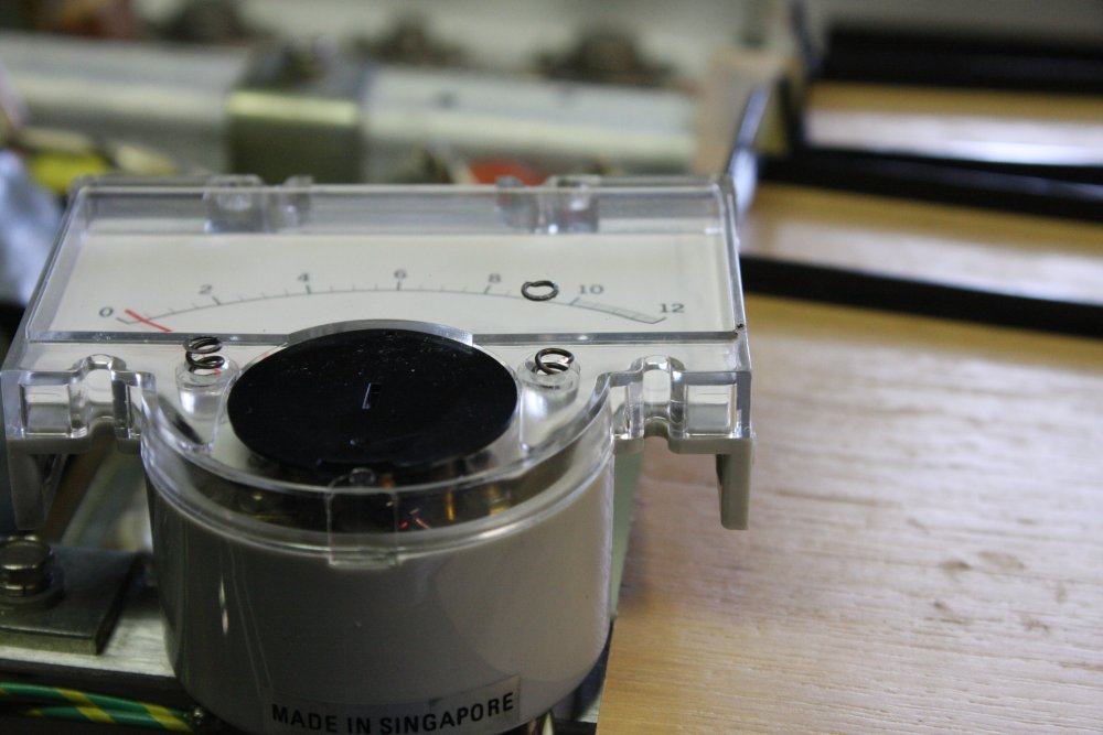
Another problem HP power supplies of this vintage suffer, is cracking of the meter or retaining clip plastic due to the mounting scheme putting the plastic under more strain than it can take in the long term. HP used four small steel springs to push the meter body back away from the aluminium panel, against the plastic bezel clips. But the springs are too strong, and can break the plastic clips eventually.
To reduce the stress on the plastic, disassemble, clip a little off the spring length, and reassemble.
 |
 |
 |
 |
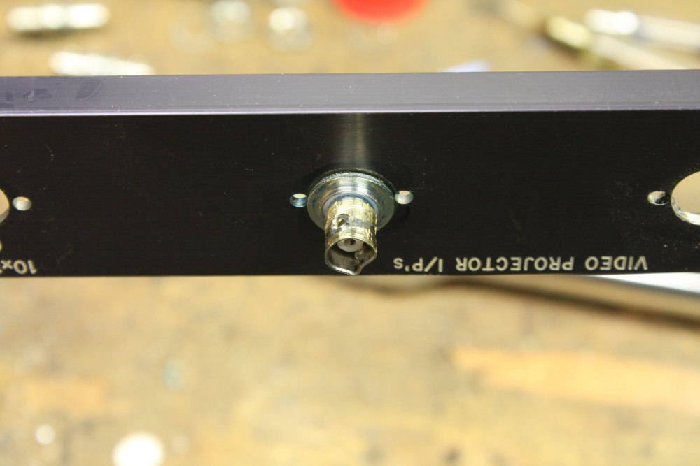 |
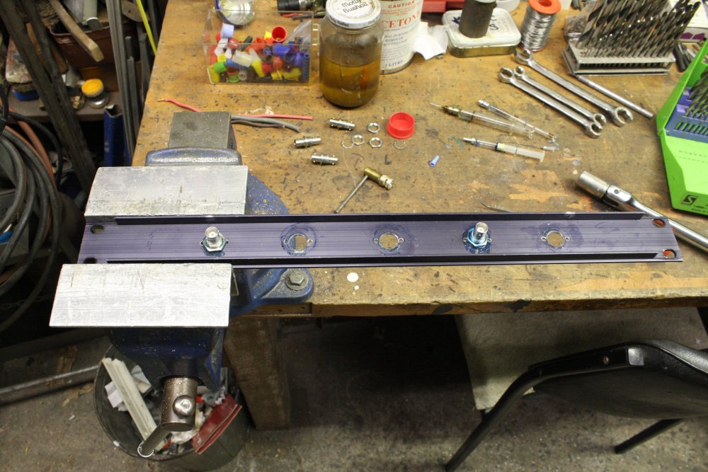
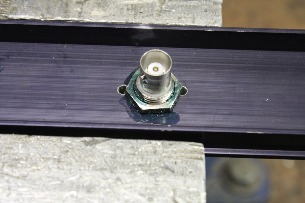
A brief aside. I'd been thinking about that blank panel. One thing needed there is a set of BNC feedthrough connectors, to serve as a small video patch panel. I'm out of those feedthroughs, so was hunting some more in my junkpiles. This 1U panel has five of them, and isn't usable as is since the text on it is engraved into the facia and is too specific to be useful. Good, that's most of the feedthroughs I'll need. Only... it turns out someone used a thread-locking compound on these, that really works. Usually threadlocker will crack off with a bit of force. Not this stuff. I think it's actually that blue-dyed PVC pipe glue. It's been painted on the threads before the nuts were put on and tightened. On the first one I tried to undo, the plug distorted with no sign of the glue giving way. Having already damaged the BNC plug, I then tried real force, gripping the BNC with big pliers and a socket wrench on the nut. It still refused to budge (and the BNC was now utterly destroyed.)
Hmmm.... four left. How to get them off without ruining them?
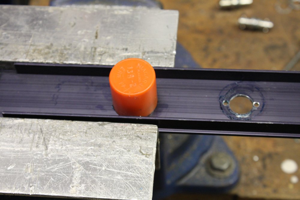
The solution was to wrap the nut and threadlock/glue in a strip of tissue, soak it in acetone, then cover with a small plastic cap and just leave it for half an hour till the acetone softened all the glue in the threads. One by one they all came off easily.
 |
 |
 |
 |
1. These new pots have a quite small spacing between the terminal lugs and the panel. For better insulation I added a couple of layers of capton tape.
2. The grounding also wasn't that great, relying on the chassis to provide Earth connectivity between the mains cable entry grounding point, and other points such as the Ground trace on the PCB. I added a direct ground wire.
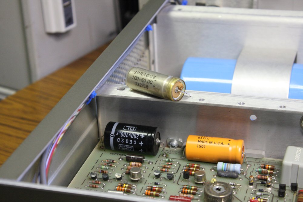
3. A few pins on the back of the PCB were very close to this big capacitor mounting bracket. I glued in an insulating spacer.
4. Added a cable from the front panel pots, to the rear PCB. Only 4 wires required and it wasn't possible to thread them into the existing cable sleeves all the way to the back, so I used a single sheath twin shielded-pair, with grounded shields.
 |
 |
 |
 |
1. C10 in the reference section had leaked. It still measured correct capacitance, but I replaced it anyway. Scrapbox cap, higher voltage rating is irrelevant. I charged it up, checked leakage and cap value before using it.
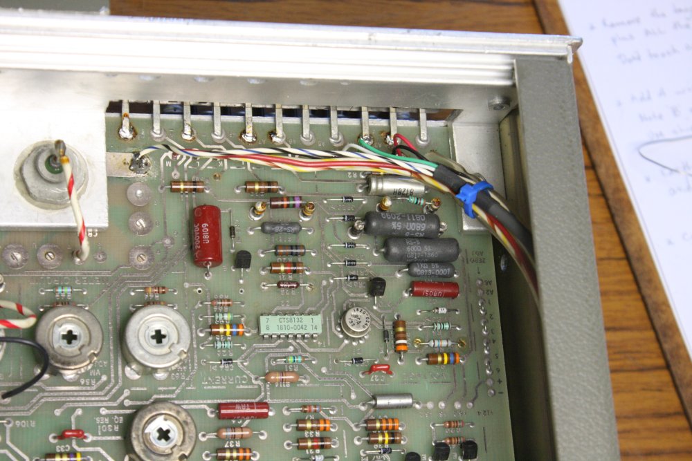
2. The 60Hz to 50Hz mods, per the manual, paragraph 2-25. For the 6267B, three resistors need changing:
R78: 510R --> 270R
R79: 2K4 --> 4K7
3. Wiring from the front panel pots to the rear PCB pads.
4. Shiny new mains cord.
 |
 |
 |
 |
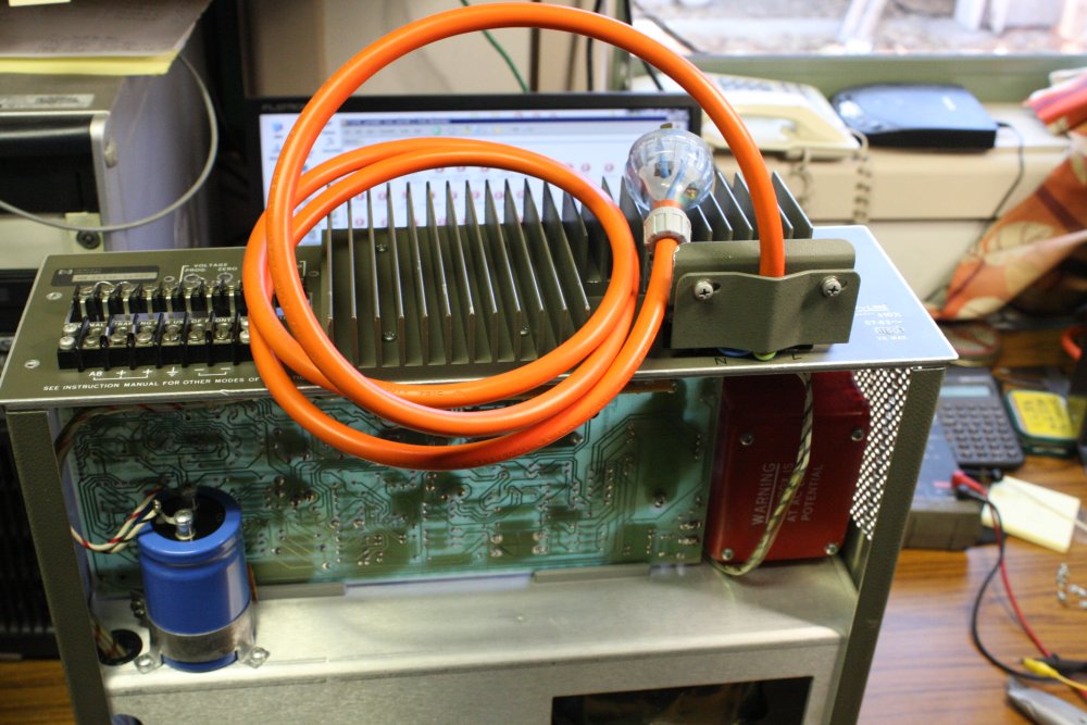
1. Mains terminal block cover and cable clamp in place. Probably wouldn't pass safety regulations today. Like I care.
2. The manual has detailed instructions for changing transformer tap points, etc for 110, 208 and 240V operation. But they forgot to mention the front panel neon, which has a single 33K series resistor off the full mains. I've changed that to two 47K resistors in series. Never mind a sleeve, this is inside the case and there are plenty of other bare mains-live points exposed with the cover off.
So now it was all ready to try powering it up, and running the performance and adjustment proceedures. For which a dummy load is needed. With this supply, at 40V and 10A the load required is 4 ohms, 400W.
No problem, I have a really big, configurable passive dummy load, that I made back in 2010.
What is a problem, is it weighs 52Kg, and is in the other room. Considering whether to move the entire debug process in there, or bring the load here, I sadly concluded it would be best to move the load. I hate moving that thing.
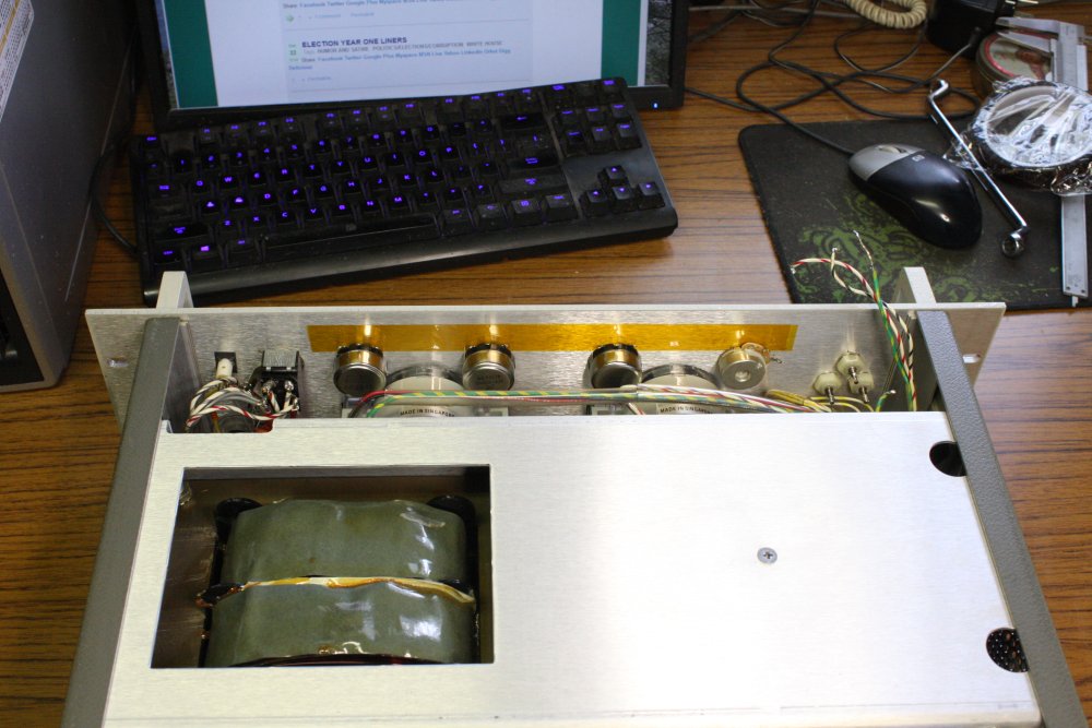
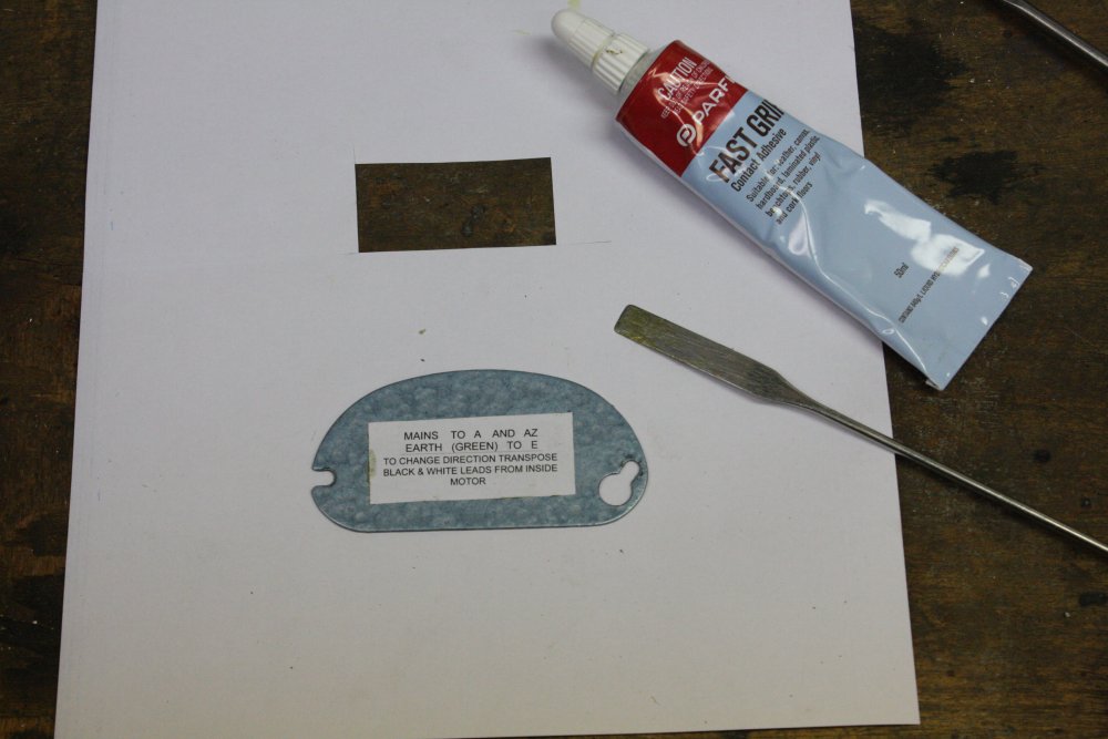
Also it was a little obstructed by other things, which had to be moved too. One of them was the motor for that still not reassembled vacuum pump. Sigh.
3. Which reminded me I still hadn't glued on the new label for the motor cover plate. So, done now. Finally.
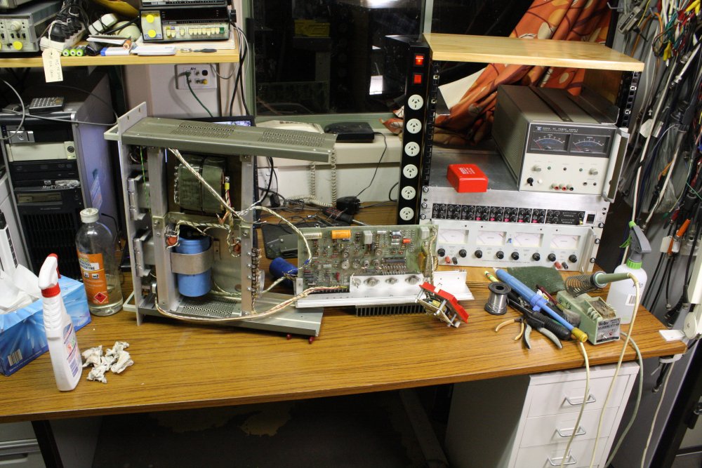
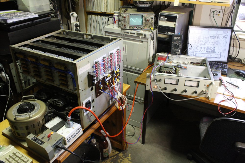
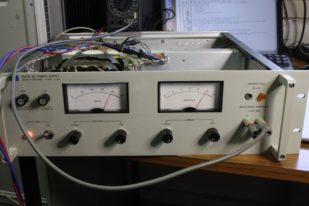
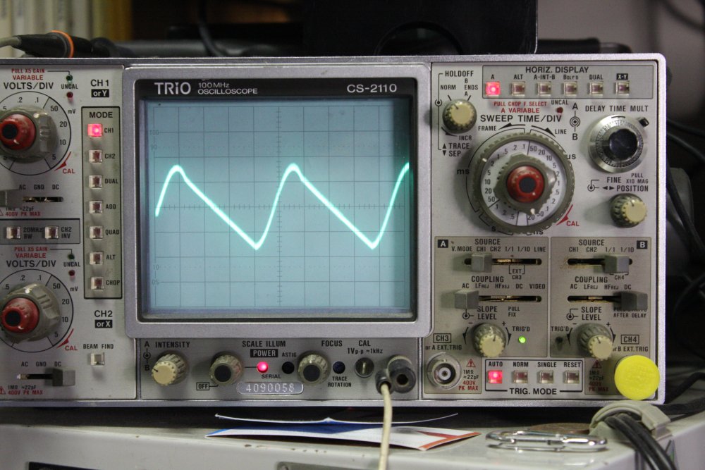
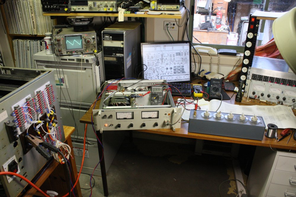
4. The test setup. From the left:
* Big dummy load, only a few resistors of which are being used to make the 4 ohm, 400W load required.
* Scope, showing the ripple on the main DC bus, prior to the linear regulator. This is for adjusting the symmetry of the triac phase control — alternate peaks should be roughly the same level. It didn't need adjustment.
* The 6267B, running at full load. Meter sitting on it showing output voltage.
There were a few little things not quite right; debugging required.
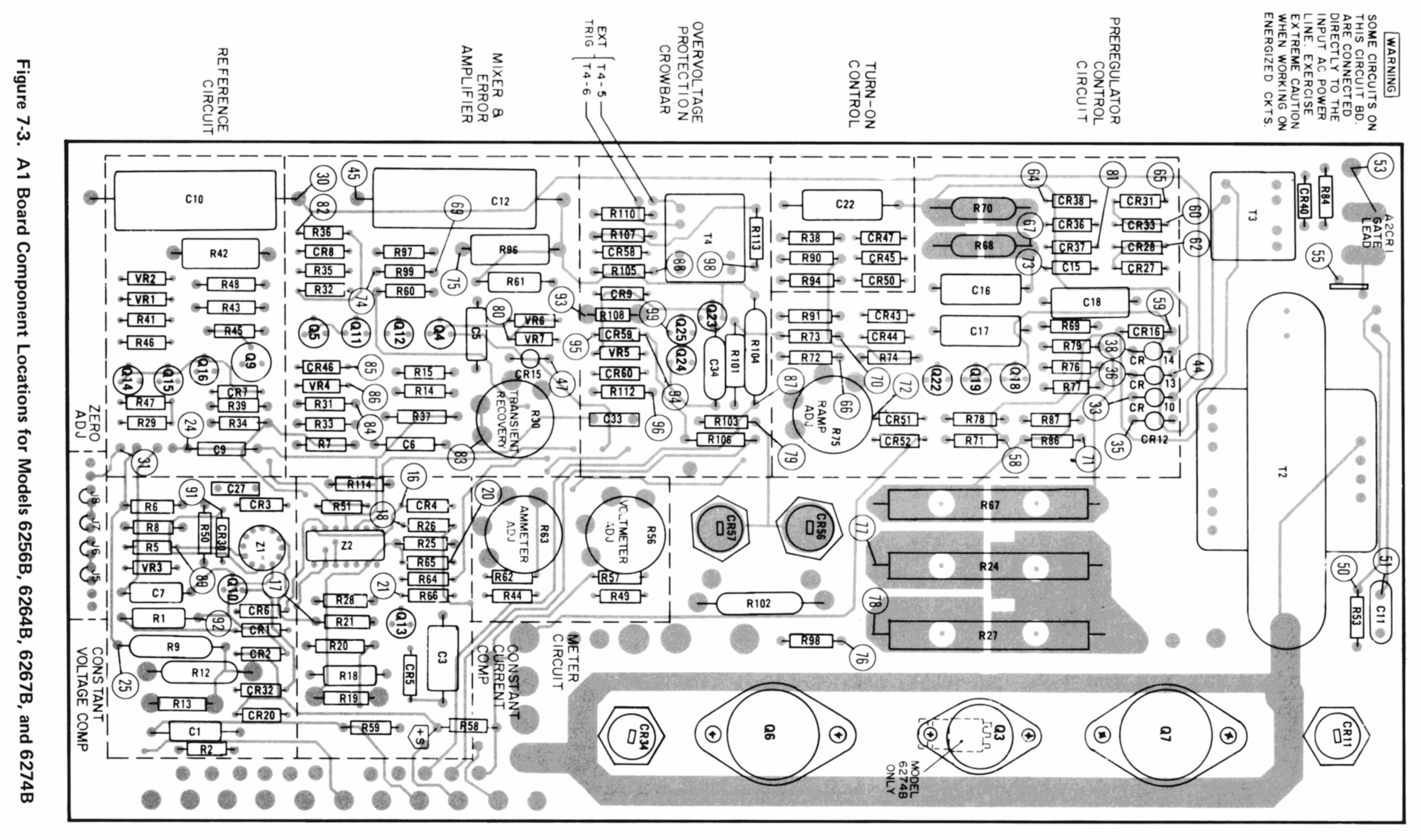 As I mentioned, the online manual for these supplies is pretty bad. I won't be scanning mine for a while yet, but in the meantime here's a better scan of the PCB layout. Click for 2000 px size.
This image could be improved; for one thing the copper trace gray areas are not propperly posterized to a single shade. Thus the file size is bigger than it needs to be. I did it quickly to have something on screen as I worked on the board.
 |
 |
 |
 |
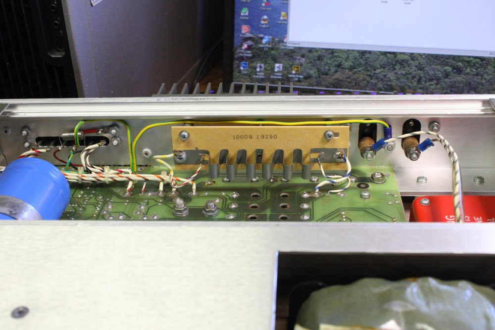
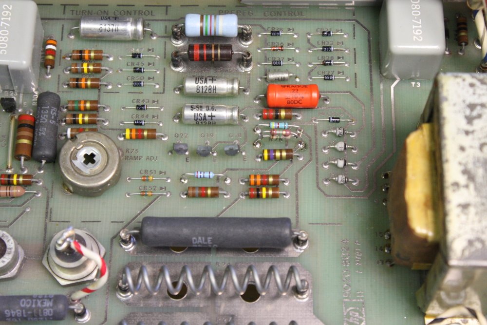
The pre-regulator tracking was a bit off. The aim is to achieve a voltage of 3.7V across the linear regulator stage at full load, regardless of output voltage. There's an adjustment "R75 Ramp adj", but at its limit it still wasn't quite there. I'd noticed this on other 62xx series supplies converted to 240V, so it's a generic problem. The solution is to increase R74 from 4K3 to 10K. Then the adjustment pot achieves the correct pre-reg tracking at near the middle of its turn range.
1 - 2. Closeups.
3. Using a decade box to fiddle with values of R74.
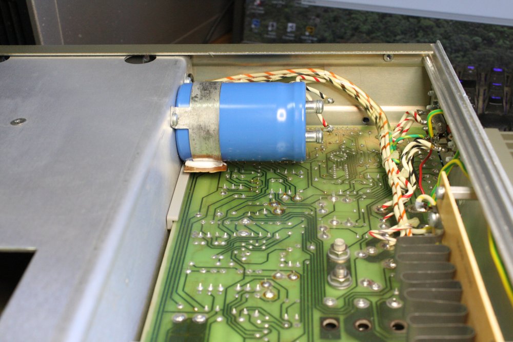
With that fixed, I'd hoped all would be working and I'd be done. But no... the overvoltage crowbar shutdown circuit isn't working. Not that I'd need it, but still, why is it dead?
The circuit is one of those minimal components but subtle things. Made worse by difficulty of probing key points. Some head scratching.
Finally I noticed that the crowbar function has been disabled by substituting a wire link in place of C34. Doh. I guess in the application where this was a slave supply, overvoltage shutdown (which requires turning the supply off and on again to reset) wasn't wanted. After putting in a correct value cap, it works.
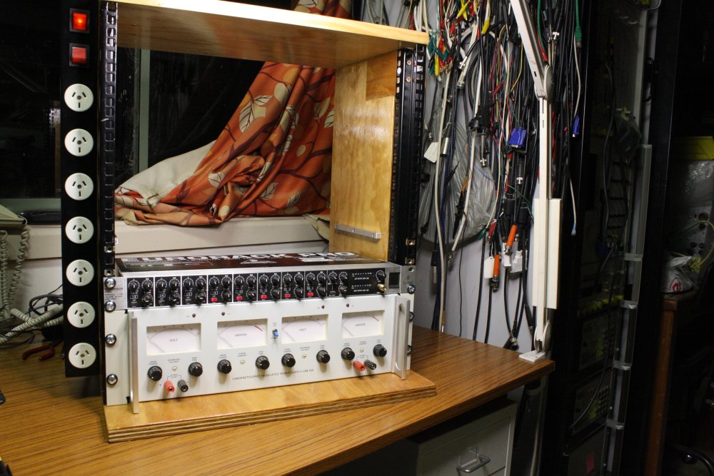
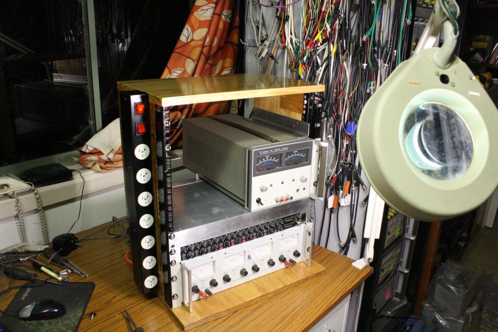
4. With great pleasure, I closed it up, mounted it in my new mini-rack, and tidied all the mess.
Much better!
Not that I get to relax and enjoy it. What with this taking longer than expected, plus the days on that house move and treasure sorting, the list of very urgent chores has backed up badly.
(So of course, I immediately spent a day on a non-urgent chore. Well, it was supposed to be a quick fix.)
20160709 And then...
 |