Two Dummies
(Why mountain climbing and electronics combined, are bad for the feet.)
20100630 TerraHertz http://everist.org
 I'd had an old HP 6269B power supply lying around for a while, but it wasn't in working condition. These are quite massive supplies, able to supply up to 40 Volts at 50 Amps. They have a linear regulator output stage, but despite the high power rating that operates fairly efficiently since there's a pre-regulator consisting of a Triac mains phase controller before the primary transformer. The pre-regulator acts to always maintain a drop of just a few volts across the linear output regulator.
My unit had a few problems, one of which being that it was configured for 60Hz operation. This meant the phase control pre-regulator didn't work correctly on 50Hz mains, as here in Australia.
Another problem was that I didn't have the service manual for it. An online copy of the manual would have turned up eventually, but I'm sick of poor quality scans of manuals, with grainy illustrations, foldout schematics broken into fragments, and so on. Besides, part of my interest in nice old gear like this is shear 'collector's enjoyment' - these are things that were new in the early years of my life, but far beyond my financial reach then. Now I can afford them. And if I'm going to own the instrument, I like to own the original and often very beautiful (to an engineer) manual too.
It took a while to find a manual. And then other time demands got in the way. Finally in mid 2010 I got around to dealing with the 6269B.
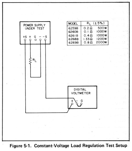
At left, an illustration from the service manual.
Which raises a slight problem. To test a 40V, 50A power supply you need a dummy load of 0.8 Ohms, able to dissipate 2 KW. That "RL" (Resistor, Load) casually mentioned there, is going to be a beast.
Obviously my box of assorted power resistors wasn't going to have anything close to that. Not even if I wired all of those old resistors together. Also, this is not a new problem. I now and then need some kind of really heavy duty dummy load, and always with different values. Time to do something about that.
One thing I had lying around was a big old surplus resistive load in a rackmount frame. It consisted of 18 huge 200 Ohm 250 Watt metal cased resistors, mounted on 6 great big black heatsinks. With a bunch of fans underneath for cooling.
However there's no way to connect up those resistors to make 0.8 Ohms. They are too high a value, and all in parallel still only makes 11.1 Ohms.
But, it's getting close. Looking through my junk boxes I found enough other high power resistors that in conjunction with the rackmount block, would reach the value I needed. Also some more suitable heatsinks. It looked like I'd be able to fit all the extras into that original rackmount unit. Some of the resistors were plain square ceramic body type, but I could see a way to get them heatsink mounted.
Also it would be nice to do this in a way that allowed for easy reconfiguration in future, to get other load values. Another junk boxes search turned up some suitable terminal blocks and some perspex sheet.
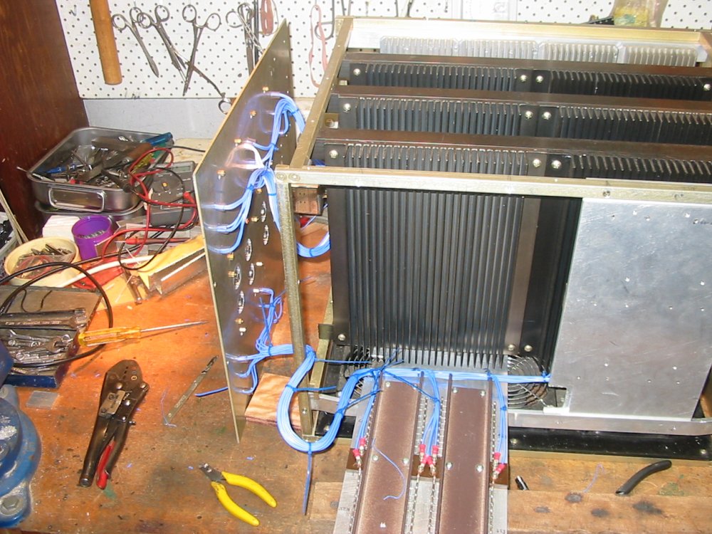
Lastly, there would need to be a fair bit of wiring between the terminal blocks and resistors on the heatsinks. More rummaging turned up the perfect wire. Considering the whole thing could possibly get quite hot, I wanted heat resistant wire. What I found was a big bundle of old military aircraft wiring. It's ideal for this use - good thick multistrand core, with an insulating sleeve of teflon. No chance of that melting and shorting out!
On one side I just mounted some metal-bodied resistors on four heatsinks, then mounted the heatsinks to the frame. Didn't think to take any pics of that at the time, but see pic #4 in the next row.
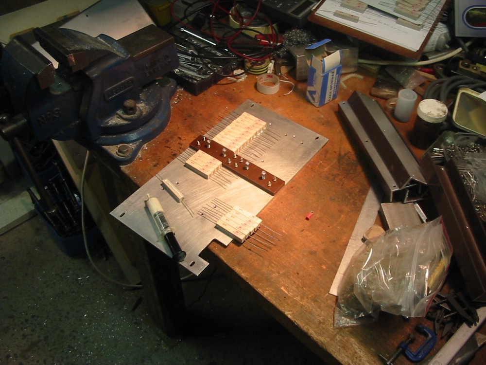
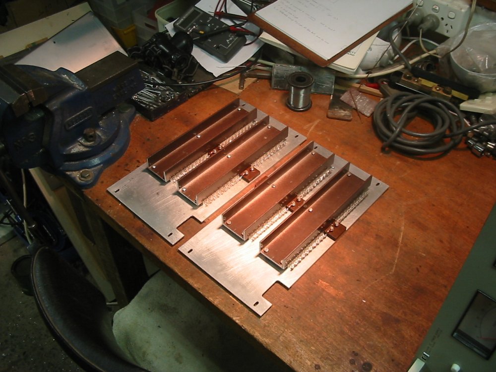
Mounting the ceramic bodied resistors was a bit harder. These were all 10 Ohm, 10 W, and I had a big bag of them. Enough to make eight banks of 10 resistors in parallel, for eight 1 Ohm, 100 Watt resistors.
For these I used a couple of bits of thick scrap aluminium plate as bases, and some rectangular aluminium U section cut to lengths as clamp-downs and more heatsink fin area. Applying heat conductive grease between the resistors and metal.
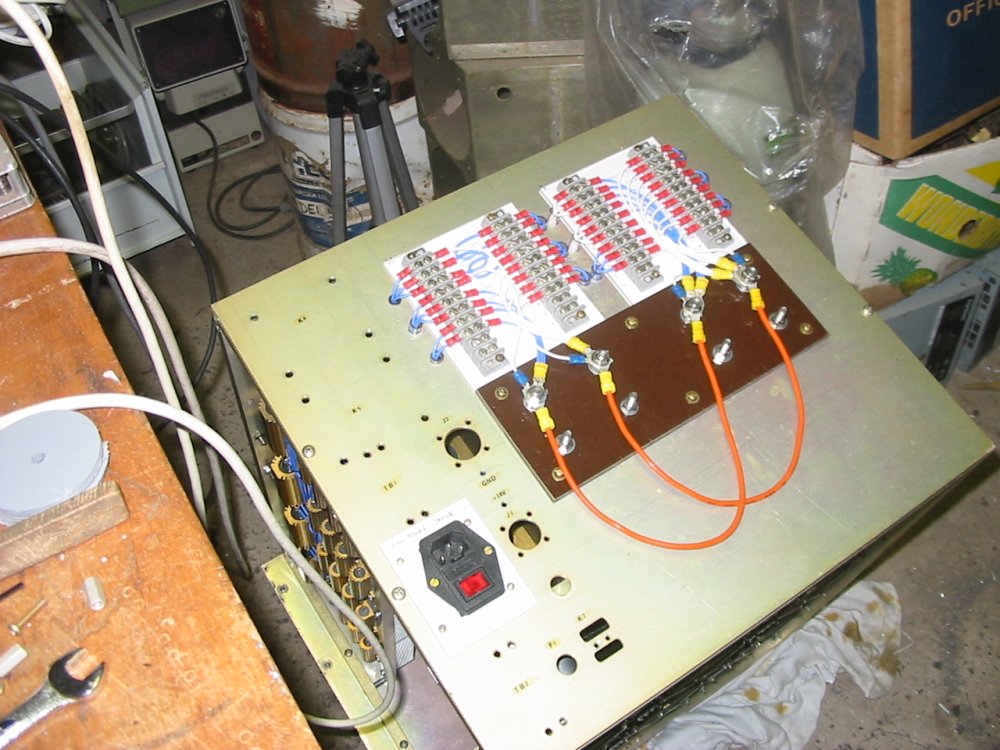
On each metal plate, there's a terminal strip made of two sheets of cloth-bakelite. A thin backing sheet, and a thicker one for the electrical terminal screws. All held in place by the screws that clamp down the aluminium U channels.
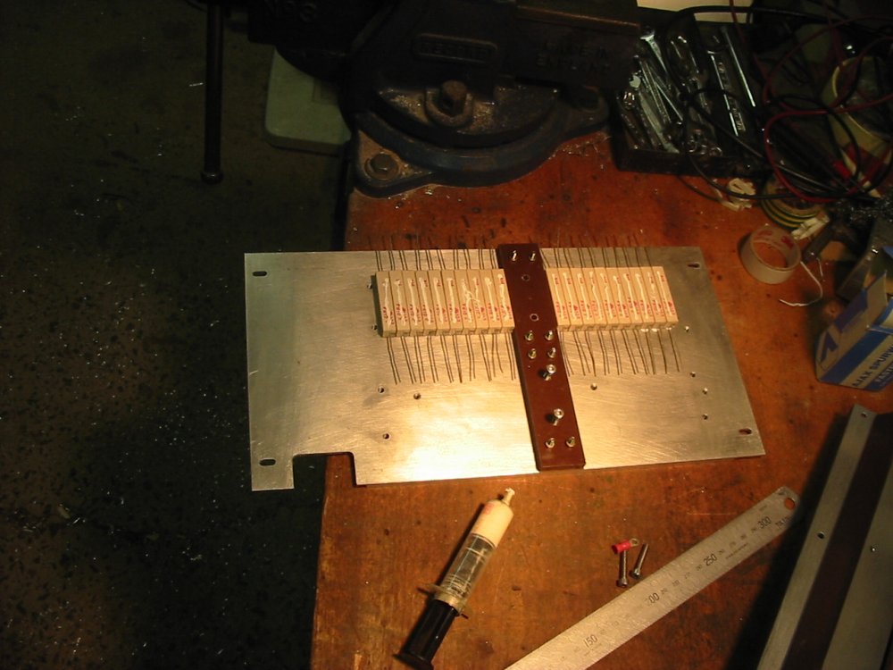
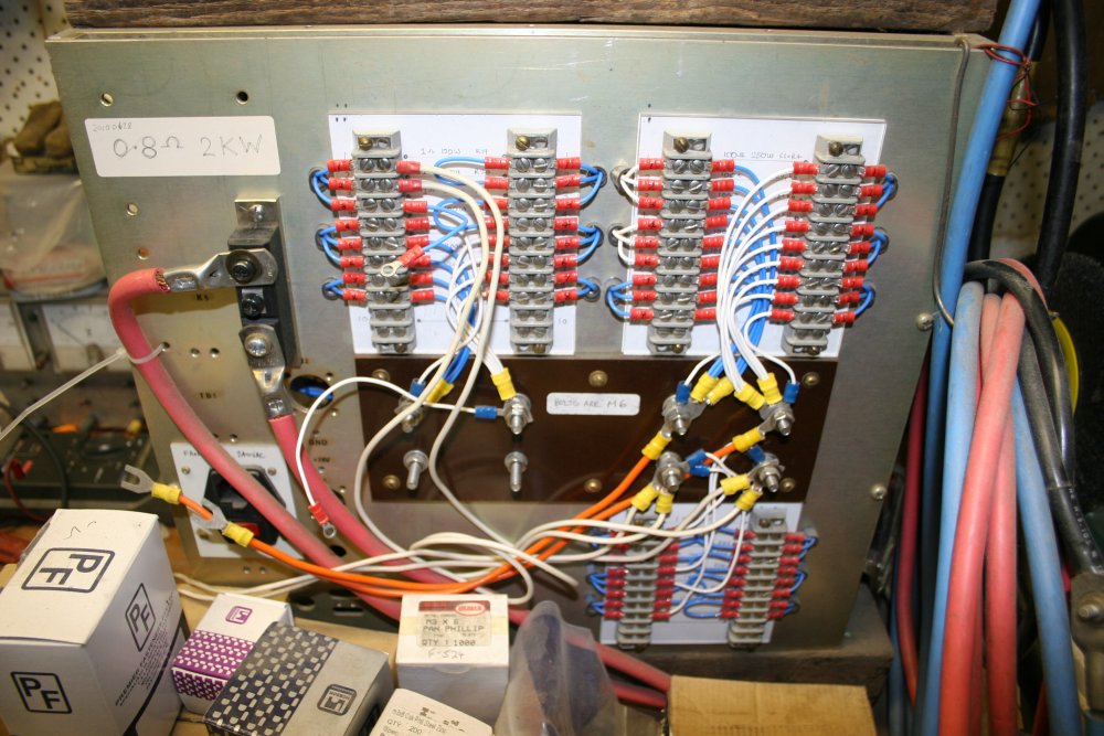
On the rear panel the individual power resistors are terminated with screw lugs to the terminal blocks. Those are mounted on perspex sheets, with paper underneath detailing the resistor values at each point. A central bakelite sheet carries 8 heavy stainless screw connection points, to allow flexible interconnection of the resistors.
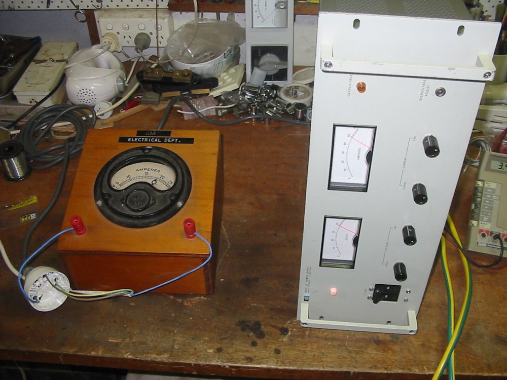
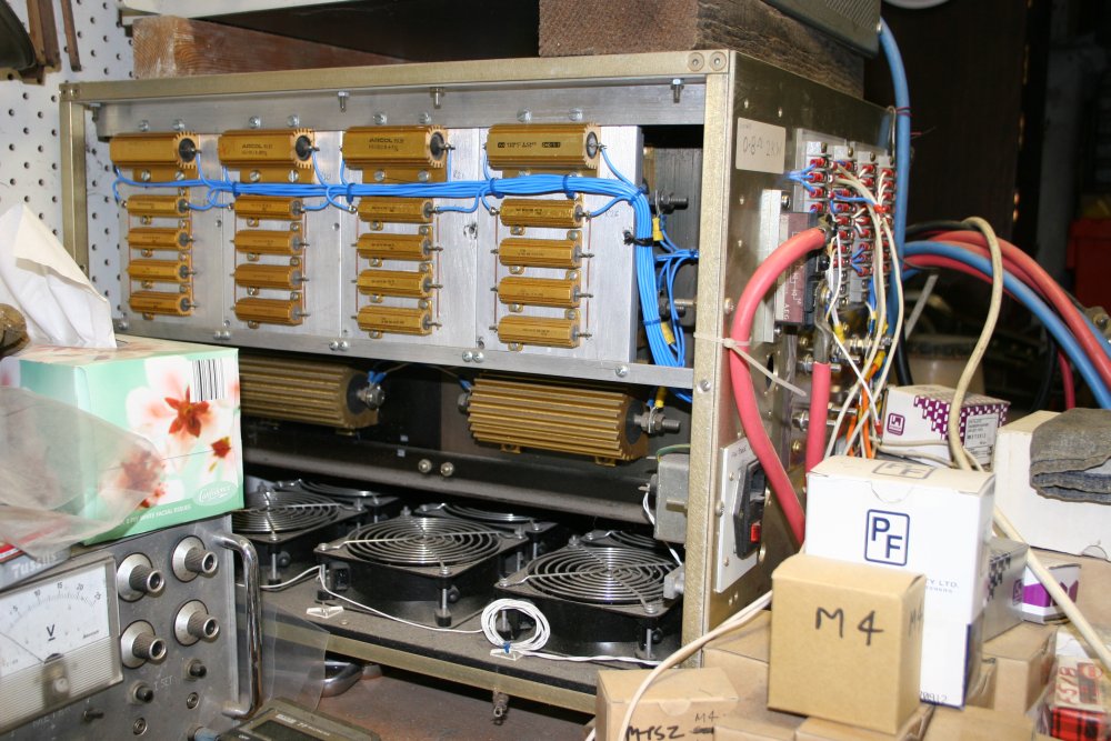
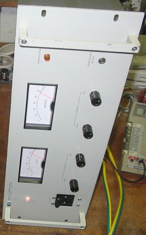
Pics 1 & 2 were during adjustment and tests of the HP 6269B supply. It's shown under full load; 40V at 50 Amps, driving into 0.8 Ohms of the finished dummy load. Mains draw according to that old moving coil meter was 18 Amps at 230V, but I have no idea how accurate that would be, given the phase switched (non-sinusoidal) mains load of this supply. I didn't run this for very long — despite being the middle of winter, and that a large electric bar heater would be in the same consumption order of magnitude, the way this thing hums totally makes it sound like it costs a fortune to operate at full load!
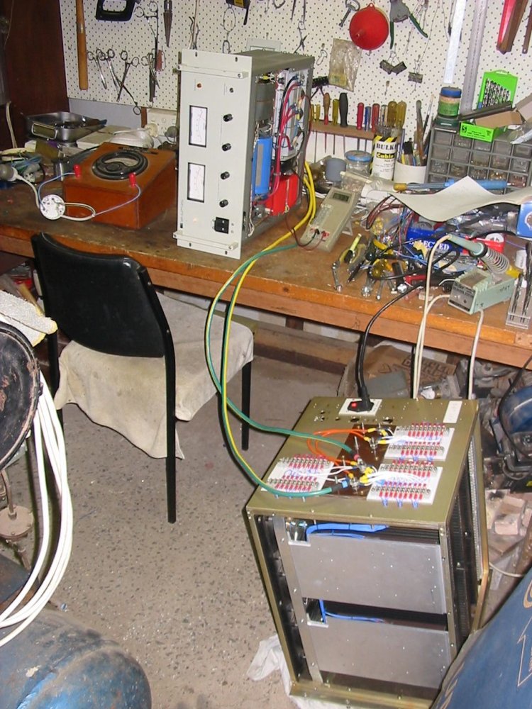
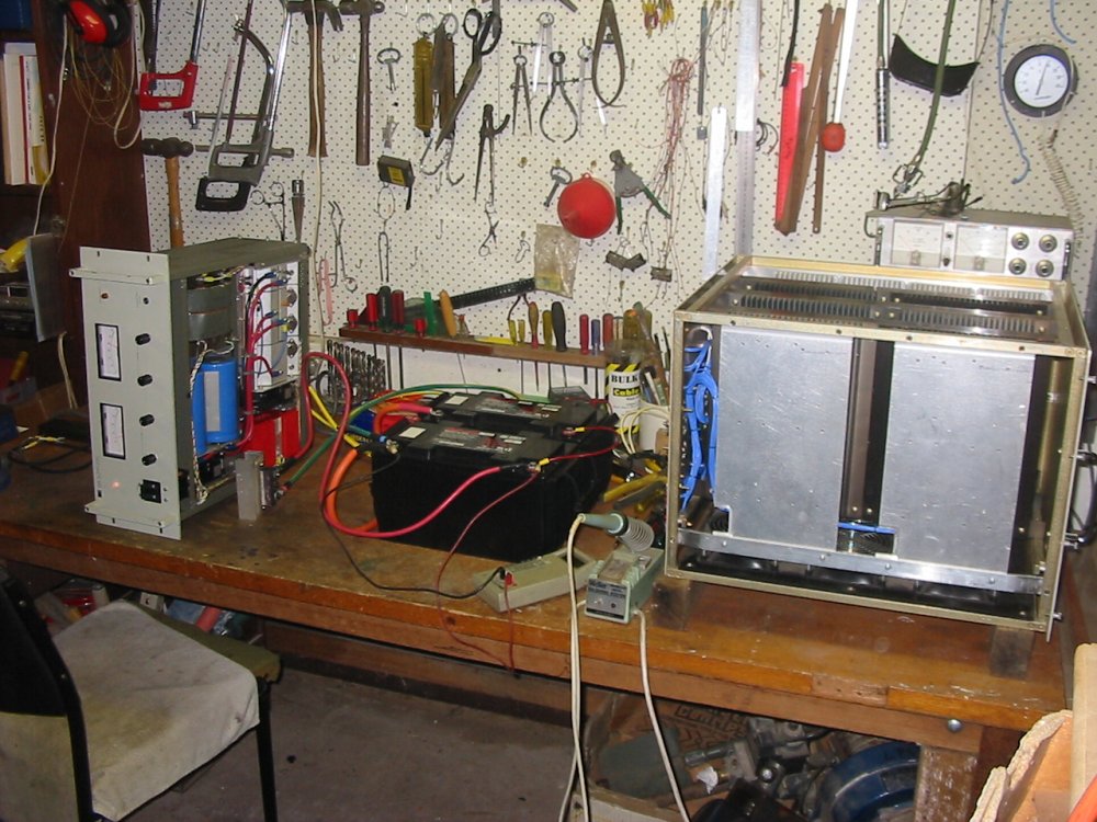
Pic 3 is the HP 6269B doing one of the things it's good for — fast charging large batteries.
The last two pics are of the dummy load in its more or less permanent home on my workbench.
So that's one dummy load.
The other dummy, is me.
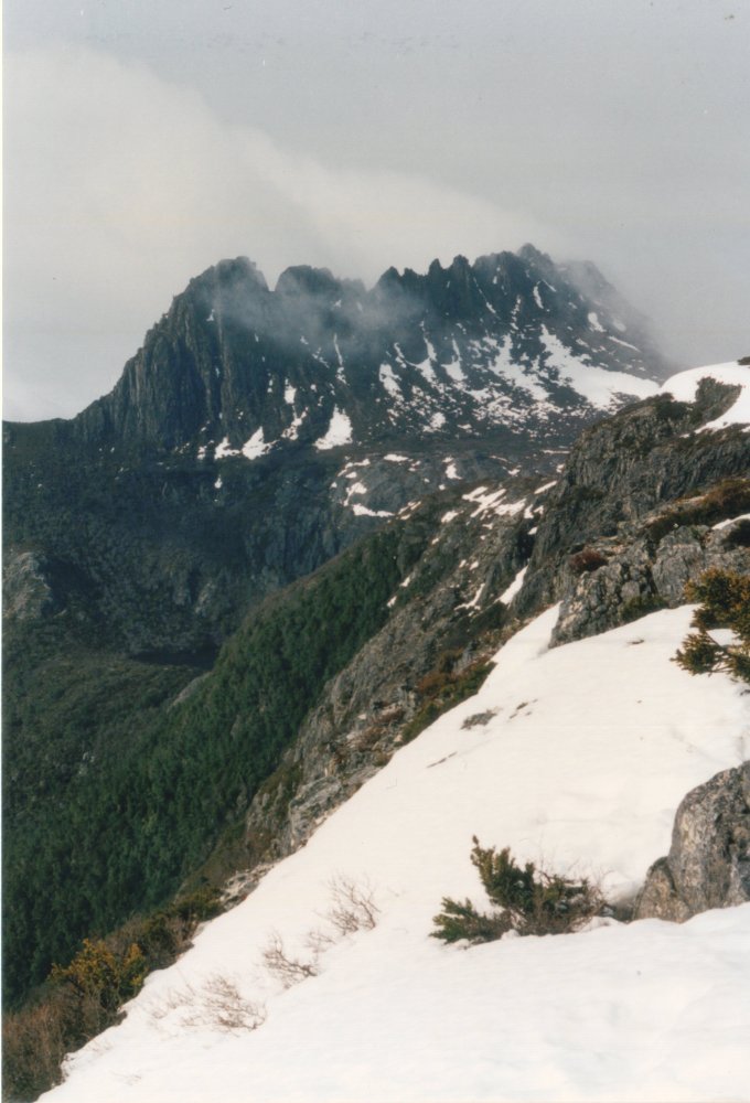
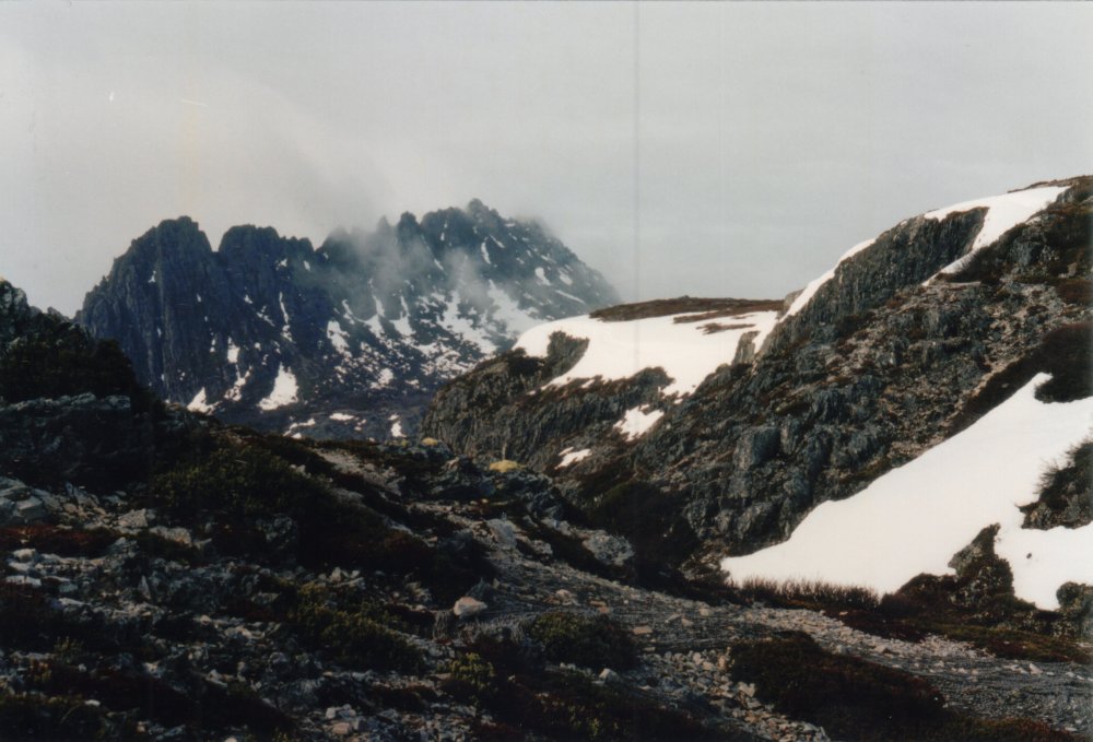
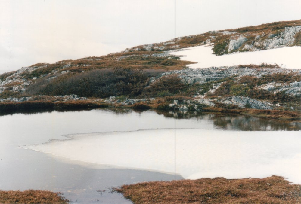
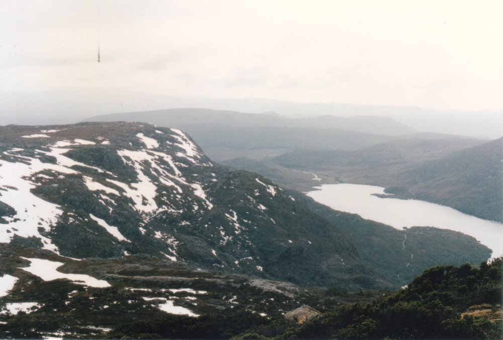
Many years ago, on a family holiday in Tasmania, I did a solitary day walk to the top of Cradle Mountain, in the SW Wilderness area. It was early Spring and the NPWS office in the park said I'd be the first person attempting that climb this season, and it would still have deep snowdrifts.
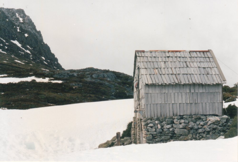
I am a competent, experienced bushwalker and had all the required cold weather gear except snow gaiters. I knew I should have had them, but the holiday itinerary hadn't worked out for finding a snow gear supplier and buying a pair. The morning walk to the base of the mountain had been OK — plenty of snow around on the plateau, but the walking path had been clear. Nearing the summit it was a different story. There was indeed lots of snow, with long sections of untrodden knee-deep soft snow. The route was marked with snowpoles, and was easy to follow. I slogged through the drifts, so of course without snow gaiters my boots filled up with melting snow. By the time I got to the summit my feet were extremely cold.
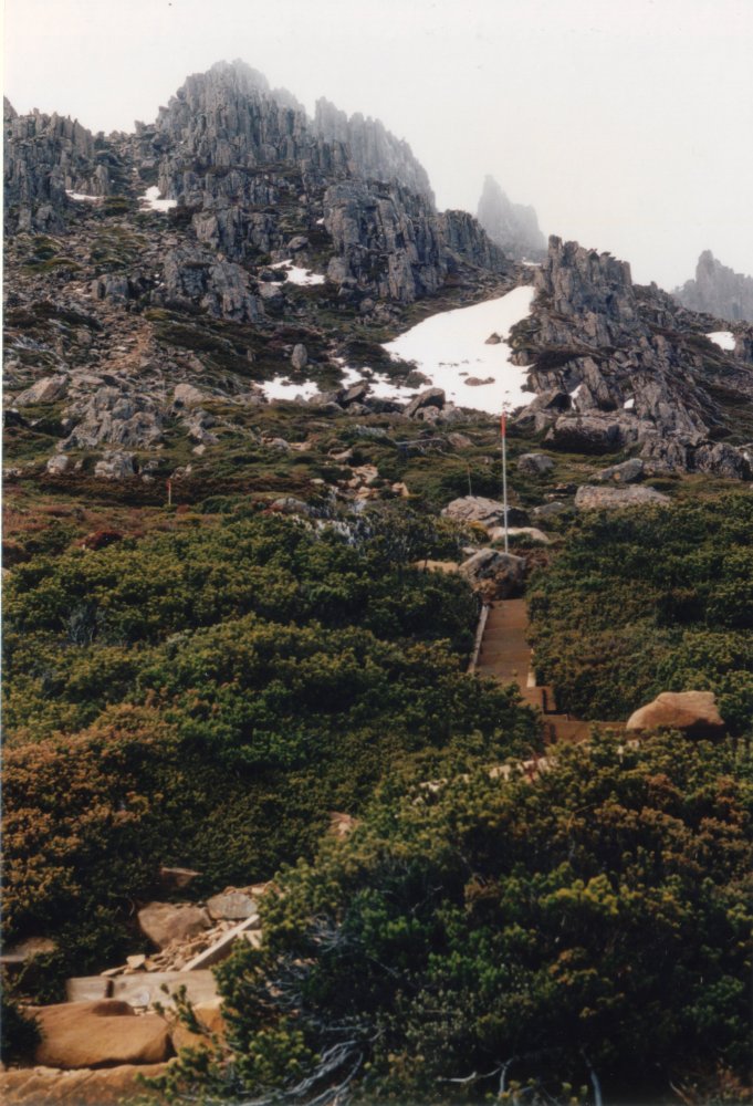
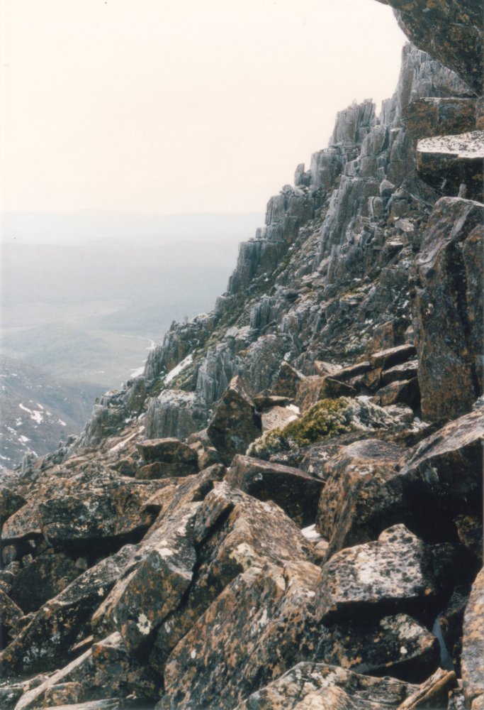
Another party arrived at the top after me, and we all stayed there a while admiring the mist and hoping it would go away for long enough to see the view. I had only a film camera, with only a few shots left on the roll and no spare roll. Same as with the snow gaiters, there'd been no opportunity in the last few days to buy any. So I was preserving film, waiting for any half decent photo-op. I had my boots off, and socks attempting to dry on a rock. It was overcast and cold, so that wasn't working much. The other party left. My feet were still feeling cold but OK at this point.
Then the clouds very rapidly lowered to just above the peak, and it started raining and snowing, with some wind. I began losing sensation in my feet. Put wet socks and boots back on, and started down the mountain as fast as possible. What with the rain and potential frostbite emergency, I ended up with no photos at all from the summit.
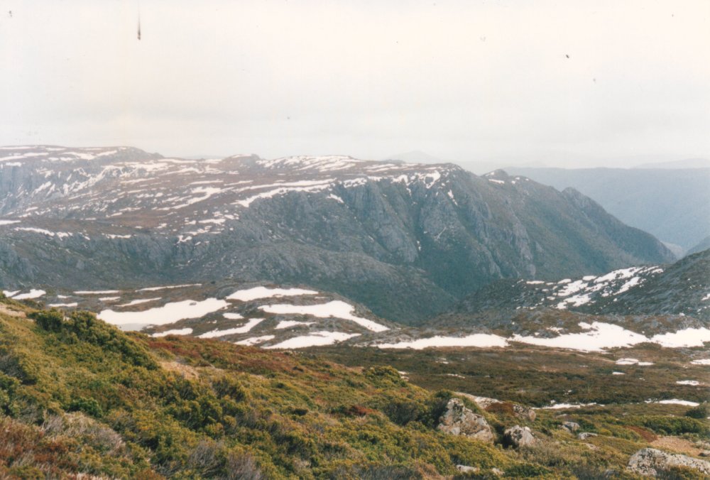
More slogging through snow drifts. Within a short time I couldn't feel anything below about mid-calf. Kept going urgently, walking on completely numb feet. Every now and then I'd stop, remove boots and socks, and massage my calves and feet to try to get warm blood through them. Then kept going. Eventually got below the snow line, into just rain. It was half a day's walk back to the carpark, in cold rain most of the way. Some feeling returned to my feet, and it appeared I didn't have frostbite.
However my toes and forward soles of both feet remained quite numb, and did not recover normal feeling for over a year. A close call.
Then in 2010 when I was constructing that dummy load, I dug out the old salvaged military avionics wire for it. I'd found the wire years ago in a junkyard, had it stored away since. Over three days I handled a lot of that wire, forming and binding it in looms, as you can see in the pics. The wire felt slippery, more so than teflon normally does. I'd noticed the tip of my fingers and thumbs picking up a slippery feeling, as if something like silicone oil was rubbing off the wire and absorbing into my skin. It would not wash off with soap or detergent. Only in the later stages of the dummy load construction I noticed that the affected skin began dying. Very seriously, right down to the subcutaneous layers. It turned into stiff dead callus, and cracked right through till the cracks bled. For about a week I had to keep most of my fingertips wrapped in elastoplast, as the cracks were very sore on contact.
Worse, my entire body started to feel a bit numb. Hard to describe - as if touch was somehow fainter and distant. Noticeable everywhere, particularly my arms and back.
But my feet - the same areas that had been numb from the cold exposure, now became very numb again. A really horrible feeling.
The numbnes of my body gradually faded ( I think, it's hard to tell if it's 100% normal again), but my feet never fully recovered. It's now 2016 and they are still somewhat numb. It makes me a little clumsy walking - I don't get as much positional-pressure feedback from pads of feet and toes as there should be.
At the time I'd guessed the wire was slippery with a teflon breakdown product, looked up on web, called C8. My doctor could find no tests for C8 contamination available in Australia, though there are in USA. Much later I was informed by someone familiar with military aircraft wiring, that such wire has molybdenum blended in with the teflon to improve abrasion resistance, and that molybdenum poisoning is a known hazard of handling it. However web searches find nothing to corroborate this.
There's a couple of online discussions of this on the eevblog.com electronics forum starting here and here.
So, it was a simple, quick project, and worked as intended. But in building it I seem to have caused some serious (permanent?) peripheral nerve damage. If anyone has any suggestions, I'd like to hear them. I still have samples of the wire, if I could find some way to have it checked to see if it really does contain a molybdenum compound. And if that's actually harmful. Or another suggestion: hydrofluoric acid as a breakdown product impurity.