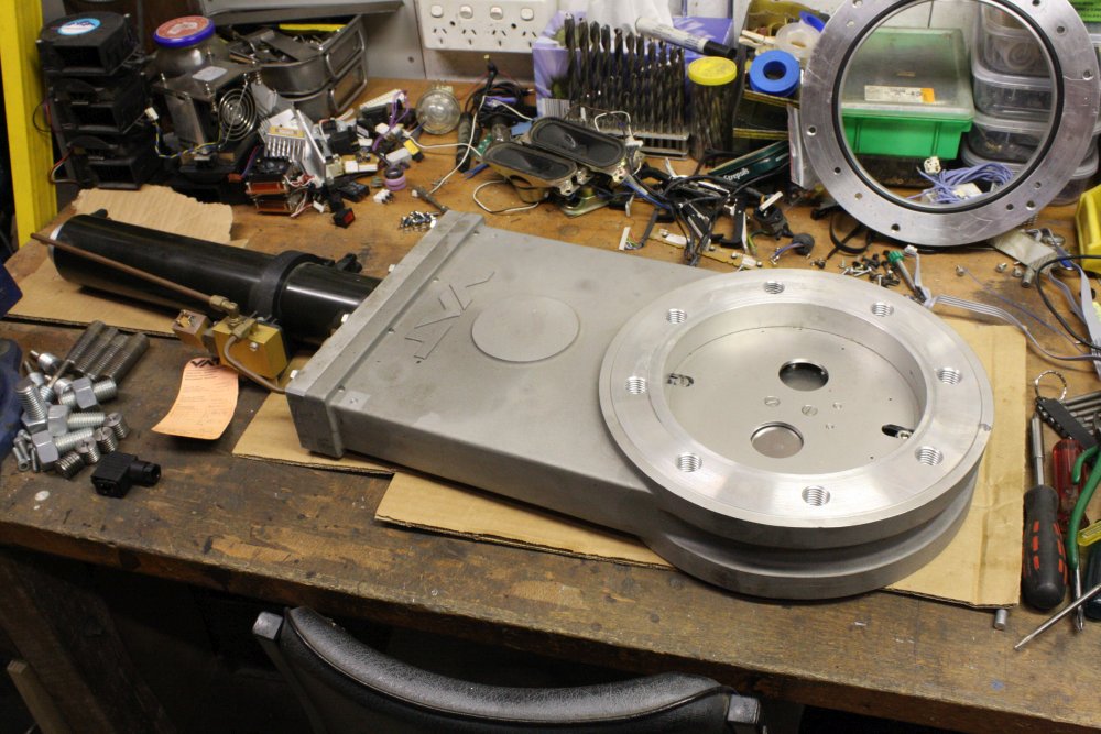
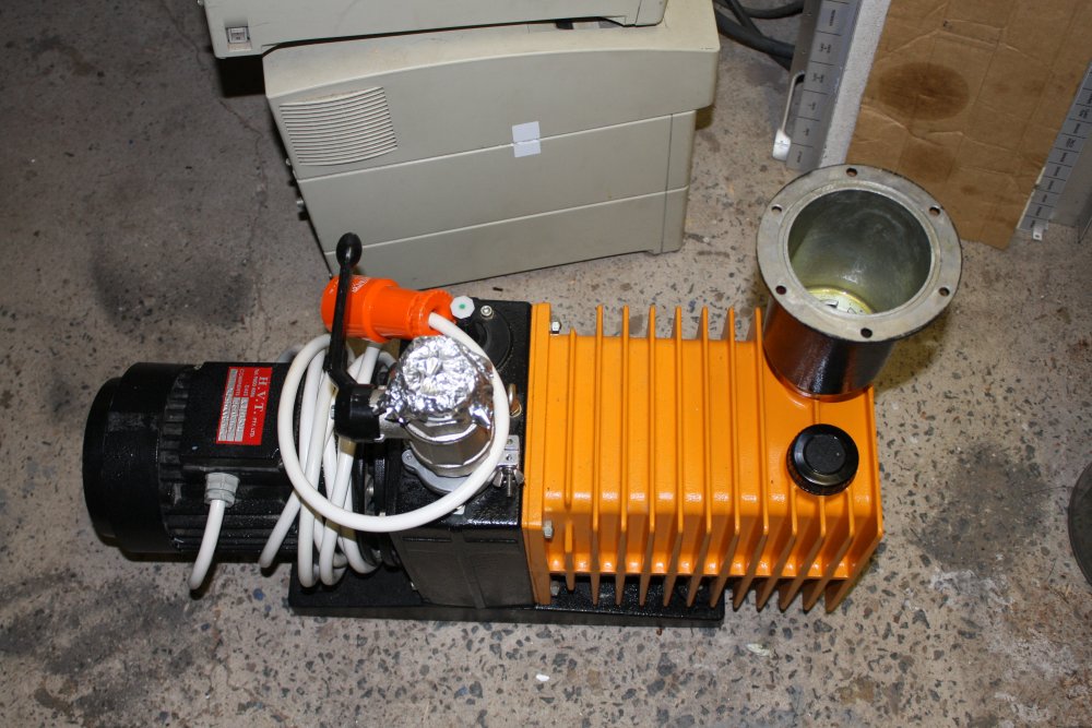
After the equipment windfalls of my January Summer Vacuum Odyssey, the vacuum chamber project is a lot closer to feasible. But there are still plenty of things missing. For instance, assuming one of those large turbomolecular pumps can be got working, there's still the mounting and isolation to do. The turbo pump will attach to the bottom port of the chamber, but a few other things have to go there too. For instance some way to isolate the turbo from the chamber would be nice, so the turbo and associated plumbing can remain at high vacuum while the chamber is opened to atmosphere. A vacuum gate valve would achieve that. Also needed: a means for relatively fine adjustment of gas extraction rate from the chamber when the turbo is connected. Otherwise it's hard to maintain a required gas mix and pressure in the chamber. And like everything else in this experimental setup, I want these parts to be automated.
I'd been given a fairly small manually operated gate valve, and though it was far from ideal I was thinking I'd make do with that. Another thing on the todo list, was to improvise a manifold on the outlet vents of the old and huge vacuum pump mentioned in Rack-mounted Serendipity. Not looking forward to the bodge-job that would require.
And then...
 |
 |
 |
 |
 |
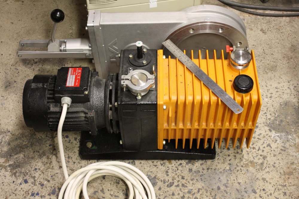
Entirely by chance, in March my Melbourne equipment-angel happened to be given two huge vacuum gate valves, and an enormous rotary vacuum pump with 3-phase motor. He offered them to me. They are awkward things to ship, so in June I drove down to pick them up.
 One day to drive Sydney to Melbourne, the next day to drive back.
They have some curious road safety signs in Victoria. (Story here.)
And, I got a speeding fine. 6 Km/h over in a 110 Km/h zone, $194. Sigh. First one in decades.
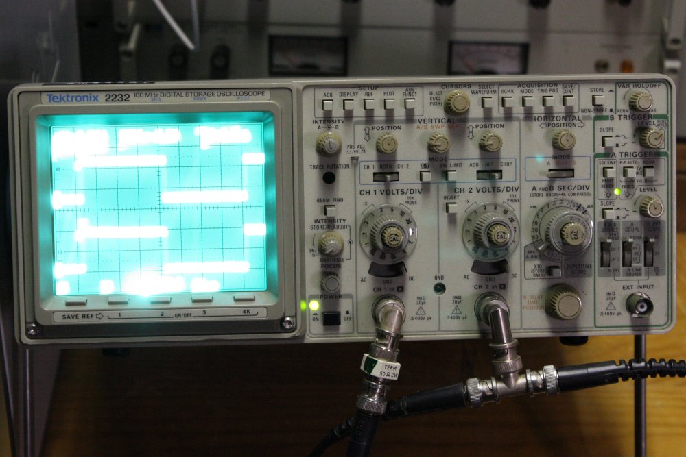
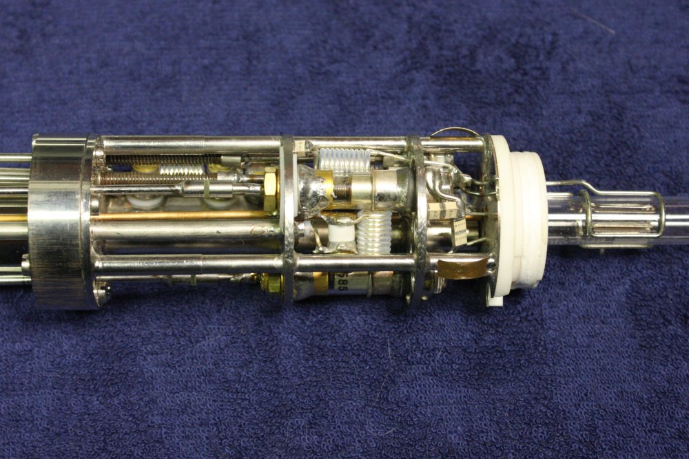
He also tossed in a Tek 2232 oscilloscope (with some problems, including excessive screen brightness, so it's a fixer-upper) and a few bits from a scrapped NMR chemical analysis system. Just one pic of the NMR probe head here. That thing operates at liquid helium temeratures, and a small sample is placed inside the wire antenna coils at right. It's broken (someone tossed it in a dumpster) and therefore useless, but pretty.
Amusingly, when on return I parked next to my workshop to unload, the trip meter was 666.9. (Actually 1666.9 since it had wrapped around.) Photo is after I drove the car back out on the street.
One of the gate valves is air operated, and complete with the pneumatics control valve. It even appears to have hardly been used, if ever. I could not have found a more perfectly suited one if I'd spent thousands (that I don't have) to buy new. Incredible...
It's also amazing and useful that there are two of them, with identical mounting. Since this lets me use the manual one for a metal-working template, hence not scuffing up/contaminating the pneumatic one that I will put on the vacuum chamber.
 |
 |
 |
 |
 |
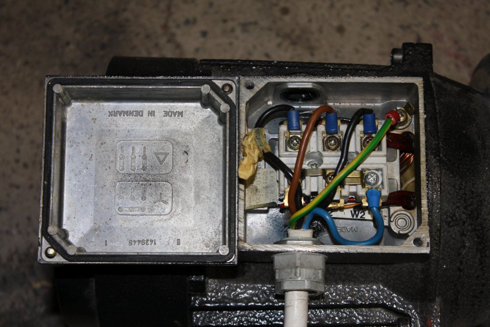
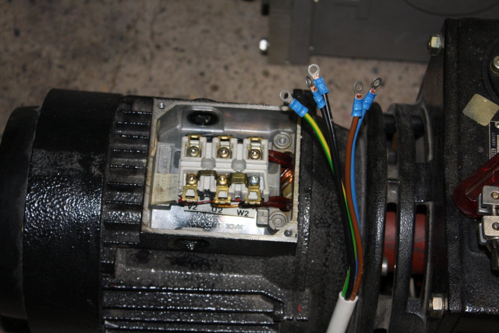
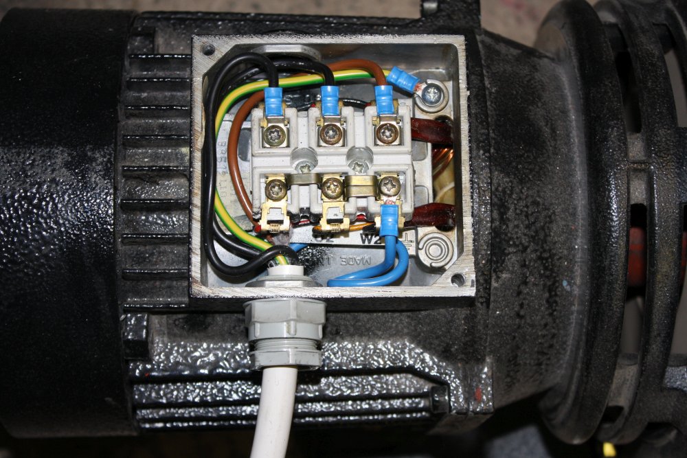
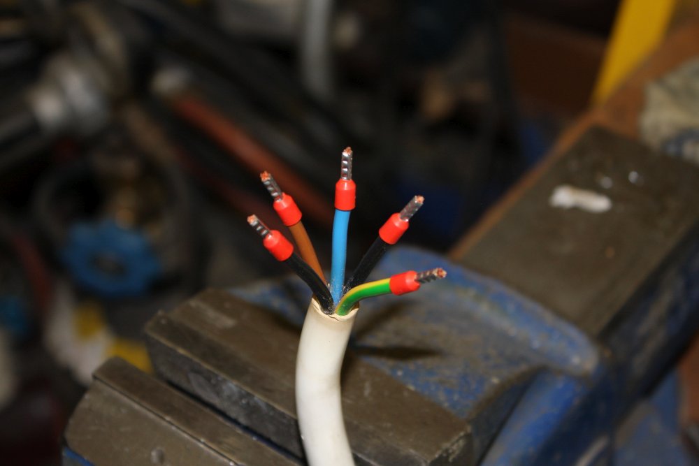
1. The pump 3-phase motor cable had been cut in two, plus the junction box wiring wasn't the best.
2, 3. So I rewired it, using the shorter cable length.
4. Bootlacing the cable ends for the power plug.
5. Completed. It runs, but I'd discovered the outlet oil mist filter is saturated. As a result the over-pressure release operates, so oil mist blows past it. A lot of mist. I only ran it for a few seconds, then held my breath while opening doors to let the oil fog out of the workshop. Definitely do not breathe oil mist from a vacuum pump that was last used in a chemistry lab.
 |
The oil mist filter, that needs fixing.
First step: try to find a source for a new filter element.
That didn't work out so well. The pump is an Alcatel 2033 and Alcatel no longer exist.
Maaaybe I can get a new filter, but they are expensive, with no cheap Chinese source I can find. This pump will only be for rapid roughing, with a smaller pump taking over turbo pump backing. So it doesn't need to be perfection in high vacuum. I tried just cleaning the filter in solvent, and that worked. Not something you'd do for a serious application since the solvent will back-contaminate the pump oil.
 |
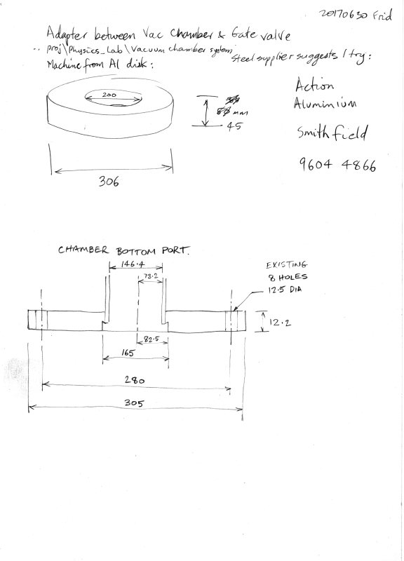 |
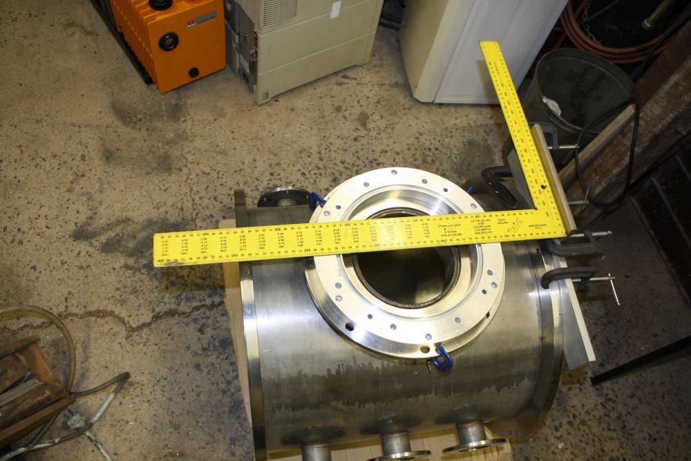
This was one of those rare occasions when it's worth making up some kind of rough plan.
And when I get to the point of machining the permanent spacer ring, there will be a real, carefully done drawing for that. Since it's going to cost quite a bit just for the aluminium blank, then involve some serious machining. No goofs allowed.
 |
 |
 |
 |
 |
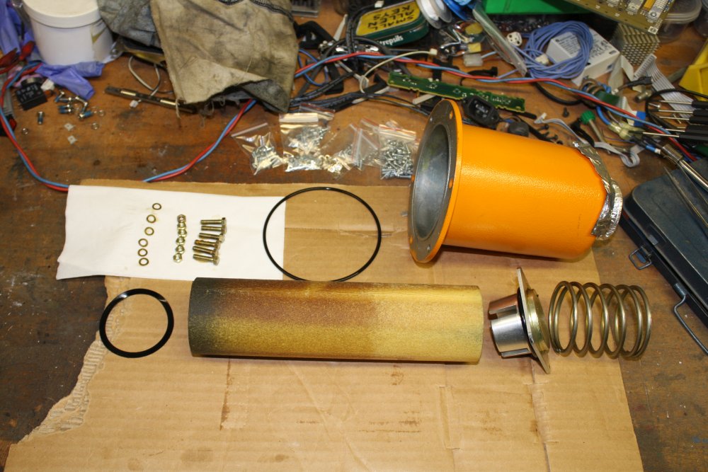
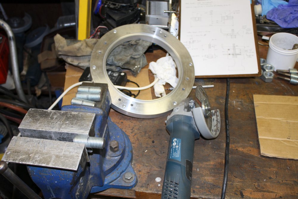
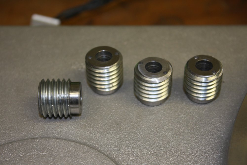
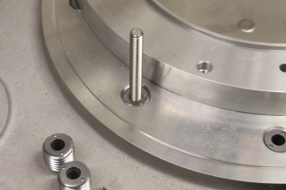
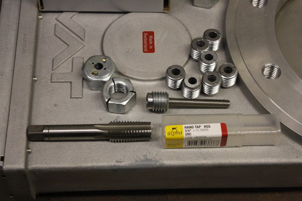
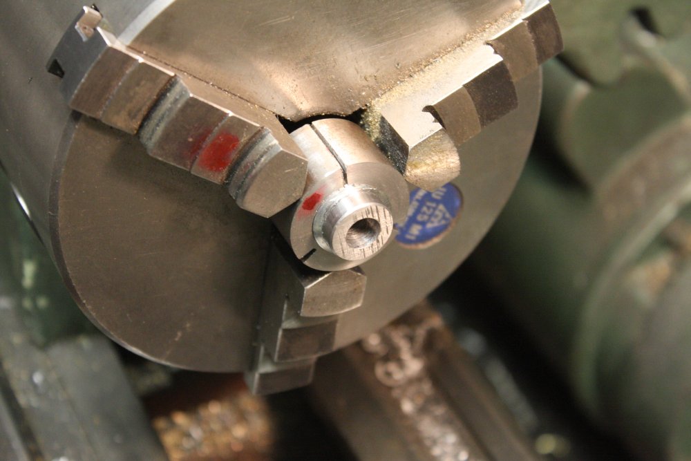
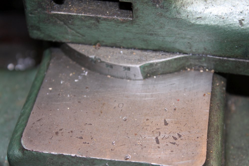
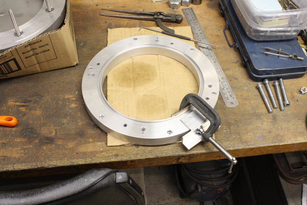
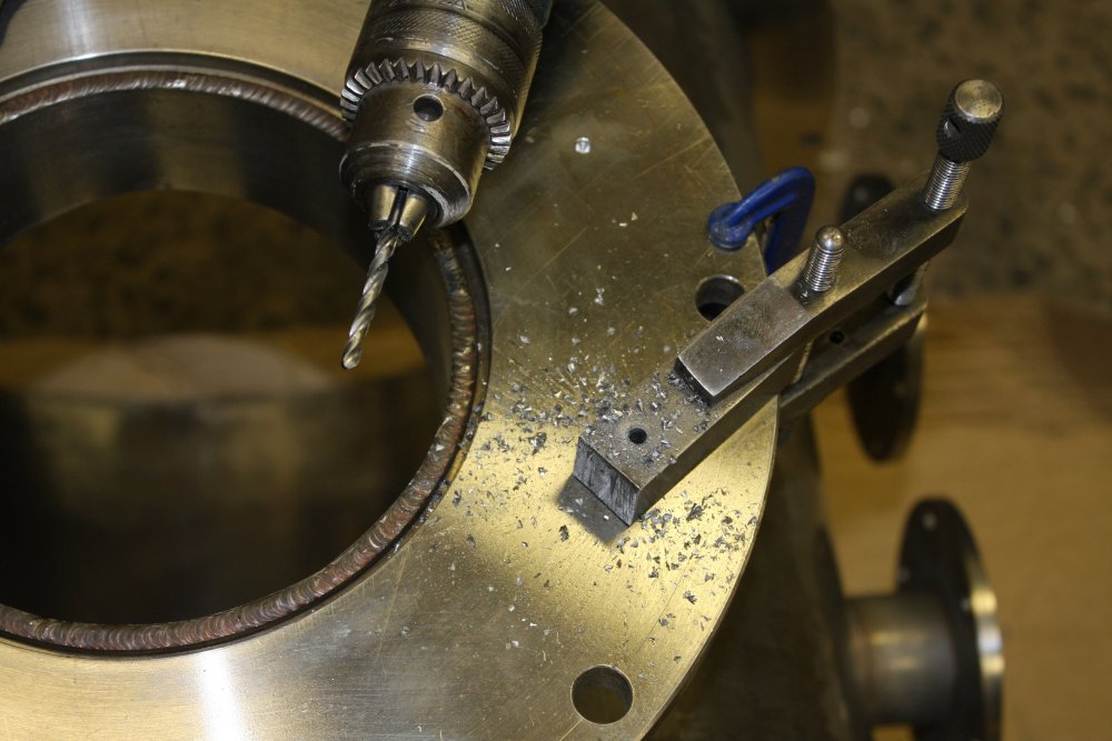
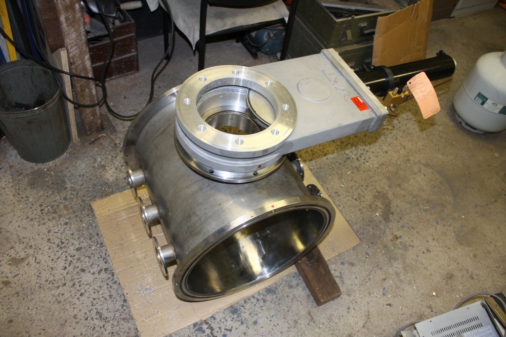
1. For mounting there are 8 blind holes, threaded as 3/4" BSW. It doesn't actually need such huge anchor bolts; these are just meant as attachements for removable studs.
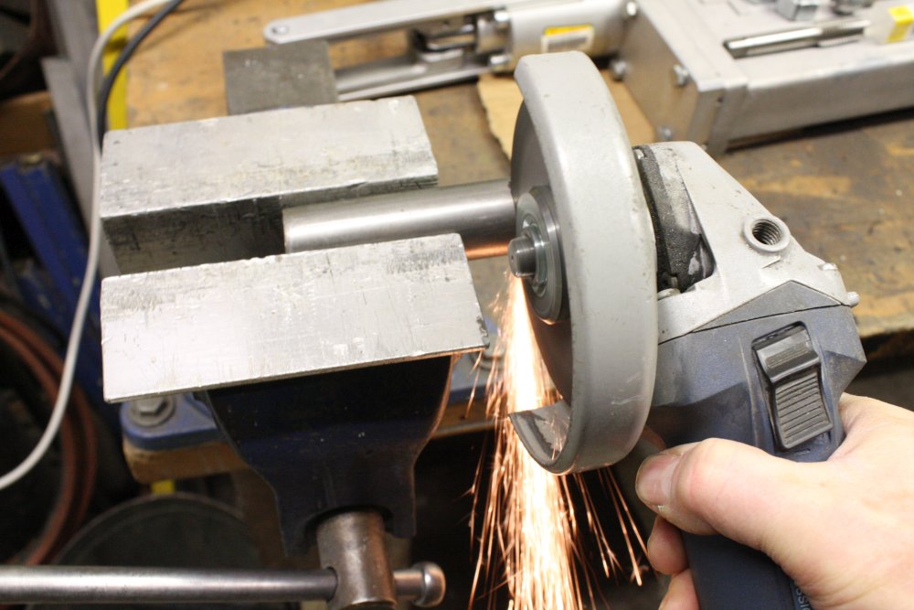
2. The two gate valves came with an adaptor ring (in the background) and an assortment of 3/4" studs. The ring is a bit hacked around, with 'wrong position' holes, and isn't thick enough for what I want to do. But it will serve as a temporary mounting aid. And I can cut up some of those studs to machine the mountings I need. Here about to roughly cut four of them in half with an angle grinder by hand.
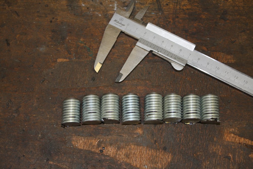
3. Making eight. Should have worked out the exact lengths I needed before halving them, because now I need to do another eight cuts to get close to the right lengths so there is less machining to do in the lathe.
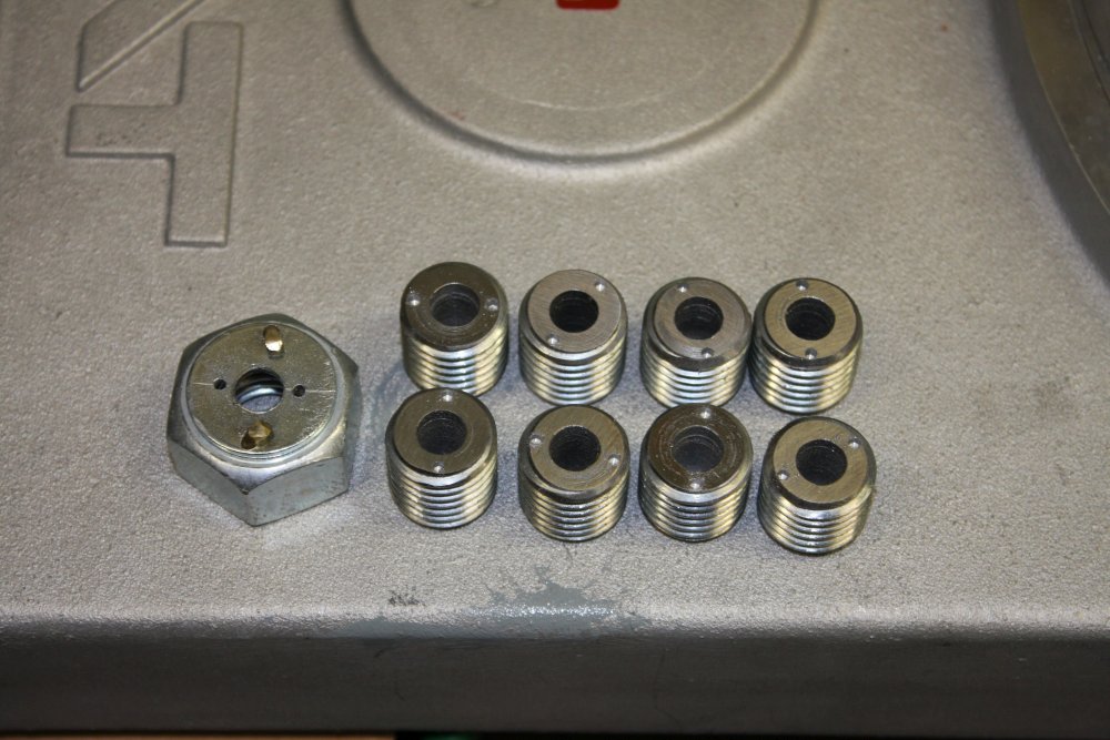
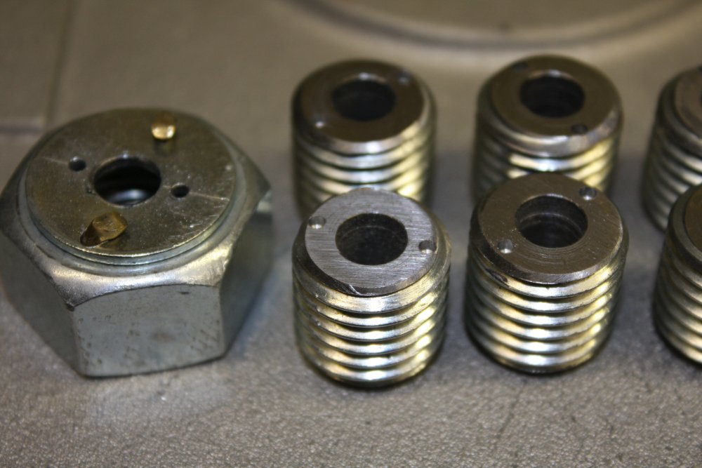
4, 5. After some machining. Since they get screwed down flush into the gate valve stud holes, there has to be a way to unscrew them if they get a bit tight. Hence the pairs of little holes. I can use a pin-spanner, or just pointy long-nosed pliers. To get the holes uniform I made a template using a 3/4" nut, with a drill guide washer pinned on with bits of brass rod bashed into holes as rivets.
 |
 |
 |
 |
 |
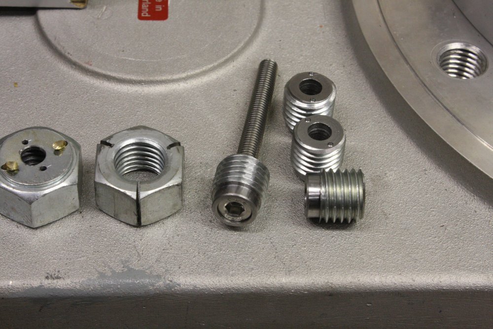
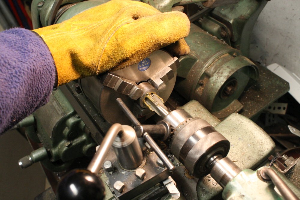
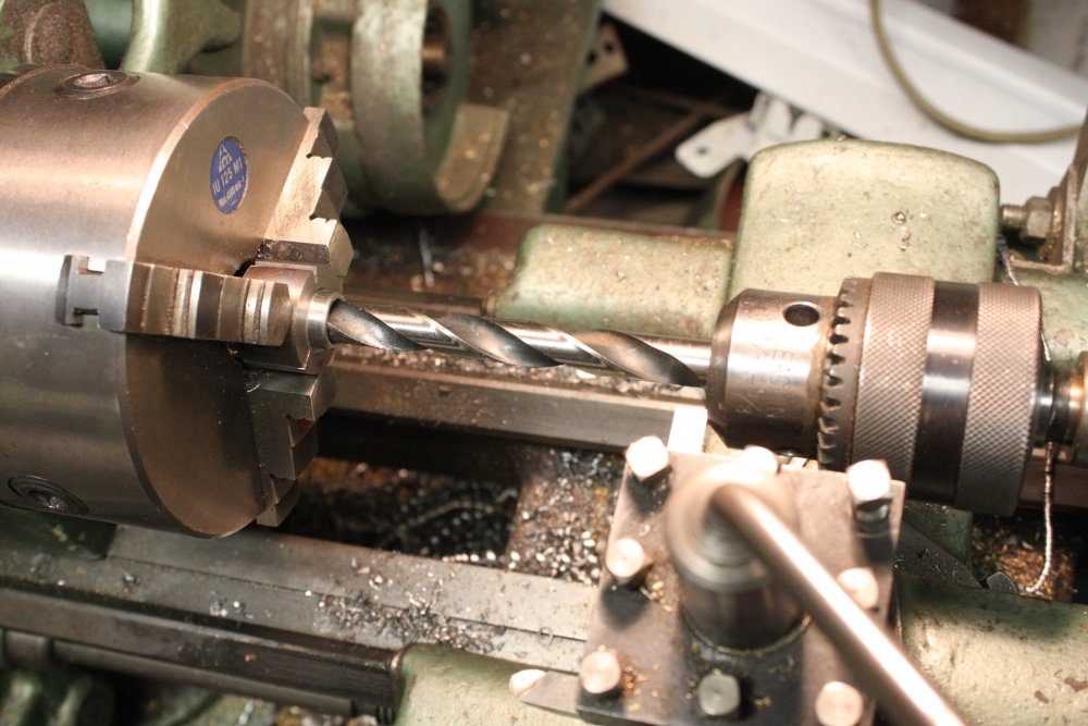
1. Since of course the threads in the gate valve stud holes don't go perfectly all the way to the hole bottom, there has to be a rebate on these plug threads. Grabbing threaded pieces in the lathe chuck isn't good for the threads, and after this machining step I'd had to carefully file back the resulting thread dings with a tiny triangular file by hand. Far from ideal, and a problem that needs a solution since I have more machining to do on them.
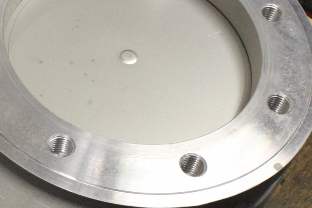
2. Just a quick sanity check. The bolts are M8, and just resting loose in the holes of four of those plugs. Note here you can see a flaw in the aluminium disk. Instead of the 8 mounting holes being evenly distributed around a circle, four of them are rotated and not equi-distant between the other four. Maybe a machinist misread the drawing, or maybe the drawing was stupid — which is more likely since otherwise the ring would have been sent back to the machine shop to be fixed. I bet someone was cursing themselves when the ring was delivered and they discovered the goof.
Anyway, I'll be drilling holes in the right places.
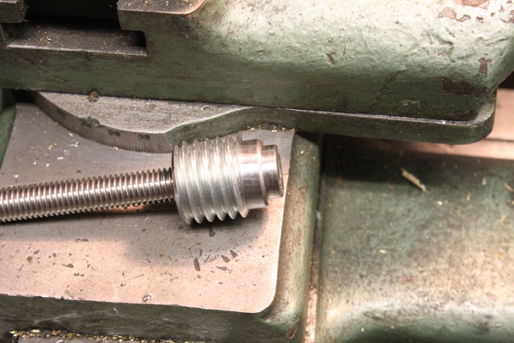
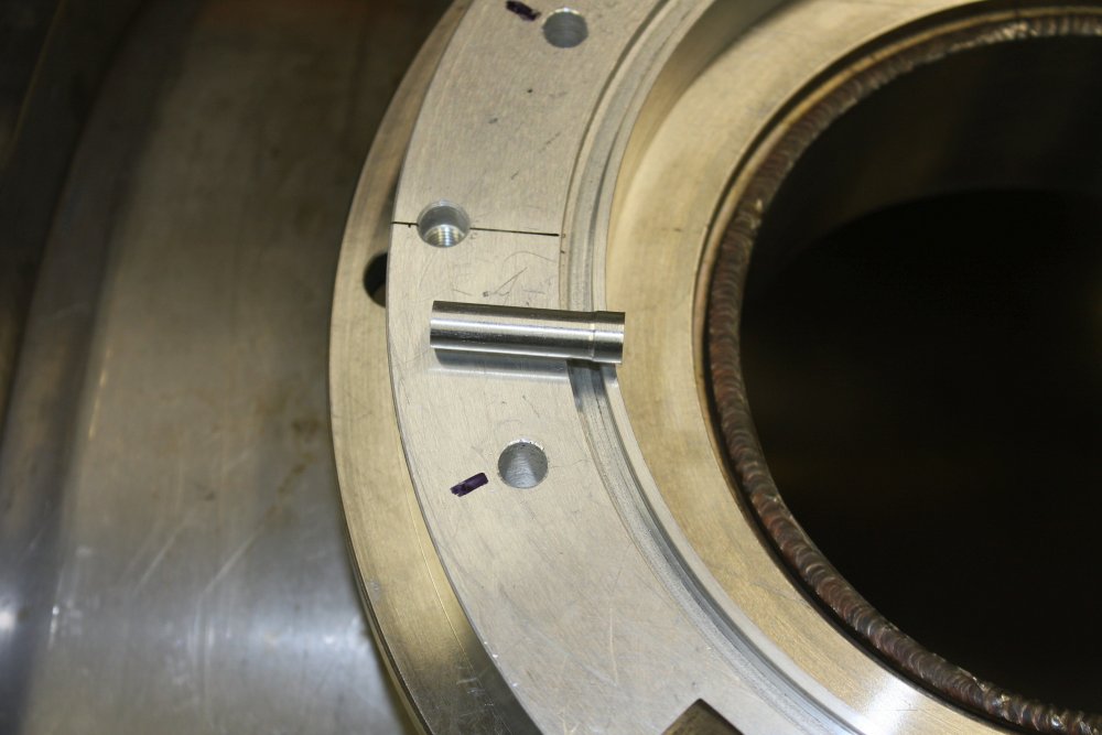
3, 4, 5. Those bolts were 'upside down.' What the mounting needs is studs sticking up from the gate valve. Here's how they are fixed to the threaded plugs. Drill a hole in the plug a little smaller than the round machine screw head, then machine the head to a slightly tapered size that can be pressed tightly into the plug. Bought some nice stainless bolts then first made just one to check the principle. It works. This time rather than clamp the threaded plug in the lathe chuck and damage the threads more, I tried using a nut with slots cut so the chuck could compress the nut onto the plug. It worked, but the nut threading isn't centered accurately, so the plug can't be repeatedly centered in the chuck.
Why do they have to be studs sticking up, rather than bolts dropped down into the holes? You'll see later.
 |
 |
 |
 |
 |
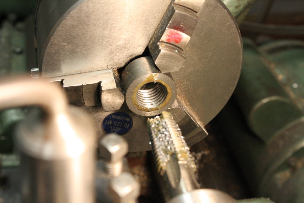
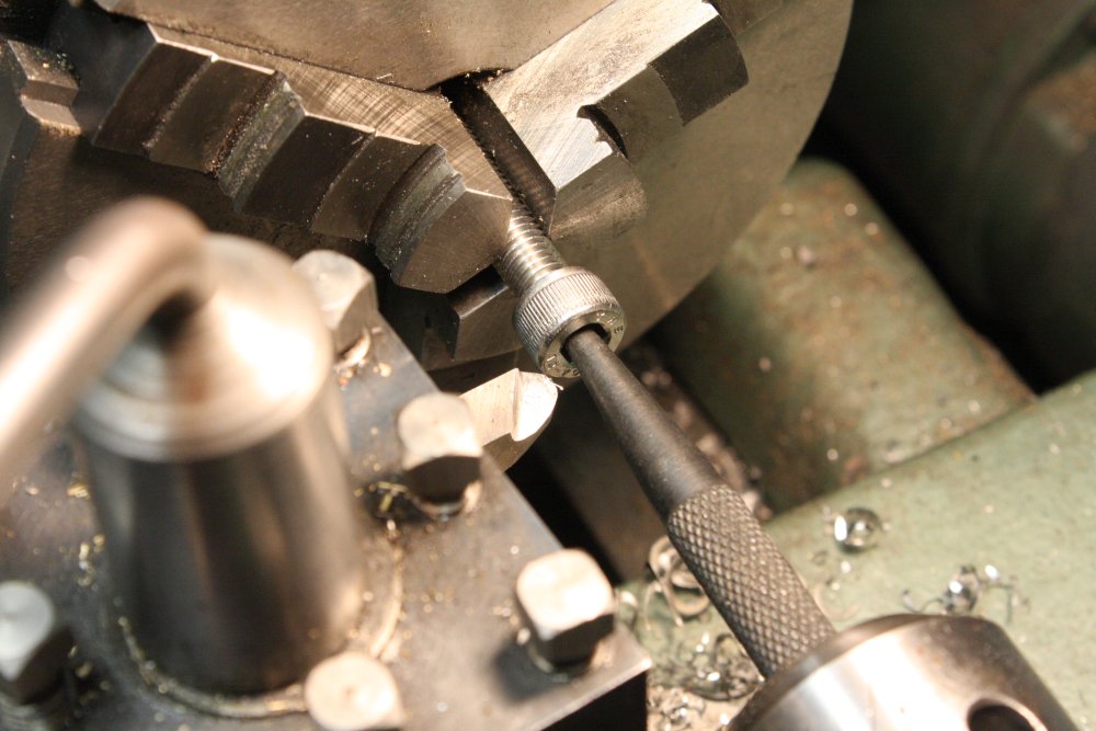
1. I needed a better machining solution than that rough slotted 3/4" nut. Something that centered the plug properly, since any inaccuracy would affect the axial alignment of the stud bolts. Any misalignment would make assembling the gatevalve to the vacuum chamber a pain.
First step was to buy a 3/4" BSW taper tap. Yes, it is expensive.
2. Then cut off a bit of round bar, that will be the well-centered 'nut'.
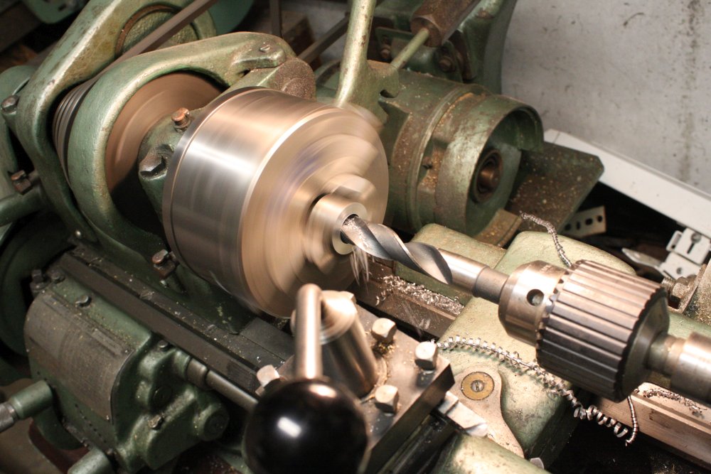
3. After machining the ends flat, and center-drilling a start hole in one end, drill right through it with a size to suit threading it for 3/4" BSW.
4. Then use the lathe for alignment only, start hand tapping the hole. The lathe chuck is set to spin freely, while the tapping bit is locked. It takes a lot of force to drive the tap, so much that I needed to use gloves to apply enough torque to the chuck. Also the morse taper locking the tap isn't enough to prevent the tailstock chuck from slipping, so I started out using a chuck key wedged against the tool head to prevent the tailstock chuck from rotating.
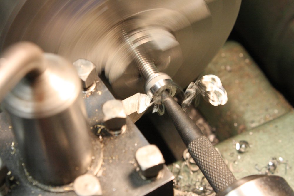
5. Except you have to work the tap back and forth to break off shavings as you go. I needed to lock the tailstock chuck in both directions, so upgraded to this pin that you can see resting in the tool head slot.
 |
 |
 |
 |
 |
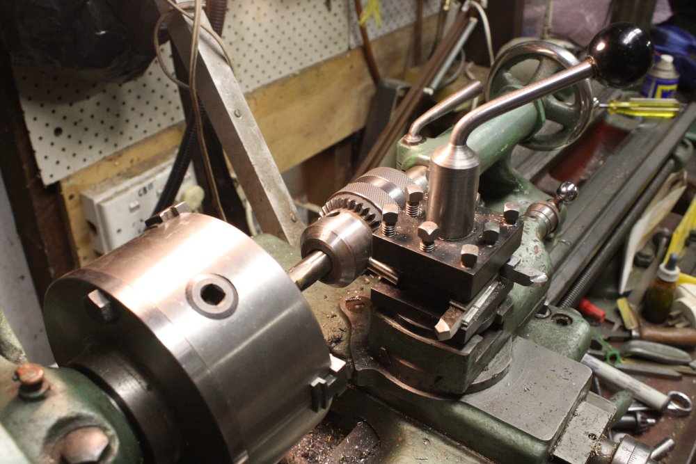
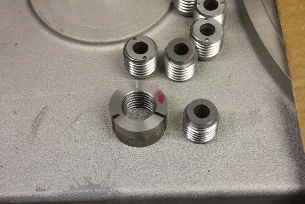
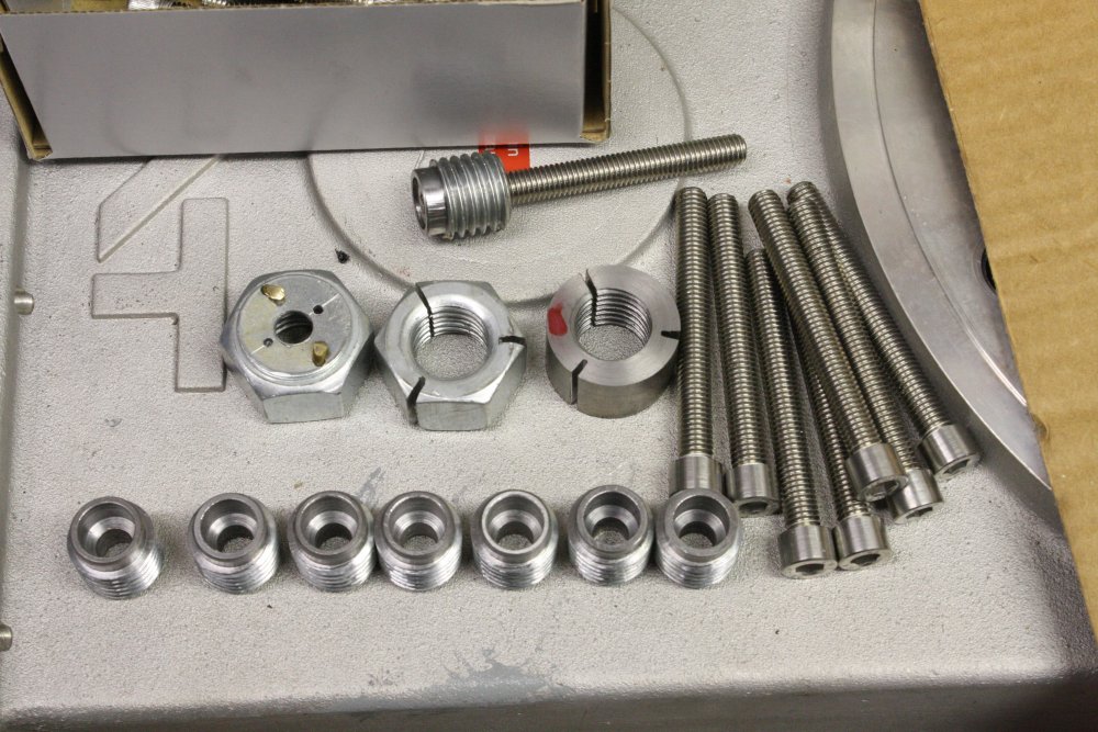
1. Threading done.
2. The round 'nut' slotted so it can compress onto the plugs in the lathe chuck.
3. In place in the lathe chuck. This works very well. Red dots are for repeatability.
4. Drilling the housing for the bolt heads. Not very visible: a cutting tool bit clamped in the tool post, being used as an end-stop against the tailstock chuck front face, for hole depth.
5. All of them done. (Well, except that I'll likely have to do another eight for the other side of the gate valve later. But I'm not yet certain how the turbo pump will be mounted, so left those for now.)
 |
 |
 |
 |
 |
1. Setting up to do the taper cut on the bolt heads. The punch held in the tailstock chuck is to give a repeatable position of the bolt head. Which matters because the tool post slide is set to one degree of taper.
2. Cutting a head. A nice sharp silversteel cutting bit gets a good finish on the stainless. I had set up the depth of cut by iteratively shaving a bit, then taking the bolt out and trying the fit in the plug end hole. Once correct, with everything on the lathe locked and using only the small taper slide, just drop new bolts into the chuck against the punch as an end stop, and cut.
3. One degree of taper, in the opposite direction to normal. Sorry the pic is a bit blurry.
4. Here's where the bolt heads rest when finger-tight in the plugs. Before bashing them down with a hammer.
5. All of them cut, ready for bashing.
 |
 |
 |
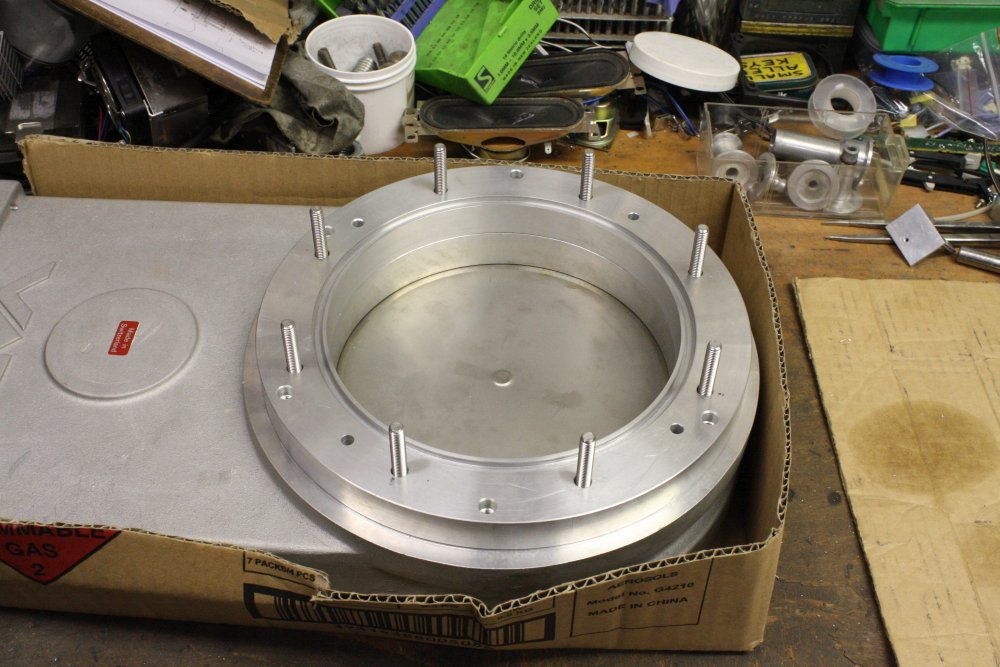 |
1. Tiny one degree taper is tiny. It doesn't take much to push them down. But once down they are not coming loose easily.
2. All in place.
3. Now to deal with those stupidly misplaced holes. This is a template to get the hole positions accurate radially. I could have been a bit more careful with their angular position. It was a bit awkward since I used a compass to mark 'half way' points between the original 'correct' holes, but it was obvious those were not all that accurately positioned either.
4. Anyway, the result fitted, though with a little bit of side-scraping and pushing.
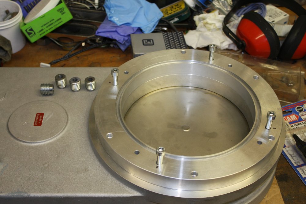
Note that I won't actually be using this spacer ring in the final assembly. It isn't thick enough for some large radial holes needed here, for vacuum pumping, metering pipes and signal feed-throughs. Those have to go in the ring in this place, since I am not going to be cutting any holes in walls of the large, irreplaceable stainless vacuum chamber. I want to keep the existing chamber side ports free for other uses. This particular ring is serving only as a test assembly, and is about to be a drill template.
 |
 |
 |
 |
 |
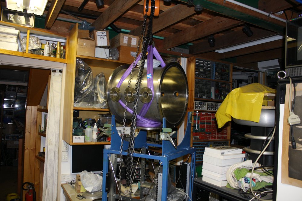
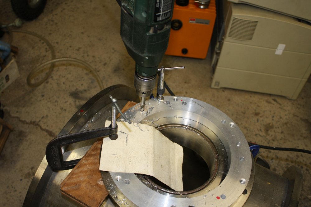
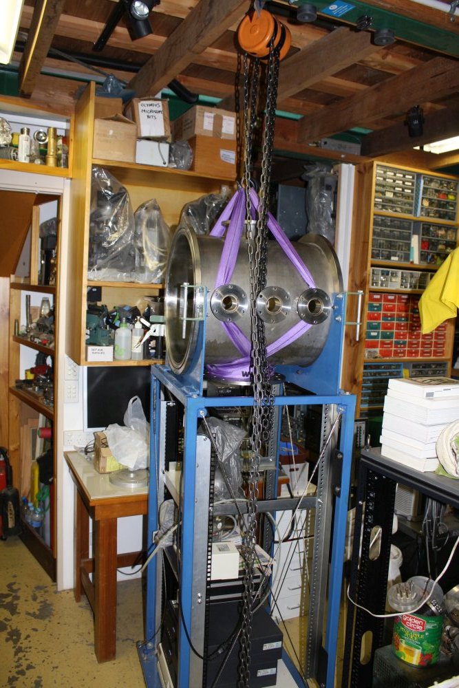
1. A drill template is needed, since of course the stud positions of this gate valve do not match the existing flange holes in the lower port of the vacuum chamber. I'm going to have to drill eight large holes through that thick stainless steel flange. By hand, since it's too big to fit in the drill press. Oh boy.
So, the vacuum chamber has to be demounted and moved to the machine workshop. For this a winch is essential.
2. Relocated.
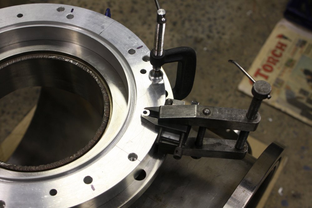
3. The small g-clamps on the flange are to hold the ring centered. Here using a square and flats clamped to the chamber end seal to get the angular positioning right. I'd like the gate valve to be square to the chamber.
Annnd... in this pic you are looking at a dumb mistake I made, but didn't notice at this point. Can you guess?
It's not the 'extra' holes. Those are all 'previous owner' and their mounting efforts. Extra holes are harmless, since they are all outside the vacuum sealing rings.
4. Next, to actually drill holes through the stainless steel. First I'll make some small starter holes, using the template. But since these have to be small and I don't want to wear the template holes larger, I made a drill positioning sleeve in the lathe. (There's a hole through the middle, matching the small drill bit.)
5. For drilling, that sleeve is clamped so it doesn't rotate.
 |
 |
 |
 |
 |
1. Starter holes done. They are only a few mm deep.
2. Next to run them all the way through. A small drill like this can be pushed through stainless steel by hand, but not a larger sized drill, since there's an area at the point of the drill where material has to be pushed aside by sheer force. With a small pilot hole in place, the larger drill bit does not have to do that, so much less force is required.
But the pilot holes have to be accurately vertical, which is nearly impossible to get right by hand. Hence this improvised alignment tool.
3. At around this point I realized my mistake back in the previous row. There was some cursing and hacking before this photo.
Notice the aluminium ring is the other way up in this pic? That o-ring seal is only on one face, and it has to go this way up. Not the way I had it in the previous few pics when drilling the pilot holes. That way was wrong. And when I realised and flipped it over, some of those nice neat pilot holes don't quite match the holes in the flipped-over disk. Not much off center, just enough to be bad. This underlined that the original 4 holes, and hence my added 4 which were referenced to them, were not as accurate as they could have been. Some hole sideways filing and then drilling them all out to a slightly larger clearance later, I was satisfied that the ring holes were now on-center to match the gate valve studs. Which are of course accurately spaced.
But that leaves this thick stainless steel flange with small pilot holes all the way through, three of which are very slightly 'off'. Shit.
Oh well. This ring is supposed to be temporary and a template anyway. So I just clamped it firmly, and used it as an alignment guide to drill the full sized holes through the stainless. Using an 8.5mm drill, the steering provided by the thick aluminium was enough to override the slightly misaligned pilot holes. The swarf from the stainless cutting tears up the inside of the holes in the aluminium ring somewhat, but it doesn't matter.
This stage took quite a while. Hand drilling 8mm holes in 12.2mm thick stainless, is slow going. As always with stainless it's essential to run the cutting tool fairly slow but with continuous firm pressure, to avoid heating and work hardening the stainless. So it's some effort.
The piece of hardwood clamped to the flange back, is so when the drill breaks through it doesn't drop down and damage the close-by fairly thin wall of the vacuum chamber. Yeah, I'm sometimes able to spot potential goofs before they happen. (Still feeling pissed off with myself for the disk-flip plus inadequate checking of hole alignment mistake.)
4, 5. All 8 holes drilled. Phew.
 |
 |
 |
 |
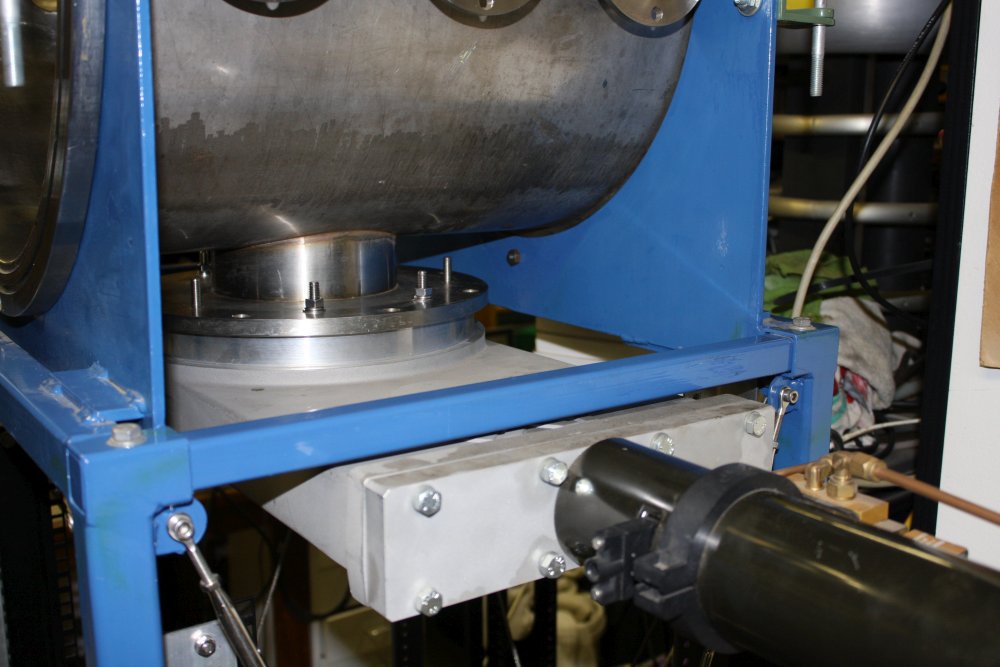 |
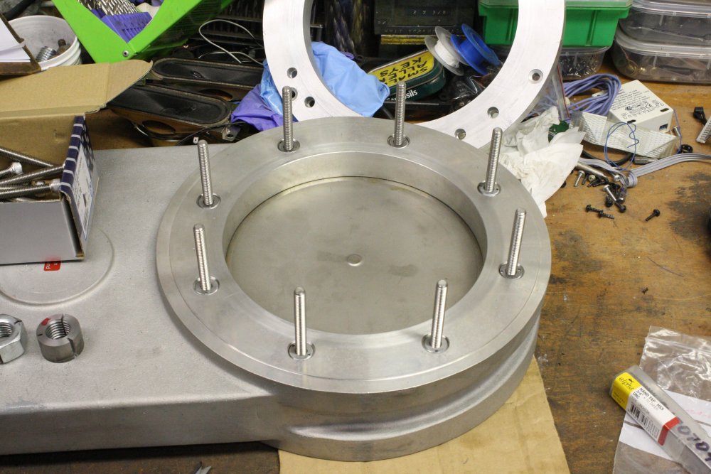
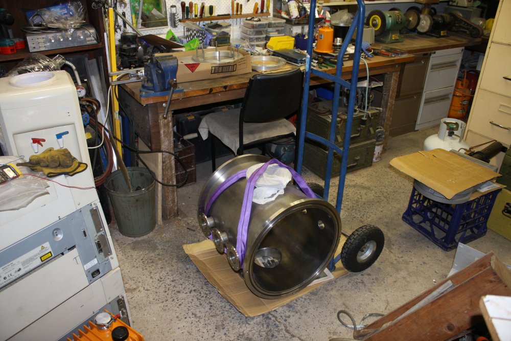
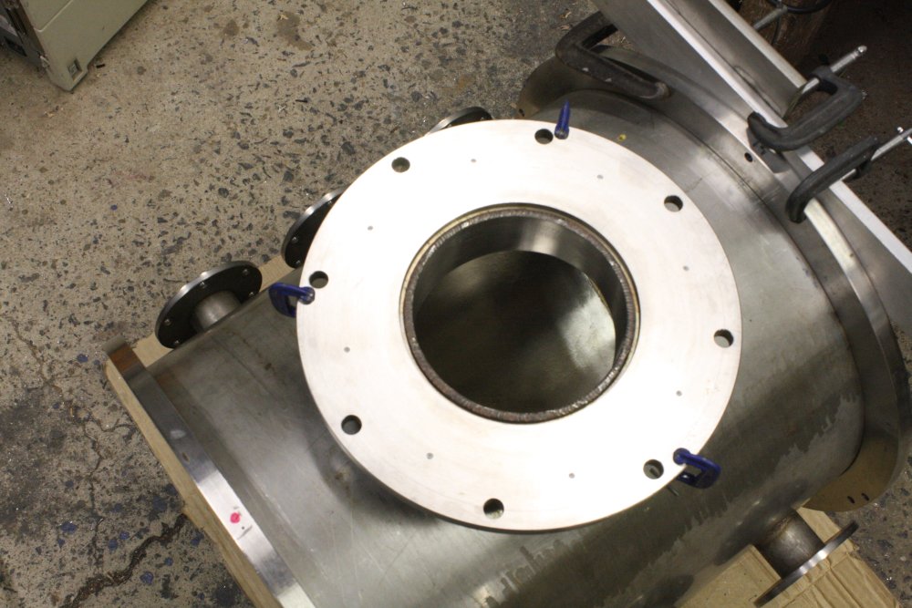
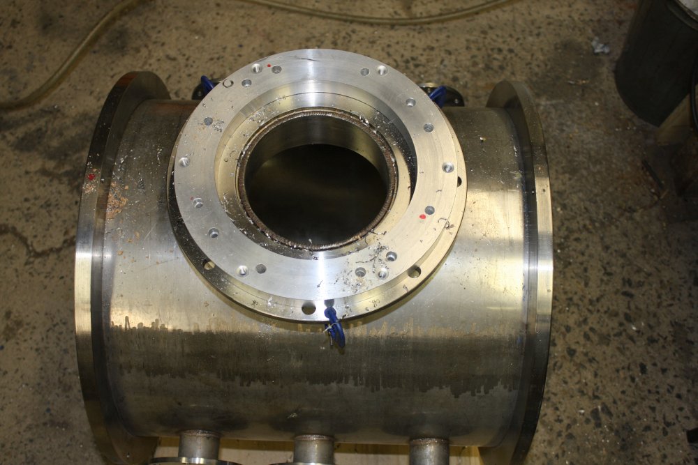
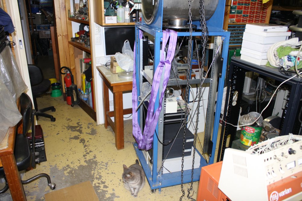
1. Much to my relief, the gate valve and spacer disk slip together easily. Reassembling this right way up in the frame will require holding the heavy gate valve up by hand while getting the first few nuts on. Don't want to have to fight with poorly aligned bolts vs holes at the same time.
2. Mounting it back on the stand. I'd set myself up with another slight goof here, but this time harmless and amusing.
3. While the chamber was on the floor, I'd run the lifting sling around it, I thought the same way I'd done it the first time. But somehow I got the topology wrong, and when removing the sling once the chamber was bolted in place, found I'd created an unremovable loop.
My gray cat Tiny is looking down in shame at how stupid her human is.
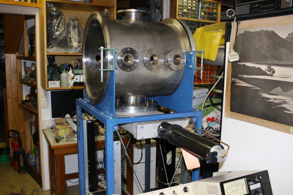
4, 5. Easily fixed. Here the pneumatic gate valve is mounted. It's all temporary, no vacuum seals in place yet.
The remaining problem is that the side weight of the gate valve has to be supported, since at the moment it's all bearing on the chamber lower port pipe and its welds. Not a good idea.
These photos also show why the fasteners have to be studs, not bolts slipped into the holes. Because there is not enough clearance between the chamber body and the flange to slip long bolts into some of the holes.
 |
 |
 |
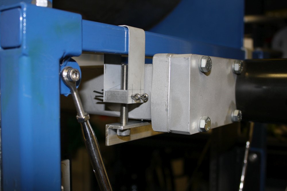 |
There needs to be something to attach the valve side to the horizontal frame above it. Keeping in mind that:
- With a thicker aluminium spacer ring in future, the gate valve will be lower. But I want the support to work now too.
- The support needs to be adjustable, to take up the right amount of weight.
- Don't make any alterations to the existing frame. Or the gate valve.
- It has to be easily removable without taking anything else apart.
- Easy to make.
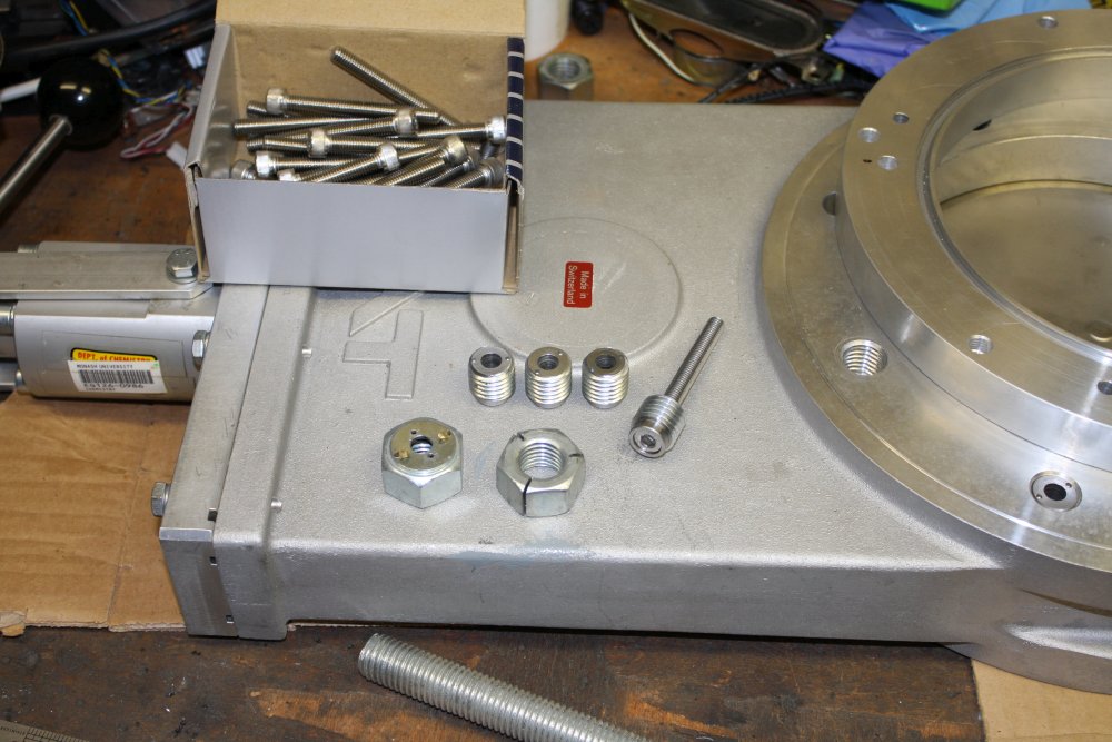
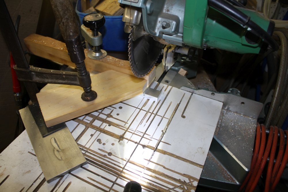
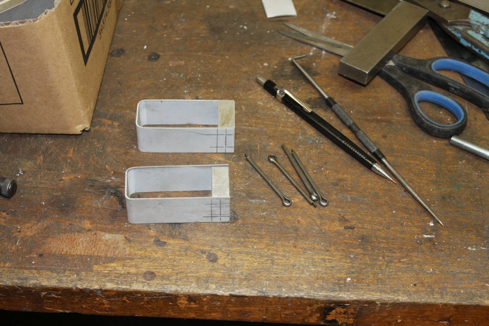
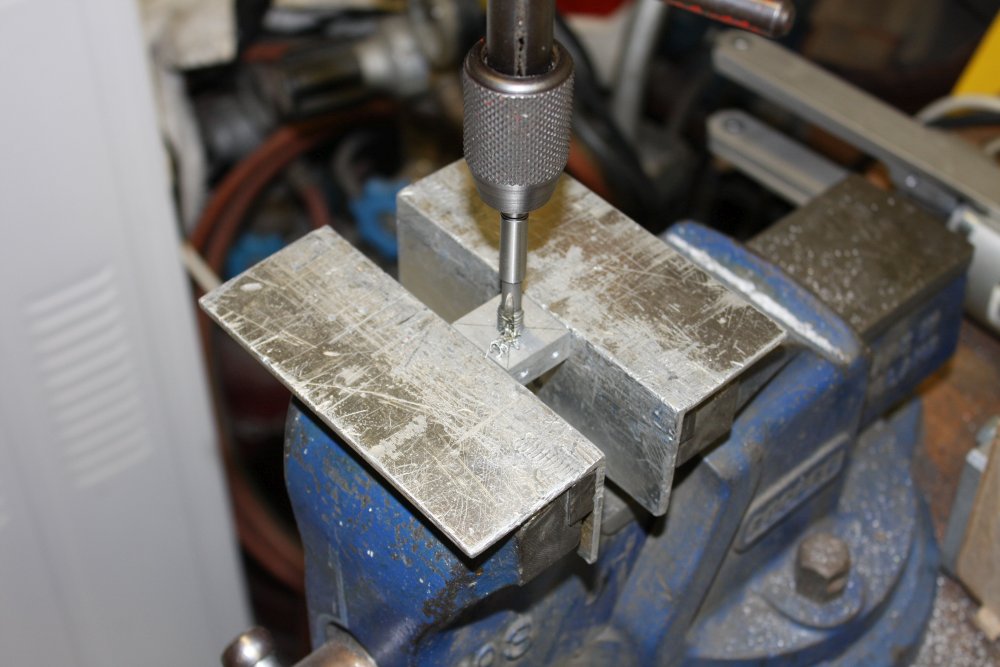
1. Cutting a couple of aluminium blocks. For cutting small pieces like this, clamping arrangements are 80% of the work.
2. A couple of small aluminium strips cut and folded over a scrap bit of bar the same as in the chamber stand. Plus some split pins.
3. Tapping. I'll use the same stainless bolts as I bought for the studs.
4. Mounted. That works nicely.
That's all for now. There's much more to do, and some of it I'll post here as things progress.
One major problem is that I need to machine the new spacer ring of aluminium, and the size is too large to do on my lathe. Options are: paying to get it made, borrowing time on someone else's lathe, or maybe even getting myself a bigger lathe. (This time, metric!)
 There's a lot of vacuum plumbing and other stuff to do too.
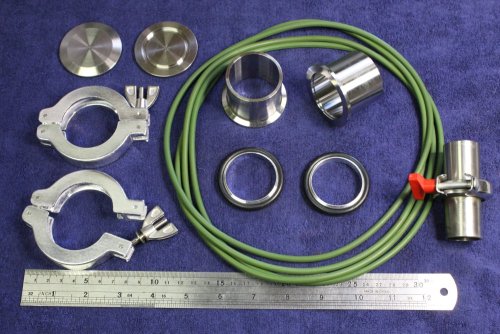
Various bits and pieces to buy, like these large viton O-rings, and KF-40 vacuum fittings.
The large vacuum pump oil mist filter is now working. Ha ha, the pump has KF-40 (40mm dia) fittings. With ordinary small vacuum pumps, a simple suction check is to put a finger on the inlet port. When I got this huge one working without spewing oily mist, I was about to do that, then caught myself. Uh, no, putting one's palm over a 40mm inside-diameter pipe, that goes near instantly to full vacuum is not a good idea. It might not hurt toooo much. But I think I'll forgo that test.
20170811
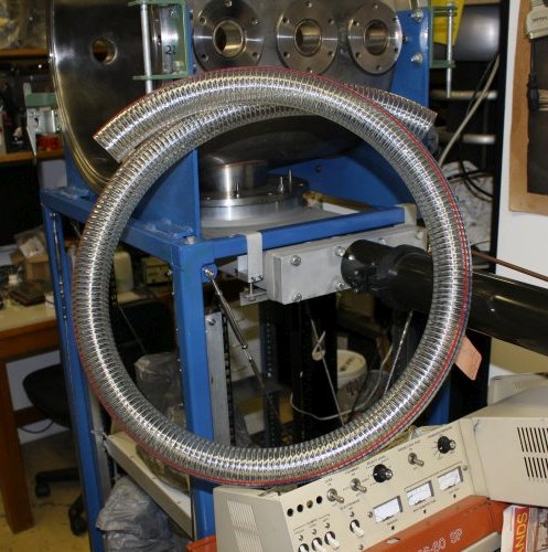
Two increments forward, one back.I couldn't find vacuum hose to fit those KF40 nipples in the pic above. Only this hose, which is 38mm ID, instead of the 45mm ID I wanted. And it definitely does not stretch to fit, due to the steel spiral wire embedded in the plastic. (That's what stops it collapsing flat under vacuum.)
Oh well. Now I'll have to machine an aluminium KF40 fitting to suit at one end. The other end was going to require machining anyway, since this tube has to fit the pipes of an old pneumatic vacuum bellows valve.
This is about 1.9m of hose, which cost Au$46.