The usual state of my various projects is "stalled, waiting for something or other." Where 'something' can include Life's Little Detours (cue hollow laugher), dependency on some other project completing, finding things that are unobtainium or stuff I can't afford, through to inspiration about how to solve some problem. (Inspiration can be elusive too.)
Near the apex of my resulting pyramid of stalls and holdups, is a cluster of equipment racks collectively intended for some pottering with nothing. Vacuum, to be precise.
This project goes very slowly. Despite some excellent assistances from Lady Luck, my relationship with her is complicated and I thought I'd worn out her generosity. On which I'm somewhat dependent since commercial equipment of the types needed tends to be multiple orders of magnitude beyond my financial resources, and improvising things from junk can only go so far.
 One of the remaining needs, was a high vacuum pumping system.
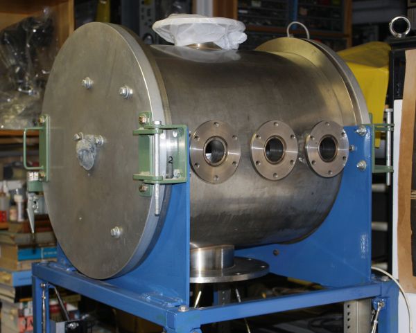
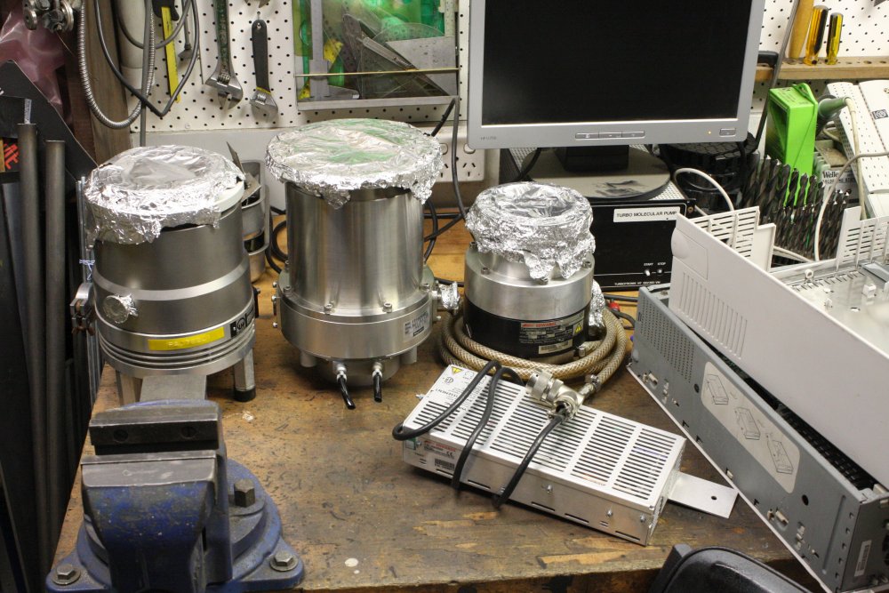
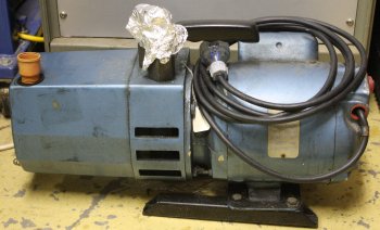
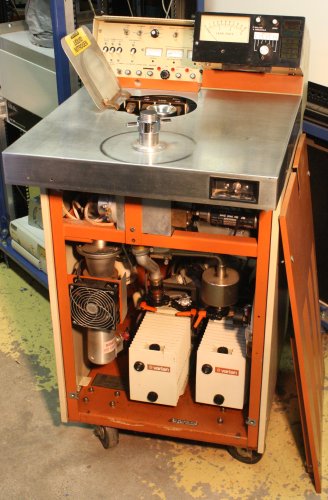
The large vacuum vacuum chamber (at left) was a lucky gift, and it came with a huge oil diffusion pump (below), mated to the chamber via a large gate valve and improvised water-cooled oil-backstreaming baffle. Also a couple of rotary roughing pumps among other things.
 |
 |
(Dust cover removed for photos.)
Oil diffusion pumps though, are a pain. It's nearly impossible to stop the oil vapor from getting into the vacuum chamber and condensing on everything. In general they have very slow on-off cycle times, and with a huge one like this I don't even want to know how long it could take to get up to operating temperature, and then back down. The oil used is expensive, they generate a lot of heat, most (like this one) require a water cooling loop, and if you make a sequencing mistake and let air into the system while the oil is hot, it can catch fire or explode (and has to be replaced.)
Not to mention that this thing is huge, and takes up virtually all the space in the stand under the vacuum chamber. I really didn't want to use it.
The alternative is a turbomolecular pump. Slight problem — I don't have one, and they are hideously expensive. Even for unknown condition ones on ebay, the prices are ridiculous. See for yourself.
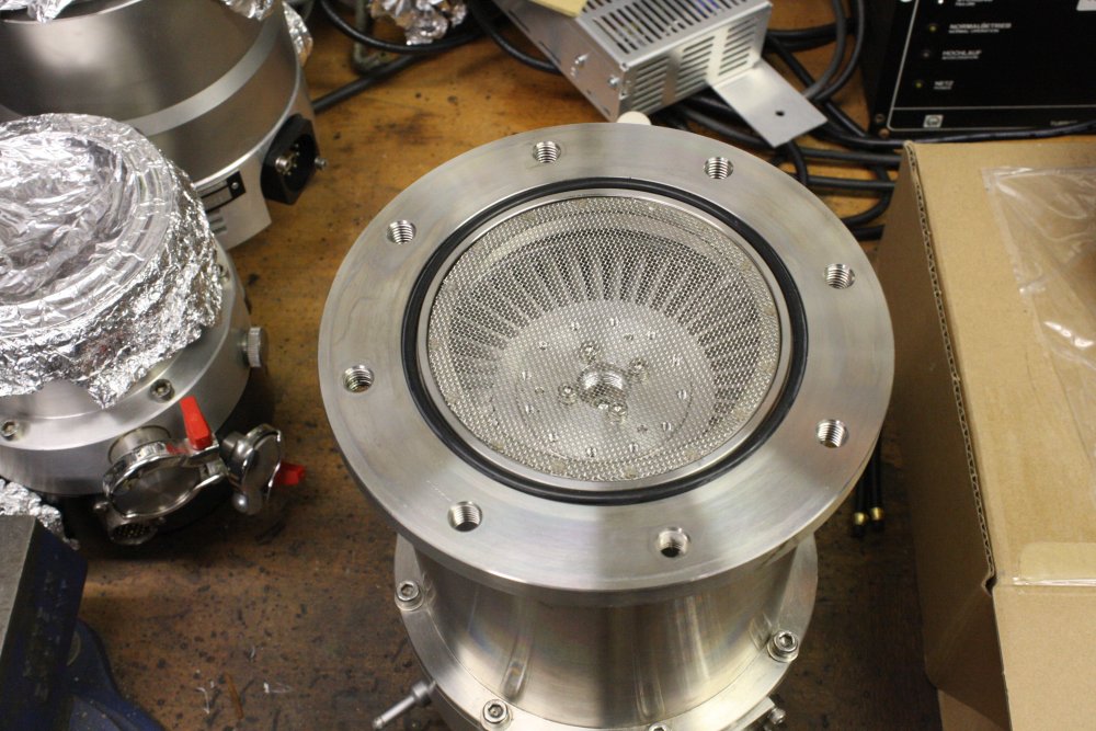
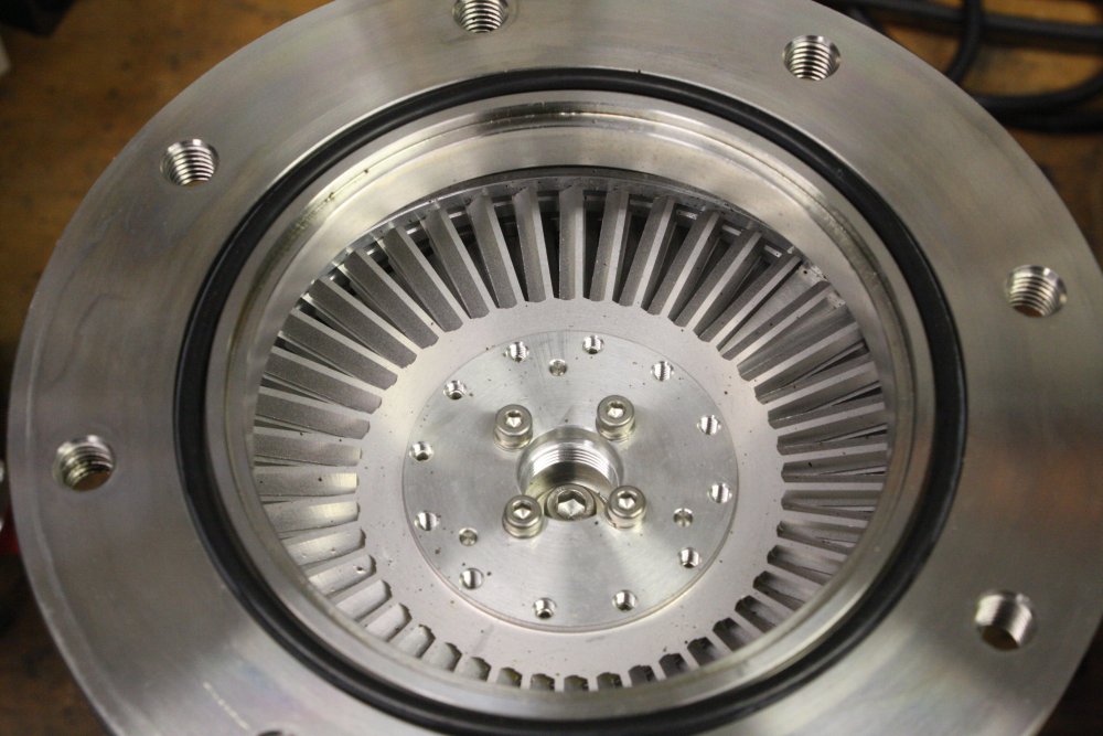
Heck, even for completely wrecked beyond repair ones, the prices are still ridiculous. I don't know why this is, maybe it's just the 'it's hi-tech and shiny, better charge a lot' factor. From sellers who have no idea. And most of them do seem to have no idea. You can tell, because any photo of a turbomolecular pump sitting around without a dust cap on its inlet port (large one, usually on top, with the internal blades visible), is a photo of a turbo-pump being ruined by allowing dust to settle into it. Also they all require a controller module to spin the motor (typical speeds well above 20,000 RPM), and notice that most of the turbo pumps on ebay are missing the crucial controller and interconnect cable.
Well, I was busy with other things anyway. I decided to just wait and see what turned up, while I worked on other parts of the system. That was quite a few years ago. By now the lack of a turbo pump has developed into a critical wedge.
Almost but Not Quite
I'd had a few near misses. One time a friend who worked at Garden Island (Sydney's naval base) mentioned to me that the base's Vacuum Systems Lab had just shut down, and everything from there had been tossed into dumpsters and disposed of (destination unknown.) Just a few days ago by the time he told me. He started describing the mountains of gear, vacuum plumbing, etc, but I asked him to stop.
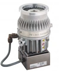 Another frustratingly close miss was in Dec 2015. A fellow from the USA mentioned on the eevblog electronics forum, that he'd picked up three turbo pumps discarded at his work. They were Agilent TV 301 Navigators (only one had a controller), with ISO 100 flange fittings. Manual here. 4.5MB
When I asked, he seemed agreeable to sell them to me. But then the problems... His company job is related to US tariff codes, which is not far removed from technology export controls. He doesn't know anything about vacuum systems. Perhaps because they are shiny it occured to him that these pumps might be export controlled. (They're not, the idea is ludicrous.) Anyway he looked up some regulations (would not tell me where), and misunderstood the units of the figures he found.
Here are his words:
"I was looking at the vacuum pump specific area, and our internal questionnaire. The flow rate at atmosphere before it is controlled was 5 m^3/h if I recall correctly. These things are 250 l/s so that comes to 15 cubic meters/h."
Sigh. Anyone who knows about vacuum pumps will immediately spot his conceptual mistake. And a separate basic maths error.
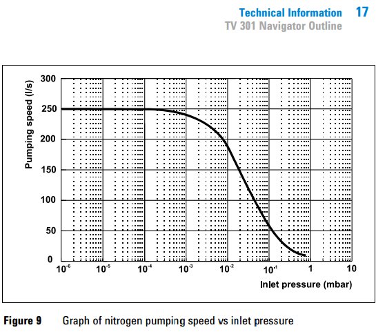
These things are NOT fans. The inlet may look like the inlet of a jet engine, but there is no similarity of function. Go read the Wiki article. They don't pump at all unless operated in an already very good vacuum. The chart at right is from the manual. Note that a Bar is a unit of pressure that is about equal to one standard atmosphere pressure. So a milli-bar (mbar) is about one thousandth of standard atmosphere. (Exactly: 1 atm = 1013.25 mbar.)
So where the graph says the TV-301 can pump "250 liters/sec" it means below around 10-3 mbar. Which is 10-6 of one atmosphere. It's talking about how much volume of extremely good vacuum (not many molecules in it) it can move.
His quoted 'controlled export' limit is 5 cubic meters per hour at atmosphere. That's an enormous vacuum pump!
Anyway let's convert 250 l/s at 10-6 atm, to cubic meters per hour at atmosphere (ie 1 atm.)
There are 1000 liters per cubic meter. And 60 × 60 = 3600 seconds in an hour.
So it's ( 250e-6 × 3600 ) / 1000 = 0.0009 cubic meters per hour. Not even a single liter.
That's what this pump can pump if all the throughput was accumulated at atmosphere.
But in fact it can't pump like that by itself anyway, without a backing pump.
Attempts to explain this to him failed. He insisted the two numbers had to be directly compared. Except he multiplied 250 l/s @ 10-6 Bar × 60 (wrong, should be "× 60 × 60" ie 3600) then divided by 1000, giving 15 cubic meters per hour. He thought. Except that's still a volume at vacuum pressure. Never heard of Boyle's Law? He couldn't understand the need to work out the volume when compressed to atmospheric pressure. Since the export control limit he quoted states "at atmosphere." So painful.
I'd kind of sat back, trying to think how to approach the discussion next, when he started talking about how he removed the top cap and spun the rotor (touching it with his bare fingers) and then saying he wanted to try powering one up with the controller and watching it spin. In room air.
For those who don't know, both of those are extreme no-no's. Skin contact leaves oily residue, that under vacuum continuously evaporates volatiles and severely impacts the ultimate vacuum reachable. One fingerprint inside high-vacuum gear necessitates a tedious tear-down and multi-phase cleaning effort. As for blowing room-air dust through the pump internals ... just arrrrgh.
 Not to mention that this pump's operating speed is 56000 rpm, and the blades are not rated to do that in air. Letting air into a vacuum system while a turbo pump is running will result in a blade crash.
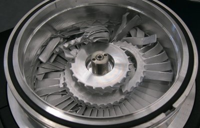
Turbomolecular pump 'blade crashes' are extremely destructive, typically destroying the entire blade stack. Like this →
Note that a lot of pieces are missing, because they probably flew out like shrapnel. At very high velocity. This is why turbo pumps always have heavy thick walls of high strength steel. Personal protection.
When he started talking about touching the rotor, and running them in air, then didn't seem to be listening when I politely told him why that was a bad idea, I stopped communicating with him. If I continued I'd have said something rude.
And so that was that. Not just a failure, but painfully frustrating.

Roadtrip Precedent
Back in Feb 2012 a friend had put me in contact with someone he knew in Ballarat, Vic, whose company was about to throw out a HP 3567A FFT Signal Analyzer, with manuals, software, etc. Did I want it?Ha ha, yes! I contacted him just in time, he'd already thrown the manuals in the dumpster, but dug them out again for me.
I wanted it enough to arrange a road trip from Sydney to Ballarat (970Km each way) to fetch it. (+ camp detours, say 1000Km.)
 |
 |
 |
 |
 |
 |
Well, not just for the 3567A. A few other things too.
1. Visiting the Eureka Stockade memorial. Where Australia almost began a revolution against the British Colonial authorities, but failed. By bad luck in timing, of just a few hours. If the column of armed miners on their way there had arrived half a day earlier, Australian history would have been very different.
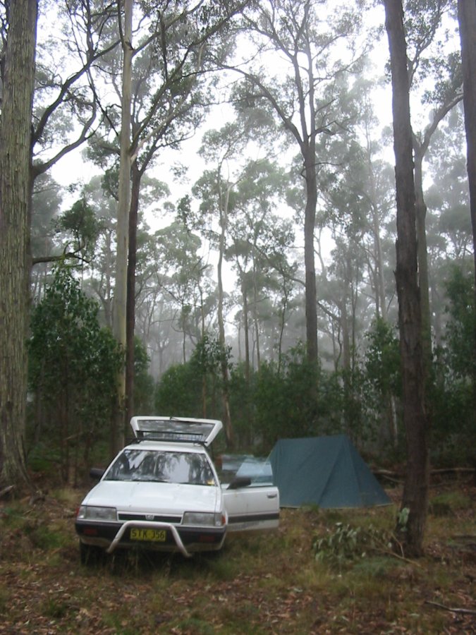
2. Morning mist camping in the Ballarat gold fields, for a week of fossicking.
3. A small party of friends in Melbourne. Something something 2012 Clan eze...
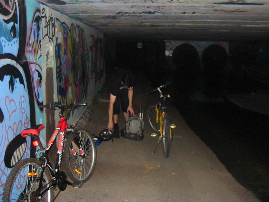
4. Subterranean bicycle touring. Seeing the city from the underside.
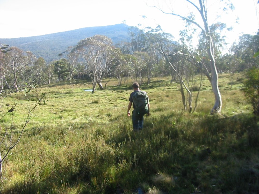
5. Atop Mt Cobberas in the Australian Alps. (Summertime, no snow.)
6. And the next day, nearby Ramshead Range. To lay the last of my father's ashes in his favourite walking place. He'd once referred to the glades of the range top as the Elysian Fields. And it is very beautiful.
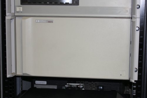 For all that, the 3567A has the plainest front panel of any instrument I own.
The funniest part was that when he'd thrown the manuals in the dumpster, he'd decided to keep the ring binders. So threw the pages in loose! I got them as a stack of semi-random order pages, and the empty binders. I didn't want to leave them like that, not knowing if major bits were missing. So right after picking the system up from his work I drove to a nearby public park to sort them out. But it was a very windy day so they had to be sorted inside my car. A pity it didn't occur to me to take a photo, because it looked pretty comical.
All the pages were present. Except the entire Installation Manual, that had apparently been lost previously. I bought one on ebay.
Random Meeting
Back to the turbo pump hunt. In early Oct 2016 I'd had a new acquaintance round to look at my workshop, and discuss our technical interests. We'd met through a group of mutual friends. Checking emails now I notice that the day we met was my birthday, but I don't recall noticing that on the day. It was a fun chat, and we got so distracted we nearly left (to drive him to the airport) too late to catch his flight back to Melbourne. He made it to the checkin desk seconds after they closed, and they opened again for him. Phew.He's doing a Phd at Monash Uni in Melbourne. I'd mentioned my vacuum system project, its aims, and how I was held up for lack of some equipment. Like me, he enjoys dumpster diving. Turns out his Melbourne area has a lot higher grade dumpsters than any place I know in Sydney. Within a couple of months, his lab co-workers were complaining about the pile of stuff he'd been accumulating in a corner of the lab, for me.
Amazingly, he'd already found three turbomolecular pumps. Two of them with controllers, though one controller was marked as faulty. Lots of vacuum plumbing and other stuff as well. Too much (and some too delicate) to be feasible to pack and ship to Sydney. He'd planned to fly up to Sydney for a week again in early 2017, so we figured the best thing to do was for me to drive down there, pick up him and the gear, drive back to Sydney. Looking at schedules, we could also go to a friends-group party (in a cave in the Blue Mountains) on the night we returned to Sydney, then go on out to Kanangra Walls via Jenolan. I wanted to show him the scenery there. He could stay at my place the remainder of the week holiday he had, then fly back. (This time avoiding nearly missing the flight.)
So, another roadtrip for gear. Only this time more driving, less relaxing. On the Ballarat trip in 2012 I'd done the trip down in two stages, camping in a state forrest Sth of Gundagai. This time I planned to do the same, leaving Sydney on the 18th Jan 2017, and arriving at my friend's place on the 19th.
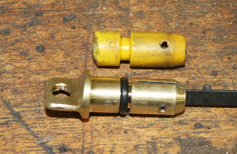
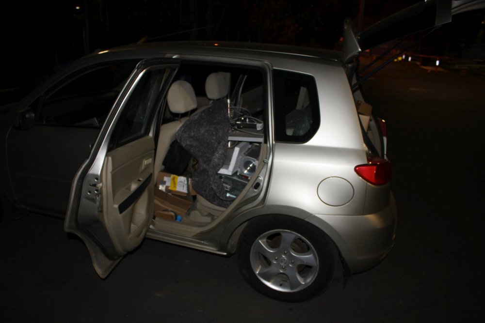
But first, some preparations. My old Subaru was a bit suspect for a long drive atm, so I'd be taking a different car. That one needed a service (done, new exhaust oxygen sensor and some other minor things, several hundred dollars, ouch.) Also there's another small but annoying flaw — the plastic handle on the oil dipstick is broken off.
 |
 |
 |
 |
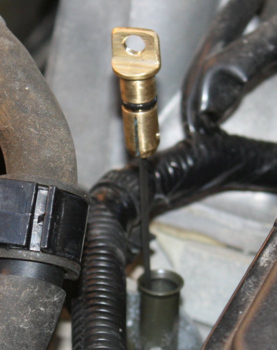
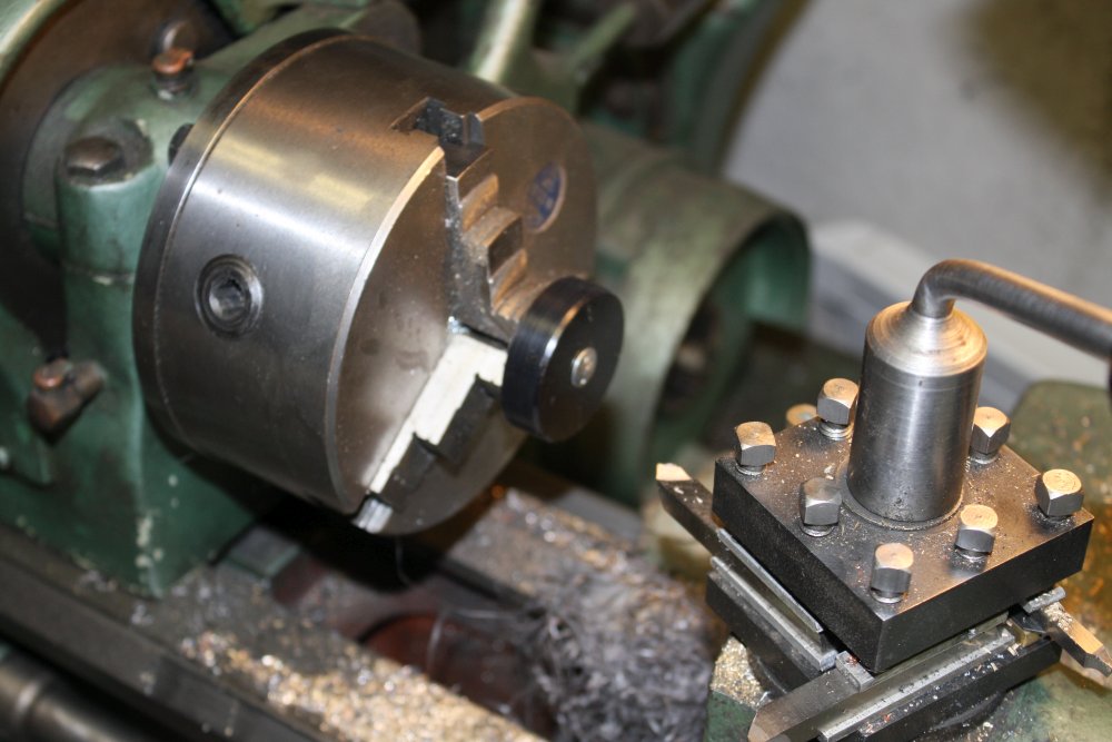
1, 2. Making a new dipstick handle, in brass. That won't break again. Trivial to make.
Well I would buy a lifetime supply, if...
A not so trivial problem. I should do an article on simple necessities of life, that are becoming increasingly difficult or even impossible to find, if you have any kind of standards of 'sensible, functional products' at all. It's a growing list.One of the most critical items would be comfortable, functional running/hiking shoes. For most of my life I've been sticking to the best ones I've found. They went through a few name changes, but the design stayed much the same. They are very light, robust, and have a flexible sole with great grip on all surfaces. With mesh uppers they dry out fast, so walking through a river only means briefly wet feet, and they never feel sweaty.
Sadly though, a few years ago they seemed to have stopped being made. Every sports shoe store I asked at said yes, they remember them, no they don't have them any more. And I couldn't find anything even remotely as good. The whole running shoes market appears to have gone nuts, with the stupidest, over-priced, ridiculously over-styled and too heavy, too rigid rubbish.
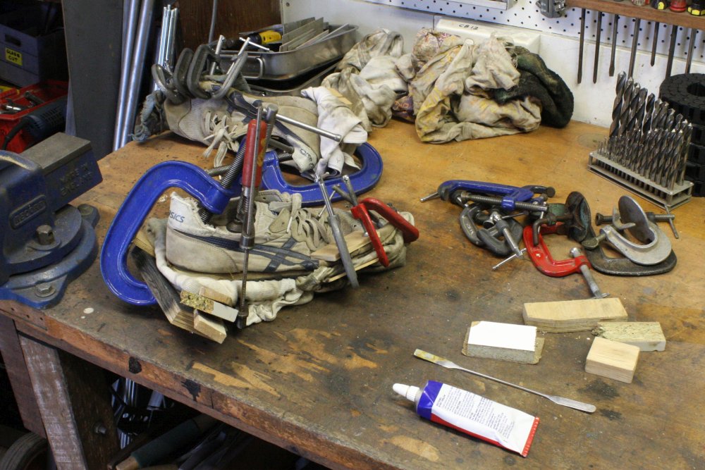
But I was down to a last pair of my old ones, and they were in the final stages of worn out. Also the soles are separating in some places. I had some nice looking recently-new shoes for the trip, but dammit they are just not comfortable. I don't want to drive literally for days, in those.
As an emergency measure for this trip I re-glued the soles on my old shoes. (Pic 3 above.)
But also, I made another attempt to find out what happened to my favorite type, and whether there was any chance of finding more. One of the places I'd tried a few months ago (shoe sellers at Paddy's market, at Flemington on Sundays) had mentioned that Asics have their main NSW warehouse out at Eastern Creek (10 Interchange Drive), and they have a small store there selling "run-out ranges" at discount.
Rather than phone and try to describe the shoes I wanted (surely a useless effort), I drove out there wearing my old ones. It was an extremely hot day and it's a long drive. In the store I first browsed the displays. Good grief, sports shoes have become even more insane since the last time I looked. Now they are not only 'styled' far beyond functionality, but they are also all rainbow mashes of bright fluorescent colours. Like I'd want to wear neon lights on my feet, not. Also they are dishonst — most of them have the word "gell" somewhere in the on-shoe slogans, and features around the edge of the sole that pretend to be evidence of internal gell-pads. But when you press around on the inner sole with your fingers, there's no trace whatsoever of any gell inserts. It's all just standard foam rubber. Which is good in my opinion - who'd want to go bushwalking in shoes that could get a puncture and go flat?
Ha ha, I asked one shop assistant about that, and his reaction was comical. He couldn't conceive that Asics might actually lie, and that in fact there might really be no 'gell inserts' in some shoes that claimed to have them. I must remember to grab any discarded gell-sole shoes I find in future, and dissect them. Curiosity.
Next I tried asking the shop assistants. "Hi, do you remember these?" (Pointing at my old shoes.) "Are they still made?"
The first three I asked all vaguely remembered them, but thought no, they are no longer made. Just as I was leaving (feeling quite depressed about the long hot drive for nothing, resigning myself to probably never having these familiar and nice shoes again, and the state of the world in general) I asked another shop assistant near the door.
Ah ha! He thinks they are still made. We go to the main desk with a PC linked to the company internal stock lists. He finds them! With picture; they are definitely the right ones, and a name - Asics Tiger Touch.
And here's where it gets weird.
They are supposedly only sold through a single store in Sydney - the Asics flagship store in Queen Victoria Building, Sydney city center. What? Why? He doesn't have an answer. Checks stock there - they don't have any in my size. One suitable pair is on order, but 'in transit.' I'm leaving for Melbourne the day after tomorrow, won't have time to go to the city, and can't rely on them arriving there anyway.
He does some more searching in the company database. Finds two more in the warehouse (adjoining part of the same building) but they are earmarked for another store. Uh... but you said they are only sold at one... No explanation. I ask if perhaps I could buy those ones right now. Just go and get them from the warehouse. He says no, that's not possible. After a bit more discussion, mentioning my trip, tight schedule, etc, he says he can email Asics management and ask. Will phone me tomorrow morning to tell me the verdict.
The next day, by nearly midday I give up waiting and phone him. Good news! He's been given permission to sell them to me. And is now waiting for the shoes to arrive from the warehouse. Supposedly they will be there by about 3pm. (Several hours, I suppose for someone to be allocated to dig them out of a pallet-load then carry them a few meters to the store.) So a bit later I drive out there again. It's even hotter today than yesterday.
As you can see, I got them. (Pic 4.) Never mind all the rigmarole, I'm really happy. Two pairs, $80 each plus two long hot drives, but it was worth it. I have comfortable shoes for the next few years. Also now I know the number I can buy them online directly, and according to the salesguy these are something Asics calls a 'core product line' and will always be made. I don't want to know why a 'core product line' isn't advertised or even sold in most stores. I just accept that many things in the commercial world are insane, and try to live with it.
Oh, and the fact that on the store stock screen the wholesale price is $40 and the RRP (which I paid) is $80? I'm not even going to get annoyed at that. 100% markup is pretty standard commercial practice. But it does mean I couldn't easily buy a lifetime supply.
To Melbourne!
20170118 - 20170120On the 18th I made a good early start. Looking like it's going to be a nice sunny day. I'd minimized the amount of stuff in the car, since it's a small car and there's a lot of stuff to be bringing back, plus my friend and his gear for a week in Sydney. No time for sightseeing either. No coast route, or Snowy. Just straight down the Hume.
 |
 |
Back in 2012 the Murrumbidgee River at Gundagai had been in flood. Here's a comparison with it in 2017. Too bad I couldn't remember where I'd stood for the first photo.
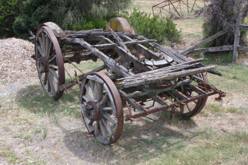 My hardy old 1994 Subaru was one of the last pre-computer models, and that's a major reason I hang on to it. You may think it funny that I'm a retired electronics and embedded computer systems engineer, and yet I refuse to own a vehicle with an embedded engine management computer. That's an involved topic, not for this story.
Instead, here's an old cart in Gundagai that makes me feel much better about the few age-related problems my car has. And my own too.
Meanwhile this was nearly half way already and it wasn't even 11am yet. The drive was going well; not much of the medical issue that can make long drives quite painful for me. Instead of the planned overnight camp I could just keep driving and reach Melbourne around 4 or 5pm.
 Phoned my friend, checked that was OK. Then drove.
And made the mistake of not stopping somewhere outside Melbourne to work out an optimal route through Melbourne to his suburb Murrumbeena, SE of the city.
Oops.
Once I'd entered city traffic, there wasn't much opportunity for planning. I was using a paper street directory, so just took what seemed the direct route. Off the end of the M31 and onto Sydney Rd (ironic), then King St.
Where it becomes sadly apparent that Melbourne too has homeless people.
 And then... stopped. Stuck in 5pm central city motionless traffic jam, yay.
Sigh, I really walked into that one. And wish I was walking, it would be faster.
Still, sitting stuck in a traffic jam is one way to absorb the nuances of a different city. It wasn't boring.
Exactly an hour later I made it to my friend's place.
That evening I got a tour of his retro-computing collection (mostly at another house.) Much younger than me and he's well on the way to exceeding my own volume of old junk that isn't likely to ever work again. Not sure if I'm jealous or alarmed.
The next day, the 19th, being in Melbourne unexpectedly I had a day to kill. No Urbex this time, I wanted straight up unadulterated tourist scenery. The plan was to go do the Dandenong Mountains, and then zip down to Fort Nepean on the Mornington Peninsula. Neither of which I'd been anywhere near before.
The Dandenongs were a surprise. I'd had the impression it was a major mountain range. Actually, it's a smallish hilly area, with a very nice almost rainforesty urban mix. The main road through that has the highest density of antique shops per kilometer I've ever seen.
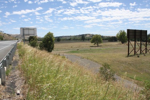
 Atop 'Mount' Dandenong itself there's a convention center and lookout over the plains of Melbourne. With a ridiculous vehicle entry fee to the hill-top area, so I just parked down the main road a little way and walked in via the forest to the East. More pleasant way to get there anyway.
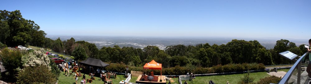
Here's the splendid view of distant Melbourne city center, from the lookout that everyone pays to reach.
Oh I'm sorry, perhaps that's not clear. Here's a larger view.
Better? No? You're still complaining? What do you mean you can't see it?
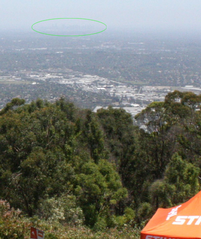 Now do you see it? Oh come on, it's a huge city.
Just a bit far away. In haze. Really.
Anyway, the important point is that 'Melbourne' is all that flat plain, and more over the horizon. It's somewhat large, and very flat.
After the lookout I started driving South-ish, heading for the eastern peninsula of Port Phillip Bay. Rapidly coming to the realization that I'd grossly underestimated the scale. I had arranged to meet my friend at his place around 4pm, and clearly I wasn't going to get anywhere near my intended destination by then, let alone get back.
I gave up roughly half way there, and turned around. Made it back 'home' in time. We had important business to conduct. Mainly, to transfer all the collected vacuum equipment from his lab to my car, but also first a ceremonial serving of dumpster diving, Melbourne style.
This was intended to be just for fun, without any likely result since he expected that today all the dumpsters would have been recently cleared.
Which was mostly true. They had been. Except there was one junked object sitting by itself out in the weather, that he'd been walking and driving past for months, and never paid any attention to. 'Nondescript beige box' kind of thing.
 |
 |
Later, back at his lab, I packed all the delicate, bulky stuff into the car. With the aid of an almost unlimited supply of bubblewrap, styrofoam and cardboard sheets and boxes considerately provided by a row of recycling bins.
Fortunately it all fitted, despite the unexpected extra treasures from the 'nondescript beige box.' Actually the 'box' was a waist-high enclosed 19" equipment rack, and I'd have liked to pack that in too, but it totally wasn't possible. Had to make do with just the rack's contents.
A lot of this article later on is going to be about that very lucky sci-treasure find. Patience.
Melbourne-Sydney-Katoomba-Party-Jenolan-Kanangra
20170120Next day (Friday) we set out at 6am for Sydney. Quite early because we had a 7pm party in Sydney's Blue Mountains to get to. Google claims Melbourne to Sydney via the Hume (M31) is 856 km, taking 8h 26min. That time is very optimistic, even though much of the highway is zoned 110Km/hr. Originally the plan was to share driving, but when checking car insurance details (not my car) it turned out my friend wouldn't be covered. So, another all day driving for me. Third in a row.
 We reached Sydney around 5pm. Quickly unloaded the car, loaded camping gear in my Subaru, left for Blue mountains. Got to the party around 8:30pm (after a little bit of wandering in the bush in the dark, not sure where the cave was.) Stayed till around 1am. Drove to Kanangra, camped at the Unirover Trail campsite around 3am.
I had my camera the whole time but forgot to take photos of the cave or campsite. Maybe a bit tired.
Someone else's daytime pic at left.
The road to Kanangra goes right through the main limestone cavern at Jenolan. By that time it was very late, but since my friend had never seen it, we stopped to gawk. Wandering around in the Jenolan Caves Grand Arch at 2am, all lit up but totally deserted and silent, is a strange experience.
Kanangra Walls
20170121
 |
 |
 |
 |
 |
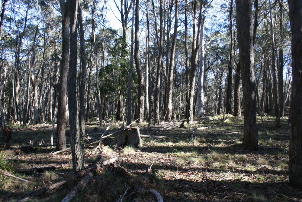
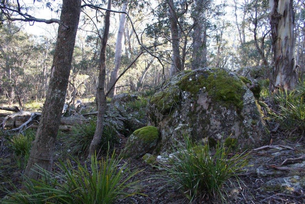
1,2. The campsite area, pics from a previous trip. It's open snowgum forest with tussock grass. Snows often here in winter. One of my favorite camp spots, and there's rarely anyone else here.
3. The main lookout at Kanangra Walls. Thank God the vandalous NPWS have (somehow) restrained themselves from ruining this with tourist safety barriers. I'll never forgive them for what they did at the nearby waterfall pool, and the track down to it. Whoever was responsible for that should be shot.
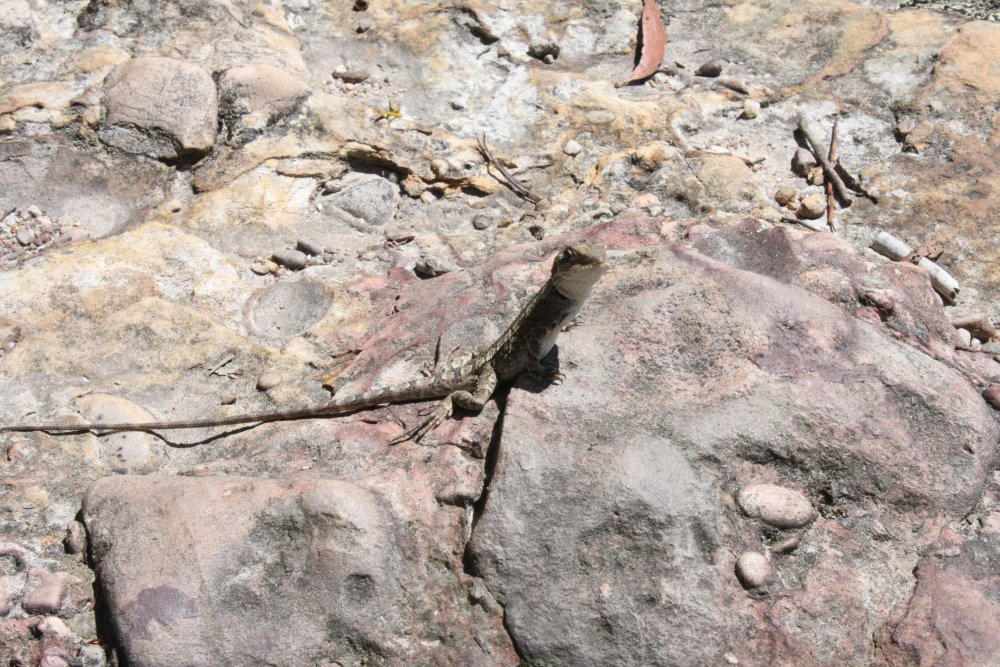
4. At the lookout, the lizards are very tame and inquisitive.
5. Looking Nth, to Mt Cloudmaker in the distance. For me, it's a day's walk from here to the plateau just to the right of Mt Cloudmaker. But we are not doing that today.
 |
 |
 |
 |
 |
1-5. Some more views. We walked out to the end of the main plateau, had lunch there. Panorama (click):
 |
 |
 |
On the way back to Sydney we made it to the Three Sisters lookout at Katoomba right on sundown. Second pic is looking the other way, to the Southwest. There goes the sun.
Back in Sydney my friend did the tourist thing for a couple of days, plus one 'Sydney from underneath' tour a friend and I put on, Fortress style, before flying back to Melbourne.
Dealing with it
20170122Ho ho ho, the Melbourne trip and a 'quick sorting out' of the gear on return were supposed to be only a couple of weeks sidetrack from something else I was in the middle of. The 3D printer, and an offshoot project from that. Not to mention a painfully long backlog of other projects. So much for planning. Because of course one can't just leave a pile of stuff like this sitting around in the workshop. It has to be dealt with properly. At least to stabilize it, so things don't get lost, damaged, etc.
 |
 |
 |
 |
 |
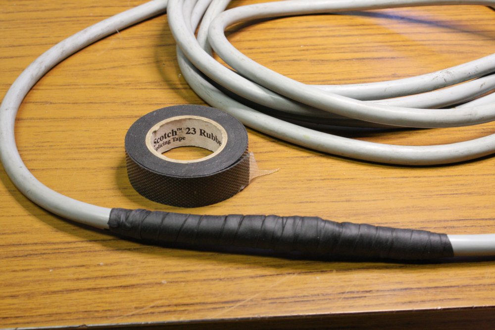 |
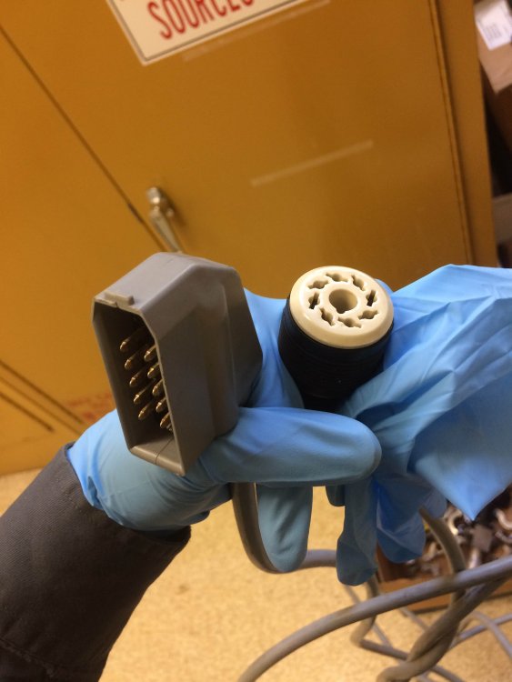
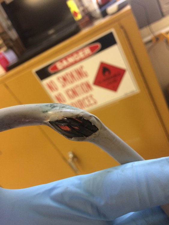
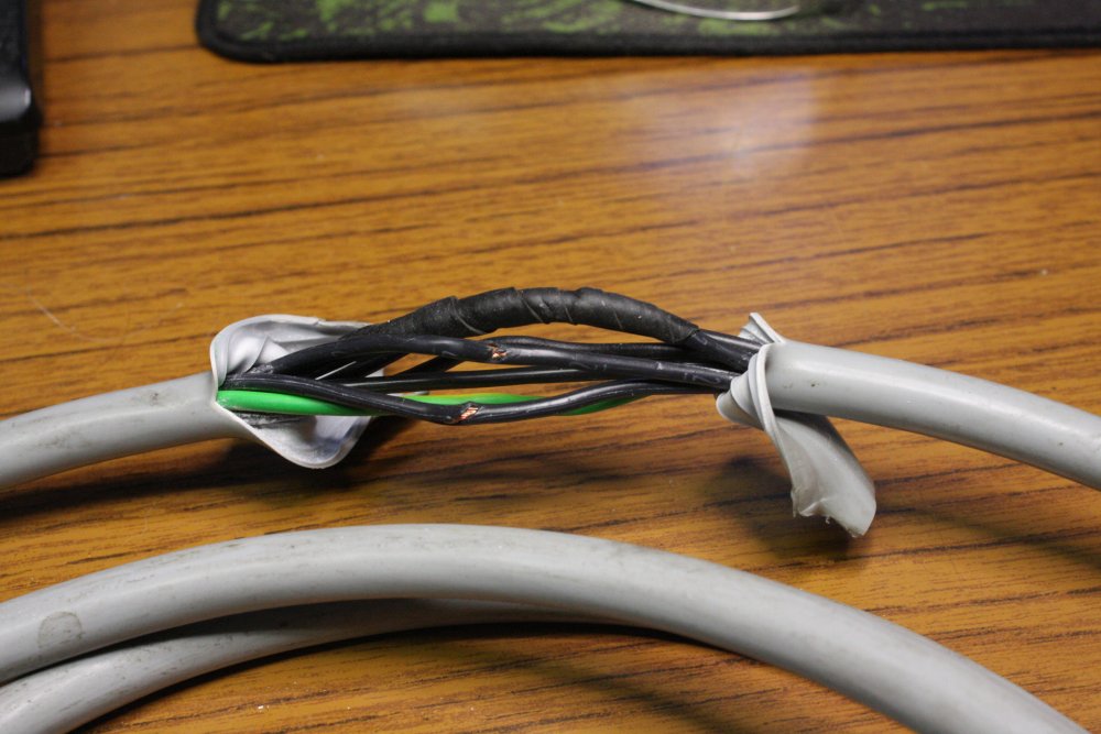
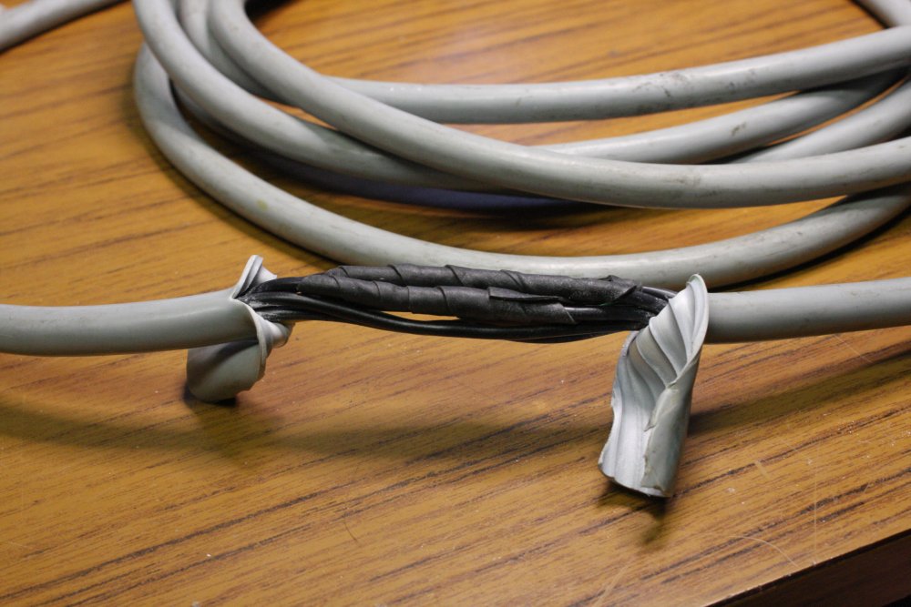
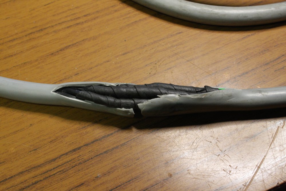
1-6. On the rest day after I got back home — fixing a cut cable. This goes between the Leybold TURBOVAC 360CSV turbo pump, and its controller. The machine they were in had been put in a dumpster, and the cable got squished under the metal frame. That black tape I used is a weatherproof rubber tape. While applying it you peel away the backing film, stretch the rubber out and wind tightly. That activates it, and it melds to itself forming a single rubber sheath.
Sorting the Expected
20170122 - 20170203The previous couple of months my friend had been sending me photos of stuff as he found it, so the Melbourne trip was to fetch a known amount of equipment. Mainly for the turbo pumps since they are both unobtainium, and too heavy and delicate to easily pack then entrust to a courier. Even given their unknown functionality they alone were worth the trip. The rest of it was a bonus.
And then... there were two other completely unexpected treasures. One of them the 'nondescript beige box' surprise we came across while doing a ceremonial hi-tech dumpster diving tour, the other was something discarded at my friend's work, that he knew of but hadn't bothered to photograph. He hadn't thought it was of much interest.
We'll get to those. But first here's the expected pile of vacuum equipment.
 |
 |
 |
 |
 |
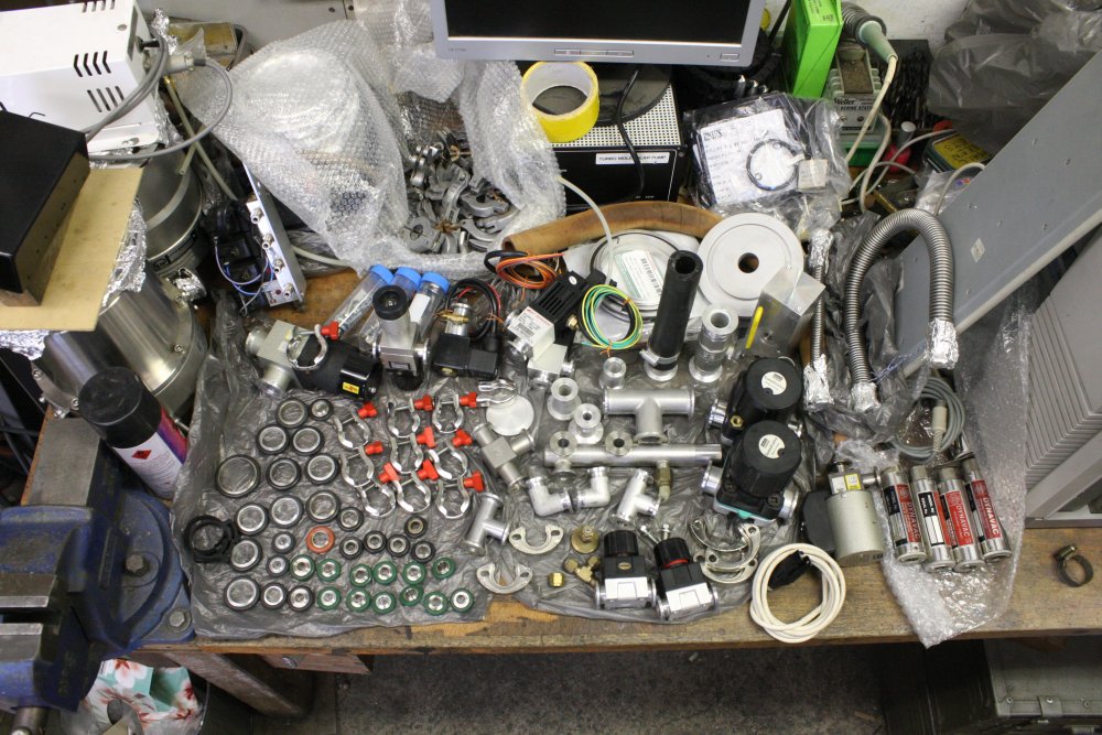
1. Some plumbing and valves. Mostly KF form.
2-5. Three turbomolecular pumps. All unknown condition:
- LEYBOLD LH TURBOVAC 360CSV. With an apparently working controller and cut cable. That I'd fixed.
- EDWARDS EXT250H. Has a controller, marked dead. Edwards are one of those companies that will not release schematics. Well, we'll see how this works out.
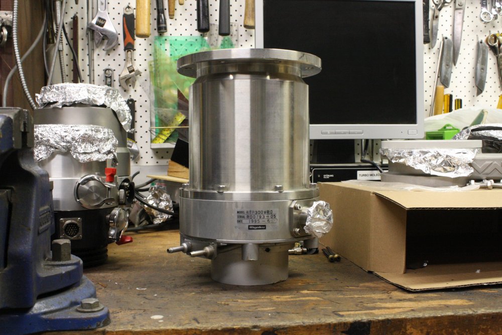
- RIGAKU RTP 300 VRC. No controller.
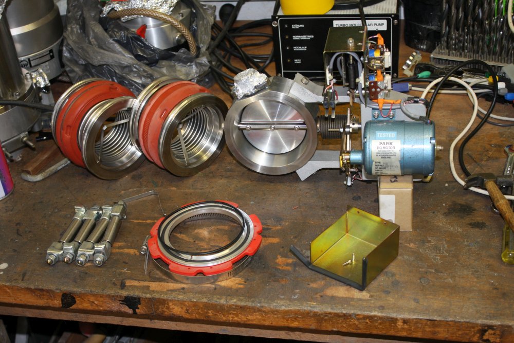 |
 |
 |
 |
 |
1. A large electrically actuated butterfly valve, with two stainless concertina bellows.
2. A very cute Edwards B62424210 oil diffusion pump, with integral pneumatic butterfly valve. Oh man, I wish that butterfly valve was removable. It's very fast-acting and would be perfect for a part of the intended system. But sadly it's welded to the pump body. I may yet consider cutting it free, but that's not to be done lightly.
3. A fine Leybold H. gate valve. Very clean but unfortunately only manually actuated. Not sure if I can automate it, due to the amount of force it requires to close/open it near the end of travel.
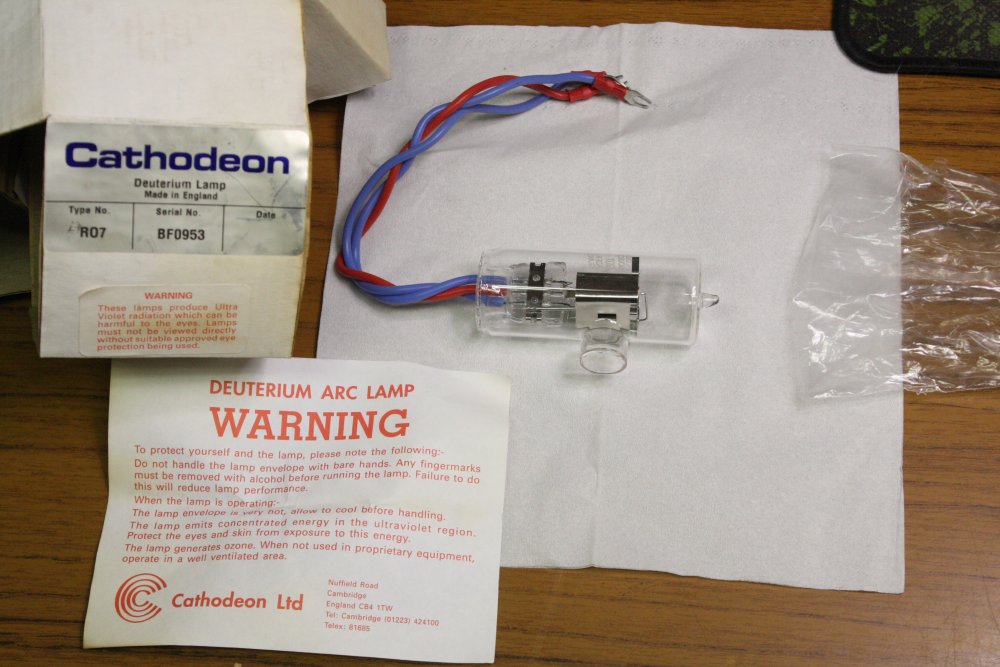
4. A Cathodeon R07 Deuterium Lamp. Old but little used (according to a note on the box.) These are UV light sources for spectroscopy. So far I can't find technical data, such as what electrical drive it requires. For me it's more of a tech-museum piece anyway.
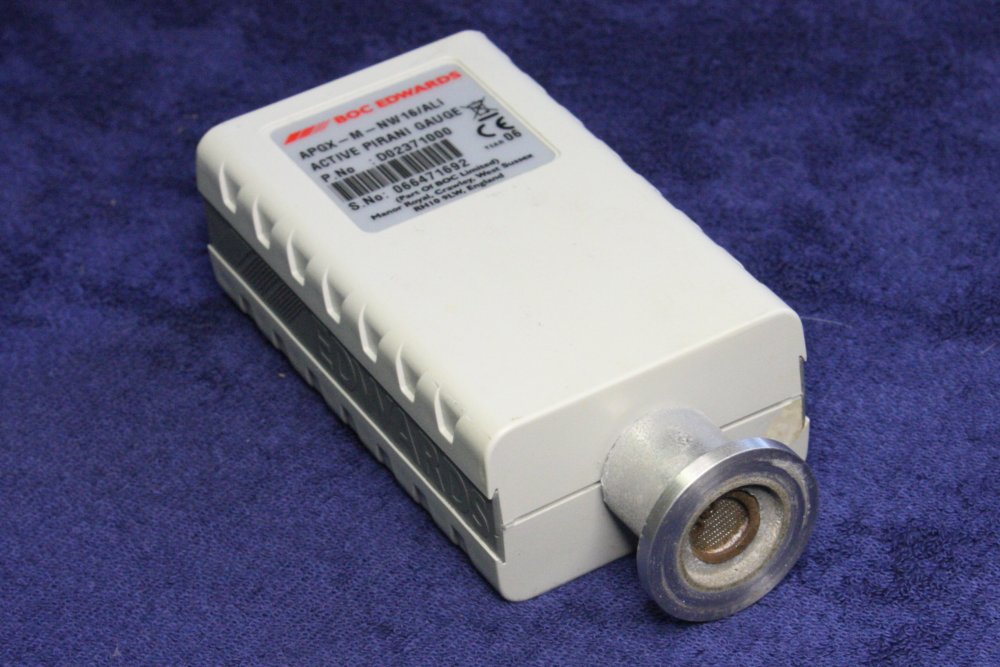
5. An Edwards APGX-M-NW16/ALI Active Pirani Gauge. It's a nice vacuum sensor, but obviously badly contaminated and corroded. Something to dissect for curiosity mainly, but perhaps repairable. Being Edwards, there won't be any service information available.
 |
 |
 |
Even if dead and unrepairable this will be interesting to take apart. But if working... cool. Adding 'laser cutting' to the combination 3D printer and router machine I want to make, will be that much easier.
 |
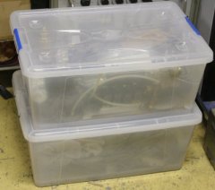 |
In the end, all the small stuff is packed away in these storage boxes.
Unbreaking buttons
20170126
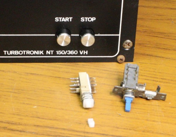 |
There'd been one small breakage in the car. The probably working turbo pump controller lost its front buttons. Worse, one of them had taken the shaft of the switch body with it. Darn. Since my friend wasn't too happy about me already breaking something he'd salvaged, I fixed this early on. Found an equivalent single-acting switch body, and swapped it in.
The controller front panel LEDs do a flash cycle that the manual says means the unit passes its self-tests.
Ideally...
For a rig intended for general purpose high vacuum pottering(†), there's a short list of things that would be nice to have. But which tend to be unobtainium for shoestring efforts.
- Turbomolecular pump(s). Definitely the best way for the hobbyist to reach high vacuum. If you disregard the cost, and the ease of accidentally destroying them, and red tape guys who fixate on how they must be restricted exports (they're not), and the numerous ebay sellers who don't understand about keeping pumps and controllers together... sigh.
- Helium leak detector. This uses a gas mass spectrometer tuned to Helium, for detecting gas leaks in a vacuum system. Small leaks can be quite hard to find otherwise. For glassware vacuum systems a handheld tesla coil can be used, and I have a couple of those. But my setup will have little or no glass sections.
- Gas Mass Spectrometer, aka Residual Gas Analyzer (RGA). When (for whatever reason) you need to know what kinds of atoms and molecules are bouncing around in the test chamber vacuum. There's just about no other way to know. And for the main objective of my pottering(†), I do need to know.
Btw, 'bouncing around' is not a figure of speech. In high vacuum the 'mean free path' of gas atoms is longer than the chamber size, ie they very rarely impact each other but instead literally ricochet around off the chamber walls.
My Helium Leak Detector
This project has been in planning for many years. Before I even had a workshop in which to attempt it, I had an opportunity to buy a Helium Leak detector, at the Cochlea liquidation auction. (Australian manufacturer of pacemakers and hearing aid implants.) So I have this Varian 936-60 SP. It came with all the service and operating manuals, instructional videos, and even a box of spare inonisation gauge heads and filaments for the mass spectrometer.It's been in storage for over a decade now, awaiting main project progress, and although bought as 'working', by now it needs an overhaul. Some pneumatic hoses have decayed, and no doubt various rubber seals and perhaps electronics will be kaput. But it should be repairable without too much trouble. The main plumbing section is still under vacuum.
The plan was to try modifying that to be a more general purpose gas mass spectrometer. Because accurate, versatile, working residual gas analyzers (RGAs) are just about the ultimate definition of unobtainium. I couldn't imagine any other way I was going to achieve that capability.
That's not an exhaustive list; I can think of plenty of other 'nice things' (for example a vapor-phase cleaning system) but these can be worked on and some of them I have, some I think I can improvise. No showstoppers.
Now with three turbomolecular pumps in hand (and a good chance at least one can be got working), this project can have another push. Meaning it gets back on the list of stuff to actively work on.
† Actually, I have some specific targets in mind, but those are pretty flexible and will adapt to developments.
Bonus Treasure
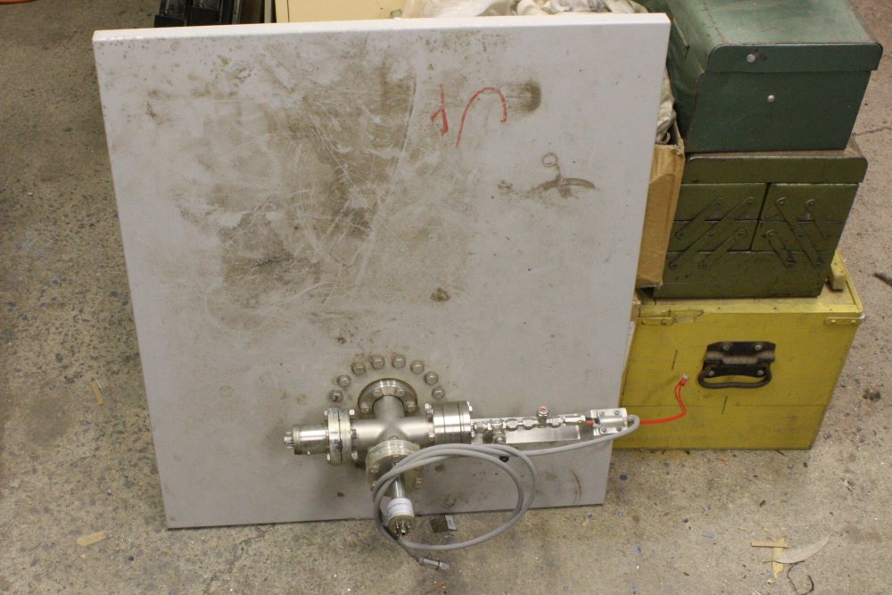
Research grade high vacuum gear has some striking common visual characteristics. Check ebay for 'high vacuum chamber' and you'll see what I mean.Apart from the heart attack prices, it's always shiny stainless steel, and has lots of bolts tightly spaced around flanges. (Due to the standard joint sealing scheme, in which a copper washer is squashed between two heavy flanges by great force, achieving a gas-tight metal-to-metal seal that can be baked at high temperature to boil off surface-adhering gas molecules.)
So, that afternoon in Melbourne we were driving around between dumpsters, when I noticed a thing sitting by itself half underneath a big rusted old hopper construction. It was a waist high beige box, with an old, small glass CRT monitor sitting on top, obviously having been out in the weather a long time, by the dirt and faded plastic. Nothing eye-catching there, except there was also something sticking out of the top of the box, that said 'high vaccum gear' to me. I asked my friend what it was, as we drove past. He replied he didn't know, had never bothered to look at it. And it's been there as long as he can remember. I nearly kept going.
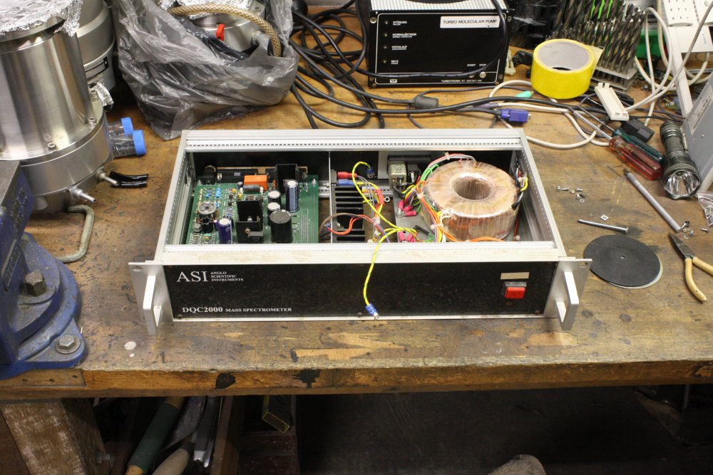
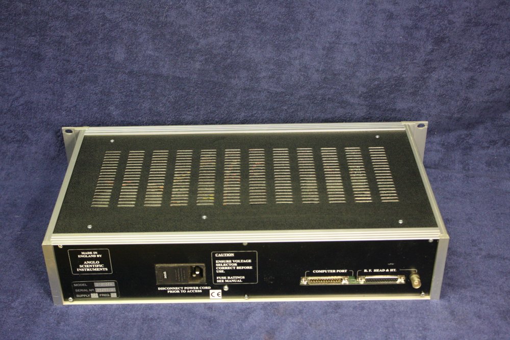
But didn't. Parked nearby, walked back to look. From the other side the 'beige box' is actually a 19" rack cabinet, with stuff installed in the side facing away from the street (and rain.)
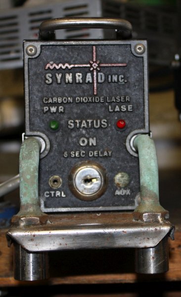
 The rackmount things are all equally nondescript - for example this plain aluminium panel (a bit corroded) with cheap switches and carelessly stuck on faded labels, plus a vacuum gauge readout module (aha!) Also a somewhat rusted squirrel-cage fan, some blanking panels dirty with long weather exposure, a very old looking PC on a slide-out tray, and one rackmounted thing with a black front, one power switch and some text. The large lettering didn't say anything meaningful, and I couldn't read the few smaller words as it was a bit dim here and I didn't have my glasses on yet. I'm farsighted, don't wear them when driving.
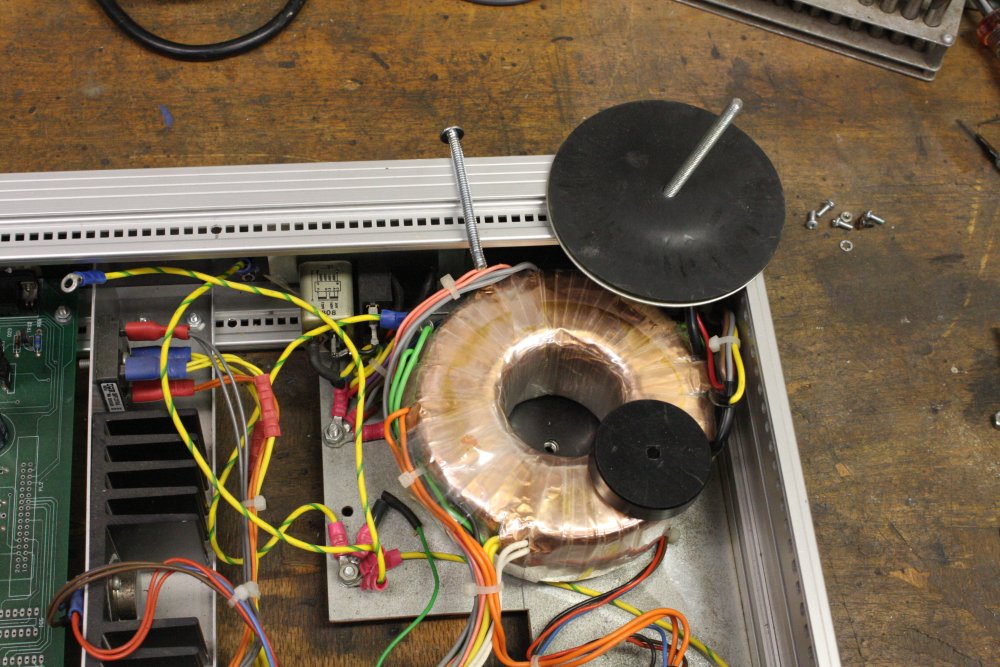
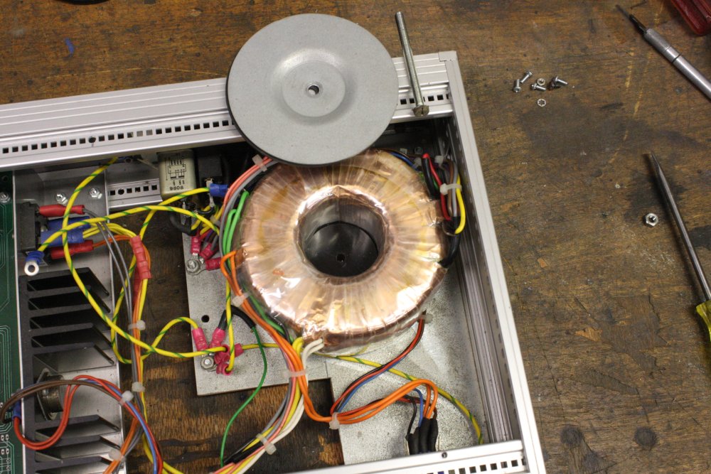
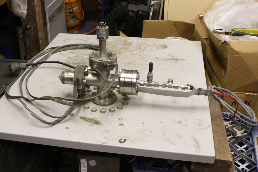
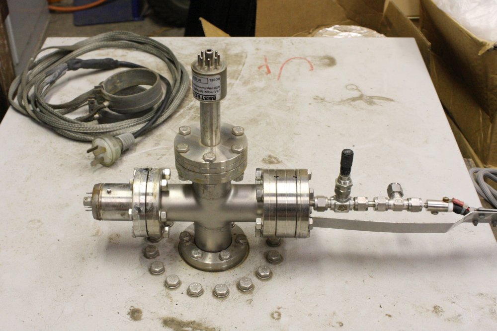
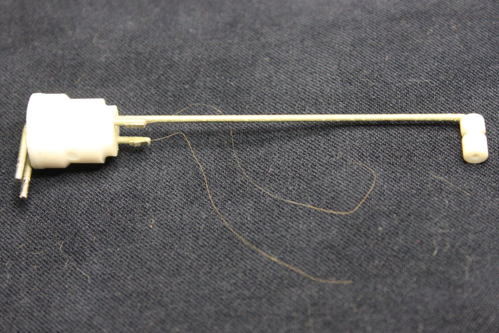
 The top panel of the rack unit (beige sheet in the pic at left) had this thing mounted in it.
It actually wasn't very impressive even without all the wires wrapped around it, due to being quite dirty and small. Just a stainless steel cross junction, with things attached to each arm. One of them a small black box. The base of the junction was mounted to the panel, with a large ring of closely spaced bolts.
I moved the old CRT monitor off the cabinet top to get a better look.
And put my glasses on.
Hmm, it's still not very informative. There's a nice vernier needle valve on one arm, but this has all been in the weather for so long, would it still be workable? What is this thing anyway? Some kind of gas inflow regulation on the needle valve side, a vacuum sensor on the upright arm, and the other arm has some kind of detector.
What does it do?
Measuring something about a low pressure gas?
I wonder if...
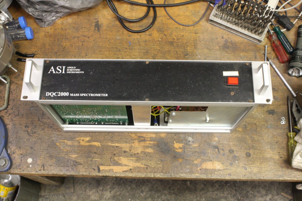
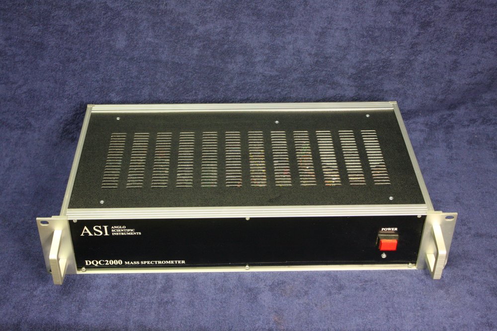
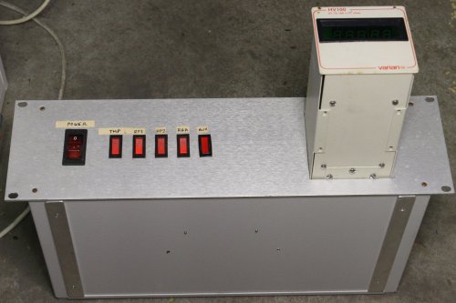
Then I looked at the rack front again, with glasses on.
Now I can read the smaller print.
Jaw drops...
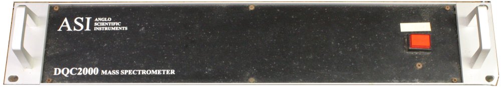
It's a gas mass spectrometer. An RGA. I don't believe it. Why is it sitting out here in a junkpile, exposed to the weather? But never mind, thank you very much Lady Luck. Again.
Presumably it was thrown out for a reason and doesn't work. But I know how this goes - often places like this just couldn't be bothered (or able) to fix minor problems. Or maybe their budget gave them a nice newer one. It's definitely worth taking this home for a careful evaluation.
Positive sign number one - right there in the rack is the PC that is obviously the system controller, and if it can be made to work it might still have the system software on it. Without which the hardware is useless. The fact that the old CRT monitor and a weathered looking standard keyboard were left with this system, suggests it was working (somewhat) at the time it was discarded. Also a quick cables check reveals there don't seem to be any missing things.
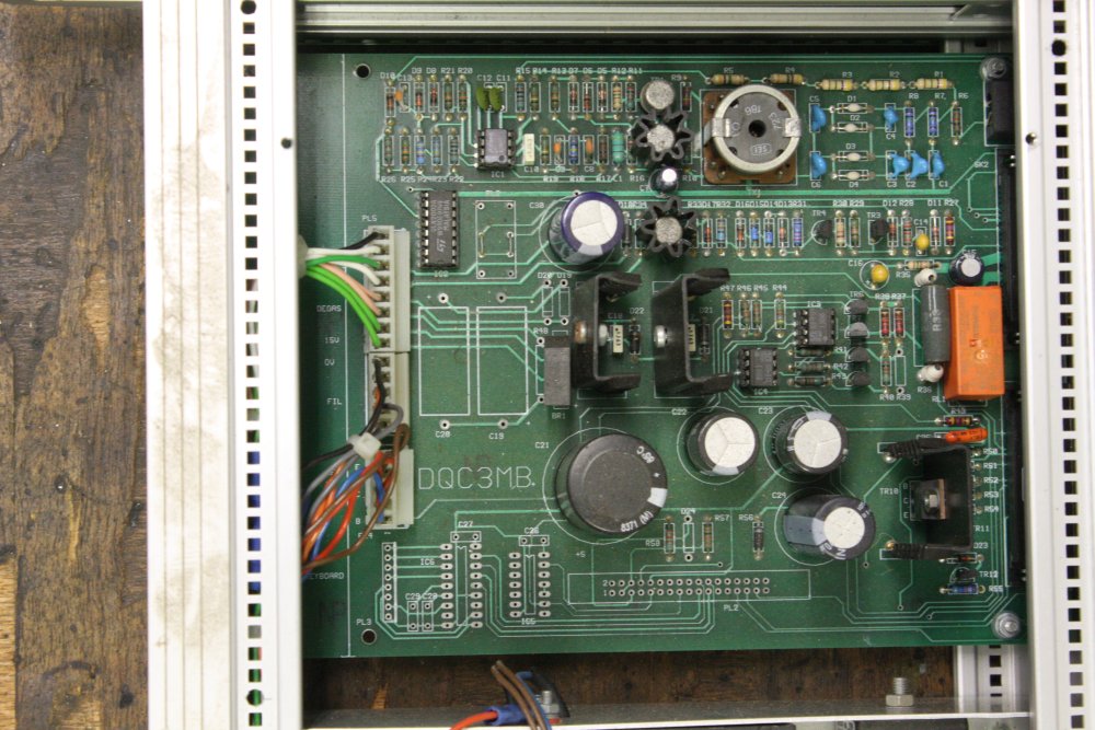
So that's all hopeful. The biggest issue is that it's been in the weather for a long time. Yes, that DQC2000 front panel above is black-painted steel, and that is rust spotting all over it. But, the vacuum section internals should be impervious. Everything in the rack has been relatively protected. Maybe all good...
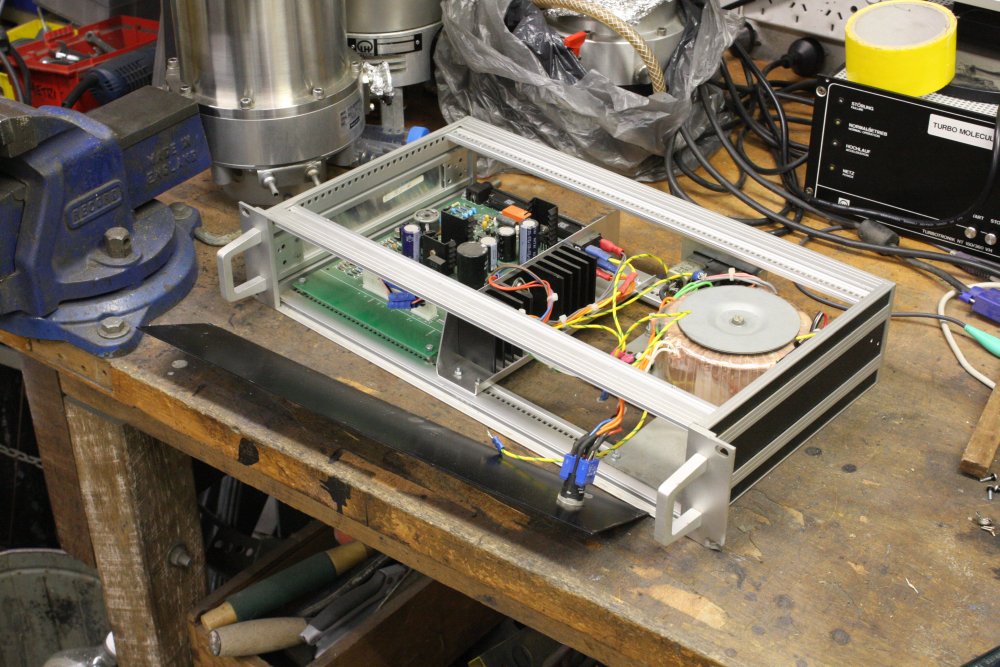
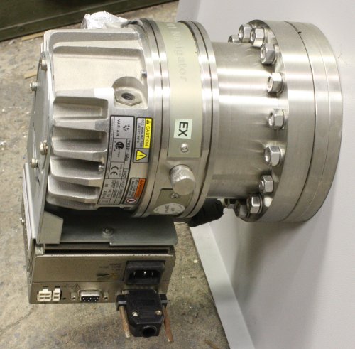 I'd opened the rack back access panel by now.
Hey, it has a turbomolecular pump! With the controller! Ha ha ha!
Someone had already taken the rotary backing pump and interconnecting plumbing, what a pity. But never mind, I can easily substitute for that. And... wait a minute. The turbo is labelled "Varian TV 301 Navigator". That sounds familiar... Those ones in the USA, those were Agilent TV 301 Navigators, I seemed to recall. What?
It turns out, Agilent bought out Varian, so they are in fact the exact same model as that guy in the USA convinced himself were 'too secret' or something and he couldn't ship them overseas. To Australia, a close US ally.
This is just a perfect, hilarious little extra cherry on top of an already delicious ice cream luck-desert. I can't stop chuckling every time I think of it.
Well that was a splendid surprise. At least some chance of adding an RGA to my experimental system, albeit with quite a lot of refurbishing work required, and no guarantee there isn't some showstopper fault.
Being rack-mount all the parts were easy to extract. That top panel was awkward to fit in the car, since it's not possible to remove the vacuum parts from the metal panel without breaking the main vacuum seal at the turbo. That is one of the CF (Conflat) types, so can't be undone and rejoined without a new copper gasket. So it remains a large, awkward, heavy object, with projecting delicate bits. But we managed to pack it in securely and safely.
Delayed Second Surprise
After a few more dumpster inspections (nothing much), we headed to his workplace to pick up the gear stockpile. In the process of which I was given a tour of some other parts of the building and outside.In particular to one spot where various bits of discarded junk were piled. More 'exposed to the weather' stuff. He pointed out a thing that looked very incomplete, and said it was mine if I wanted it.
 ← It didn't look very auspicious at first glance.
But it grew on me. Despite being apparently half missing it might be interesting. The front looks OK. ↓

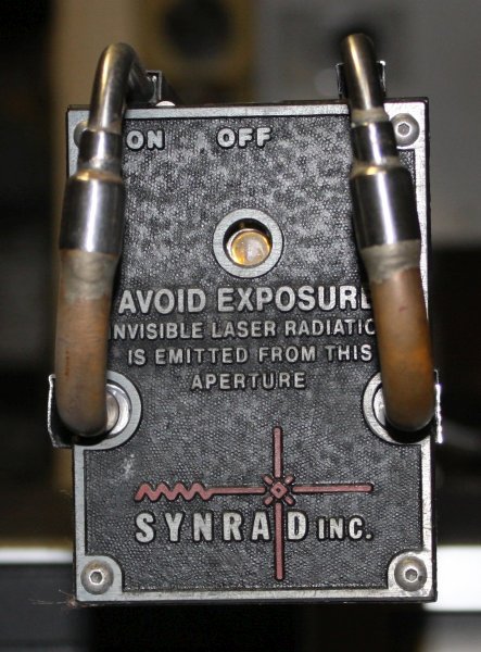
 Plus there's this: "HP 5973 Mass Selective Detector"? For what? Where's the input? That's clearly a vacuum chamber, so could it be...?
Not expecting much from such a 'partial wreck', I loaded it in the car anyway. Back home it landed on the misty end of the workbench. Where it sat forlorn while I was occupied elsewhere.
When I finally got to it, two weeks after returning... a second huge and wonderful surprise. Be patient, you'll see later. As for the incomplete-looking case, it's supposed to look like that, since it is meant to run in conjunction with a gas chromatography system that it sits up against. There are only a few things missing — a tiny oil diffusion pump and roughing pump, and a driver for that vacuum gauge head sticking out the end of the aluminium vacuum chamber.
Overall from the trip, FOUR turbomolecular pumps, and TWO gas mass spectrometers. Much more than I'd expected.
Resurrecting the RGA PC
20170125
After sorting out the small stuff, there's the larger, more important gear to be evaluated. Does the Leybold turbo pump and controller work? But the really burning questions all relate to the RGA, and most urgently of all, the old PC:
- Can the system software be recovered from the PC?
- Is there any web presence for this company and system?
- Is there any online information on the system?
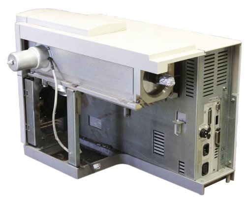
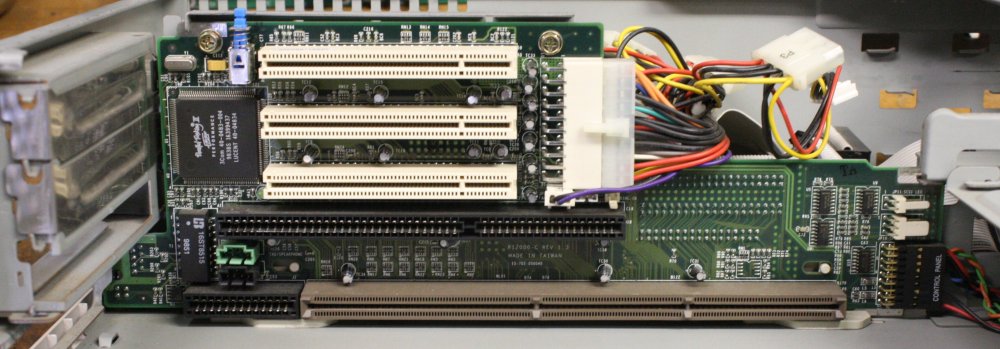
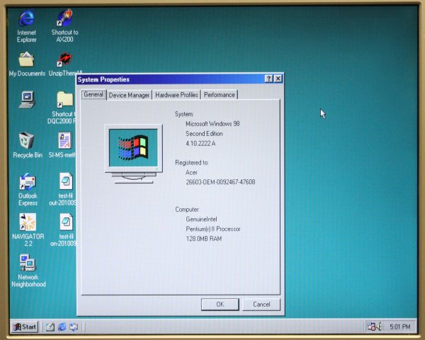
Those are photos of the control PC after disassembly, much cleaning, then reassembly.
Sticker on rear says:
Gateway 2000 Inc. Model No. E3200 AS PII-350 MAV SYS KER SN:00632861 mfg: 21/01/1999
The OS sticker: Microsoft Windows 98 Second Edition
Did you notice anything odd with the sticker wording? I didn't, initially.
Anyway, the machine was very dirty inside and out. The boards needed cleaning, the coin cell was completely flat, and the DRAM slot arrangement was whacky. Not to mention all the connectors that haven't been wiggled in a long time. Considering that the hard disk (hopefully) holds critical and irreplaceable files, I didn't want to try just powering up the machine.
So I pulled out the hard disk, to try reading it directly in an external dock on my PC.
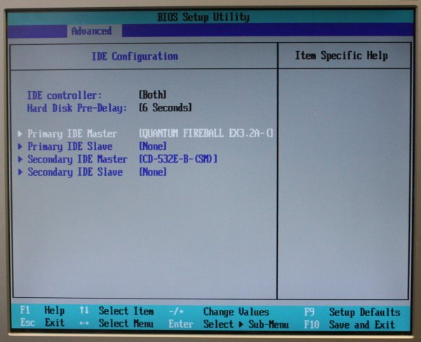
It's a HP Quantum Fireball EX 3.5" Series, 3.2GB AT disk drive. C/H/S 6256/16/63
An old style IDE drive, with low bandwidth IDE ribbon cables in the PC.
I have a hard disk USB external dock that takes IDE and SATA drives. It always works (except with some old drives that don't physically fit due to odd power supply connector position.)
Plugged in this drive, turned it on. The drive spins up, but does not appear in Device Management enumeration.
It does not even appear in ComputerManagement-->Storage-->DiskManagement as a non-formatted drive. According to the dock and my PC, it's just not there. I checked with another old, small HDD in the dock; it works fine.
Hmm. That's not good. The drive appears to be completely non-responsive. But strangely, I can hear the heads do their little startup dance, and it sounds normal. Dead drives don't normally do that.
Disappointed, thinking "Well so much for that. Not getting an RGA working without software" I gave up for the evening.
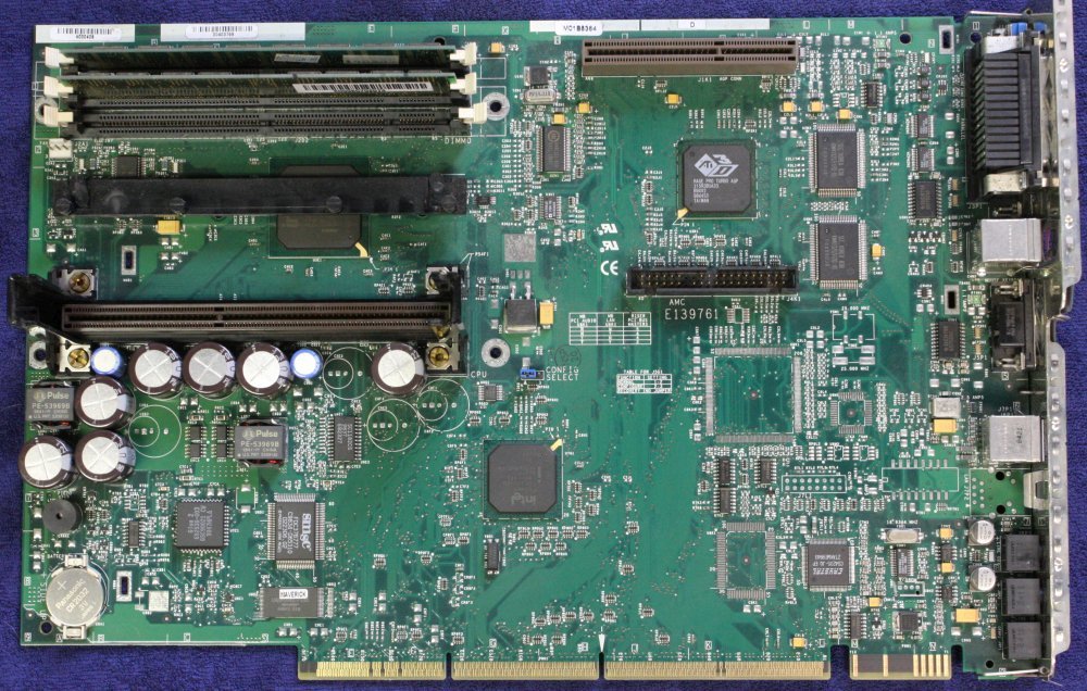 |
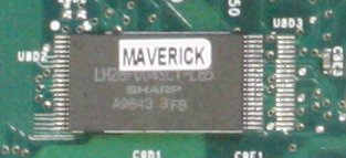 |
Next morning, while having a quick look at the odd format motherboard, I noticed something. On the BIOS flash chip (which is soldered in) there is not the usual sticker from one of the typical BIOS makers. Instead there is an improvised sticker with just the word "MAVERICK".
Ah ha! Recall that "MAV SYS KER" on the rear label?
I called it improvised, since someone used stickers that were too long, printed on them, then cut the excess off one end. Definitely not to be expected from a mass production operation.
Well, well, well. This suggests the BIOS is some quite obscure custom version. I get no relevant google hits for "MAV SYS KER" or 'maverick system kernel'. Presumably the word 'maverick' would have been chosen to indicate going against standards in some way. Supposing it's the disk drive low level config that they've done differently, just so the drive can't be read on other machines? This strikes me as the kind of thing a small company making high-tech equipment might have done, intending to minimize copying of their software. At least, it seems a likely reason for why a custom BIOS at all.
Hopefully NOT something that is required to enable access to the interface card, so it can only be used in this PC. That would suck. Because of the amount of reverse engineering it could take to defeat it.
Anyway, I guess I should at least try the 'dead' HDD in this PC.
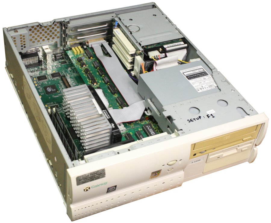
|
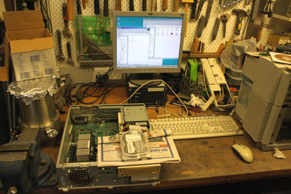
A couple of days later I finished cleaning and putting the machine back together.
Such a horrible, awkward format. That's the riser card →
 |
 |
 |
 |
 |
Since the coin cell was flat and I'd replaced it, all BIOS settings will be lost.
1st try — It powers up OK but no video. Still it's always a good sign when the power supply doesn't explode.
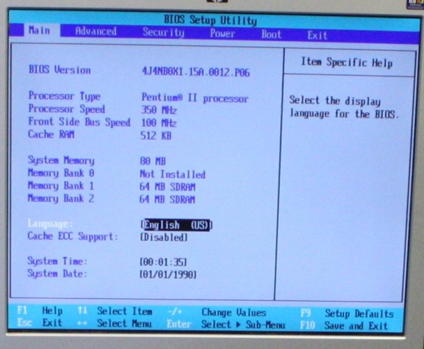
2nd try came up with the Gateway logo, then froze. [1]
Kept cycling, sometimes it gets a fair way in. I got into the BIOS setup (F1 key.) [2]
Set the date/time.
Set for verbose full diagnostic boot.
Observed it's recognising the HDD correctly! Cool. [3] Maybe my guess is right?
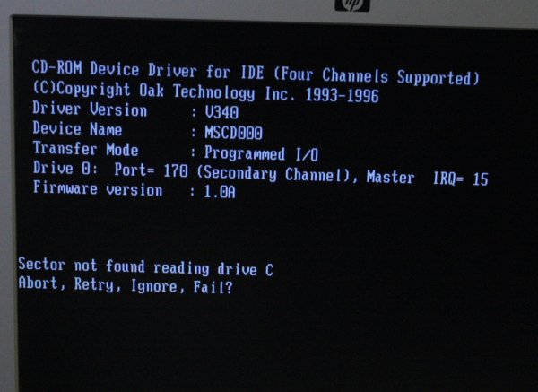
After that it would begin boot from the HDD but fail at random early points. Some errors seen:
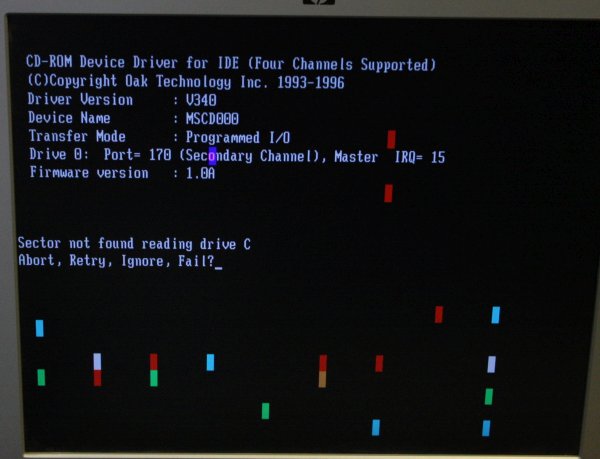
And shortly after, while I'd done nothing, the screen got some wild-CPU writes, and the machine was crashed. [5]
 |
 |
 |
 |
 |
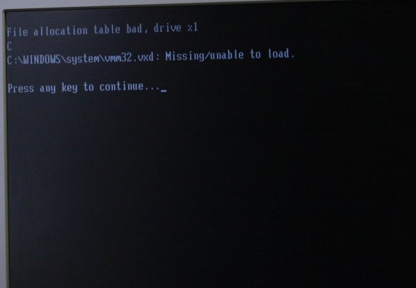
Reached the MS Windows98 splash screen, then hung. [1] But it suggests the HD can sometimes work. Hopefull!
Another boot attempt [2]: File allocation table bad, Drive %1
C:\WINDOWS\system\vmm32.vxd: Missing/unable to load.
Press any key to continue...
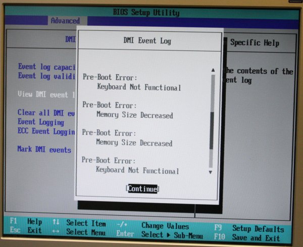
The BIOS 'DMI event log' shows multiple "keyboard not functional", and a few "Memory size decreased" errors. [3]
But they have no timestamps, so don't know if the memory errors are related to system scrapping. I cleared the log.
I'm getting the feeling this is flakey CPU/MB, not HDD related. It's making me very nervous leaving the precious HDD attached to a machine prone to wild CPU crashes. What to do?
What I should have done initially: Disconnected the HDD, tried booting UBCD on CD. It boots to the first banner line on screen, then freezes. (At least the CDROM drive seems to be OK)
By now I'd noticed that as time passed it seemed to be getting further on each boot. Perhaps depolarized electros in the PS or MB, that are improving with applied power? I should check the supply rails with a scope. But for now I just left it on for a while. Lazy, plus the older I get the more I hate farting around with 'personal computers' of any kind. I am very disappointed in the direction the technology has taken. Thanks for nothing MS & Intel. You too Apple.
On retry, now it can boot UBCD properly. Looking hopeful!
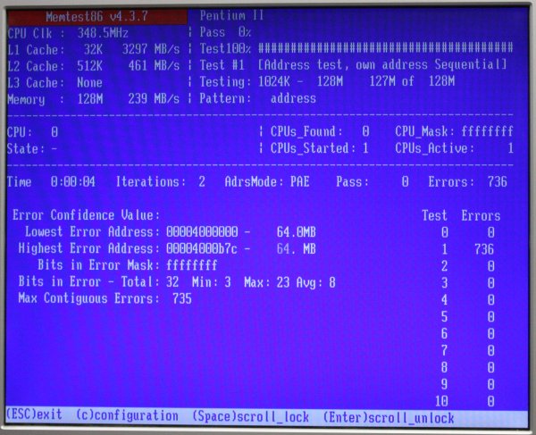
First thing I tried was a DRAM test.
Immediate obvious DRAM fail. [4]
Starts at 64MB boundary and is solid, all bits. So one of the two DIMMs?
I pulled them both, inspected. The 'no name' one has gum stickers on the tracks side - Hmm.
Put just the 'better' branded one in, in slot 0. Rebooted, ran test, now it's fine.
On a hunch I cleaned the stickers off the no-name DIMM, put it in slot 1, booted.
Ha! Now there are 128MB of good ram that passes the mem test. Boo to slightly conductive aged sticker glue. The hunch was from another instance I'd encountered last year, of 'bad glue' going conductive on a PCB.
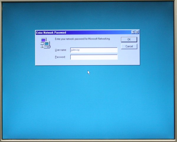
Reconnected the HDD, now Windows boots fine [5] (except I'd forgotten how bloody slow Win98SE boot was, and for a while thought the machine had died.) A stroke of luck — the Windows login password is not used — just ENTER.
 |
 |
 |
Win98 screen res setup says it can do the res of the old LCD monitor I've plugged in. Try it, doesn't work. I have to
drop back to the next lower res.
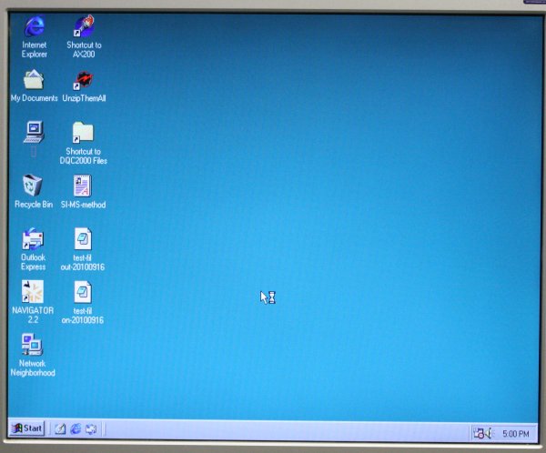
[1],[2] Looks good - there are utilities and work files from the mass spec, turbo pump, etc. WOOHOO!
Now how to back them up?
Tried a USB stick in the sockets - nope. Win98SE doesn't have drivers. Someone has installed a USB driver for an old cruzer thumb drive, but that doesn't work with the two thumb drives I tried. (One of which is a cruzer, but probably a lot bigger than whatever the old one likely was.) I couldn't be bothered hunting for an old sub-1GB thumb drive and trying it. I recall Win98SE had really crap USB support. Near to none really.
OK, take 2. Can the 'Maverick' BIOS access standard hard disks?
Picked an old 10GB hard disk from the pile of spares. Formatted it on my USB dock as one 10G extended FAT32 partition. Copied Irfanview and ZTreeWin to it (unreasonably hopeful they'd run on 98SE).
Rearranged the cables in the Mass Spec PC to access the spare IDE plug on the CDROM drive cable.
[3] Jumpered the drive to be a slave, plugged in, booted. It appears! (Phew. 98SE can read 10G drives, good, I wasn't sure.)
Irfanview works, ZtreeWin doesn't. Bugger. Wanted to copy files with that, since it retains original file dates.
Used Windows File Explorer to copy all the obvious folders of stuff to the transfer drive, which of course results in screwed file dates on the new copies (set to present date). OK, this is just first quick attempt.
Transfered files to my PC via the drive in a dock. That works too. And there are the Mass Spectrometer application files, what seems to be a manual, and brochures for the system. Wonderful!
Even better, the application (AX200.exe) runs on WinXP. So it appears it may be just a standalone EXE, with no helper files put in the System folders.
 Some actions with the interface produce an error popup, but I hope that may be due to the absense of the interface card and non-allocated IRQs, etc.
Fingers crossed it's unrelated to the missing 'Maverick' BIOS.
ToDo:
- Find a disk partition image archiver that works in 98SE. To make a thorough raw sectors backup, in case there are obscure DLLs or something that I've missed. Also do an all-files zip archive, to preserve file dates.
- Find an old suitable PC with more sensible form factor. At least one ISA full length card slot, PCI/AGP for graphics (or inbuilt graphics), equal or better CPU, network port, USB2, WinXP runs on it.
Set up to replace the original 'Maverick' junky PC. - Keep searching for online references to the 'Maverick' custom BIOS.
- If the interface card works in other PCs, I can just forget about 'Maverick'. If it doesn't, then I have some code tracing to do.
Seeking the Manufacturer
I'd started searching at the outset. Developments were not encouraging, which lent the Hard Disk recovery more gravity.
 Googling 'Anglo Scientific Instruments' brings up
http://www.angloscientificinstruments.com
← The rather minimalist web site lists contact information in Britain.
However the company does not seem to be active.
This may not be the same company:
https://beta.companieshouse.gov.uk/company/03914022/officers
The site has no dates, not even the 'News' section. There's ONE mention of "June 2011" as future tense in a News item.
I'd started a discussion thread here: http://www.eevblog.com/forum/repair/restoring-a-mass-spectrometer-maybe/ and a forum member in the UK tried the phone number. Apparently it's dead. They gave me the companieshouse.gov.uk link, noting that there's no listing for 'Anglo Scientific Instruments' as such.
I'd sent a couple of emails to ASI, asking if schematics were available. After a delay I received one reply, giving me a circuit for the electrometer amplifier of a different (similar) unit, and the news that spare filaments are still available. Also mentioning that my DQC2000 was probably one of the last ones made. There was no further response.
Filaments are:
Thoria coated iridium filaments quantity 2 per pack.
Filaments are still available GBP £140-00 per pack.
Anyway, it seems fair to assume the company no longer exists. It's a toss-up whether even spare filaments could actually be bought, given the poor responsiveness of the email address. In my last email I specifically asked if they had any objection to me posting technical details of the DQC2000 online. No response.
Result: I feel free to mention any technical details of the system I have.
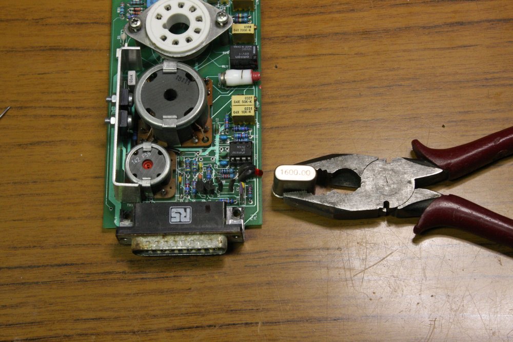
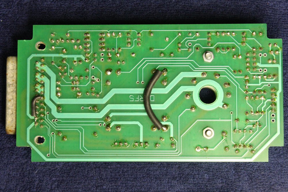
RGA Drive Electronics
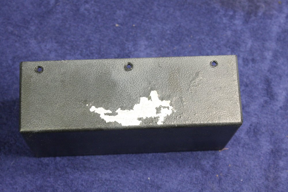
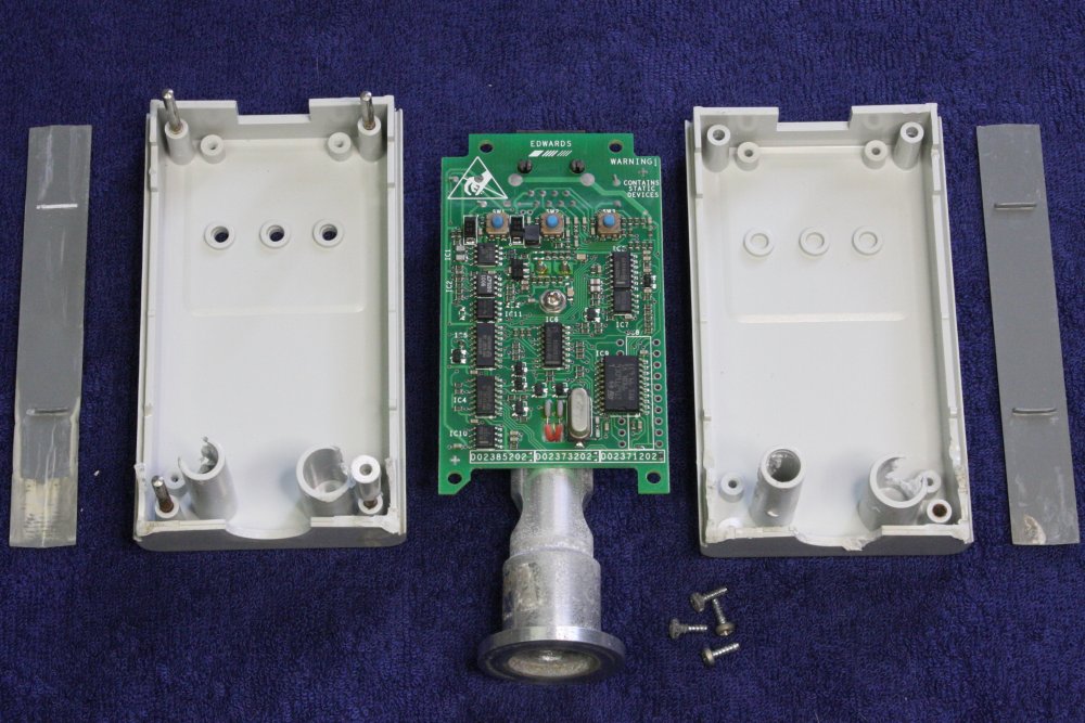
20170125 — 20170129That small black box that was attached to one arm of the vacuum cross, was fully exposed to the weather. So of all the electronics, it fared the worst. And it's the most critical and delicate. Restoring this will be central to the whole project.
 |
 |
 |
 |
 |
1. This box just pulls off the RGA plug, no securing screws. The slot keys it to a pin on the RGA side.
The case doesn't look so great.
2. Well, it could be worse I guess.
3-5. OK, it's pretty bad. Actual water flow stains. Rust. Plenty of sometimes wet dust. But... it seems like the water didn't flow on the PCB at all, so maybe this isn't a lost cause.
 |
 |
 |
 |
 |
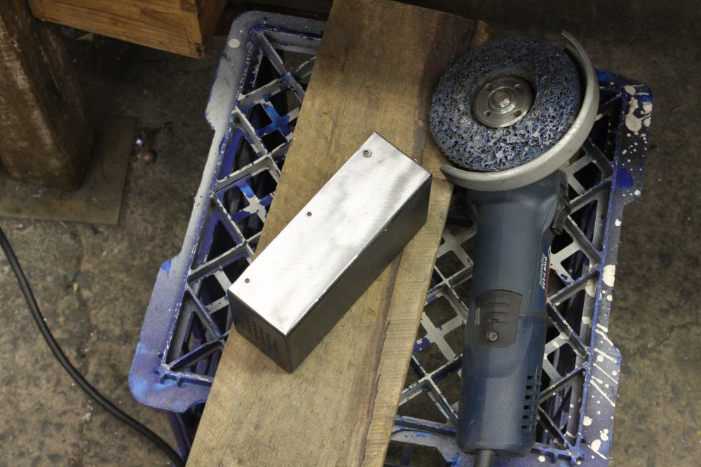
1. Hopefully, the paint will clean up OK.
2. Nope. Corrosion under the paint, dammit. Which I could either ignore, or strip and repaint.
3. Guess which. Too bad I can't do that nice crinkle enamel. Plain black spray can paint it is.
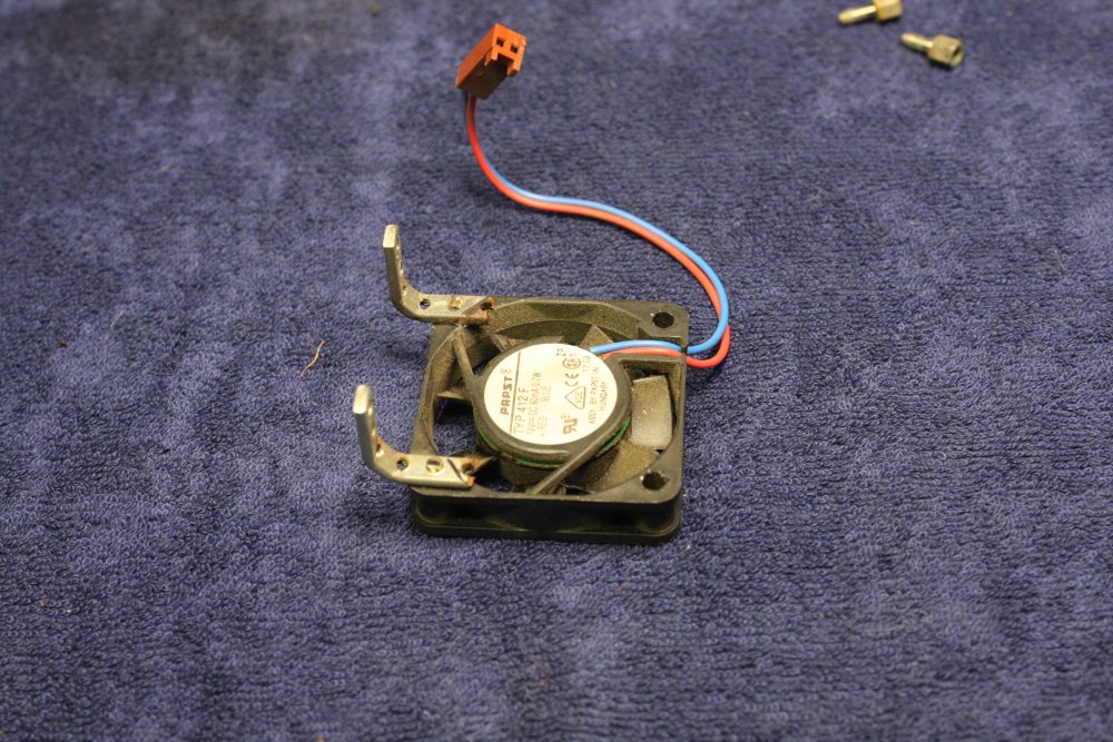
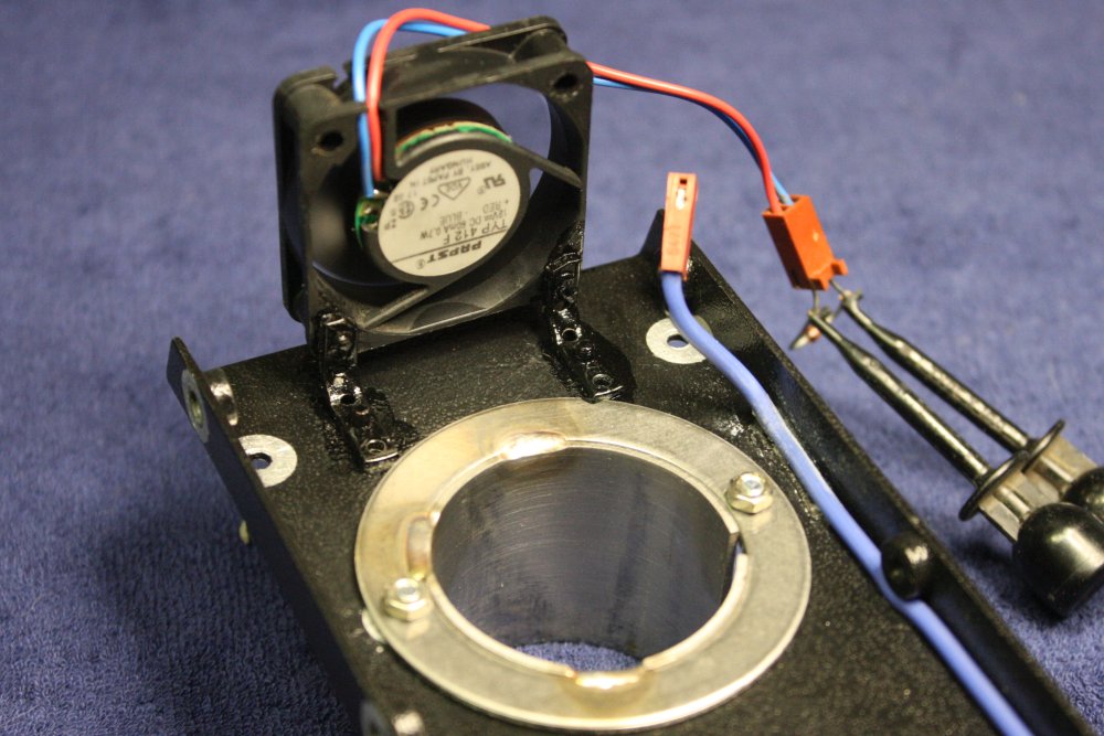
4. The fan's not toooo bad. It runs. And those little brackets are little, but did they have to cut them so roughly?
5. Better. That's black nail varnish btw.
 |
 |
 |
 |
 |
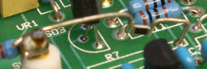
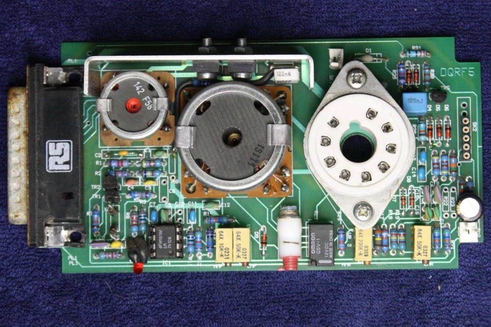
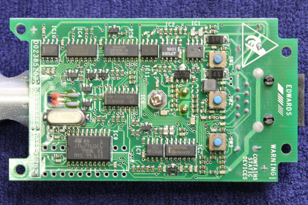
1. One good thing. The sensitive detector amplifier had its own little shielding case, so it's clean. The input node from the RGA assembly is the tall teflon post pin, which extends through to a springy contact pin. Looks like R7 is the primary feedback resistor to that summing point, and extreme measures are being taken to avoid surface leakage.
So why did they lay out for a physically long R7 (precision high value R, presumably), then use that little surface mount thing?
Hmmm, speaking of which, using thick wires like that, joined to a tiny component by small solder butt-joins, seems like asking for joint failure to me. Solder has very little mechanical strength, and those wires will have had residual strain after the ends were soldered.
2. I took another photo. Also looking at that resistor... even without high magnification, one of those joints looks funny. Is that a thin dark line I see?
Also amusing to see such a nubie board outline goof (obstructing the other screws) and dimensions error on the board mount screws.
The board appears to have two gain settings, selected by the reed relay. And it has layout for one more (RL1) not used.
I should have got out the microscope and had a look at that suspect joint first. Instead I just touched it tentatively with a scalpel point. And the wire moved while the resistor didn't. I pushed further ... ha! That joint had been entirely separated. And actually, you can sort of see the break in a blowup from the previous photo.
Well... Did that fracture back when the machine was in use? Because it's a drop-dead fault, making the machine totally unworkable. In which case maybe that's why they threw it out, since the users would not have known how to locate and fix this. So maybe it's great for me, as implying the RGA sensor itself is OK.
But, the question is, did the solder break (which I can resolder), or did the metalization break off the end of the resistor, making it unusable?
That resistor has no value printed on it. Nor does the PCB silkscreen. Trying to measure it with a multimeter gives 'open circuit'. Which I kind of expected, it will be something very high, beyond the meter's capability. I then tried a HP 3456A meter, which should be capable of going up to 1 Gig-ohm. It too thinks this resistor is open circuit.
Hmm. Microscope examination next, as well as asking around.
Later: I'm informed it will be either 10G or 20G. So measuring it (broken or not broken?) will be interesting.
3. Meanwhile I want to get this little board off the mounting plate, and that central pin is part of a feedthrough integral with the plate. So has to be unsoldered. Then the pin pulls back through the teflon cylinder.
It has to come off for two reasons: 1. Circuit tracing. 2. Surface cleaning and bakeout. Sitting in a damp environment for years will have made all the surfaces contaminated and conductive. Relative to the needs of this amplifier anyway.
4. All apart.
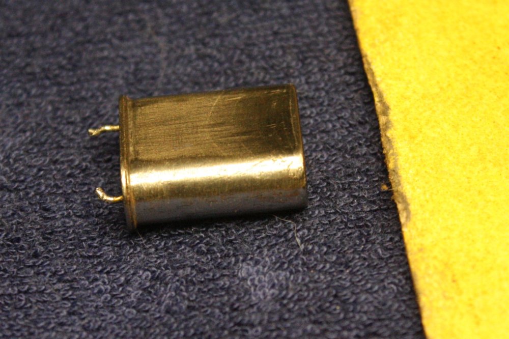
5. Both the D25 connector and the steel crystal case are very rusty, and have to come off. The connector I'll replace, the crystal I'll clean (gently!) and resolder. Since it's certainly calibration critical.
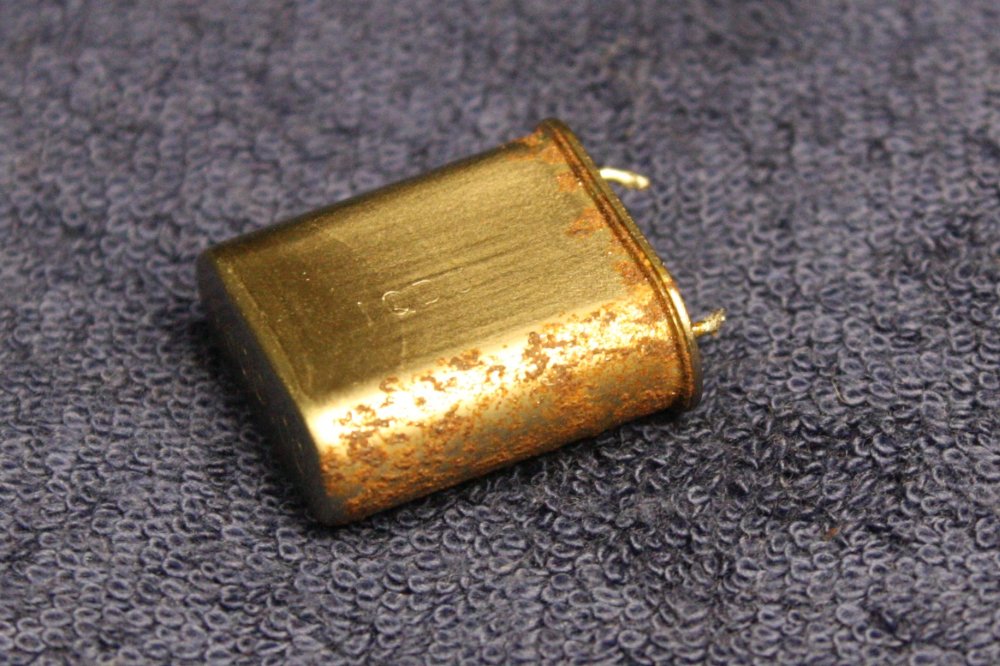 |
 |
 |
 |
 |
1,2. Poor crystal! Sanding reveals the corrosion is quite deep. Hopefully not all the way through the steel case. It's currently stored with the other parts, greased to stop it rusting more. I think dipping in enamel might be best. One thing that surprises me, is that the case was not grounded. Typically if you want stability from a crystal, grounding the case helps. By both shielding it from external noise and forcing a uniform capacitance from the oscillator circuit to everything else. If I knew the calibration proceedure for this thing I'd ground the case. But since I don't...
3,4. Circuit board views. No obstacle to circuit tracing here either.
5. After the outer case repaint. Yes, the bare metal areas around the screw holes (case grounding continuity) are still clean.
ToDo: (quite a lot)
- Trace schematics of both PCBs. Will have to remove transformers to characterize them.
- Desolder and replace rusted D25 connector. Note mounting screw holes are hacked.
- The electrometer amp board - surface clean.
- That resistor - microscope exam.
Test & fix/replace 10/20G resistor & mounting. Use thin wire on one end this time.
After all soldering done, re-clean resistor and posts. IPA wash, bake. - From schematic, test functions. What are the adjustments, and can I derive a cal proceedure?
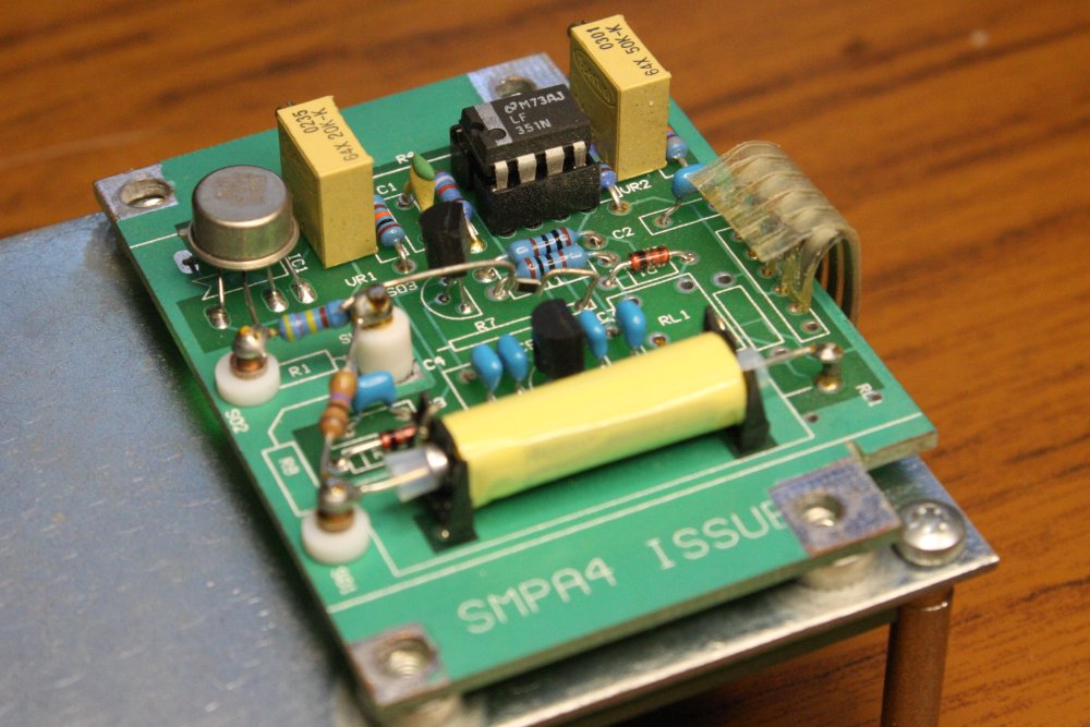
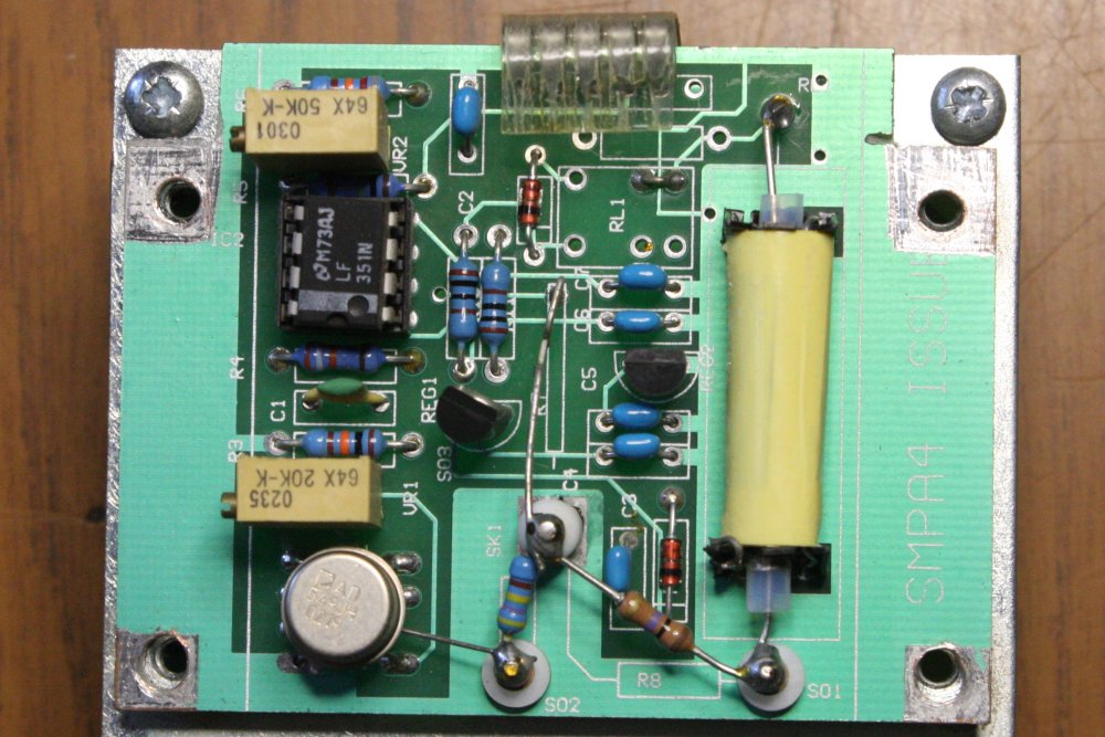
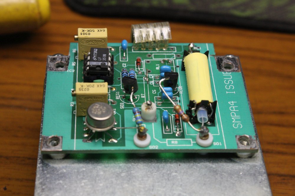
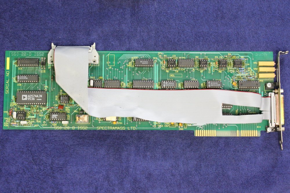
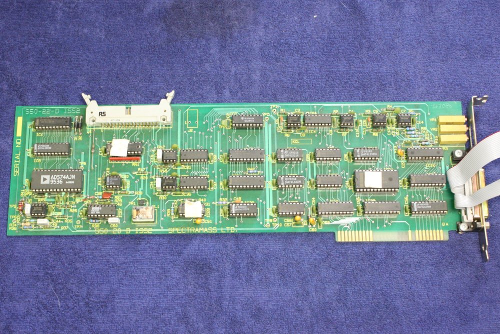
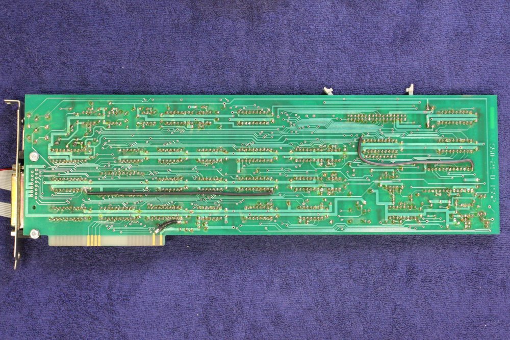
RGA PC Interface Card
20170125This is the ISA slot card from the PC, that provides all software interface to the RGA. Not much done on this at present. Most of the work is going to be in deriving the schematic. And fault finding, if it doesn't work.
 |
 |
 |
 |
 |
1-3. You can really tell when a circuit board is designed by people who aren't much good at it. Lay out the PCB before you decide on a pinout of the connector, then have to hack the ribbon cable, why don't you. I'm entitled to say this, because I spent many years of my professional career designing circuit boards, and I did NOT make this kind of goof, ever. To say nothing of the layout needing that ribbon cable at all, since maybe it just wasn't possible to rearrange things to avoid that. (But I bet I could have.)
What's with all the different company names? ASI, Larimax (in the brochures), and now Spectramass on the PCB. Methinks someone was playing stock listing and shell company games. Yet they couldn't get it together to make a simple sheet metal PC card bracket. They just repurposed an existing one they found somewhere, despite it not being right.
Using thickish PVC insulated wire for patches is another giveaway of amateurs. Kynar or teflon insulated fine wire-wrap wire is far superior. And tack-glue it down, please. Also the board is hand-soldered, so they were doing one-offs, or very small runs. Fair enough, but washing the flux off would have made it look a lot better.
Also... IC sockets. This is what you do if you are going to provide servicing information to customers. Because sockets make IC swapping easy, but ALSO greatly decrease reliability. I don't see any sign ASI/Larimax/Spectramass were generous in handing out schematics and tech info. Mr "Maverick" says quite the opposite — they were secretive and mean.
4, 5. Their repurposed bracket was meant to use a screw hole as screwdriver access for one of the trimpots. But it isn't lined up, so fail. While I had the board out I cut away some metal to fix that little problem. If I didn't it would have been highly annoying sometime in the future. I should mention that the Gateway PC with its riser card and Slot-1 CPU, make extracting this interface card a major pain. Was that intentional, or just accidental really poor design? Don't know.
![]() ToDo:
ToDo:
- Reverse engineer the circuit. Quite a bit of work in it, but no obstacles.
- Just a thought. If I can get this RGA system working (which implies having the circuits derived, and software captured in a stable, maleable form), then a question to look at would be, can an equivalent RGA quadrupole head be designed, that could be manufactured by hobbyists? Because all the electronics I see in this system could definitely be made far smaller and cheaper these days. All the digital circuitry would collapse into one very cheap FPGA, and all of the circuitry packed into one quite small box attached to the actual head. With just a DC supply and a USB or ethernet channel to a PC. The sort of thing that could be done as an Open Hardware project.
Ha ha, if I ever had the time.
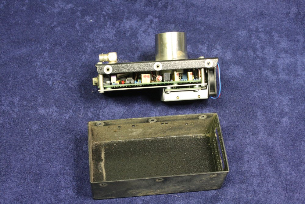
RGA Interface Box
20170127
This is the rackmounted interface between the card in the PC, and the quadrupole driver module that sits on the vacuum head. It appears to be mainly some power supplies, including one HV multiplier.
It has a rusted front panel, and has been dropped at some time in its life on a corner, mangling one of the mounting holes.
Here I'm taking it apart to clean and evaluate.
 |
 |
 |
 |
 |
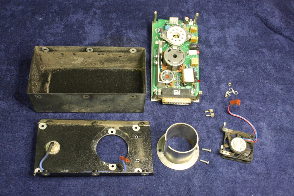
1. Internal layout, pretty simple. Dusty, and the torroidal transformer was quite loose, probably from the time it was dropped. The screw is bent, and also is not the right thread for the nutsert mounting on the baseplate. So the threads on both are kind of stuffed.
2. The only PCB. Simple, will be easy to trace out the circuit.
3-5. Part of the problem with the transformer mounting is there's no solid centering. So I cut a fat puck of Delrin to slip over the mounting screw. It's a press fit in the end of the toroid core hole.
 |
 |
 |
 |
 |
1. I'd re-tapped the thread in the baseplate nutsert, and found a suitable replacement screw. Transformer now securely mounted.
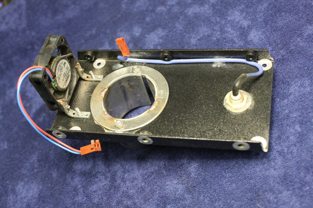
2. What to do about the rusty front panel? I don't want to lose the silk-screened text. Most of the rust spotting cleans off OK, but along the bottom edge it's so badly rusted that repainting is the only option. For cleaning, paint sanding and respray, I want to remove the panel from the rest of the box.
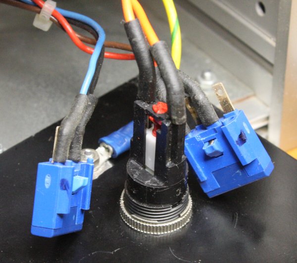
3. Only I can't figure out how to remove it! The power switch MUST come apart somehow, but how? I don't want to desolder all the wires, potentially damaging the delicate switch. Much too late, I did figure it out. There's a little red slot screw hidden in among the leads. Turn 90 deg to release the side switch blocks. Still need to desolder 2 wires.)
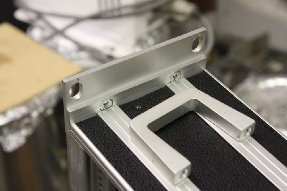
4,5. Also I want to remove that bent front bracket, but can't figure out how it comes off either. There must be something under those black side panels, but they are slid into slots in the side extrusions, and cannot be slid out endways without removing the corner pieces. The corners are mysteriously attached to the side extrusions. The black strips are thickish aluminium with vinyl stuck on, so they can't be warped out. Chicken and egg?
 |
 |
 |
 |
1-4. Ha ha, this is comical and frustrating! I really can't figure out how a simple metal case comes apart. Neither can anyone else in a discussion thread about it. All comments I've tried. The only way I could imagine this being put together, was using some kind of non-removable springy barbed spikes into holes in the side channels. But that would be a completely insane way to do it! So... what?
 |
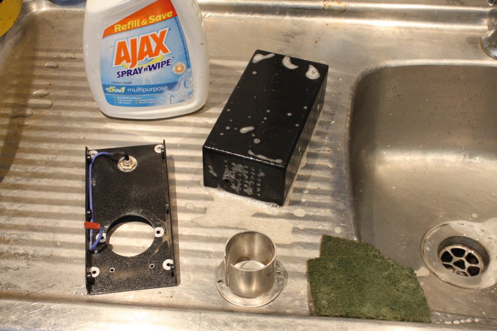
 |
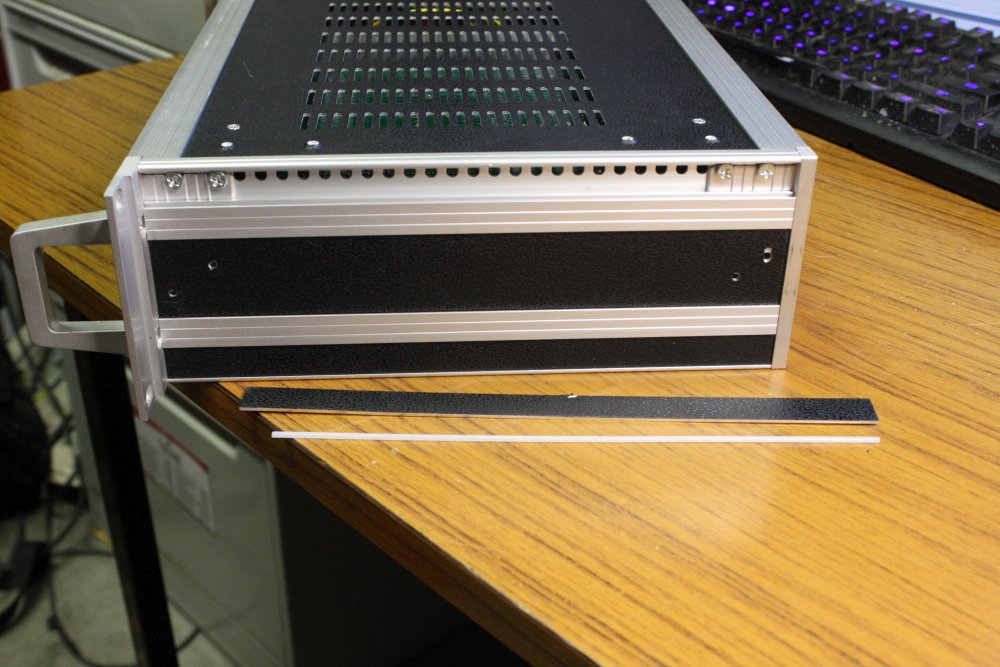 |
1,2. I gave up, and just did the necessary work with the box in one piece. Black spray paint along the sanded bottom edge of the front panel. Masked with tape and newspaper, and I only had gloss spray paint, so it's not perfect. But at least no more rust.
The bent corner I mashed back into shape with punch, hammer and backing blocks, enough that it fits in a rack. Could not restore it to neat-looking, since to do that I wanted the bracket off, so I could TIG-weld on a new blob, then machine/file to shape. Not going to TIG weld it while attached to the case with electronics.
3. After it was ALL FINISHED, someone casually mentions on the forum thread that the secret release trick, is to lever the top and bottom side panels inwards, compressing a small springy rubber tube in the inner groove. Quite a lot of force needed to squash the whole length of tube.
Yes, that is it! Thank you. Grrr... I don't feel bad for not guessing that one.
ToDo:
- Trace the circuit, to nice SCH.
- The steel TO3 transistor cases are a bit rusty. Clean & coat.
- Front and back panel screws are M2.5, 10mm pozidrive pan head. Replaced the worst rusty ones with misc screws, but would look nicer in stainless. PF doesn't stock, buy via aliexpress, etc.
The Decapitated RGA Head
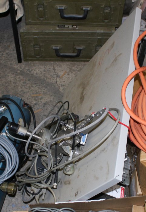
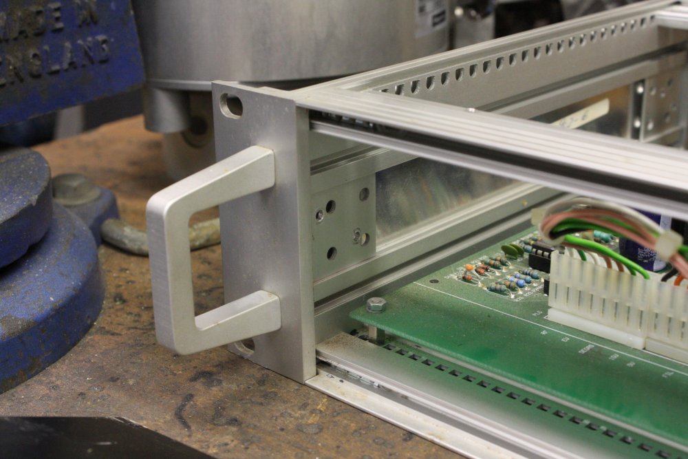
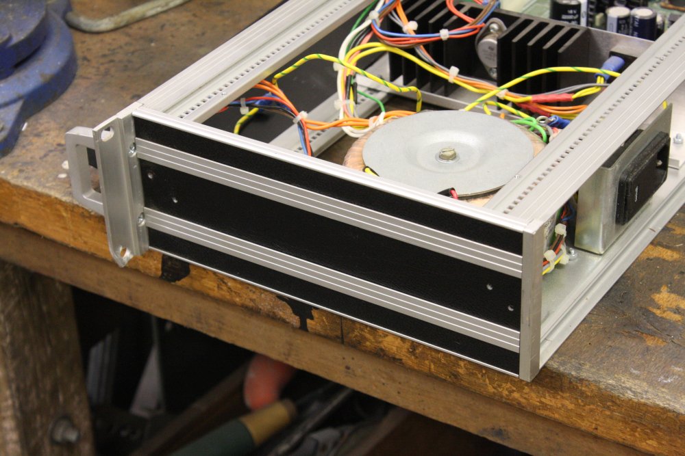
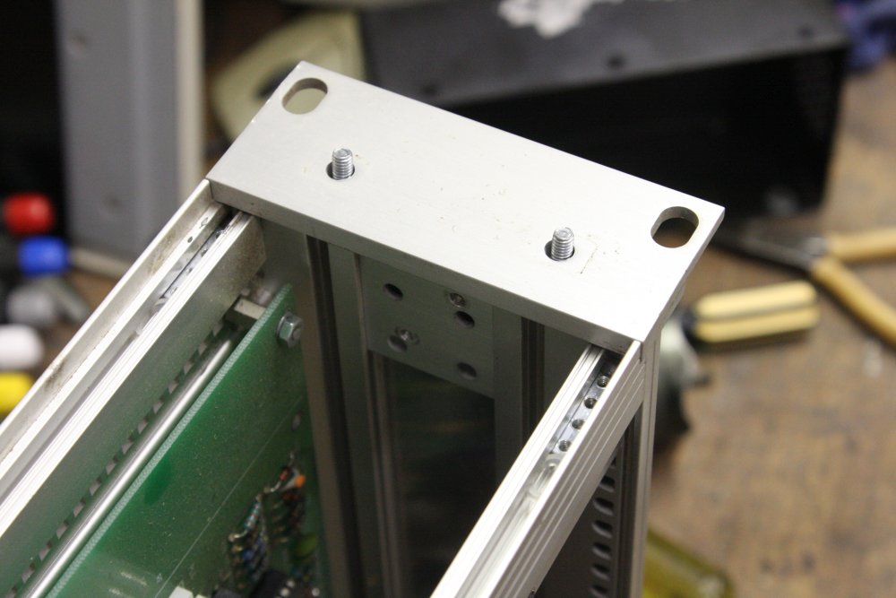
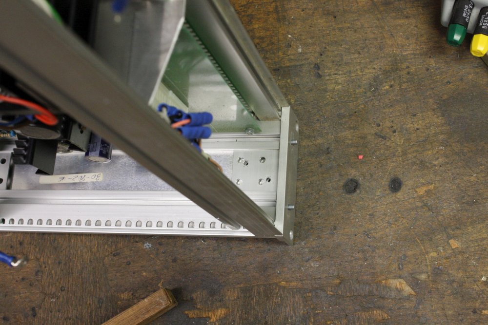
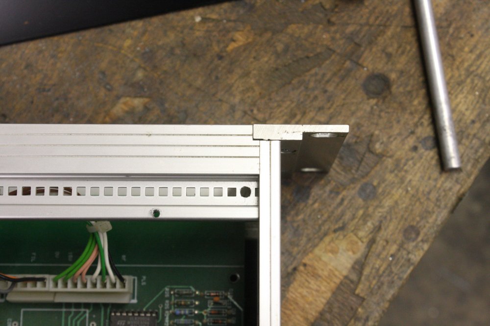
20170127This is one awkward shaped piece of treasure. It's too big to put anywhere but on the floor — where it's exposed to accidents. Doing something about this was urgent. I'd already decided I'd have to at least temporarily mount it in one of the racks, but not sure how yet.
 |
 |
 |
1. I'd removed the vacuum gauge plug and the RGA drive electronics module, leaving the delicate pins exposed on this thing.
2. Next the heating mantles. These are 240V heaters, for baking out the vacuum section. They are quite tarnished. Whether they include temperature limiting I don't yet know. But they come off easily. All the screws are rusty. If these heaters are functional they will get all new screws.
3. Temporarily leaned up again. No, this is no good. I just KNOW I'm going to accidentally knock something against those pins.
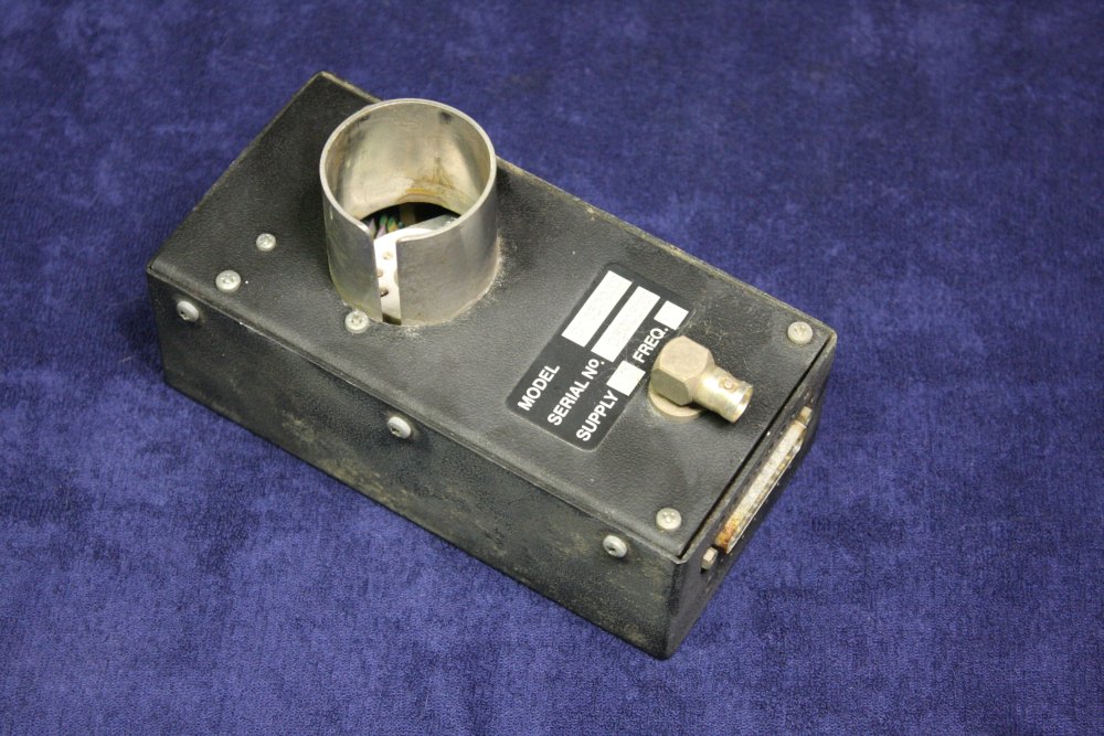
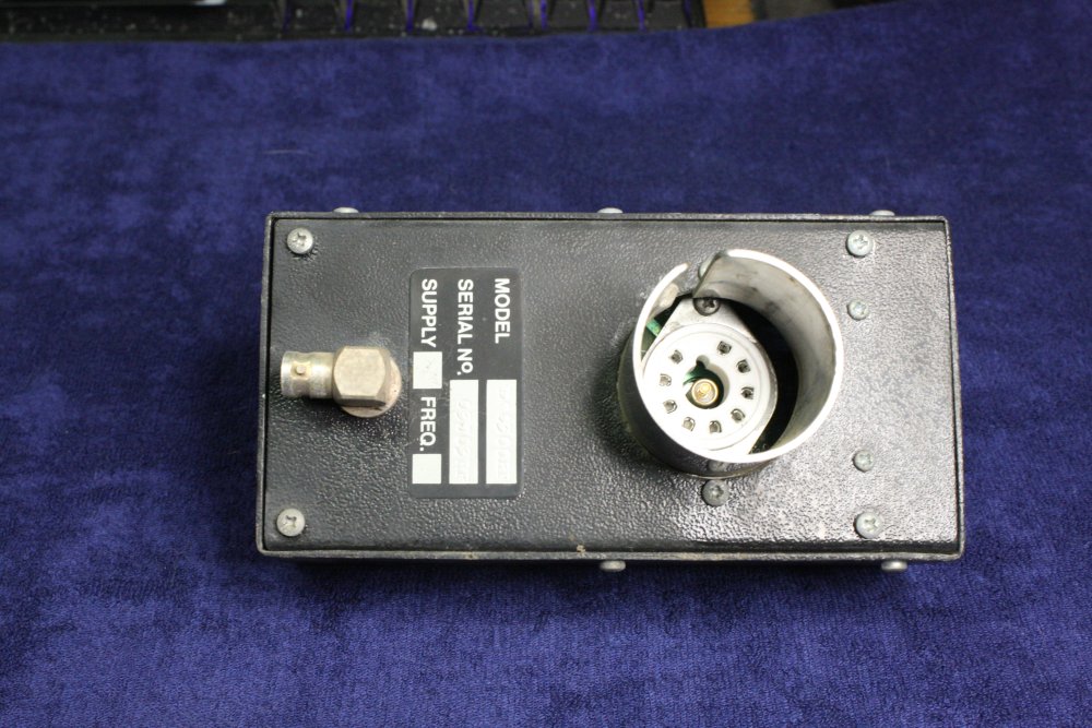
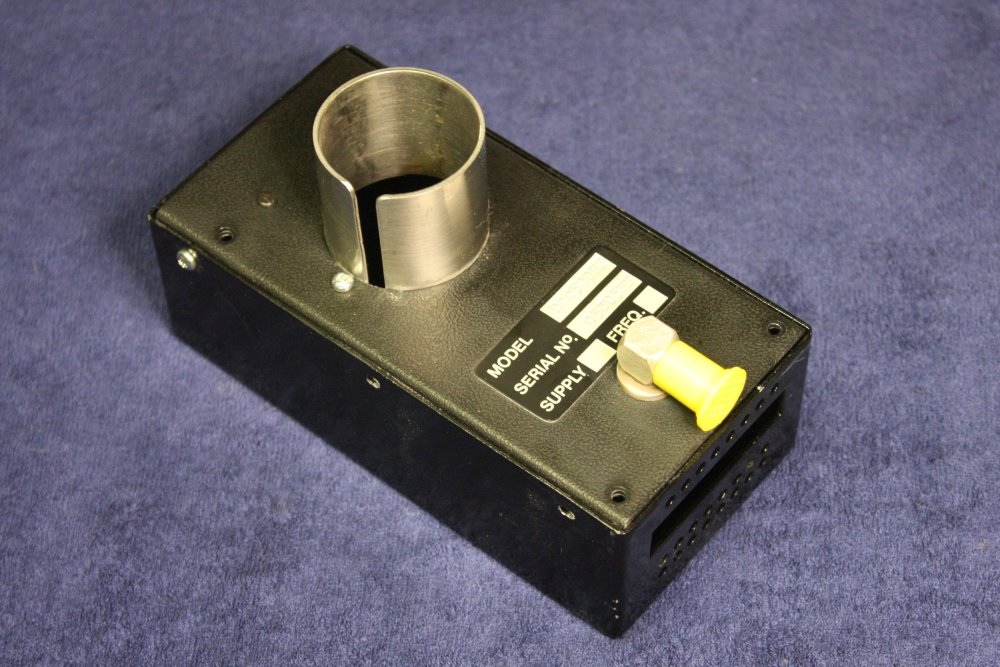
RGA System Power Box
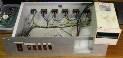
 This is very simple — mostly just a power distribution box with switches for each of the system modules. See here.
It also contains the RGA vacuum gauge readout unit.
Incredibly, the readout unit doesn't fit through the square cutout in the front panel, unless the cover of the readout unit is removed. Someone forgot to allow for the height of the screw heads on top and bottom of the unit. Pic shows it wedged in the hole, stuck on the screws.
Anyway I won't be using this box. It's ugly, a waste of space, and my system is intended to be all automated. Only the gauge unit will live again.
Don't Tell Me Not To Open That
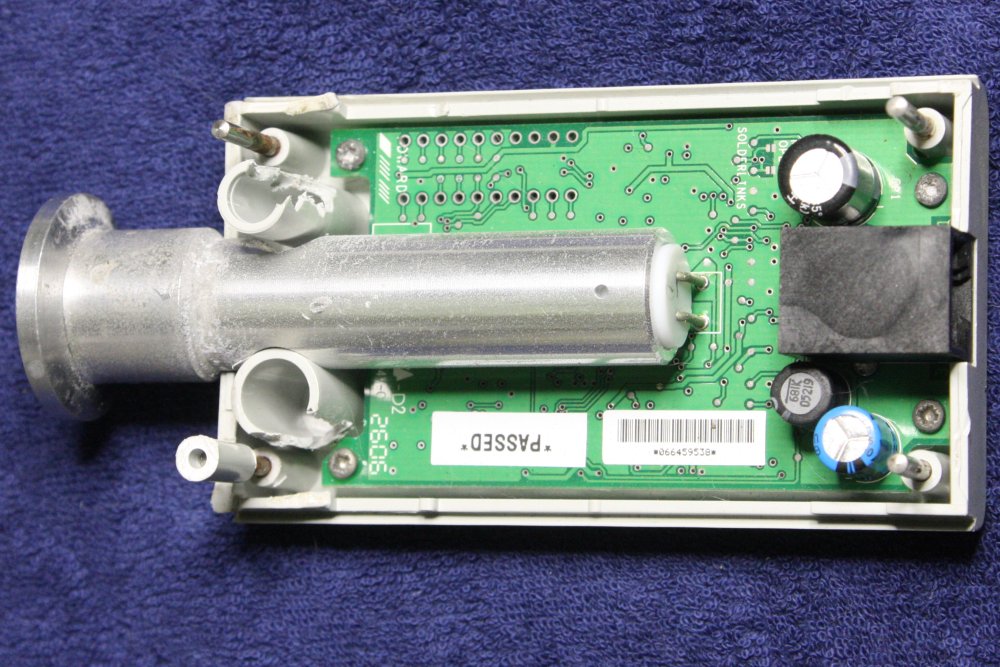
20170130The heavily corroded Edwards APGX-M-NW16/ALI Active Pirani Gauge I mentioned was still lying around, waiting to be evaluated.
|
 |
 |
By chance I decided to look at it the day after I'd learned how to remove the trick side panels from that metal case.
Alright! This sensor has no case screws, but it does have obviously slide-in side strips. Clearly there will be some trick with those, to open the case. Right?
So, I wasted some hours trying to find the trick to removing the side strips from this thing without damage. They look like they could be slid out endways. But they don't want to. Sliding thin shims under them, hoping to press some springy release catch - no luck.
Eventually I lost patience and levered one off by brute force, with a screwdriver under it.
Well waddya know! There is no release trick. They are just locked in place, held there by detents that cannot be bypassed. The case halves just push together, locking them in.
So, how does the case come apart? I tried levering along the seam. It bends a bit, enough to show the seam is not glued. But something really does not want to let go. Peering in the side gaps I could see some kind of corner posts. Hmm... Oh well, more force then. A lot of force. Even more force, levering in the side gaps and wrecking the plastic.... and it starts to give slightly.
Ha ha, when I was trying to open that ASI metal case, I'd wrongly guessed there might be some kind of barbed spikes holding it together, but couldn't believe that because it would be such an insane way to build it.
Well guess what?
That is exactly how this Edwards gauge is put together. The four corner plastic posts have barbed steel spikes, that lock into the posts as it's pressed together. There are another couple of plastic posts that slide into each other, also such a tight fit that they effectively lock. I had to actually cut the sides of those open with an engraver, to get them to let go.
In short, this Edwards gauge is designed to NOT be possible to open without seriously damaging the case. It goes without saying there is no service information available. This is a throw-away item, not meant to be repairable at all.
Which makes it all the more appealing to see if I can fix it. Too bad it is probably kaput. There has been some seriously corrosive substance inside and around whatever vacuum system this was used on. The steel circlip meant to hold in the filter mesh snapped as soon as I tried to move it. Hydrogen embrittlement? The mesh itself is stuck in place, glued in by corrosion of the aluminium fitting. The legs of all the ICs and the spring contacts in the RJ45 socket are greenish, and metal bodies of the three pushbuttons are rusted.
 |
 |
 |
 |
 |
But let's have a go. Finally got around to trying on 20170302, late evening.
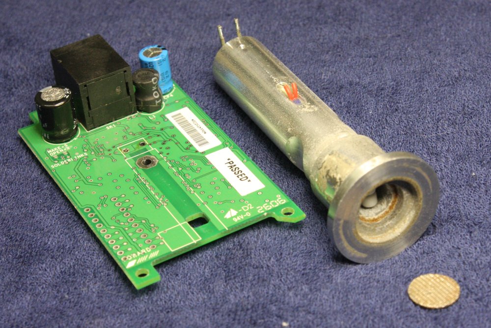
1, 2. Desoldered the cylinder wires, removed it. Got the mesh out by deforming it with a centerpunch. Then hammering it flat again. Wow, the corrosion is even worse inside. Can't do anything about that right next to the extremely fine Pirani wire. But I could clean the outside metal in the lathe.
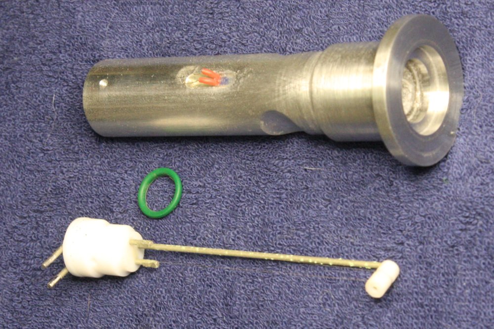
3. Hey, maaaaybe it's doable. Turns out the Pirani wire holder just slides out the back. (Now that the retaining screw is removed.) Can you see the wire? Only just, and on the desk I can't see it at all without a magnifier. Awkward to work with. But now I could clean the inside of the aluminium cylinder.
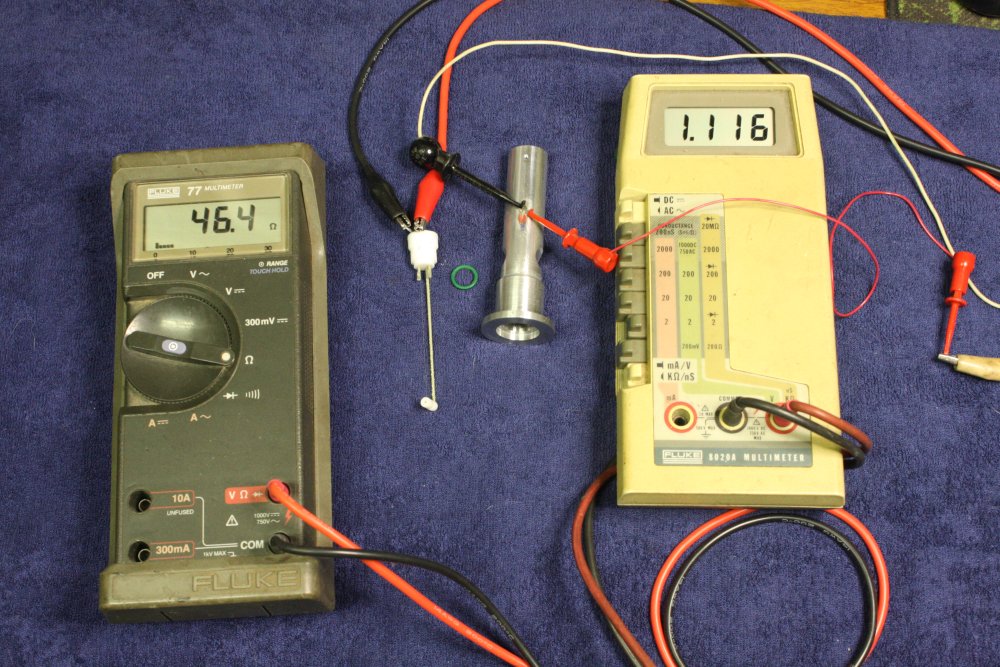
4. Resistances of the Pirani wire (46.4 ohms) and the thermistor embedded in the cylinder side wall (1.116K) at room temp. They are both PTC.
5. Oh well. I should have left this Pirani Wire holder alone, and just cleaned the inside of the cylinder. While scraping the corrosion off the long support rod, I accidentally touched the Pirani wire with the scalpel tip. Felt it, couldn't see it. Never mind, I really don't think this was ever going to work, or know how far out of cal it would be if it did sort of work. The ultra-thin wire seems to have a coating of something presumably meant to be impervious, but it looked (under a magnifier) like there were a few spots of corrosion on the wire too.
Interesting anyway.
Lesson: I shouldn't work on ultra-fine, delicate, so-tiny-they-are-invisible things late at night. (I knew this already, but it was... late at night and I forgot.)
Meanwhile, Back at the Infrastructure
20170203
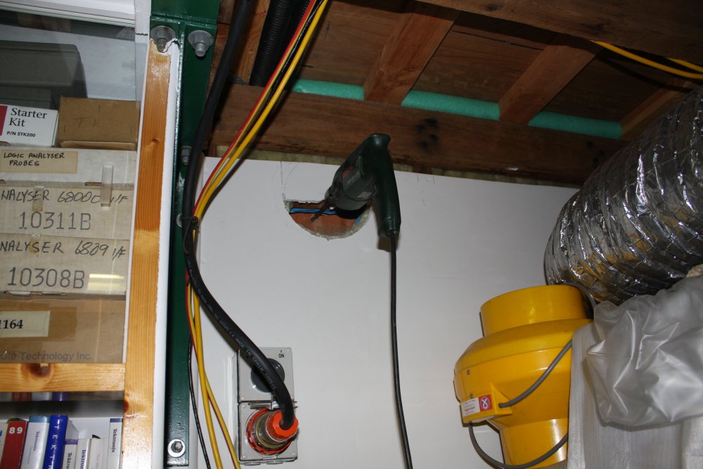
For ages I've been wanting to put in an air extraction duct in the lab. From the soldering desk, exhausts from vacuum pumps, and also from a mini-airconditioner. The plan had been to enclose a duct-space into the ceiling timberwork (the upstairs floor), then out into the wall cavity and up to the eaves, and out a vent in the eaves.
But this was far too complicated, figuring out how to actually do it was taking ages, and there were several drawbacks.
Now the vacuum system project is starting again, I really need to get the air vent sorted out. Also there will likely need to be a water cooling loop, with a heat exchanger outside.
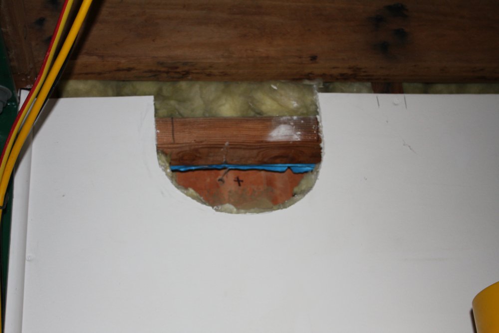
I realised there is a vertical slice of Lab side wall that could be dedicated to 'feedthroughs'. Why not just take the air exhaust duct straight through the wall at ceiling height there? It means cutting a hole through the outer brick wall skin, but that's relatively easy. I have the duct and axial fan, all I need is the actual vent.
Did I mention this is summer? There's been a few weeks of very hot days, which without air-con makes it hard to work. So let's do this now.
 |
 |
 |
 |
 |
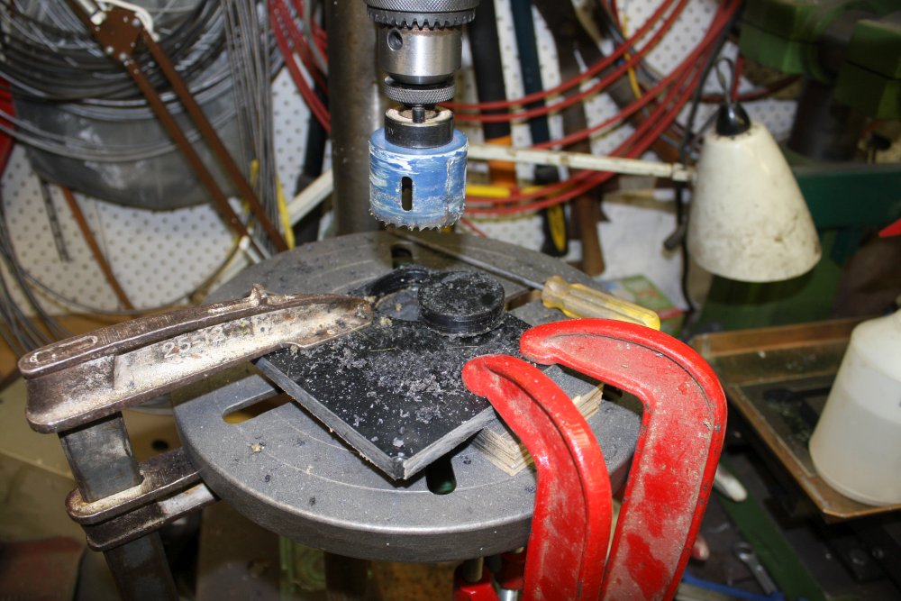
1. I worked out how to make the vent, and bought the stainless steel for it.
2. The exact construction depends on the wall hole details, so some exploration is needed. (I built the building myself, but that doesn't mean I remember exactly where every stud and nogging is, behind the plaster. Or want to dig out 18 year old plans, or trust them, even if I drew them myself.)
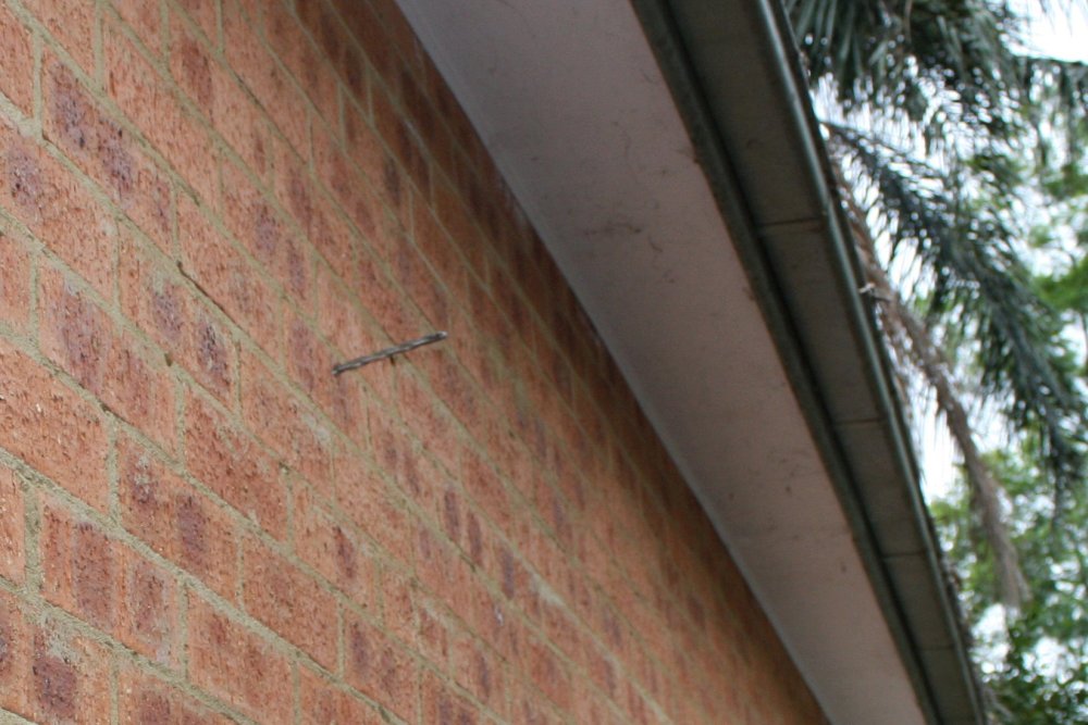
3. The drill hole through the wall is just to give a reference point, inside and outside. The precise vent hole position will
depend on a few things.
4. Of course there was a nogging right there. It can go, it's not structural since the huge rafter beam a few inches above is also tied to the upright stringers.
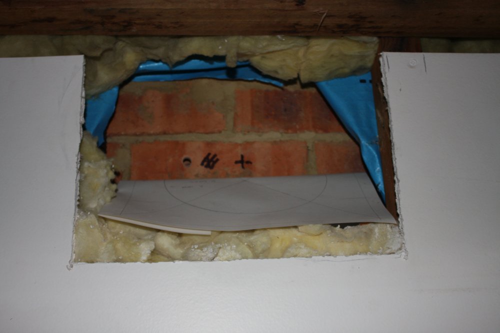
5. Realized the plaster hole has to be large, to access the rear nuts on the bolts that will hold the outer vent frame in place. Plaster hole size is not a problem since there will be a sheet of plywood on the inside to support the blower anyway.
The sheet of paper is a full size puppet of the vent and outer flange. Thinking about where to place it, for optimal brick cut points. Not where it is now!
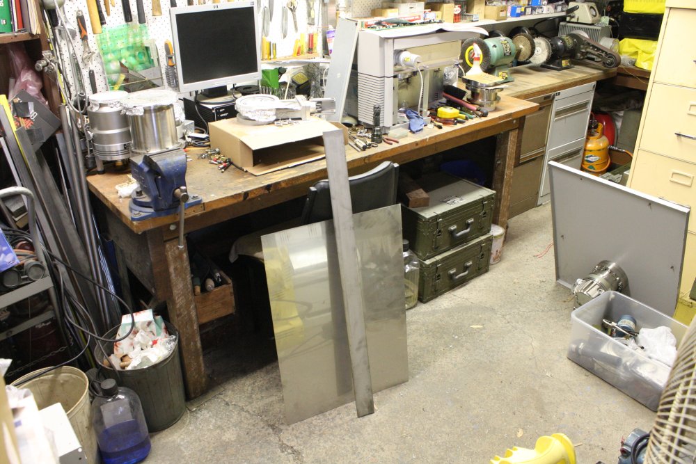
Of course I have to make the vent before I cut a big hole through the brickwork for it. I'll be using the sheet metal machine to roll the flat stainless sheet into a cylinder. Only problem is, I can't get at the machine. The workshop has accumulated too much junk again. Not the vacuum stuff, though that did make the space problem worse. No, I mean real junk, completely useless stuff.
Time for a Cull
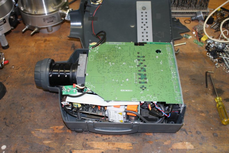
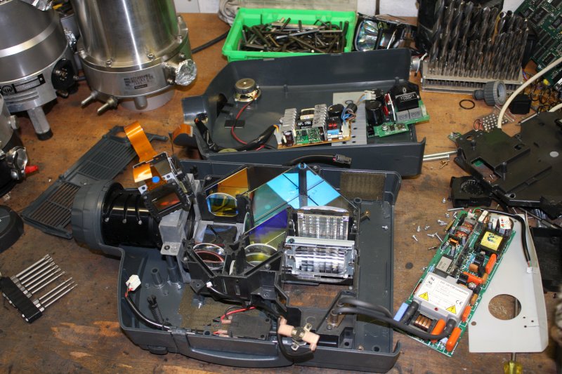
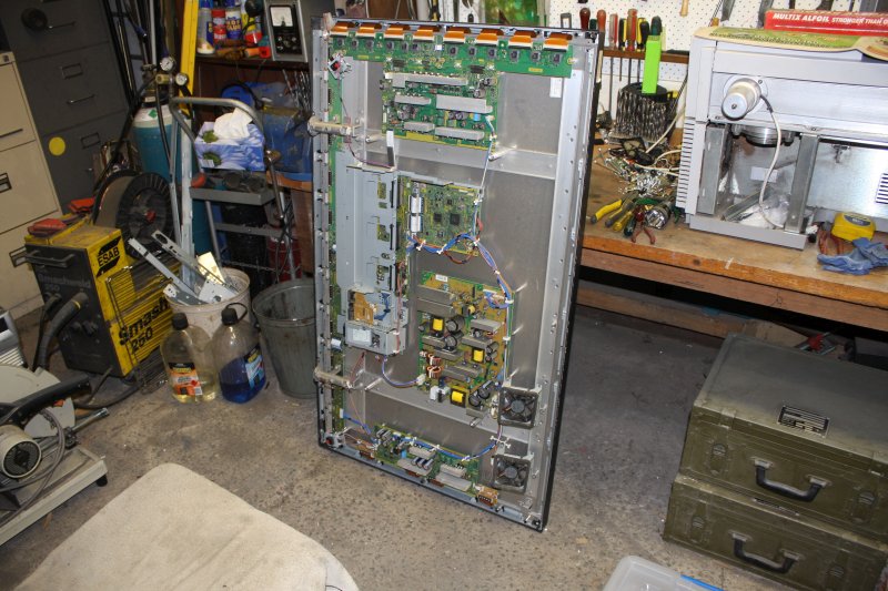
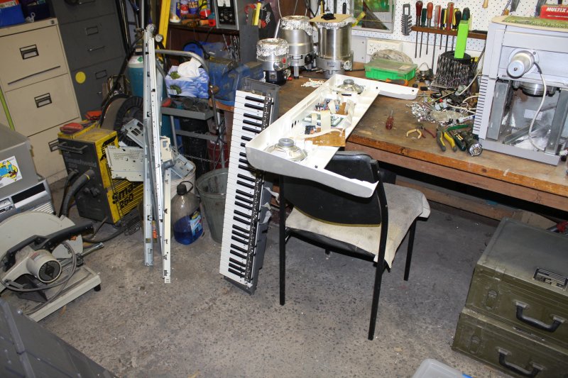
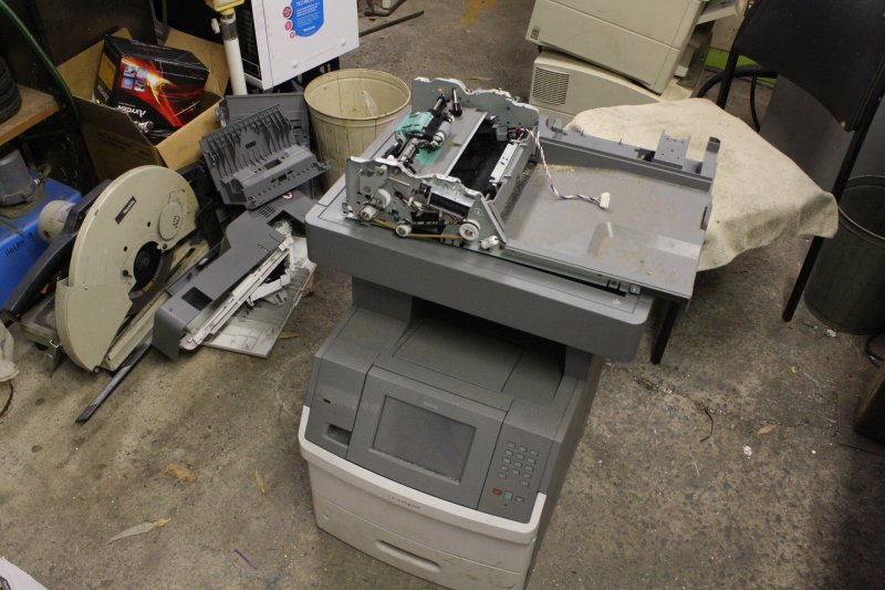
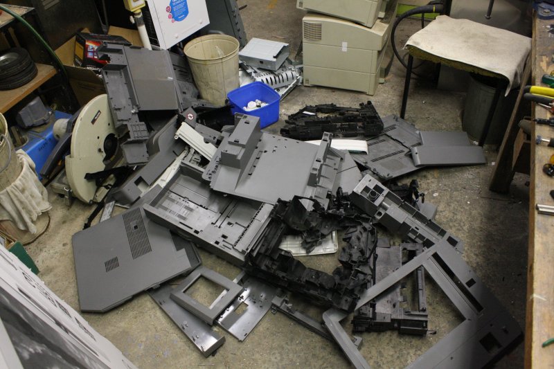
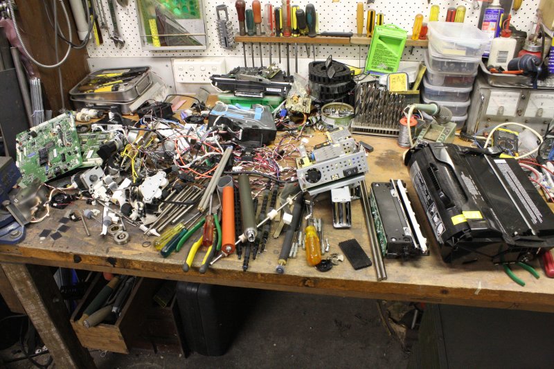
20170204One of my guilty pleasures is picking up interesting looking bits of space junk (stuff that's technical, but no longer wanted) to pull apart to see how it was built, and to maybe salvage any parts I think could be useful someday. Now and then I find the thing is easily repairable, but usually they just get gutted. The downside is I have to watch out, or my workshop becomes unworkable with stuff piling up in the dissection queue. It was getting like that now. Also too much junk in the upstairs storage loft.
 |
 |
 |
 |
 |
 |
 |
 |
 |
 |
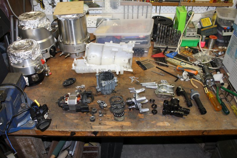
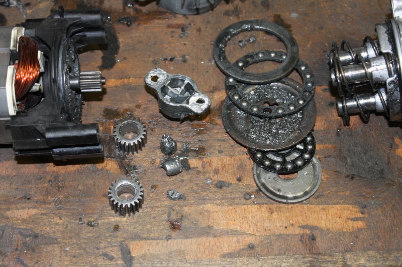
In sequence:
- A water pressure cleaner. Failed due to absurdly weak part in the pressure pump fracturing and grinding spectacularly. Glad I wasn't the sucker that bought this junk.
- A colour video projector, that was high-end in its time (10 years ago.) Was given to me with the Green channel wonky, and at the time I'd attempted to repair, but needed schematics and could not find them. Now it's obsolete and I have better projectors. The optics section is very pretty and the bits go in my 'optics curios' box.
- A huge plasma screen. Works, but missing all the interface cards. Ridiculously heavy. This was leaning up against my sheet metal machine, and the main culprit making that area of my workshop inaccessible. Out it goes.
- Three identical Yamaha keyboards, all with no sign of life on applying power. They all have 'membrane keypad decay' and are not worth attempting any repair. But the actual keyboards are worth keeping. I have a side project in mind...
- A bit later; 20170215. While procrastinating over whether to strip those HP A3 laser printers, see Avoidance Syndrome. They're sitting there in the background, making me feel bad.
A largish Lexmark X652de; copier, printer, scanner, networked office machine. I'd been offered about 8 of these, and wanted to take them all, just for the nice colour LCD screen, to see if they could be adapted to a project. But could only fit two machines in my car at the time, ha ha. They were very dirty on the outside. On trying one, it works apart from some minor copy page defects. And they are clean inside. Maybe could be got working. But it would take a fair bit of work to even find out, and if the faults are serious that would be wasted time. Which I just can't spare atm. It's taking up too much space, so gets the chop.
I'd even found the service manual. It's a pity I couldn't grab all 8 of these machines, as then learning their typical faults would have been worthwhile. The LCD is nice; colour, hi-res, 153 x 94mm (7") with touch. PN FX0700A8DSSWAG02. Made in China, no manufacturer name. They are known by the Net, but so far I can't find data. Didn't try searching for the controller IC data yet. The copier service manual includes the connector pins and signal names, which is a good start. Three pair LVDS interface. So I have two of these, wish I had 8!
Revealing the Mass Selective Detector Treasure
20170205The culling of junk was going well. Not much clutter left. Just a few things to do before I started making the wall vent. (Ha ha ha, sometimes in retrospect I have to laugh at myself.)
The bench was mostly free of the recent vacuum gear influx, but there was still that unknown and apparently incomplete Mass Selective Detector thing taking up much of the right hand end. Now it's time to have a look at that.
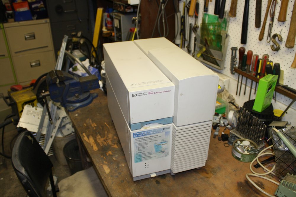 |
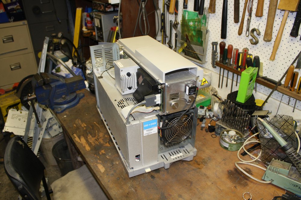 |
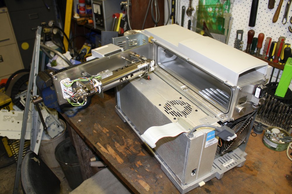 |
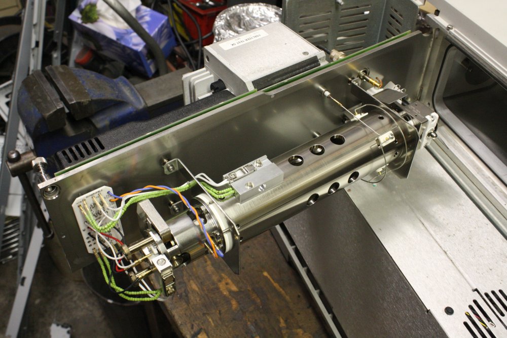 |
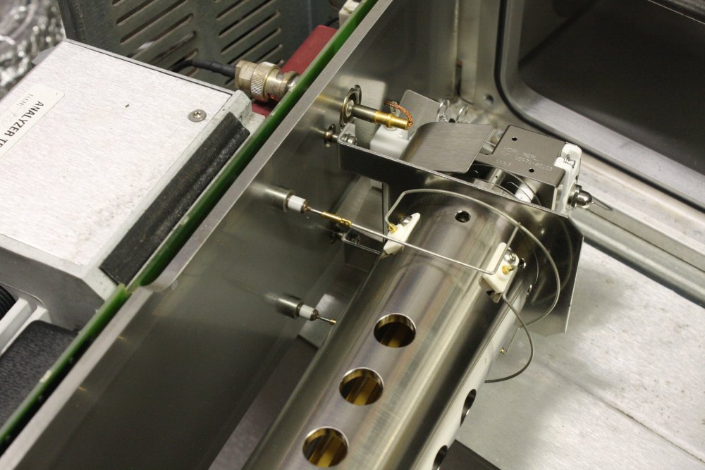 |
1. The box has exactly one control — the power switch. All interface is via a HP-IB connector on the rear.
2. Until I actually tried, I hadn't realized a large section of outer case just unclips and lifts off. Hmm, what's this? That is a thumbscrew right at the front. When I first saw that it was actually fully undone. So was its mate on the rear corner of what is obviously a hinge-out panel. Leaving several plugged-in cables as the only thing preventing the panel from being swung open. Odd, why would someone undo the thumbscrews, but leave the cables plugged in? It's hard to guess.
3. With no idea of what to expect, I undid the cable connectors and carefully swung the panel out, feeling for any interference.
Wow. You know that scene in the movie Pulp Fiction, where Vincent opens the briefcase, and his face literally lights up with a golden glow from inside the briefcase? We never found out what's in the briefcase.
Well, you can call me Vincent. We happy. Phew. And you get to see what's inside this briefcase, so you happy too.
4, 5. Because of the Anglo Scientific Instruments RGA, I'd been reading up on Quadrupole Mass Spectrometers. So at least now I can recognize when I see one. And when I see one in which no expense has been spared, to make it as absolutely amazingly over the top as possible. Like this high vacuum precision physics jewel.
My God. Someone threw this out. In the rain. Humans never cease to amaze and appall me. Quite a long time ago I decided I don't want to be considered part of that family/species any more. This is just another reminder.
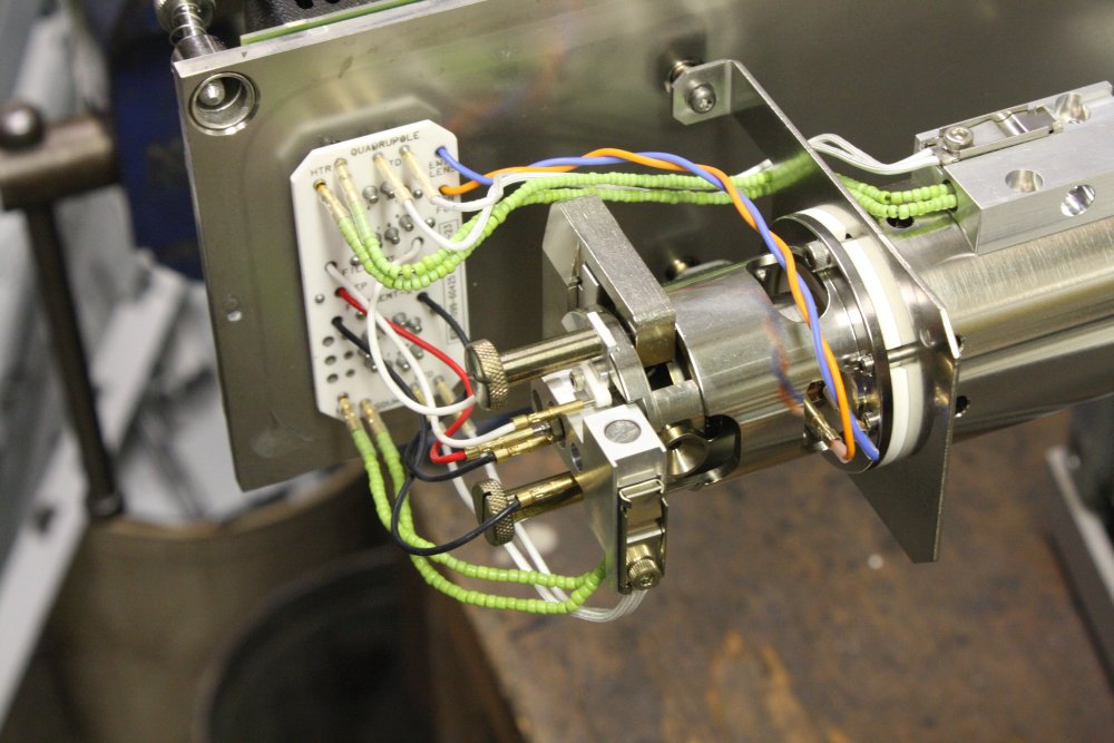 |
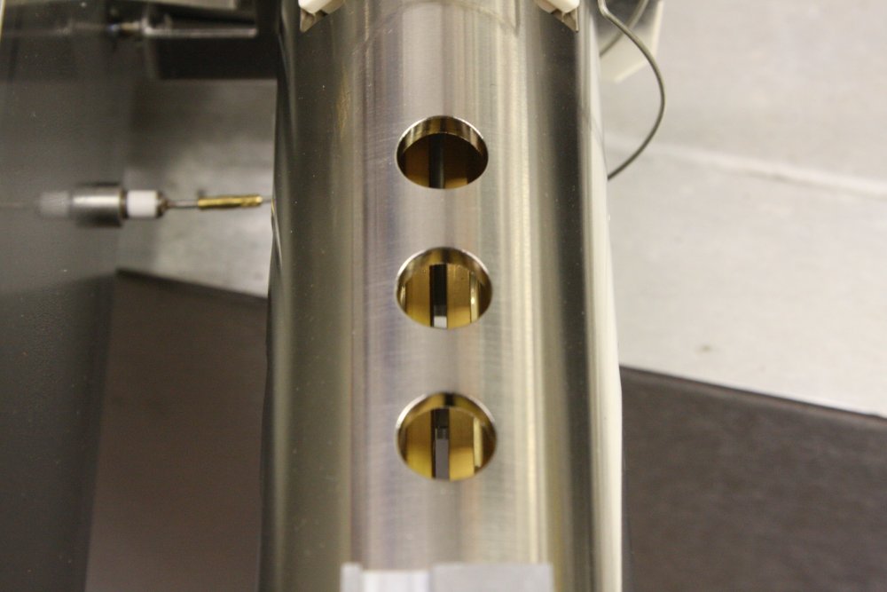 |
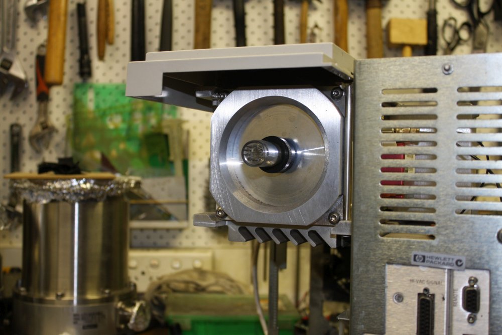 |
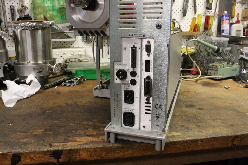 |
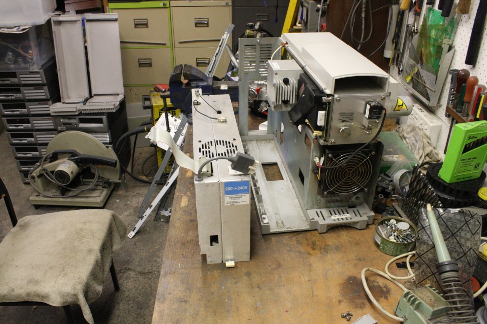 |
1, 2. More of the Jewel. Several interesting points apparent. For one thing it's constructed so the entire quadrupole assembly can be removed easily. That would be for cleaning, probably a fairly frequent necessity as it gets contaminated by sample gases passed through, pump oil film, etc. It goes without saying that this is a no-touch zone, to be handled only with special gloves (eg nitrile rubber or lint-free cloth), taking care to not drop body particulates (skin flakes, sweat, hairs, etc) onto it. It should never be left open for longer than absolutely necessary.
Wires in vacuum are a bit tricky. The insulation material must be something that doesn't outgass. So PVC is completely out of the question. The flexible insulation seen here may be something like Teflon. But that can only be used on wires carrying very little current, since in a vacuum there's nothing to carry away heat. A 'warm' wire will rapidly heat up, till it's hot enough to radiate all the resistive heating power in infrared. Hot enough to degrade any organic insulation. Which is why the two pairs of wires to heater blocks are insulated with glass beads. They don't mind getting hot, and don't outgas when they are hot.
'Circuit boards' in vacuum are also problematic, as the usual materials like fiberglass are porous, and outgas. Also there's a need to be able to see and clean off any surface contaminants. That's why the connector adapter board here is made of a white ceramic, probably Alumina.
Then there's the actual quadrupole rods. In most RGAs these are four parallel cylindrical polished steel rods, which doesn't result in much deviation from the mathematical theory. Theory ideally assumes their shape to be parabolic, since that matches the natural electrostatic field lines shape. But when you don't care about manufacturing cost? Why then you make these rods a precision parabolic profile (on the inside, you can only see their flat rear side here.) And gold plate them, because why not? And why not put neutral grounded ones in between the four active rods, again because who cares about doubling the number of expensive gold-plated precision machined rods?
I love it. Even if I can never get it working.
3. A triode vacuum pressure sensor, mounted on the end of the chamber. Actually this was missing when I first saw the unit sitting in the outside junk heap. Turns out my friend had souvenired it a while before. But gave it to me me when he realised I really wanted to try getting this RGA working. One of the several major obstacles to which, is the missing sensor driver for this. Not yet sure if it might be one of the rear panel connectors.
4. All interface and power connectors in one place. The one really odd connector's mate will return; it's still attached to the oil diffusion pump that will eventually be reunited with the unit. Unfortunately the PC that was used to control this is likely long gone, together with the drive software and PC HP-IB card. Initial reports are it was probably thrown out by the department that tossed this. Though enquiries continue.
4. Another surprise is how easily the electronics pack comes out. One screw and a plastic locking strip to slide out. I was eager to see inside these. What condition are they?
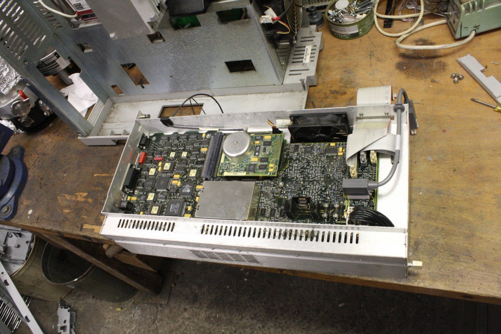 |
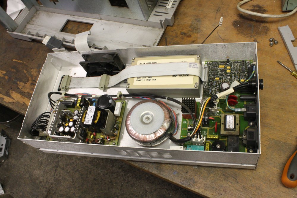 |
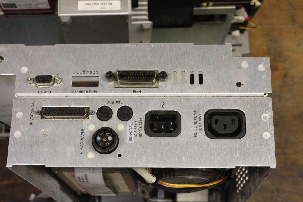 |
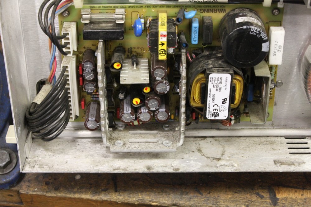 |
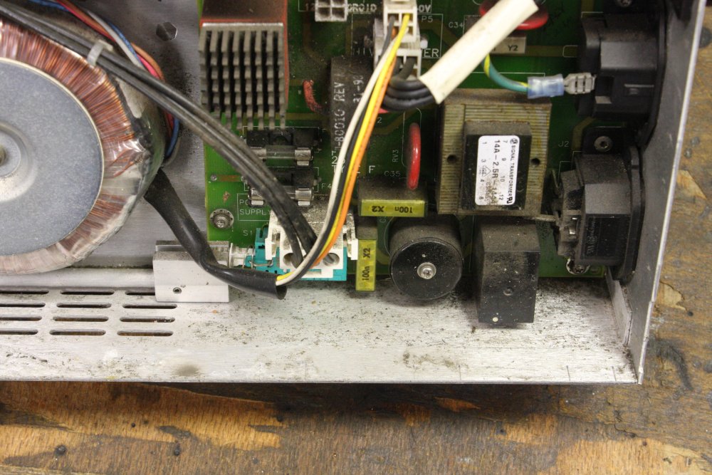 |
1 - 5. Unfortunately the answer is "not very good." The outer case top was in two parts, letting in rain along the join line. Which then dripped down through the fan opening onto these boards. So there's a lot of water staining and wet dust dribbles.
But not hopeless. I've seen worse, and been able to get it working. So long as electronics isn't powered up when wet, or left damp for long periods, or exposed to salty water, it tends to be recoverable. Rainwater is quite clean.
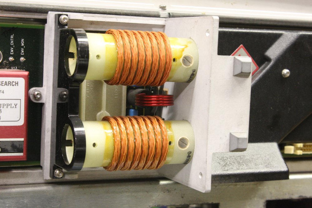 |
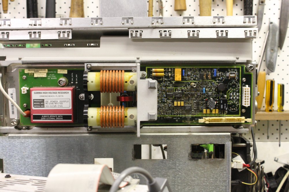 |
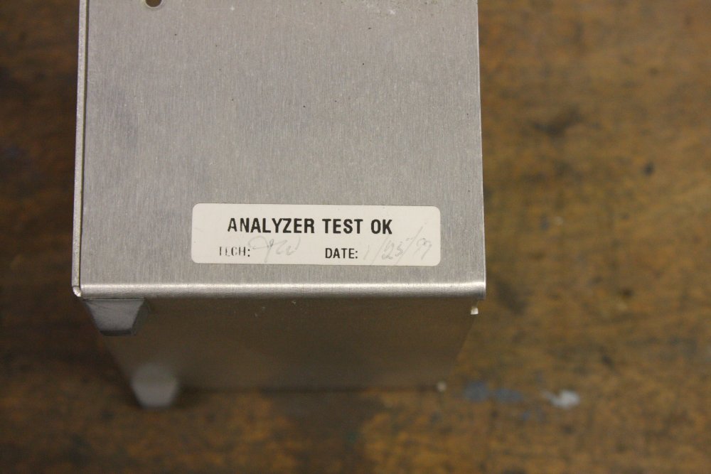 |
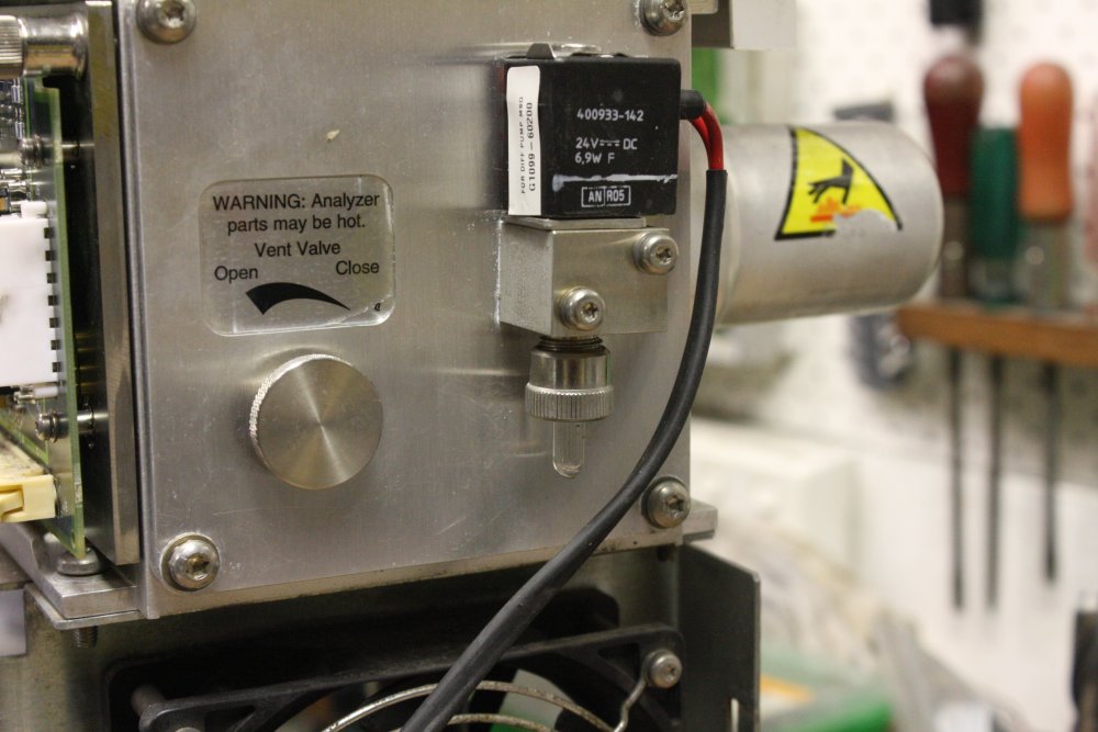 |
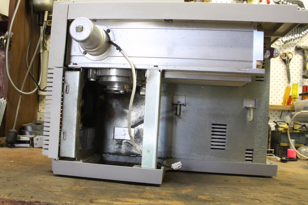 |
1, 2. These coils are the transformer generating the differential signal for the quadrupole electrodes. It's an unusual topology, and a bit counter-intuitive until you see how it works. The small red coil with 4 turns is the primary, driving the two coils on formers, wound of Litz wire and spaced to reduce inter-winding capacitance.
But, the primary and secondaries are at 90° to each other, how does that work?
Well, the two secondaries contain large ferrite adjustable slugs, making the space there have a far higher magnetic permeability than air. The result is that most of the magnetic field from the primary concentrates into a loop on one side, that happens to pass through the secondary coils. The slugs are adjusted to achieve the desired amount of field concentration (output coil power), and balance between the secondaries (equalizing the signal levels.) By the topology the two output signals are opposite polarity to each other.
3. So, this machine was made in 1999. And tossed out as obsolete sometime in 2014-15 according to a calibration sticker. It's still possible I may find out from the original source what the reason was. I'm guessing something along the lines of 'got new model' or even 'became sick of the old Microsoft Windows version the PC used.' Or perhaps because Hewlett Packard no longer exists as such, but became a company that keeps changing it's name (Agilent, Siglint, whatever.) Maybe this machine went out of product support? Lifetime just 14 or 15 years, for something that cost... Hmmm... ebay says the current cost for second hand ones is in the US$15K to $20K range. I shudder to think what the cost was new, in 1999.
Anyway, I don't care. It's my toy now.
Also it's interesting to search for this machine in US ebay. There are various components for sale, and sellers often take lots of photos. So I don't need to take mine apart to see what the parts look like, thus avoiding contaminating mine. Let them contaminate theirs.
4. At first I thought these were a manual (screw) vacuum chamber bleed valve, and a solenoid bleed valve. Wrong... the solenoid is a calibration device. That tiny glass vial contains a liquid that allows a reference trace mix of volatiles into the chamber when the valve is actuated. It appears to be still full.
5. Where the oil diffusion pump was, and will be again. It turns out the diff-pump is missing because my friend had already scavenged it off the machine a while before. And he doesn't mind donating it back to this machine, now we know what it is. Also now I know that cylindrical thing at top left is a gas capillary inlet regulator. The loose plug goes to the mating gas chromatography system.
Well, it's a beautiful and very impressive machine. It didn't take any work at all to find a hardware manual (7.5MB) for this. No schematics unfortunately. Tracking down the early version software may be one of the biggest hurdles. Another being the water ingress.
Restoring this to working will be an odyssey in itself, if it's even possible. Probably harder to get working than the ASI RGA.
For now I'm just storing it away, in a clean environment and with the vacuum chamber sealed up. Not going to touch it again for a while. At least not till the ASI RGA is either working or definitely irrepairable.
ToDo:
- Recover the oil-diff pump, seal and clamp, and cable with special plug, get correct oil and fill, install. Also suitable roughing pump.
- Find the software pack, install in suitable PC. Also needs correct HP-IB card.
- Clean all PCBs, bake out.
- Power up, see if it self tests.
- ... much more...
Leybold Vernier Valve Repair
20170207
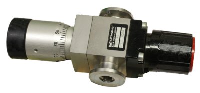 Most of the vacuum plumbing I'd been given was remarkably clean. Except for one valve, a Leybold model 283 41. "Manual valve with vernier adjustment".
This one was full of some yellowish deposit. Needed to be cleaned.
(Always treat deposits in vacuum gear as if they were poisonous!)
Fortunately no metal corrosion, and the deposit was soluble in water & IPA. It cleaned up nicely. One dead O-ring, replaced.
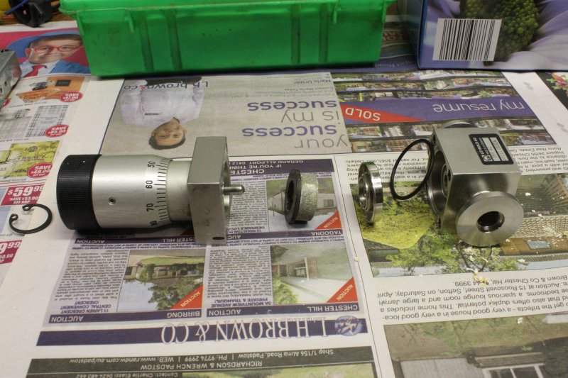 |
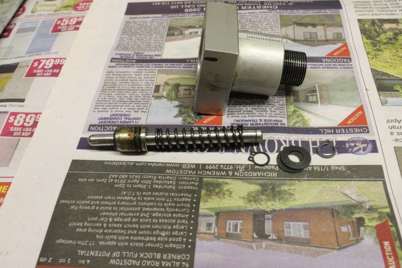 |
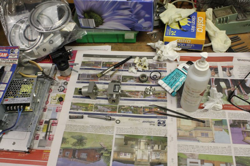 |
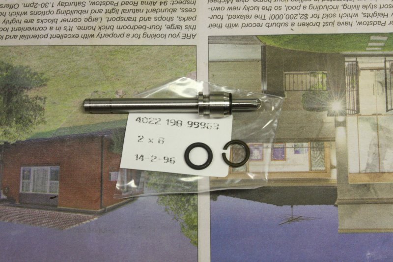 |
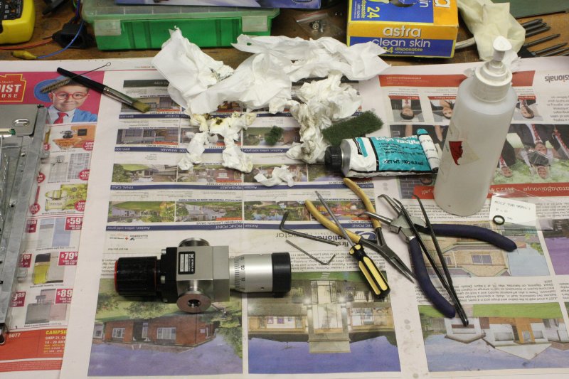 |
LCD Monitor Ceiling Mounts
20170208 - 20170214This was more 'cleanup.' A box of bits for a project to hang two hacked LCD monitors from ceiling rails in the lab. The box had been sitting around on the floor for a couple of months, and the best way to get rid of it was to actually complete the project. So I spent a few days on this, between other things. It's written up separately, see Hang Them High.
Palm Jungle Walk
20170209Speaking of odyssey, a friend of mine in the USA lucked onto a cheap airfare deal, and suddenly told me he was coming to Sydney for a week, leaving USA in a couple of days. He'd never been to Oz before, did I have some tourist advice? Ha ha... he got detailed Sydney Highlights walking directions. Also, we arranged to do a day walk in Royal National Park, which has nice Sydney coastal scenery.
 |
 |
 |
 |
 |

Avoidance Syndrome
20170211
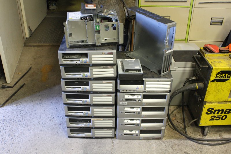 |
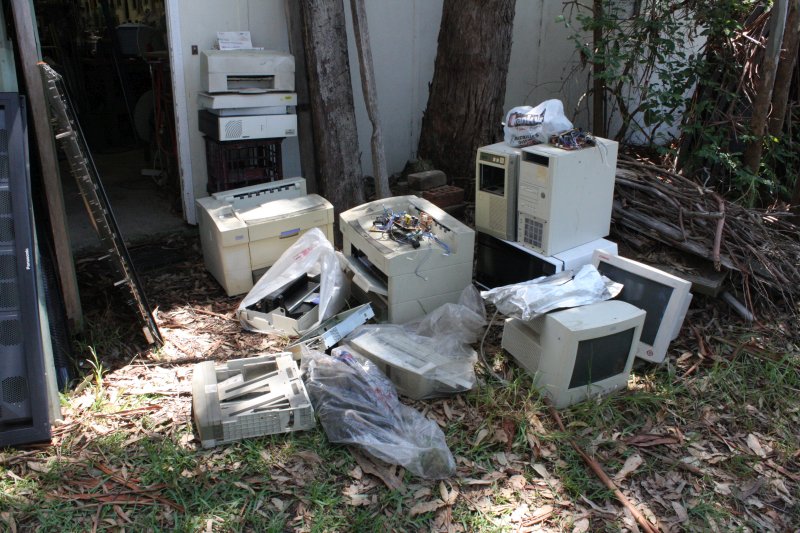 |
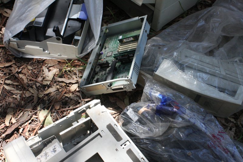 |
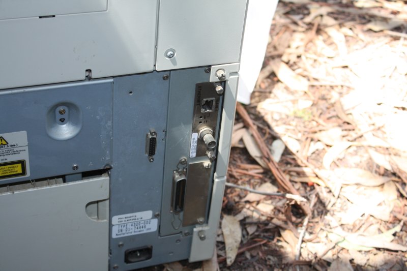 |
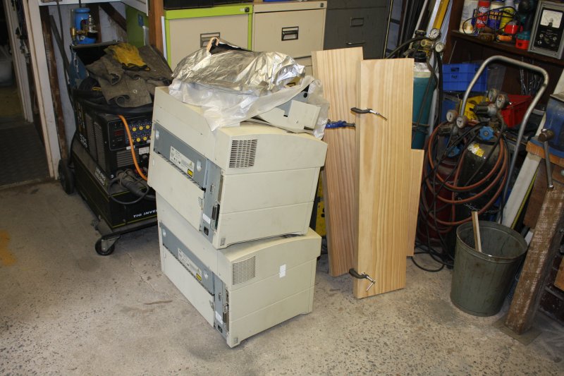 |
1. Also piled up in the workshop, these 13 Desktop PCs. I'd recently accepted them for free thinking they were complete, but they turned out to be missing hard disks. I have a background project that will require a bank of PCs, that don't have to be anything special but would ideally be all the same. There's a possibility I may be given a larger stack of complete (and better) all-same PCs soonish, but till that happens, better to hang onto these. However they definitely have to be evicted from the workshop, now! To where?
The upstairs storage area hasn't had a cull for a while. It badly needs it. Except... urrgh... there's something there I don't even want to think about, but ... it... those... should go. Painful memories attached.
My ex-wife was a student in first year university in Phnom Phen, Cambodia, when the Khmer Rouge overran the city. She and most members of her family were force-marched into the countryside, and endured years of what became known as the Cambodian Killing Fields. It's a long story full of starvation, horror and death, not for this article. When I met her in Australia in 1986 she and her surviving family had been here as refugees for a couple of years. She was a wonderful, kind and caring person. We married in 1986, bought a home (this property) in 1987, and had two children. Paid off the mortgage in 1989. The early years were hard work, but heaven.
Then things began to go weird. I'm an engineer, and knew little of psychology. When she first started acting out of character sometimes I didn't understand. Eventually... after quite a lot of sorrow, the concept of PTSD (Post Traumatic Stress Disorder) was explained to me by a marriage counsellor we were seeing. (I'd previously failed to convince my wife she needed to see a professional, but she agreed to the next best thing, which was seeing a counsellor together.) Prognosis, I was told, especially when the person is adamant there is nothing wrong with them and therefore they don't need any help, is not good.
Years passed. I'd decided with two young children, there was nothing to be done but to try and weather the gales, when they came. After a while things would be calm again, though never ideal. By around 1997 the children definitely needed a bigger house than the little (but nice) old weatherboard cottage. Decision time — either give up and leave, or commit to building a big new house (with an unstable partner.) The kids definitely did not want to stay with their mum. (Daughter's description: "my psycho mum.") Maybe having a nice new house would help my wife? So, a new house and mortgage.
That I'd at last get a decent sized workshop at the end of the process was definitely a factor. But mainly, it was for the kids. The dramas of a woman's mind unhinged thanks to the USA's secret Cambodian bombing campaign, and the resulting blowback continued. I never blamed her, but it was heartbreaking to endure. Little sad events, sometimes really big, scary events, the calm times between gradually became scarcer.
Here's one small example. I forget what year it was exactly. 2003 or 4?
The new house had an upstairs common room. One of the tables there was used for shared computer stuff - printer, scanner, photocopier, etc. Some years before then I'd had a very nice Panasonic A4 laser printer, but it had become old and died. Since then I'd only had small ink jet printers, and they are not very satisfactory. I really wanted another laser printer, but we were short of cash due to mortgage payments (our new house, plus two investment properties.)
By good luck, a friend invited me to help clear stuff from a building his employer was vacating, as the developer wanted to gut it to build appartments. All of the many tenants had been given short notice. A lot of them just abandoned stuff there. I found not one, but THREE identical very good Hewlett Packard A3 networked laser printers left behind. One even with the manuals, drivers CD, and a recent test print (perfect) sitting on top. Someone was being very nice.
Great! A3 sheet size and networked, what a fantastic windfall. Of course it can print A4 too. The second unit apeared intact but a bit dusty, the third was among junk and had a broken lid hold-down plastic latch. ie not working, but probably functional internal modules. Three units... One plus plentiful spares! However they were very heavy and way up in the building, and the lifts had been shut off. It was a major effort carrying them down multiple flights of stairs. Worth it!
A few days after I got them home, I'd cleaned the best, known working one, carried it upstairs in the house, and set it up on the shared computer stuff table. Tomorrow's job would be to install the network drivers on the various household PCs, then show everyone how to use it. Looking forward to having it online.
That evening I was in town for something, eating at a favorite cheap diner (Tamana's Indian) when my wife phoned me. (I'd only recently bought my first cell phone, a cheap Nokia mobile.) Her, angrily: "The printer is broken." Me: "huh? It's not plugged in yet, what do you mean broken?" "It's on the floor, broken."
She seemed to be angry with me for something. This is not unusual, general persistent rage is part of her PTSD syndrome, and there's usually no cause but her own imaginings. In this case the confusing part for me was the bit about the printer being on the floor. Sorting out which printer, why it was on the floor, and what she meant by 'broken' took a while. It turned out she'd decided she didn't like the look of it on the table (no reason given, and that's where other computer stuff is.) So she'd slid it to the edge of the table, apparently imagining she was going to lift it down and to the floor. Did I mention it's very heavy? I mean very — I'm strong, and carrying these large things was a strain for me. She'd have no hope of lifting it. Somehow the act of pushing a heavy object across a table hadn't informed her it was heavy. So, it fell from table height to the floor. Luckily didn't crush her foot or something, but it did make a deep gouge in the nice new polished hardwood parquetry floor. Also of course completely destroyed the printer. Badly warped frame, not repairable. She never even apologised; instead seemed to continue to be angry with me as though it was all my fault. Irrational, on top of destructive, but I was very used to that by now.
So, the salvageable parts from that printer, and the other two have been sitting in my workshop upstairs storage area ever since. In the spot I'd put them down next day, knowing I wouldn't be able to bear touching them again for a long time. They'd taken on the 'essence of tragedy', summing up all the years of heartbreak and pain and disappointment that our marriage became. It compounded over further years, with incredible events that I won't relate here because you would not believe them. An exact quote from one of the police involved: "We've never seen anything like this before!" They were helping me, but the bizarre situation and astonishing legal catch-22 SNAFUs defeated them too.
Pic 2 is stuff sitting outside the workshop on 20170211, waiting their turn to be rendered down to parts. The two intact printers are among it, plus parts from the one that died that day when pushed off a table. Pic 3 is the processor cage, bent since the network card (that was in the empty slot) was one of the things that met the floor first.
Pic 4: One of the remaining two also has a network card. Which is a problem, since it means... I could probably get one of these working, if it hasn't degraded to unrepairable in the years since. Which it probably has.
Result: Pic 5. They are still sitting in my workshop. I need to just bite it, scrap them, and never think of this again. But there's still a strong avoidance syndrome in play here. Instead on 20170215 I stripped down the large office machine that was the other last thing taking up floorspace.
Rackmounting the RGA
20170216OK, the junk is 90% cleared, now what? Remember the aim of the junk clearout was to have space to make the wall vent. Which will include some welding and grinding; things I don't like to do while there is delicate electronics sitting around. But wait... there is still the Anglo Scientific RGA assembly sitting on the floor. While making the LCD ceiling mounts (welding and grinding) I just covered the RGA with cardboard and cloth, but I really can't keep risking damage to it. The RGA is far more important than the wall vent, so deal with the RGA first.
Which means putting this...into this.
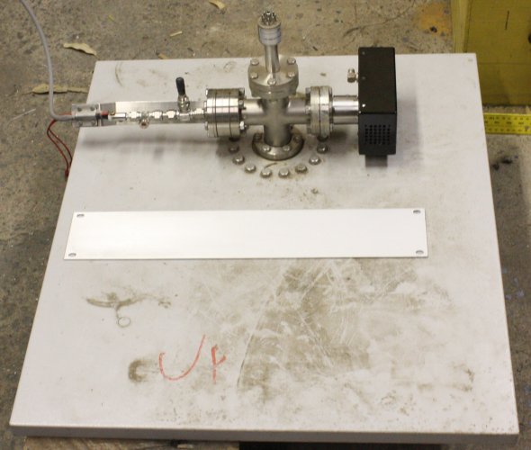 |
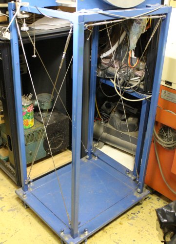 |
Needless to say, it doesn't fit as it is.
However I do this, I want it adaptable. No special purpose holes drilled into the vacuum chamber stand! No effort put into something that is too specific, and may turn out to be wrong later. Also preferably, a solution that can be used for other things too. Other things like 19" instruments.
Looks like the best way to do this, is to fit the vacuum chamber stand with 19" rack mounting rails, and then convert the RGA head into a 19" rackmountable module. Which will be a bit of work, but I do like this idea. Too bad those who originally constructed this stand (not me) didn't make any allowance for such an obvious thought. The dimensions are clearly just whatever resulted from ad-hock adaptation to the chamber size. Oh well. I went and bought some aluminium L section.
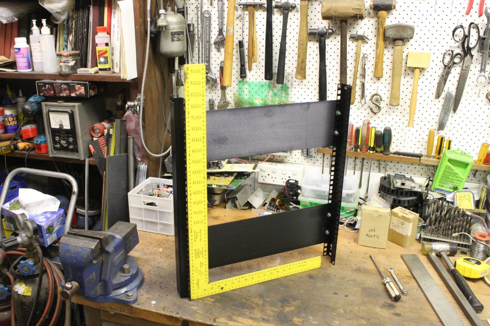 |
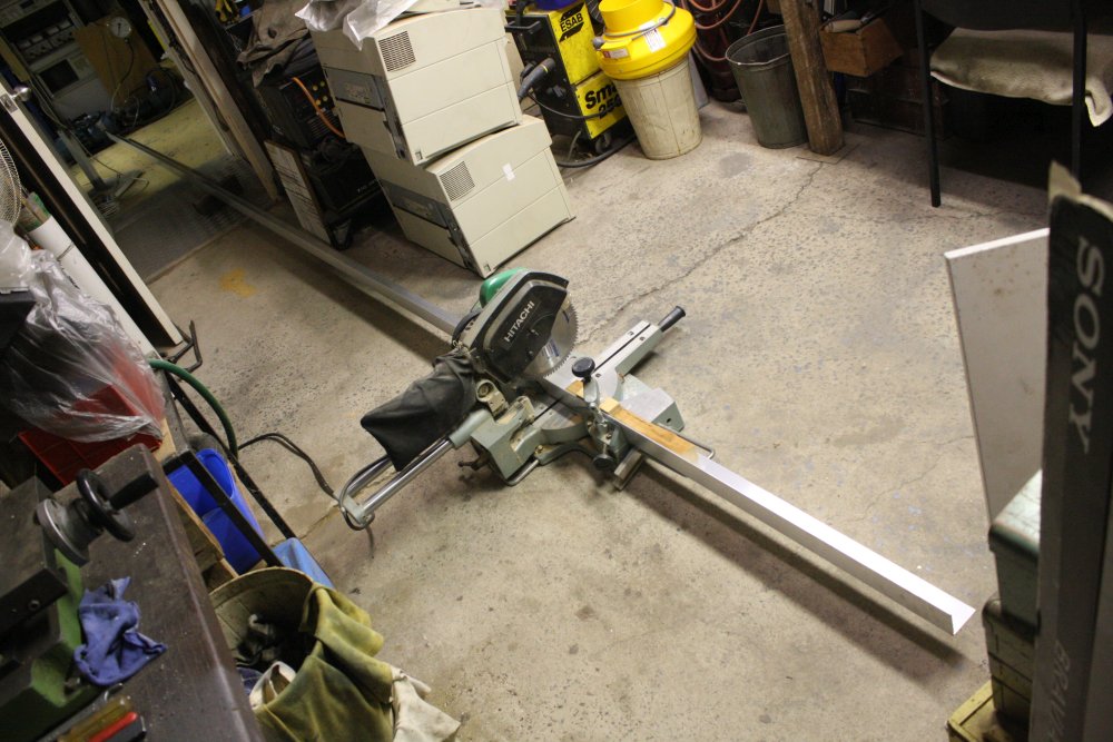 |
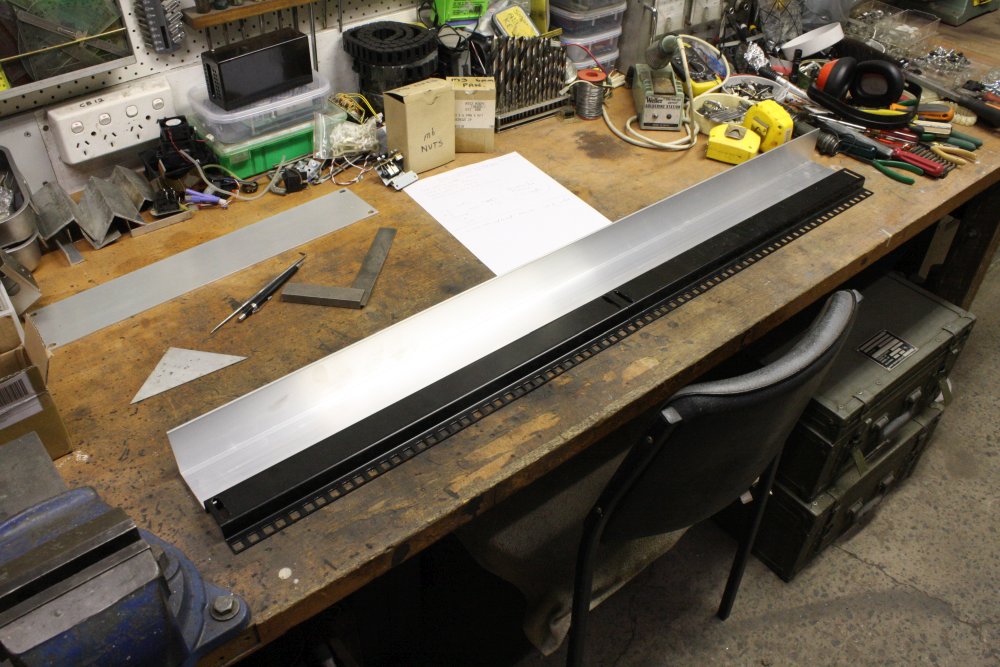 |
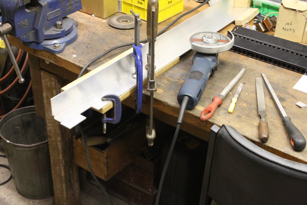 |
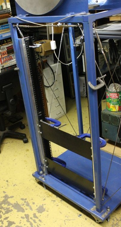 |
1. When making something to fit 19" rack stuff, one needs a 19"-rack-stuff template. That's this thing. A couple of blanking panels fixed to rack side rails, so the rails are square and spaced correctly. Opening width: 450mm, Screw H spacing: 465mm.
2. Nice long piece of aluminium, too big to fit in the room. Getting it inside at all was fun.
Also nerve-wracking to cut something expensive like this. 6.5 meters of 60x60x3mm, $65.87.
3. Cut to match two 535mm rack rails end to end. At the moment I have plenty of these.
4. Some little cutouts to clear parts of the vacuum chamber stand. Quickest way is with an aluminium cutting disk in the grinder, them file smooth.
5. Using the template to clamp the L sections in place to give the correct rackmount spacing. (And measuring and remeasuring, to check.)
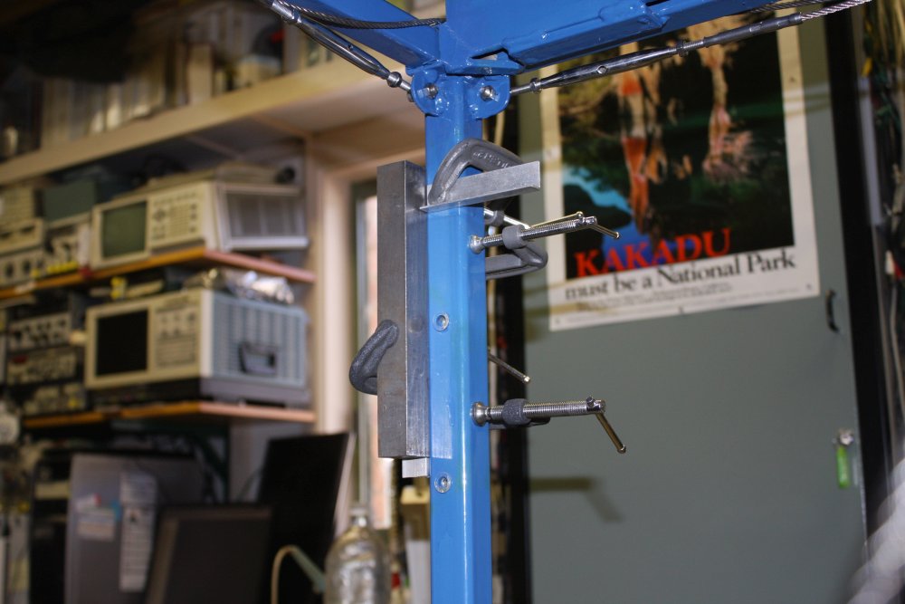 |
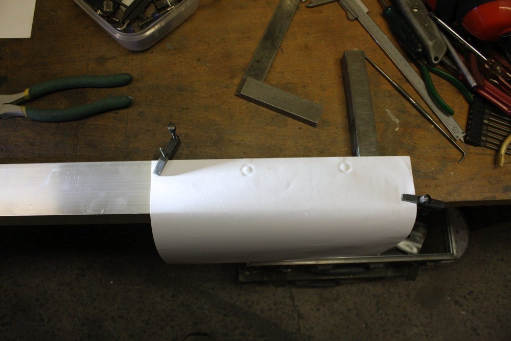 |
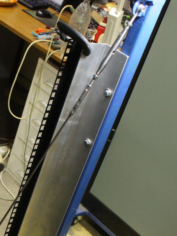 |
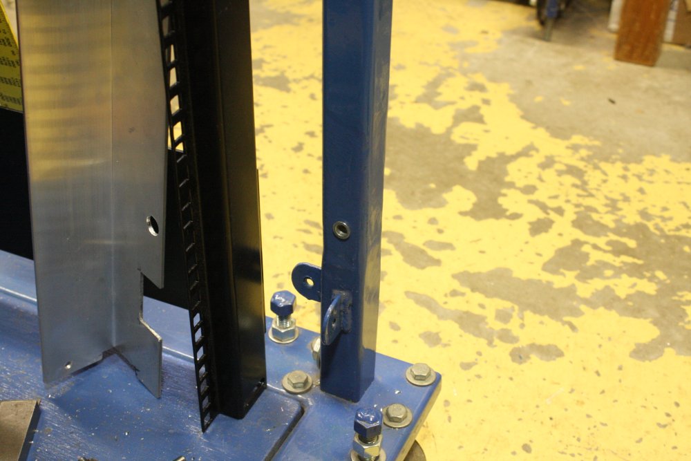 |
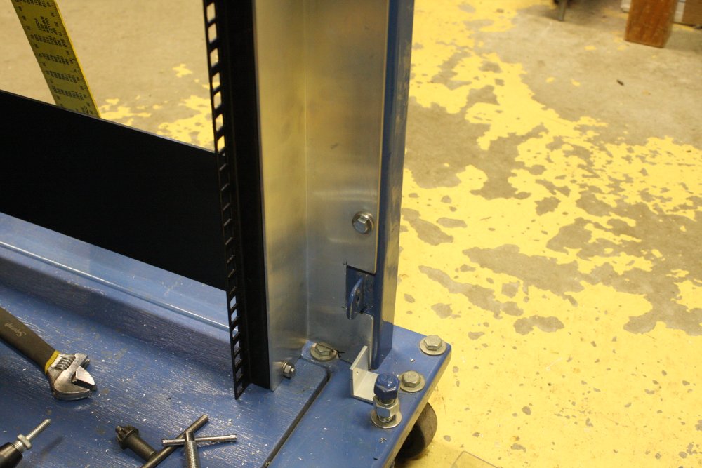 |
1. The frame already had a few nutserts near the top, put in by its previous owner. They are not positioned terribly accurately, and I'm going to use these as fixing points for the rack rails. The best way to get the holes right, is by transferring. Err... but how? The aluminium goes up against these; can't just mark them by hand. The clamped-on bits of metal were pressed against the L-section edges, to align a bit of paper over the nutserts.
2. Using a paper impression transfer. So long as the paper is accurately positioned, it works well. Just press the paper onto the feature with fingers, to make these impressions. Then shine a light obliquely on the paper to see them clearly.
3. Top screws done. But there need to be more.
4, 5. One in the middle, and one down the bottom. So yes, I did drill more holes in the chamber stand. For a general purpose racking system, it's worth it.
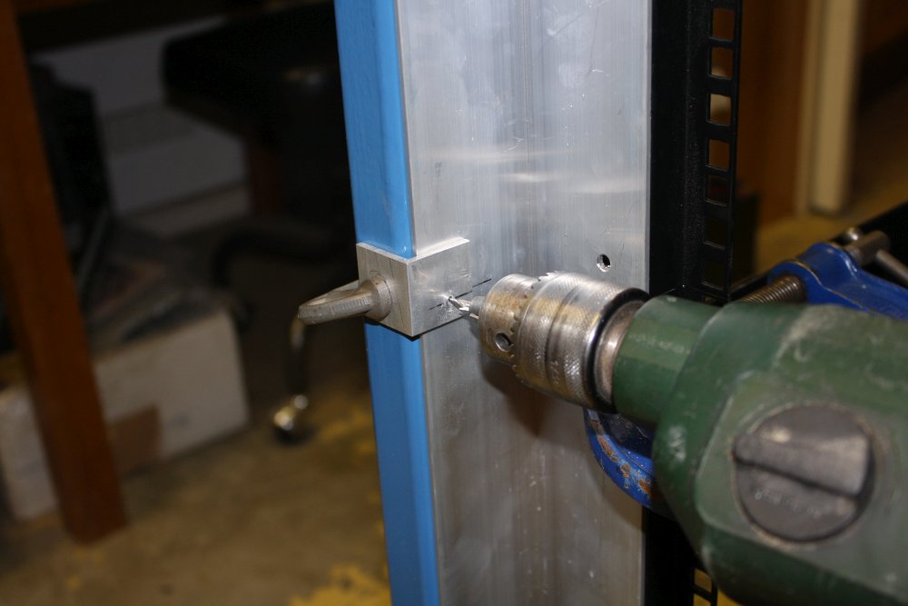 |
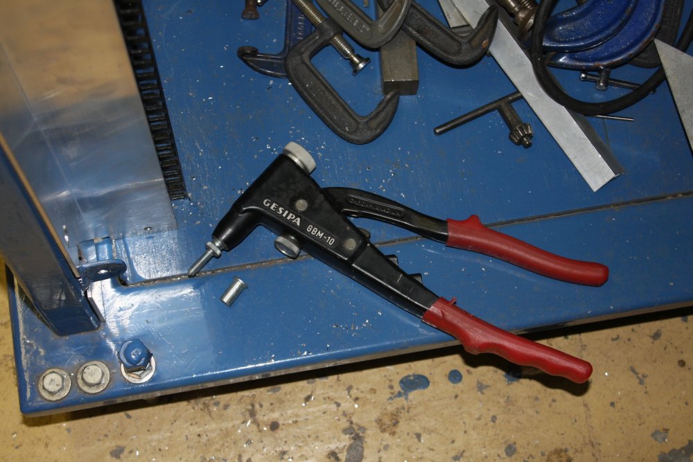 |
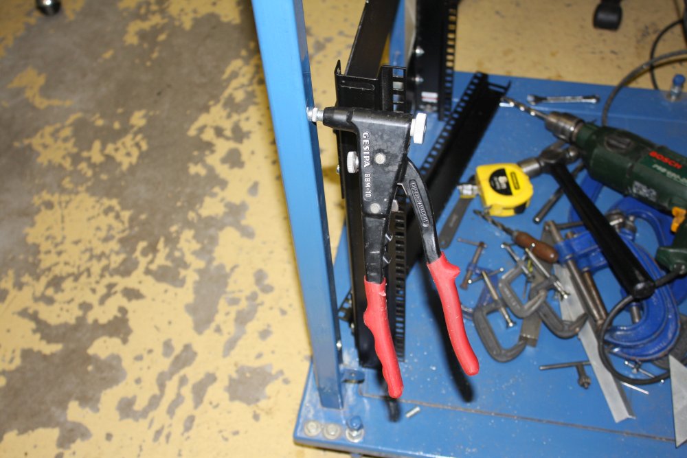 |
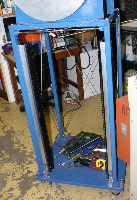 |
1. How to get the holes perfectly placed and lined up. Drill through both with a small drill. The small bracket is to get the hole in the center of the steel post face. Then drill each piece to the size it needs to be.
2, 3. Nutsert and tool. The nutsert is a steel cylinder, outside flange on one end, center section that is just thin walled tube, and thicker other-end section with internal thread. The tool just squishes the tube shorter, which expands the center tube part. "Just"... ha ha. These ones are steel, in a large size that is only supposed to work with aluminium nutserts.
Result: I can only squash them using the absolute limit of my hand strength, both hands, and bruising my palms. Not something I want to do often. I also have a hydraulic hole punch that is a joy to use, but it doesn't have an adapter for these nutserts. Must get or make one.
4. Front rackmount rails, DONE! But of course that's just the start of this.
Shrinking the RGA Decapitated Head
20170219For rackmounting the RGA head, the long plumbing extension off one side of the RGA head really needs to be removed. Anyway I probably won't need the capillary input for most uses, and even if I do it can be reconfigured to not stick out so far. Now is a good time to disassemble it. One more thing safe from accidental damage.
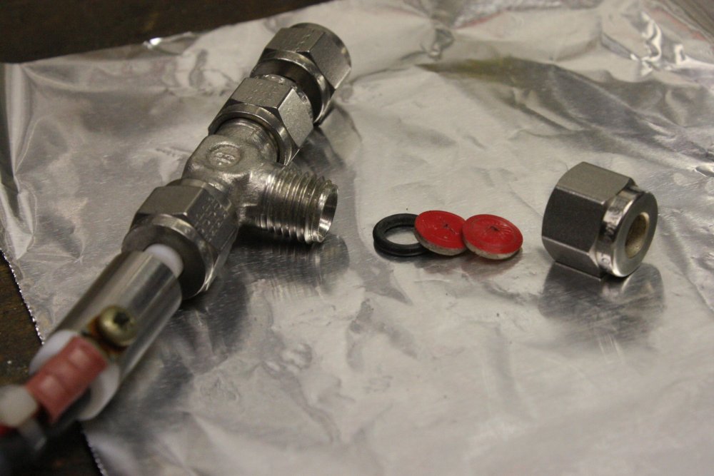 |
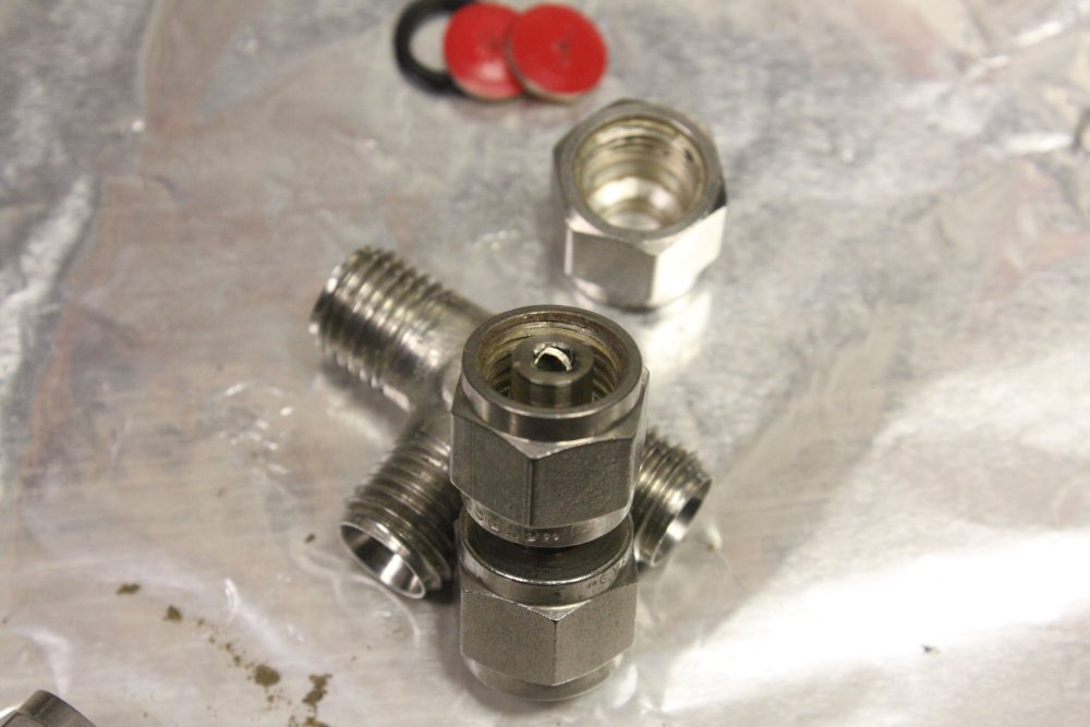 |
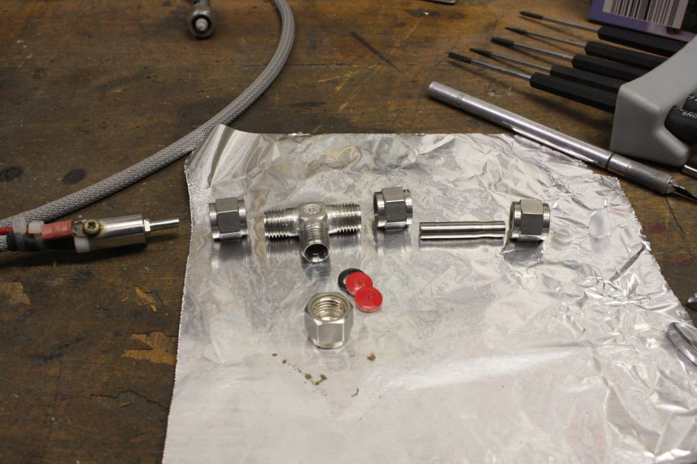 |
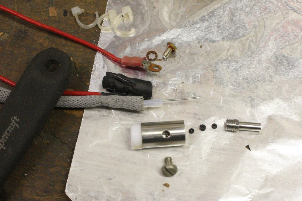 |
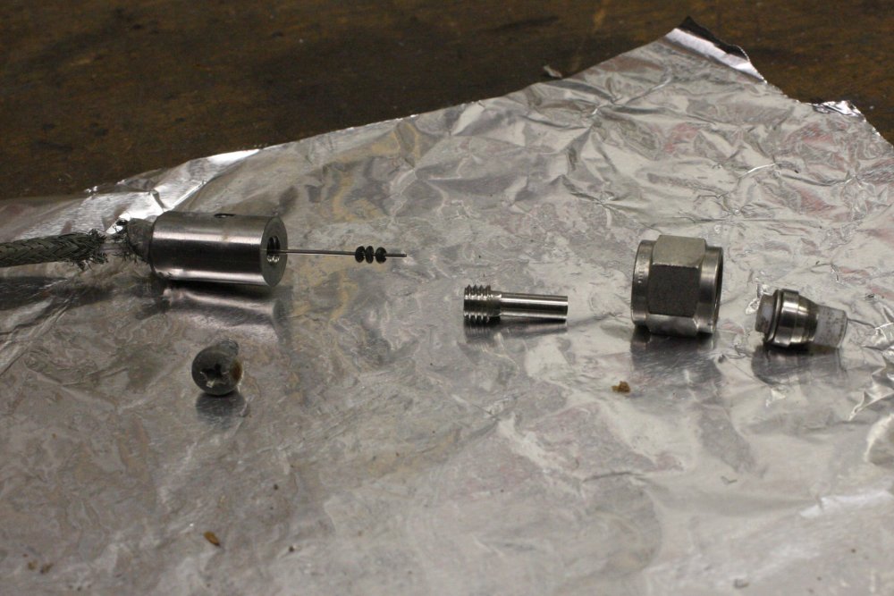 |
1. Ah ha. I'd guessed the red thing is an over-pressure relief, and it is. The two disks are soft rubber with a stiff red layer on one side. There's a fine scalpel cut right through near the middle on both of them.
2. I'm noticing a bit of rough construction here and there. This joiner tube has been cut very roughly, leaving a lot of swarf bits in the end of the tube. I can't believe this is any kind of deliberate micro-baffle or something, since this is at the input to the vernier needle valve. Or maybe it's meant to protect the needle valve? Surely something more repeatable would have been better? I cleaned it up, to a neat edge.
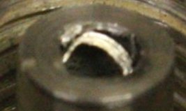 Hmm... To my bare eyes, that rounded piece looked like a ring of stainless steel swarf leftover from cutting the tube. But now I look at this photo, I wonder if it might have been a tiny strip of magnesium or some other reactive metal, intended to capture reactive gasses to keep them out of the RGA?
Too bad I binned all the tiny shavings.
There's also quite a bit of powdery gray-brown dust sticking to the inside of the tubing. Which must be condensed from whatever got through the fine capillary. I wonder if the capillary is fouled like this too? How do you clean a long, really thin stainless capillary?
3. Just a record of the ordering.
4. I'd wondered what these parts were. Expecting something exotic. But in reality they are simple, and now I understand how this system varies gas throughput. The inlet is a long fine stainless steel capillary. This metal piece just makes electrical connection to one end of the capillary, as well as sealing the end to the vacuum plumbing. One wire (with ring-lug) screws to this endpiece, and the capillary is secured in it by another screw. (Lightly, to not flatten the capillary!)
The other wire connects to a copper braid that runs back along the capillary, between an inner and outer insulating sheath. The braid connects to the other end of the capillary.
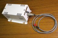 Current applied via this small transformer runs through the stainless capillary, heating it. The temperature changes the gas flow rate. The transformer has three settings: Low, off, high.
This arrangement does require that at one or the other end of the capillary, whatever it connects to has to be electrically isolated. It isn't at the RGA head end.
5. The other end has a similar metal terminator, except here the copper braid is soldered to it. Or was — flexing has broken most of the copper strands. Repairable, though I'm not sure I have any soldering flux that does stainless steel.
In my system I'm unlikely to need this capillary feed, since it's for sampling gas from a relatively high pressure source (atmosphere or higher) to the vacuum in the RGA. In mine I'll mostly be looking at vacuum residuals. So a plain tubing connection and the vernier valve will be adequate. For now the filament components are ziplock bagged, for cleaning and repair later.
The Rest of the RGA Rackmounting
20170220 — 20170223The RGA is quite heavy, and most of the weight is in that turbomolecular pump. Which definitely should be mounted solidly. No unexpected mounting vibration resonances, and also reading the turbo pump manual they mention the mounting must resist at least 1000Nm of torque. I suppose so the pump doesn't rip out and fly across the room if it has a blade crash while running at 56,000rpm.
So mounting the whole thing just by a standard 19" rack facia plate is not on. Also other things in this rack may be heavy and need rear support too. Rear rack mounts required. Though, these don't have to be pretty, and I don't want to use up another four of those rack struts (all I had left.) This one can be plain steel, though it must have screw holes to match the front struts.
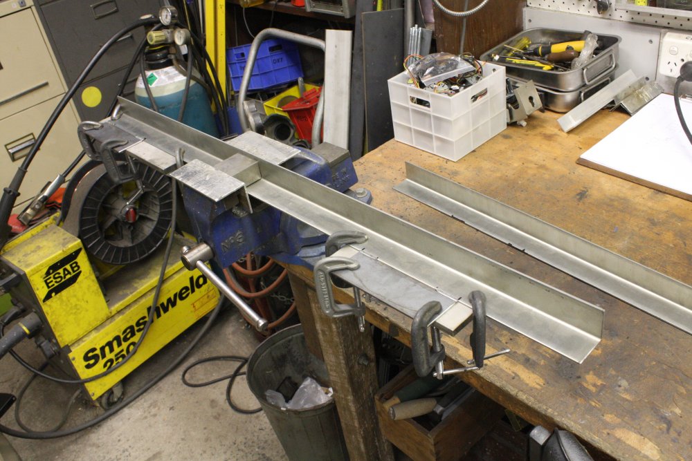 |
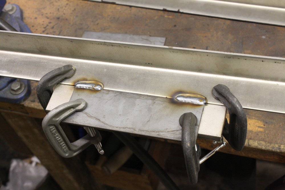 |
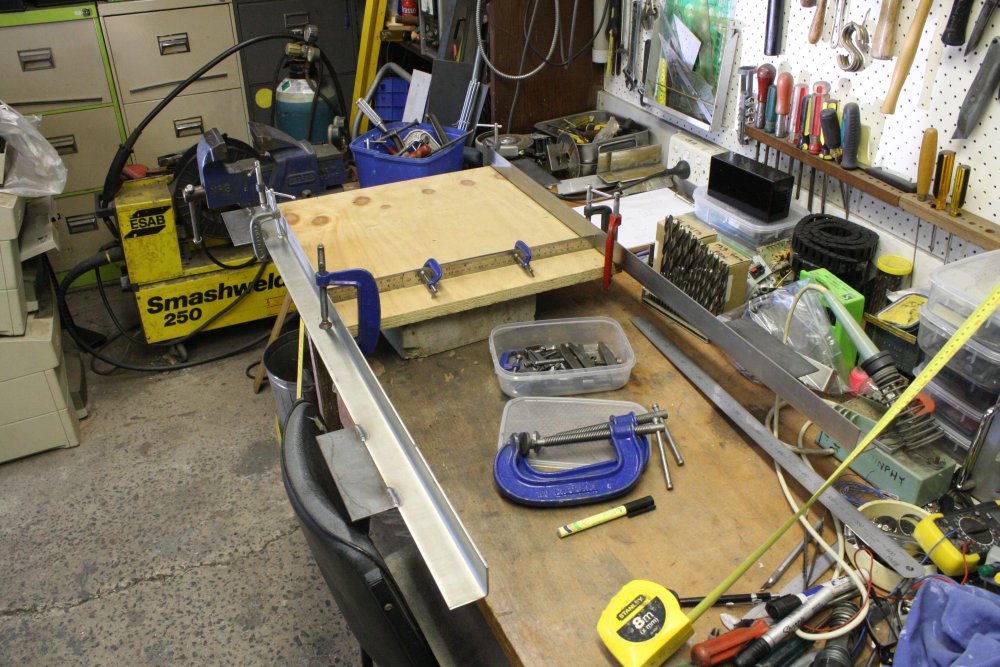 |
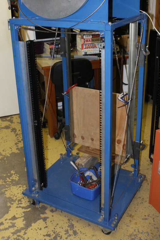 |
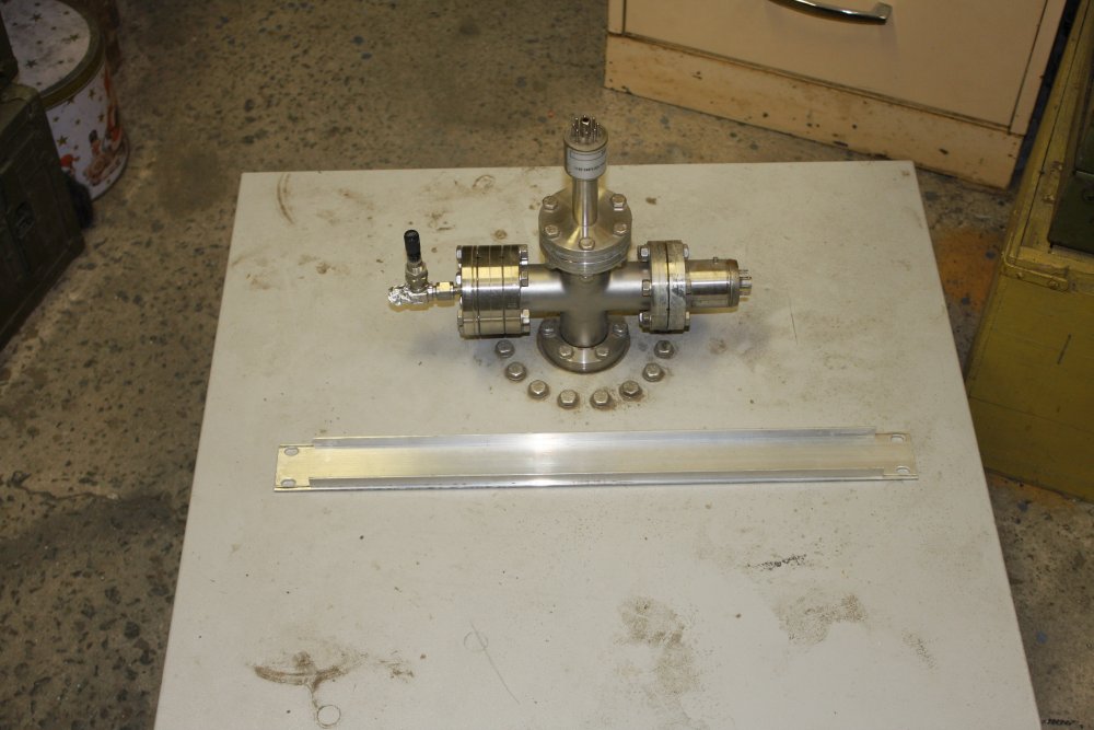 |
1. I had the steel. Here preparing to weld on the mounting tabs.
2. Like so. Edges beveled all the way through before welding, so penetration is complete. No need to run the weld full length and risk warping the steel.
3. Clamping the pair in the correct spacing.
4. The pair clamped into the rear of the stand. More to get the support and clamping in place, for easy adjustment. Note it doesn't need to go all the way to the bottom, because any instrument in the bottom can just sit on the base. But I did want it all the way to the top since I may want to mount electrical, pneumatic, etc connectors there in future. Where they are easily accessible while this thing is up against another rack.
5. Now thinking seriously about where to cut the RGA sheet metal plate. This is the rack facia bracket I will use.
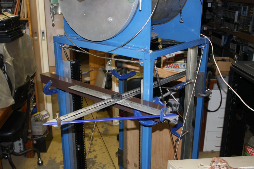 |
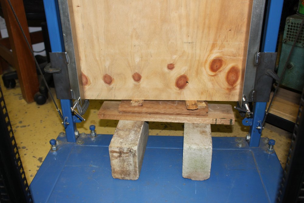 |
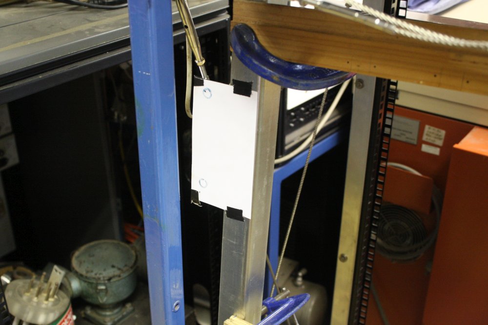 |
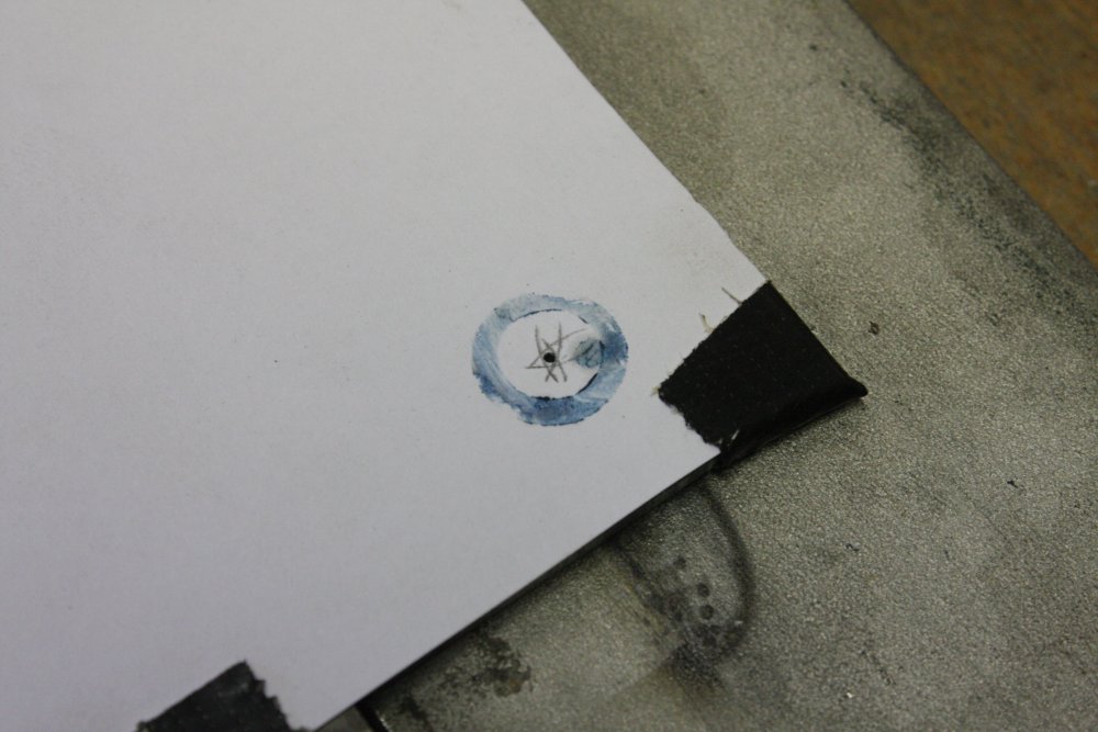 |
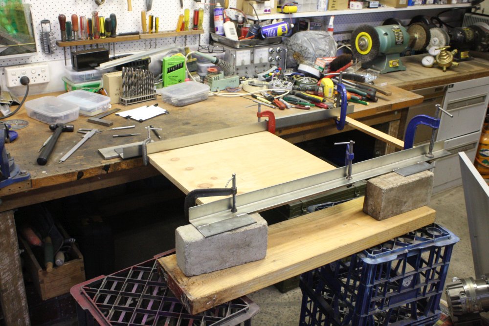 |
1. Never assume existing structures are square. Here ensuring the rear rails are in line with the front ones.
2. Wedges for fine adjustment. Because to move it, all four securing clamps have to be loosened, and trying to get it right while holding it by hand is hopeless.
3. This time used a simpler method to transfer-mark the positions of the existing top nutserts. Bluing rubbed on the nutserts, paper taped on the mounts, then clamping them together.
4. The bluing marks. Compass used to get an accurate centerpunch despite the irregular mark outline.
5. Centerpunching more solidly.
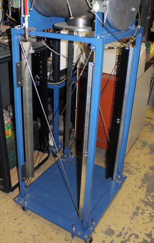 |
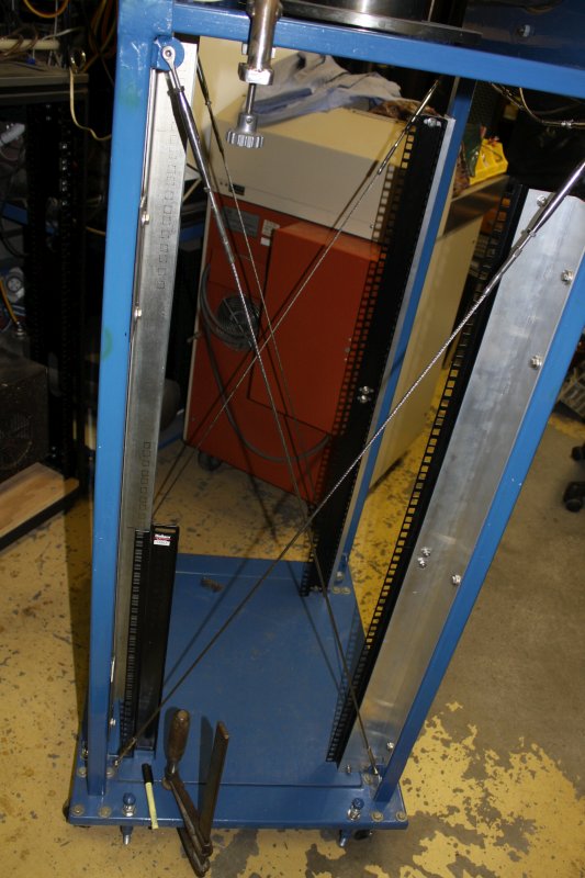 |
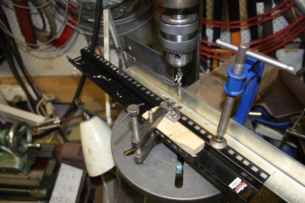 |
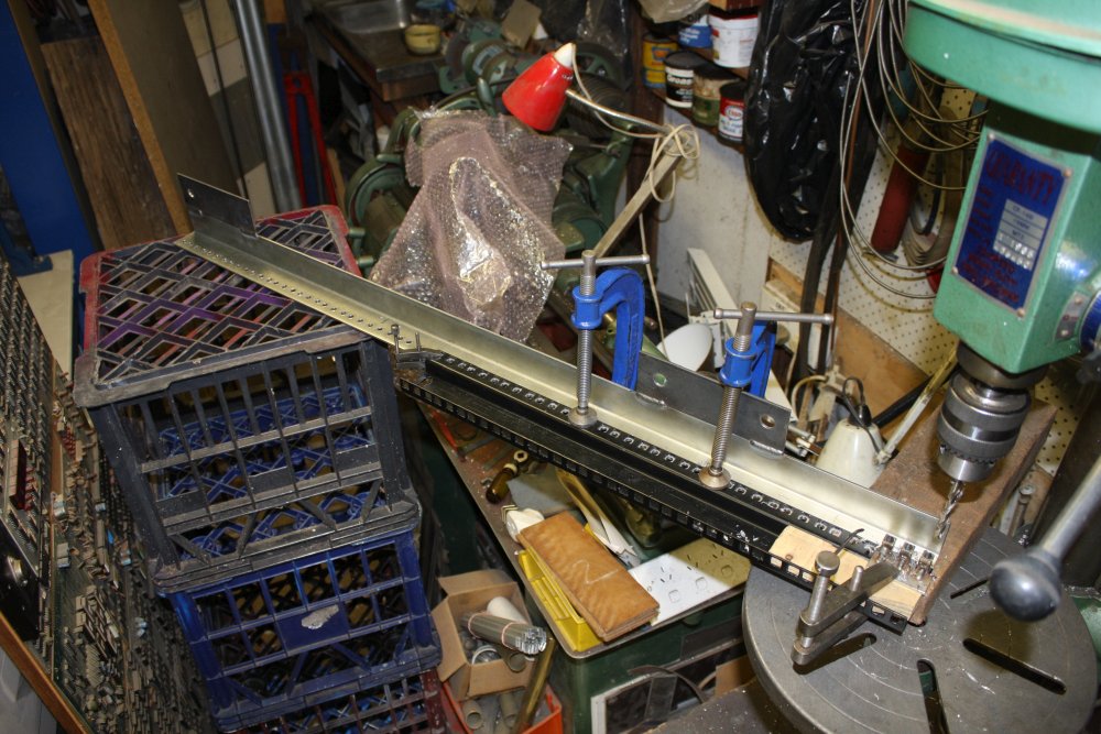 |
1. The rear strut mounting finished. But that's not all...
2. There need to be holes matching all the front rail holes. And they need to be pretty accurate. Here I'm marking them, not to drill to the markings, but to position the drill template I'll be using. Important to get the cycle right — rack rail holes are not evenly spaced, but repeat in a 3-hole unit.
3. The template is one of the actual struts, together with a centering jig I made last time I had to do something like this. Can drill three holes, then move the centering jig. It's a press fit in the strut square holes. Lots of holes to drill, but it goes relatively quickly.
4. Second strut, many holes later... all done.
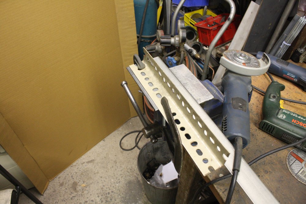 |
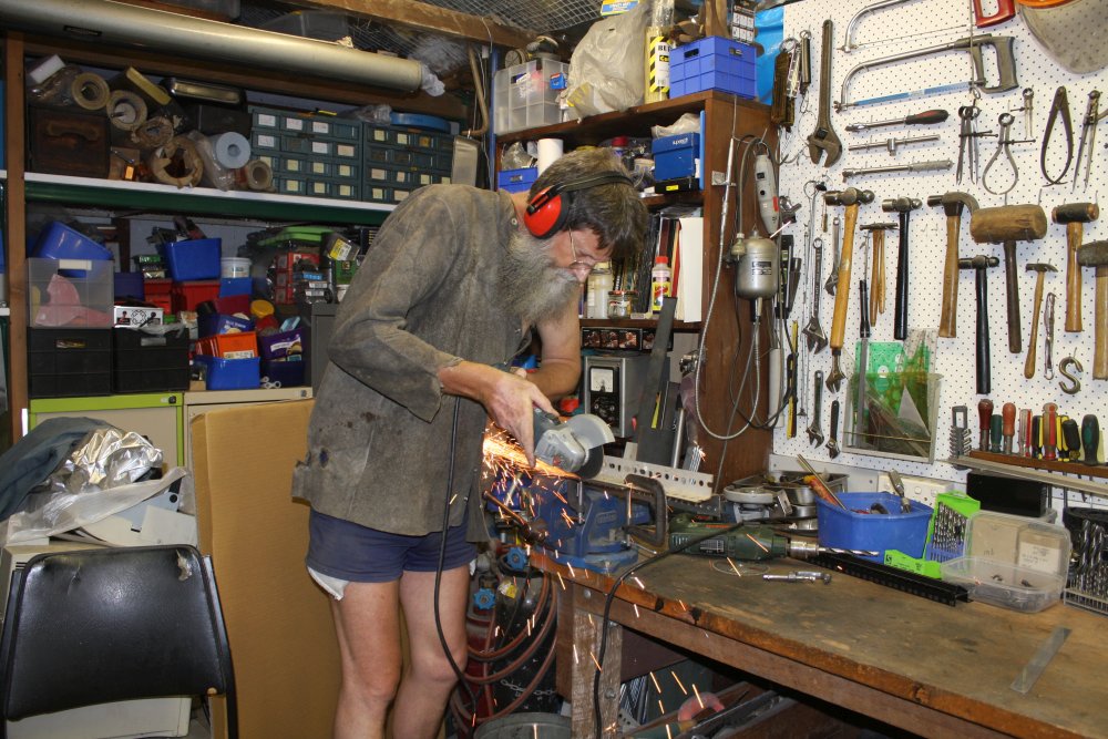 |
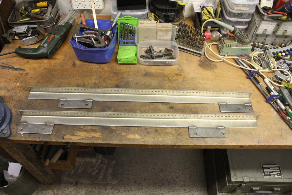 |
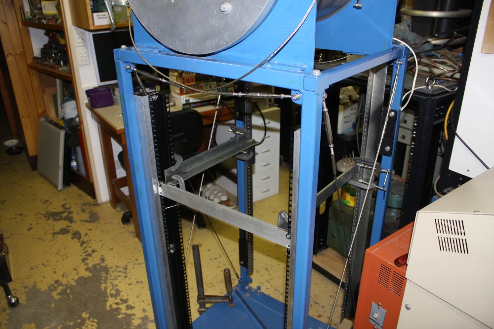 |
1. The tabs stick out a bit, and have to be cut off. (Result of what metal was available, also to allow plenty of adjustment leeway.)
2. This was one of the very hot days in Sydney this summer. Wearing shorts only isn't great when for cutting a neat line you have to direct the grinder sparks-stream at your stomach. In the heat the leather jacket was nearly as bad. So, worn cave-man style, one shoulder bare.
3. Done. Wow, look at all the little holes. Sure glad I didn't have to drill all those! Oh wait...
4. All verticals in place, now adding slide rails for the RGA assembly.
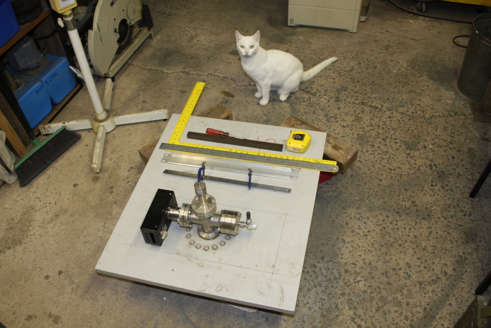 |
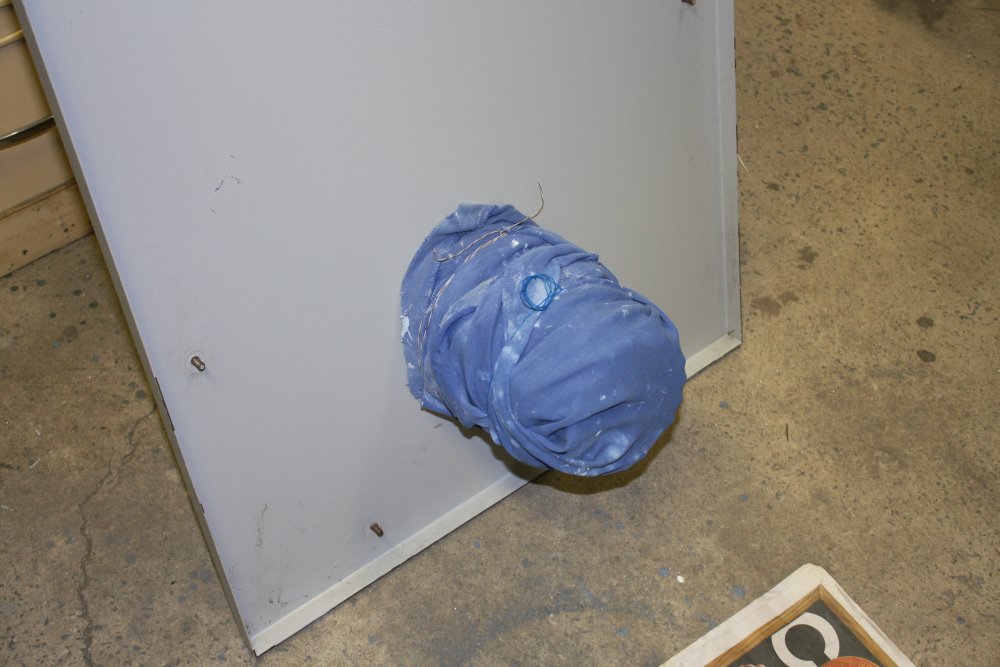 |
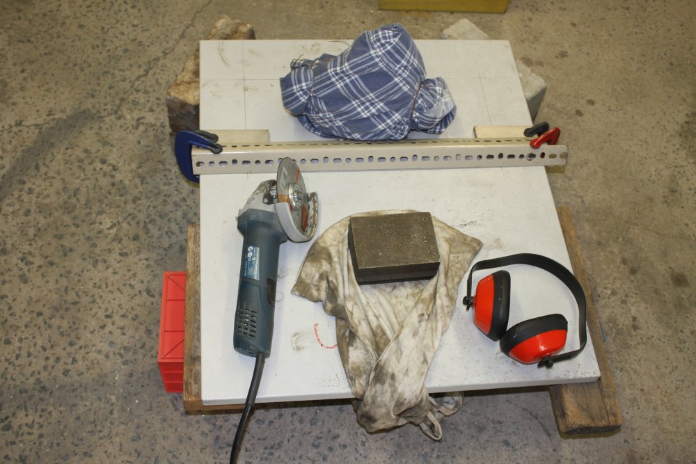 |
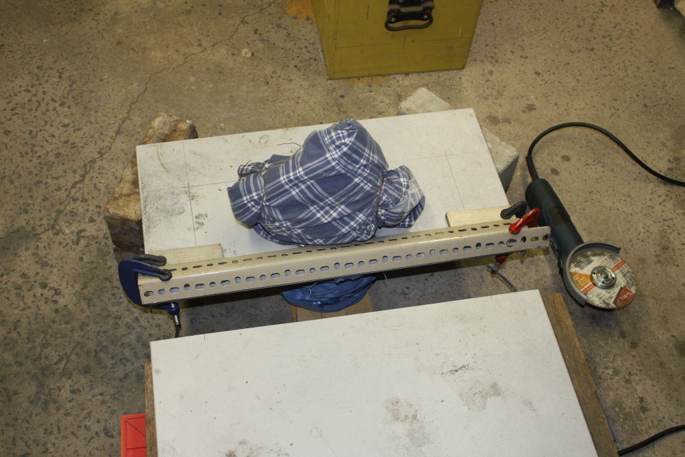 |
 |
1. About to commit. Outline marked. My cat Blanc says "You know you are going to screw this up, don't you?"
2. Protecting the RGA turbo from the coming rain of grinder grit and sparks.
3. With a bit of scrap steel as a grinder-resistant ruler, it's possible to get a very clean cut. Start lightly, running along with only very light sideways pressure against the ruler. It does lose some metal, but you keep the movement even so the wear is even too. Once you have an adequate groove in the metal you are cutting, you can switch to only pressing downwards. Then the ruler is only there to block accidental slips. Which shouldn't happen, but you know...
The block of steel sitting on some cloth is there to suppress vibration in the sheet. Cutting sheet metal with an angle grinder is extremely loud, and I have pity on my neighbors. And my ears, even with muffs. Also the RGA, though with the turbo's mass this kind of accoustic vibration won't have much effect.
4. Cut! It's very quick.
5. 3rd cut done.
 |
 |
 |
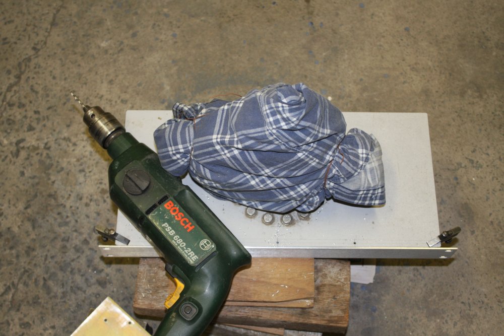 |
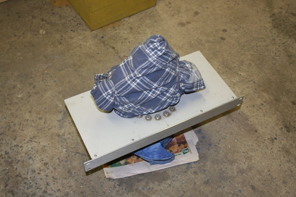 |
1. Done cutting. Oh thank god, no more of that awkward huge panel.
2. The angle grinder leaves a lot of sharp edges. Here cleaning up the edges and corners with small file and sanding block, till the edges feel smooth to the touch.
3. Center punching for screw holes. On a solid backing block, to avoid any shock transmission to the RGA.
4. Through drilling with the rackmount facia in place. It's too thin for tapping threads, so will have to use screws and nuts. Also they will be countersunk heads, but for now I'll use plain cheese-heads.
5. Screwed on. Bah. I should have drilled for 6 screws not 5. So there would not be one right in the middle, very close to the turbo. Like this it's hard to get the nut on that center one. There's always something.
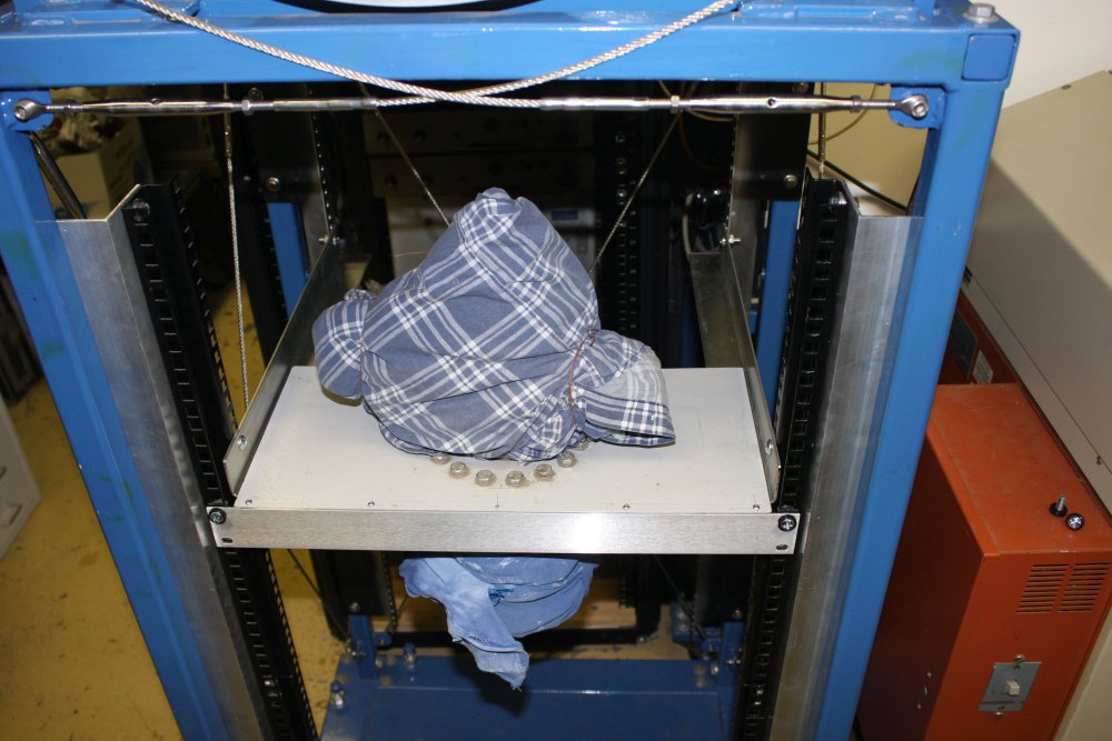 |
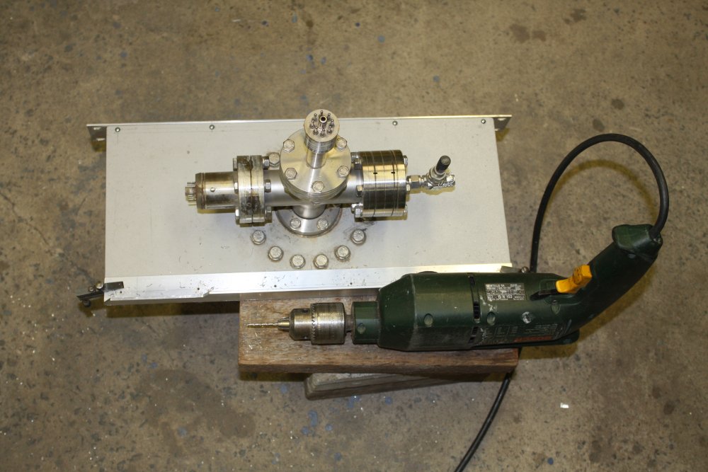 |
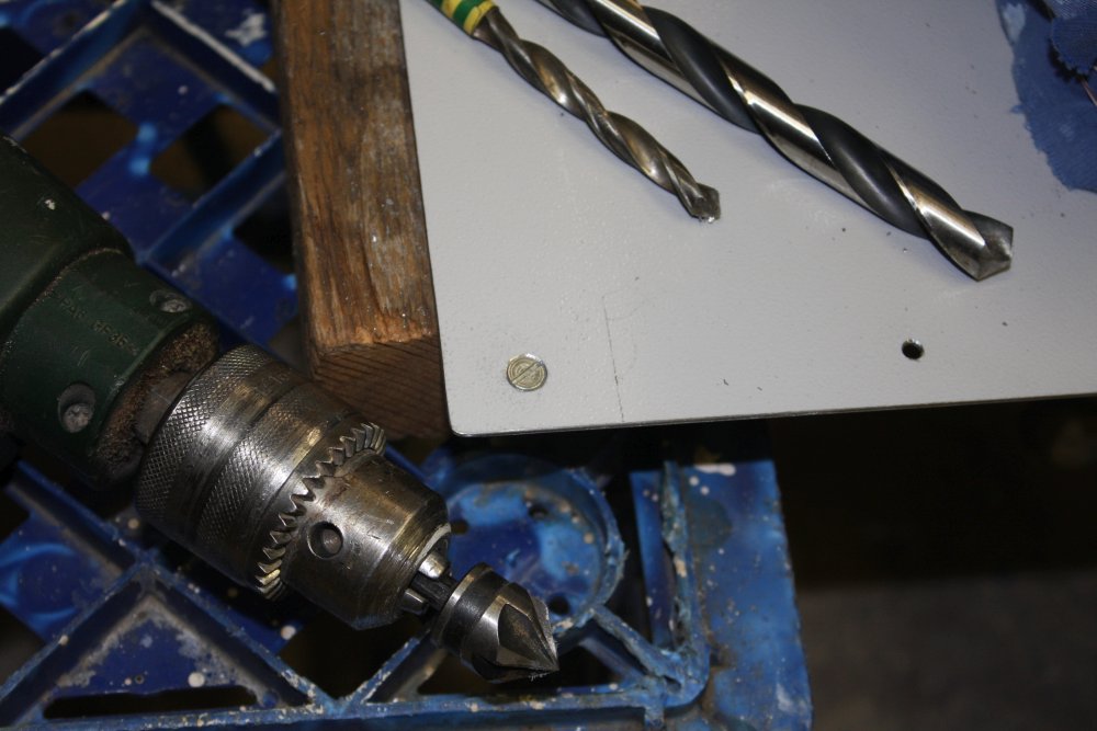 |
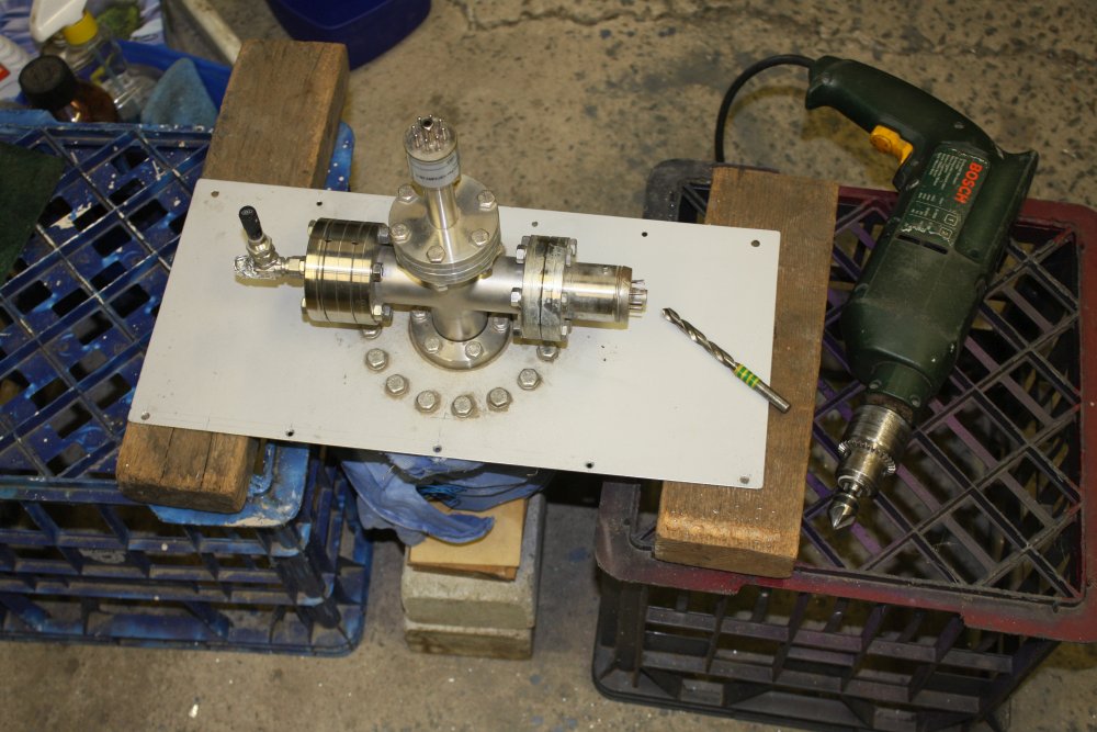 |
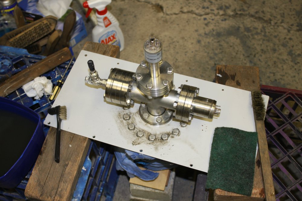 |
1. There it is, provisionally mounted. Not yet finished, since it needs a strengthener along the rear edge, and hold down screws to the rails.
2. Adding the strengthener. Cutout is for the RGA amplifier head box.
3, 4. Countersinking holes. A standard countersinking bit like in the drill there cuts very slowly. But standard drill bits are ground at a shallow angle that doesn't suit screw heads. So I have a few old drill bits that I've ground to 45 degree tip angle. They cut much faster, but one has to be very careful to not let them bite in and go right through. Also they have a tendency to make a triangular shaped countersink hole. Hence using them to go most of the way then the propper one to do the final shaping. A normal large drill bit is used finally by hand to remove any burrs.
5. FINALLY, starting to clean the RGA. Most of the outside can be treated like any old thing. Scrub, scour, wash, polish...
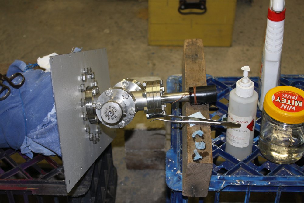 |
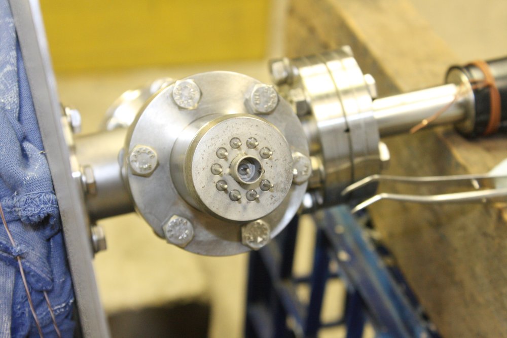 |
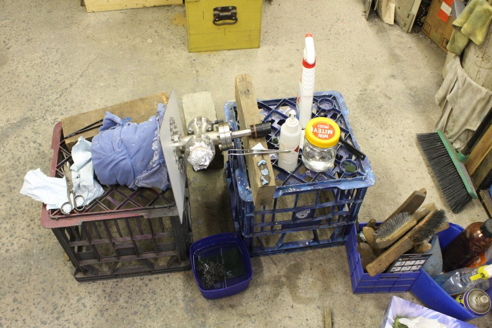 |
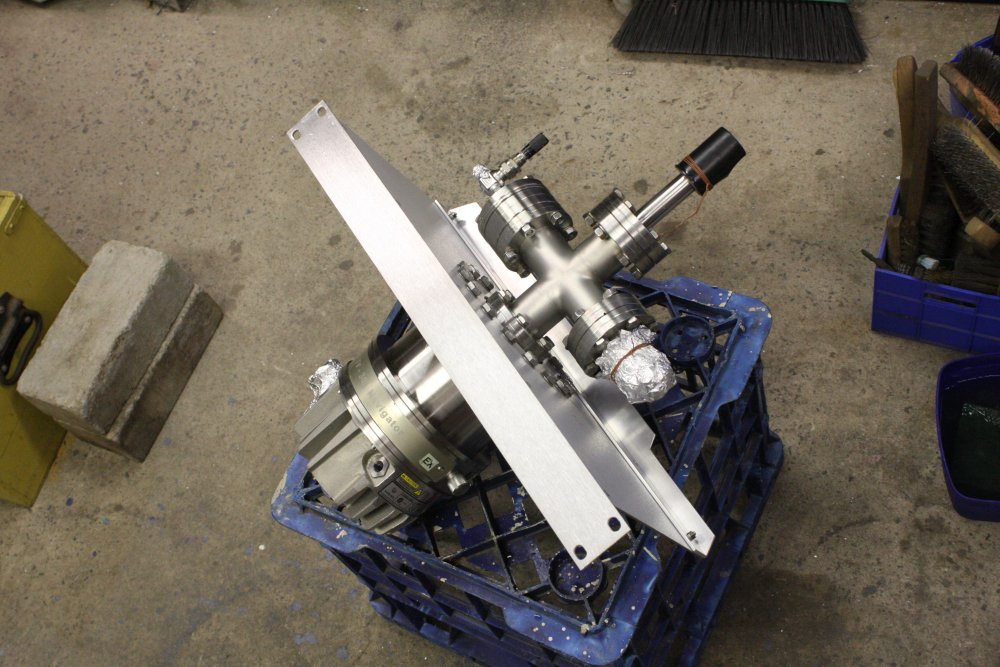 |
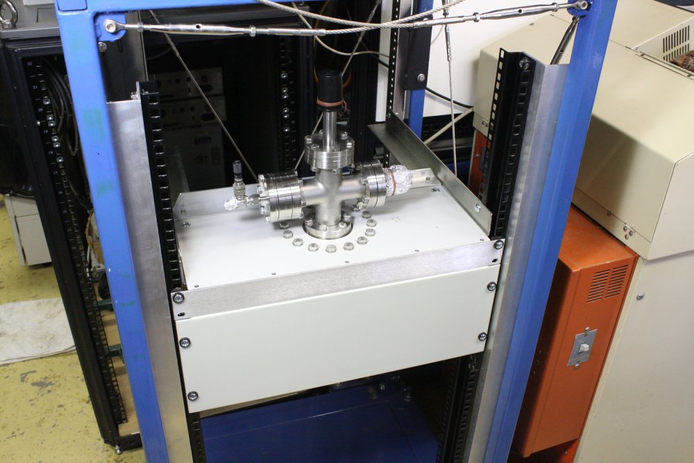 |
1, 2. But not this part. The connector to the RGA drive electronics, and in particular the critical center pin. That is the output, and connects to the extremely high impedance electrometer amplifier. Single electrons count... surface contamination is not allowed. Especially of the ceramic seal surface down the bottom there. All of those seals must not be scratched (mechanical risk of harm, plus forming a channel for conductive contamination.) This is why I didn't feel safe to even use fine grit sandpaper to remove that light surface rust around the outside. Nothing abrasive near those seals!
This connector got a phased cleaning - scrubbing with detergent and scotch pads (tiny, in tweezers), then multiple rinses with distilled water, then scrubbing with clean pads soaked in IPA, in tweezers.
3. Then immediately covered in foil. (I'd already done the same with the vacuum sensor plug, covered with a film canister in these pics.)
4. Nice and shiny! I'd also given all the bolts a tightening. In the process finding that one of them, on the inner base circle, was only finger tight. Amusing.
5. Annnnd mounted. I think it looks nice. Would be nicer if I knew it can be made to work.
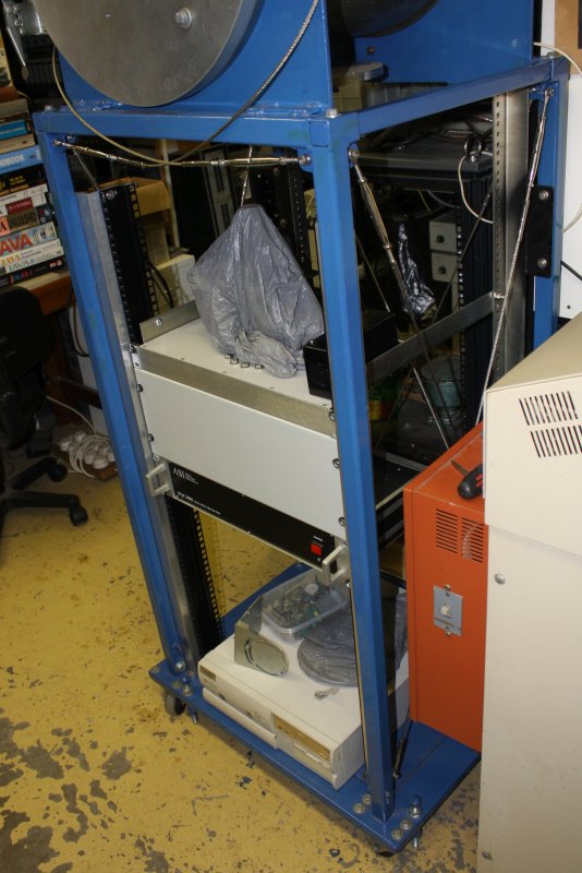 |
Wrapping up. Literally, as it may sit there for a while before I get back to it. Why let it get dusty again?
Later when I'm setting up one of the other turbo pumps and gate valve on the bottom port of the main vacuum chamber, this whole RGA set will probably have to be moved lower down in the rack. I knew that from the beginning, but it's easy to move them and I wanted them at convenient working height while doing this initial setup.
Also there is no point mounting that old PC on a slide-out tray yet, since I hope to be using a much better PC. Something more reliable, and with real card slots instead of the stupid sideways, awkward riser card thing in this one.
No point making a general ToDo list for this overall project, there's too much and too many unknowns still.
First Turbo Spin Up
20170302
After that I started back on some long overdue chores, unrelated to the vacuum project. Except... I did wonder about the vaccum gauge that came with the ASI DCQ2000 Mass Spectrometer/RGA. Did it work?
The sensor is a Bestech Model 912038 1203, with an 8-pin octal valve plug. The socket and cable are with the system.
Also on the label is http://www.bestechind.com USA ph: 1(973)882-2610
Web searching, Bestech are defunct. http://www.bestechind.com has been cyber-squatted since 2010.
One site lists:
BESTECH Headquarters: 1275 Bloomfield Ave. Unit 25A Bldg.5 07004, Fairfield NJ, United States.
Same phone number and URL. Googling so far finds no trace of a datasheet for the sensor.
Oh well. Next I tried for the display unit, which is a Varian Model 6822-08-520 SN 980903009
No luck for that model number either. Varian was taken over by Agilent, and there's nothing like that model number to be found. Of course someone with stronger google-foo than mine is welcome to prove me wrong. Please do.
[MUCH later I tried the obvious: searching for the model number written on the front — "Varian HV100". Which gets lots of hits. For eg "Varian HV100 High Vacuum Pirani Gauge Controller with Varian Transducer 6543-25-030". But still no manual. Sigh.]
So, not much to do other than try it. Since the original system was wired so the gauge was powered on all the time the main system power switch was on, it clearly wasn't going to be a sensor kind that would be damaged by operation at altmosphere. I wired a mains socket onto the gauge unit, reconnected the sensor cable plug I'd had to unsolder to get the display out of that RGA System Power Box, plugged it into the sensor, and turned it on.
The disply comes on, but blinks "0000" continuously. Hmmm... does that mean 'faulty sensor', or merely out of range?
I connected a rotary vacuum pump to the turbo outlet port, and pumped the RGA down. The rotary has an old mechanical vacuum gauge attached, which says the pump's ultimate result is "nearly 30 inches of mercury" plus or minus whatever the error is on a very, very old gauge. This fine old brass thing was rescued from an ancient coal-fired power station shortly before the building was explosively demolished. It looked like it had been in a coal boiler room for at least 50 years, which is where it had been. It polished up nicely. I should calibrate it against an actual mercury column someday.
Anyway, the Varian display was still blinking "0000". I like the green colour, but this blinking is not very encouraging. At this point I RTFM. Which, lacking any actual manual, consisted of reading the text on the front of the Varian display.
Oh, OK, ".01 to 100 × 10-3 mbar".
Hmm... a rotary pump should be able to get down into that range, according to my 1989 copy of 'Modern Vacuum Practice.' (Ha ha, ironic.) But maybe this old Javac DS60 can't? (Wouldn't be anything to do with the slapdash improvisation of bits of old hose I used to connect the assorted incompatible fittings, would it! Of course not!)
At this point it belatedly occured to me that right now I have the turbomolecular pump under good enough vacuum, and I could in fact turn it on. If the turbo controller was working...
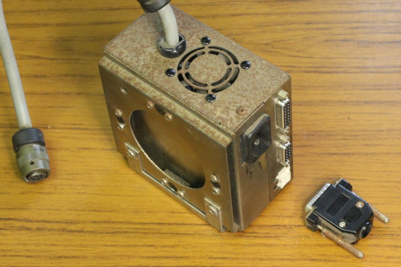 |
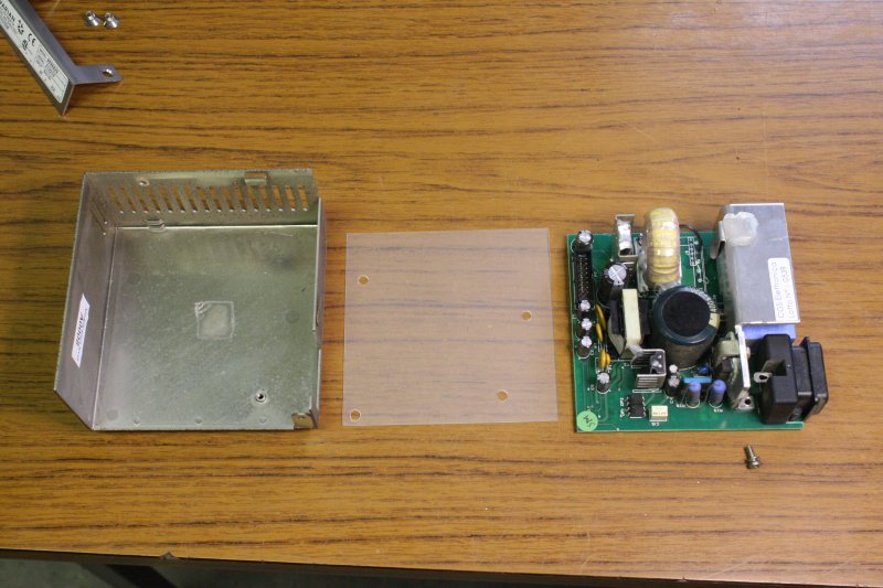 |
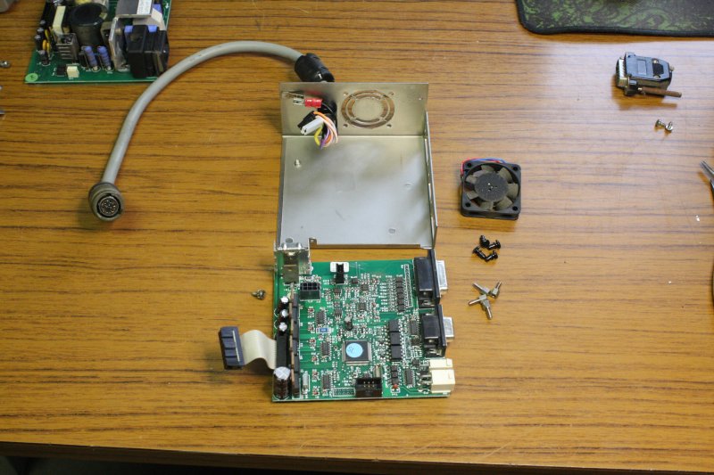 |
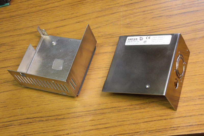 |
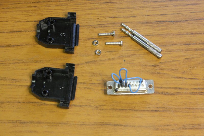 |
1. Well it might be working, but it's very rusty, from being in that damp weather-exposed environment for probably years. This is definitely something that needs disassembly and care, before being powered on.
2, 3. It comes apart easily. Nice design, power supply on one card, three phase drive card on the other. The electronics is pretty clean, I just brushed off the very small amount of dust.
4. The case on the other hand... What is this stuff? It's steel, but I don't recognise the surface passivation, which failed so miserably with a little humidity. Also that rust is a bugger to remove. It takes a LOT of pressure on the bench steel wire wheel machine to shift it. It's like some kind of super-rust, much stronger than ordinary rust and able to leap tall buildings with a single oxidation. Anyway, mostly removed. I left it in spots where the wire wheel would also remove labels and text.
I'm wondering what I should do to protect this surface. It sure likes rusting. Maybe wax it?
Pretty annoying really. Considering how much Varian probably charged for this, making it of stainless steel sheet would have been an insignificant cost increment. And amusingly one of the parts is a small bracket used only to carry a sticker with the system part number. And that's made of stainless steel and is spotless. Even el-cheapo power supplies from China have stainless steel cases these days. Varian were cheap bastards. But I bet Agilent won't have changed it.
5. The default startup plug, with screws cleaned. This plug makes the unit just start up when power is applied. See the manual I linked earlier.
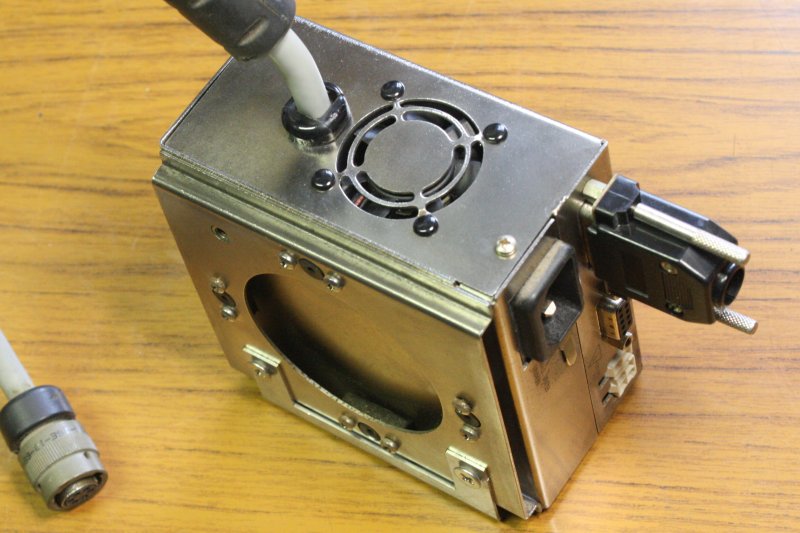 |
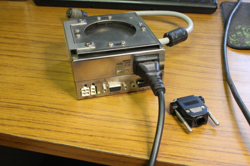 |
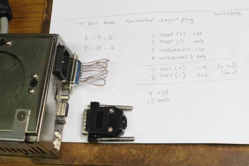 |
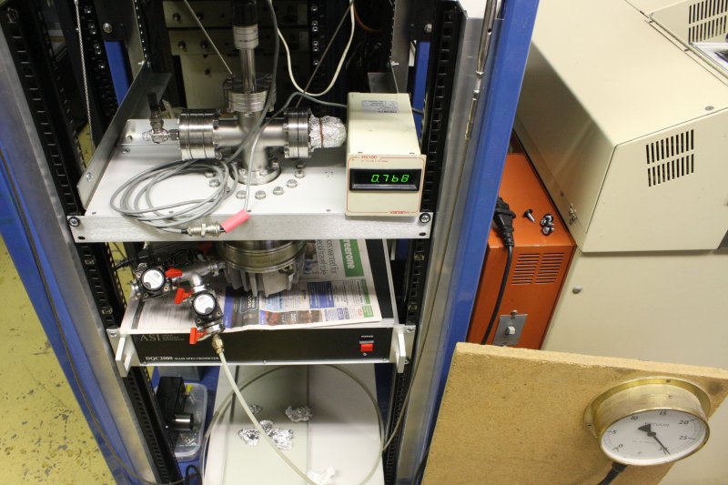 |
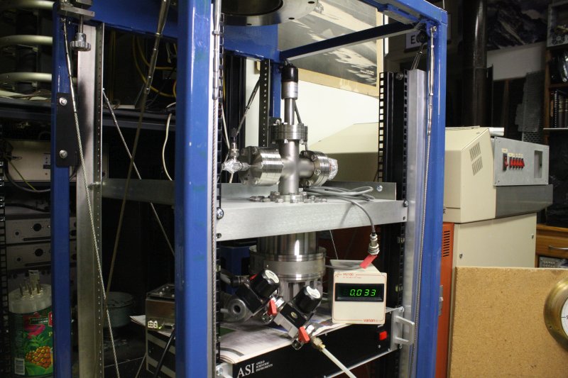 |
1. Reassembled, clean.
2. Powered up by itself. The LED does the right things — steady on when the controller isn't told to run the pump, flashing 'fault' when it is (because there is no pump.) This is extremely hopeful!
3. The manual recommends that after a long idle the pump should first be started in "soft start" mode. There are pins on the command plug to tell it to do that. This is one I wired that way. I think — it's ambiguous; are you supposed to also include the normal 'run' command connection? Anyway...
4. Connected the controller to the turbo, turned the rotary on again, waited a few seconds for the pump-down, then turned on the turbo. "Whiiiiine....." It's actually barely audible above the rotary, which is nice. Best of all, shortly after that the vaccum gauge display stopped blinking. This photo is a little while later, after I'd stopped partying (in spirit anyway.)
So wheeee! It's working.
5. Just another shot, after the vacuum gauge had gone down nearly as far as it was going to go. I don't yet know what this setup should reach, or how accurate the gauge is. Many things to be determined. Also the RGA assembly could probably do with a bake-out, after being left at atmosphere for years.
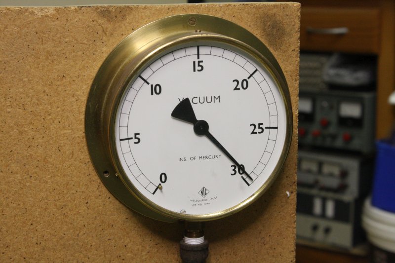 |
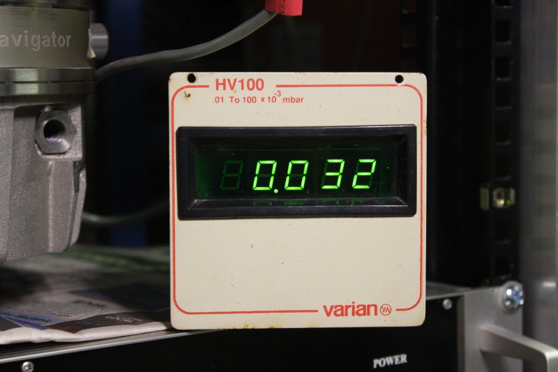 |
Final shots. The old brass gauge, and the Varian HV100, at the lowest it went on this attempt. Incidentally, in turning the turbo off and on a few times it became apparent that the HV100 starts blinking at around 20 × 10-3 mbar. Perhaps it's been adjusted that way, as an indication of when it's safe or unsafe to turn on the RGA filaments? I wonder if there was a printed RGA Operating Manual from ASI? (Which of course I don't have.)
Oh and yes I know. With the arrangement of valves I have on the roughing pump line in the photos, opening the left-most one while the turbo is running, would be BAD. So don't.
By golly, the turbo takes a loooong time to spin down after power is removed. I have a mechanic's stethoscope (like a doctor's one, only with a metal rod at the sensitive end) and so can listen to the turbo turning even when it's well below audible in the room. Doesn't sound like there's any problem with the bearings. Which are ceramic btw, with no oil at all. The turbo also runs very cool; after half an hour running it was barely warm. A small fan on the side will be all it needs.
Also, with only the rotary pump running I tested the little needle valve gas inlet control. It's working nicely too.
I probably won't be running this turbo again until I have a much better and safer pumping plumbing arrangement. One that can't backflow the rotary pump oil if power goes off, or suddenly vent to atmosphere if one of the crappy plastic hose adapters breaks. That lets me isolate the turbo from the rotary then vent the roughing line. No narrow bore plastic hoses, used because that was the only way I could connect a KF port to the hose on the rotary pump (groan.) And that has multiple ports for comparing vacuum gauges against each other...
Here ends this noblog entry. There's too much still to do, to continue in this already long page. Other days, other pages.