20200208 TerraHertz http://everist.org NobLog home Updated: 20200329
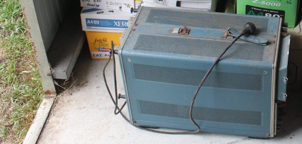
Normally I shun valve-based electronics, but this poor old thing was lonely in a garden shed all by itself, and its owner didn't love it and wanted it gone. It looked at me with puppy dog eyes and begged to come home with me. As if I'm soft hearted!
Which... sigh, I am.
With a bazillion projects running concurrently; it's not like taking on one more will have any significant impact on my rate of project (non)completion.
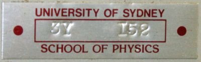
Besides, it has an irresistably cool name tag.
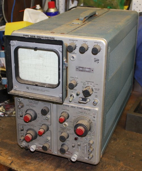
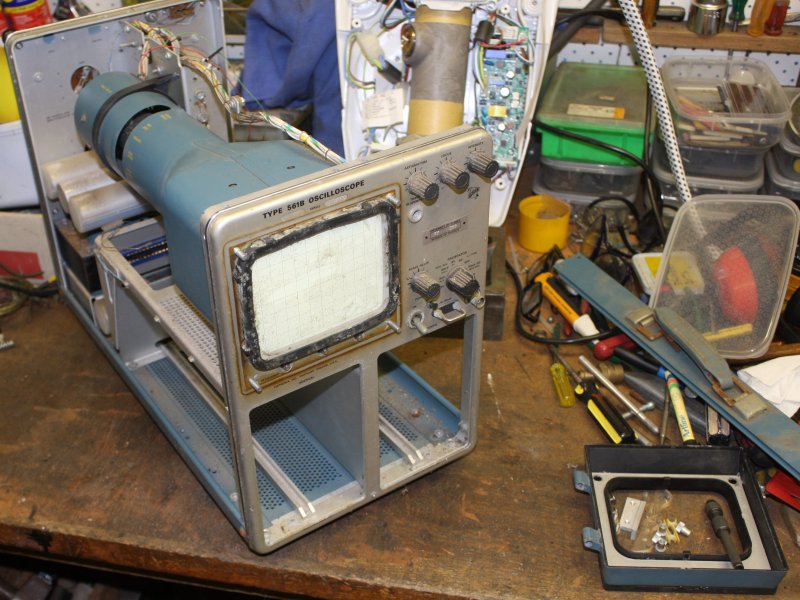
So here it is, making itself comfortable on my workbench. →
It's in pretty poor state. Age, grime, humid storage and the resulting surface corrosions, at least one valve obviously lost vacuum, and the carry handle is broken. So, before I touch the electronics, let's evaluate the physical condition. There's little point attempting a restoration if something broken is unrepairable, any needed parts are unobtainium, or there are just too many problems.
Otoh there's no use merely staring at it. To evaluate potential for restoration, generally one has to do some trial work. At least on the most obvious problems.
This article is dedicated to a Master of restoration of old Tek scopes, Martin, on eevblog.
I can only aspire to such spectacular results.
 |
 |
 |
 |
 |
 |
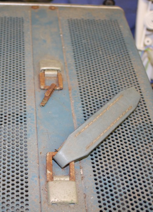
1. The carry handle has had it.
2. Mostly just dirty, but the camera shroud is diecast metal and has a bit of paint peel and corrosion.
3. More dirt that will clean off well, but one lever switch is missing the plastic end cap.
4. Plenty more dirt. But also some rust (transformer cover), light corrosion of anodized aluminium and surfaces of the large electrolytic capacitors.
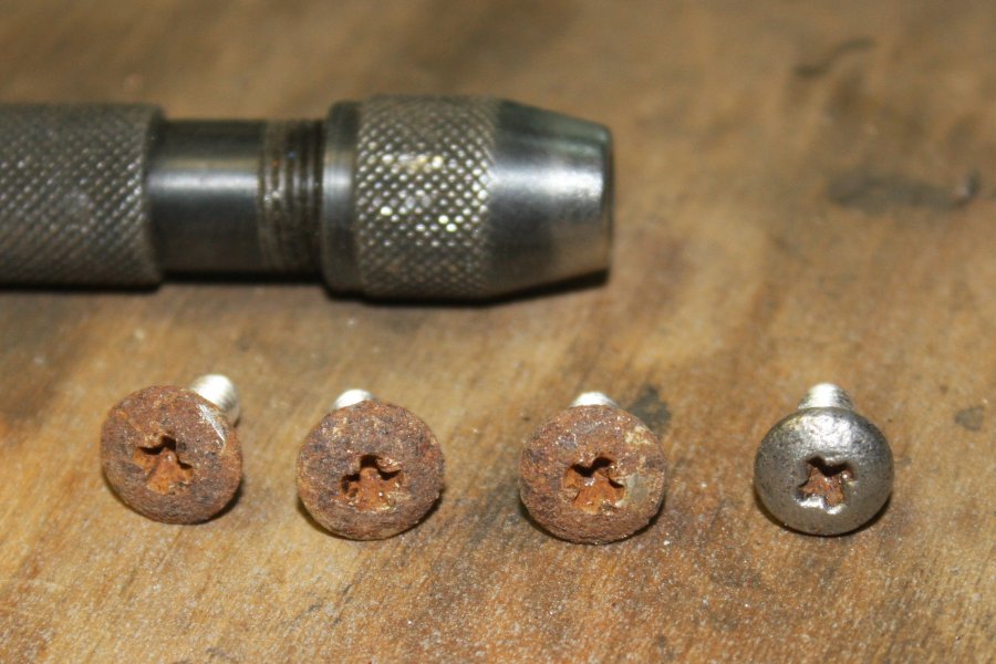
5. Rusty screws from the case top central strut. Best thing to do with these is replace with new.
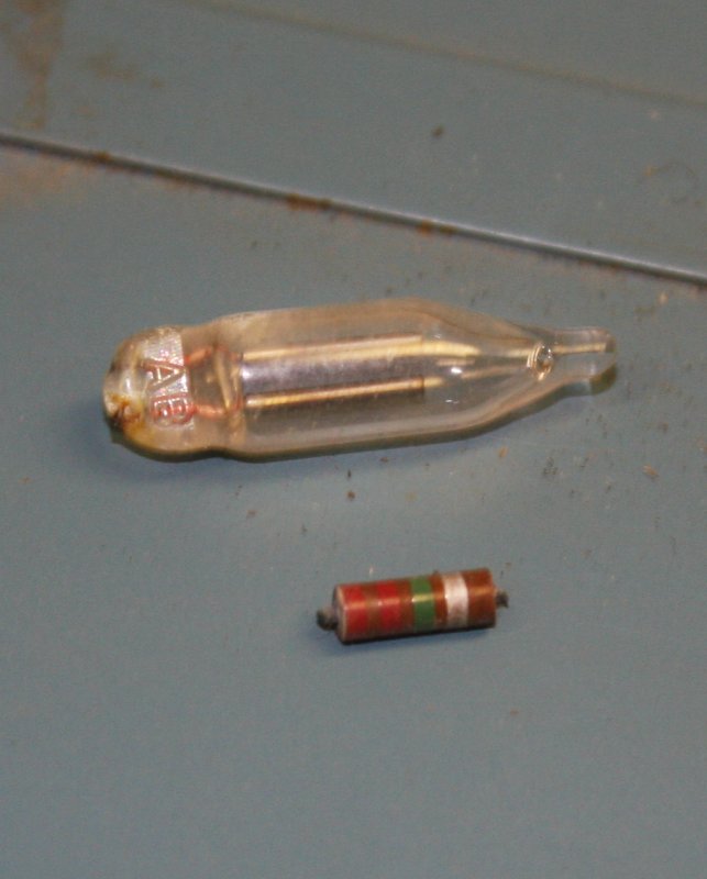
6. Hmmm... parts found loose in the botton of the case. The glass thing is a small neon bulb, which are commonly used in old Tek scopes like this. So that's a quest: where did it come from? It's a typical failure mode of these for the wire leads to break off at the glass, like this one. The remaining leads should be visible somewhere in the scope, but so far I can't see them.
The 2.2M resistor may not be from this scope. It's small enough to fit through a ventilation hole in the case, so may be a 'drop in.' The leads aren't broken off, they are cut.
 |
 |
 |
 |
 |
 |
 |
 |
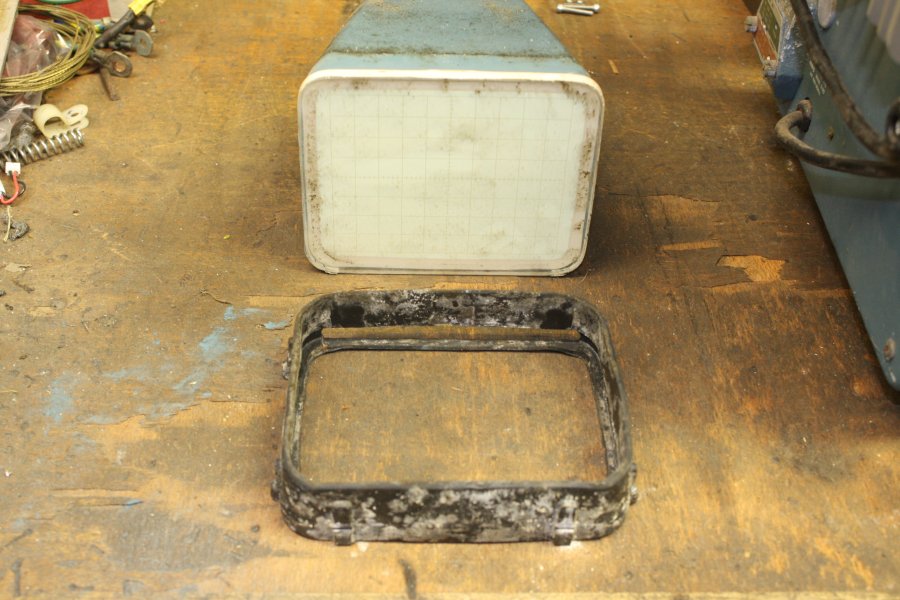
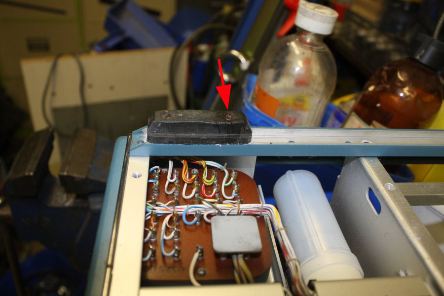
1. Urgh. The rubber protector for the front of the CRT is moldy, but still flexible. It will probably clean up OK, but must be removed to do so. How to remove it, is not immediately obvious. Maybe the CRT must come out first? Looks like it's 'read the manual' time for that one. Apart from that this is probably enough disassembly to allow general cleaning. Depending on what needs to be done about the rust on the transformer shroud.
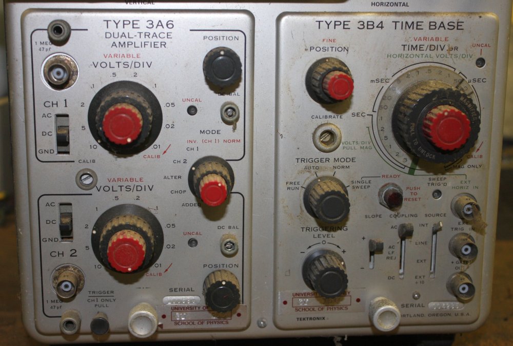
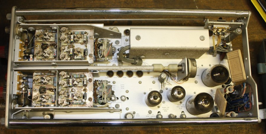
The Tektronix 561B was introduced in 1969. It has a bandwidth of DC to 15MHz and consumes around 178 Watts with plug-ins. Like most valve-based equipment it's a pretty good room heater.
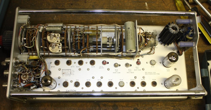
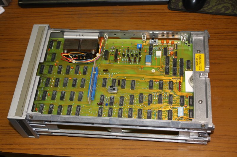
2, 3. The 3B4 timebase module.
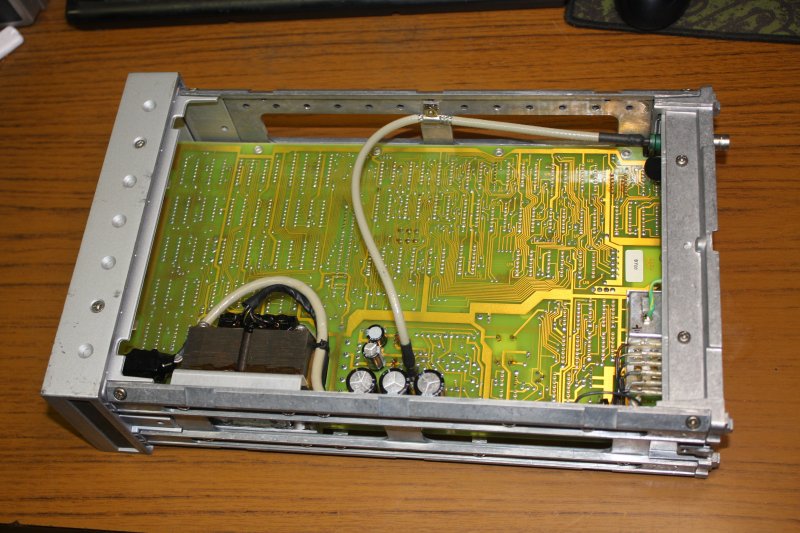
4, 5. The 3A6 dual input channel amplifier.
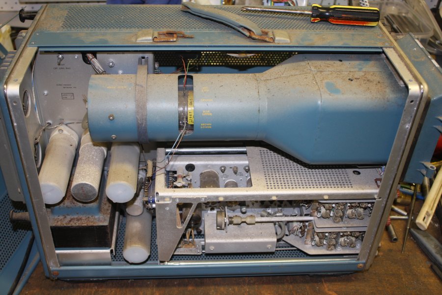
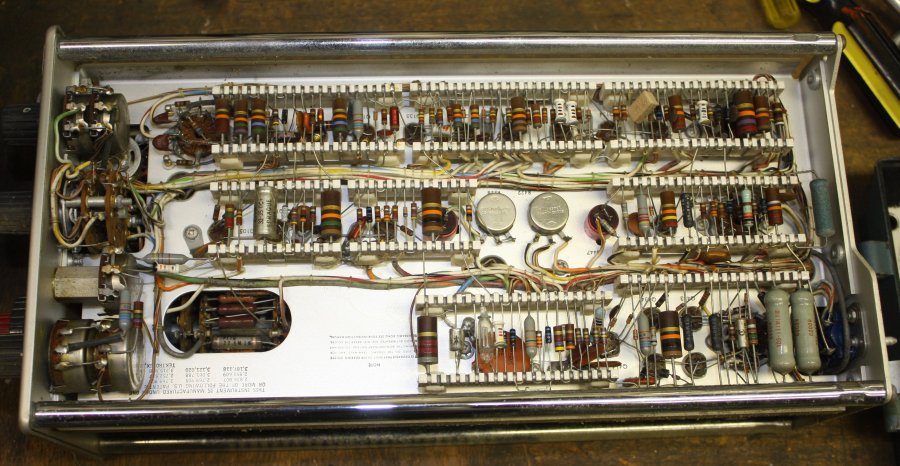
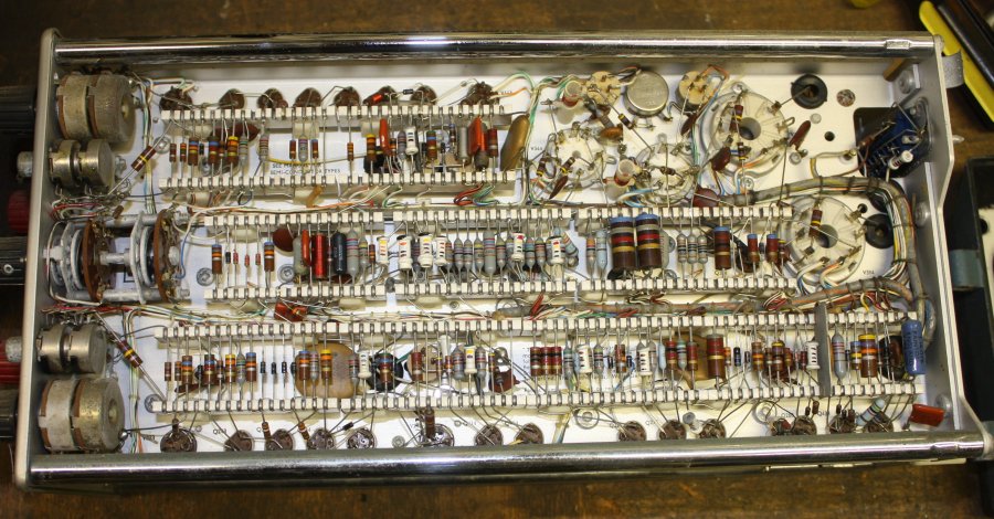
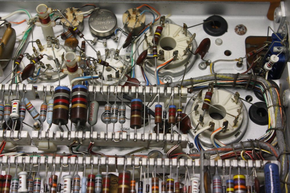
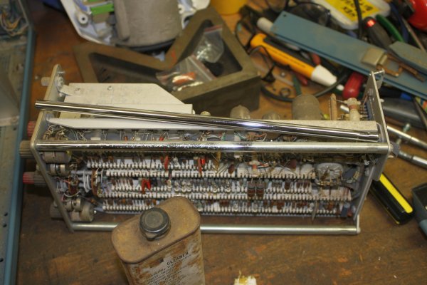
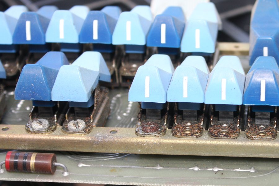
6. The Tek 560 scope series was introduced in 1961, before printed circuit boards became common. So modules for the series use pre-PCB point to point construction. Most components are mounted on ceramic tag strips, with slots holding soldered junction points. One trap with these, is the solder has to be a special type with high Silver content. If more common solder containing Lead is used to repair these, the metalization separates from the ceramic. Which is an unrecoverable disaster. Supposedly some of these old Tek scopes with ceramic tag strips contained small rolls of the special silver solder, but I don't see any in this scope. If I need to do any circuit repairs in these modules, I'll have to find some of that solder. Not sure how difficult that might be.
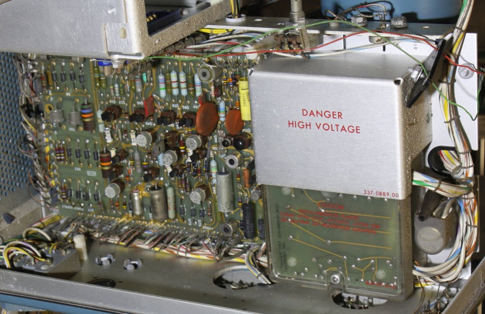
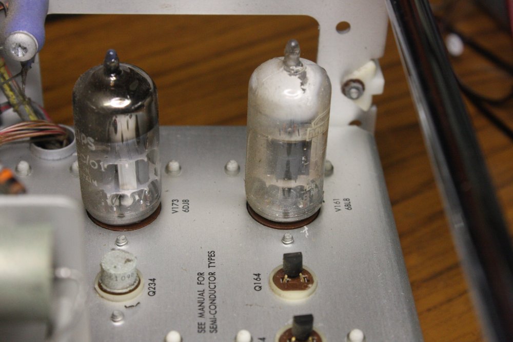
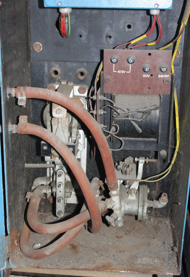
7. By the time Tektronix added the 561B to their 560 series, printed circuit boards were a thing. Hence this scope frame has most of it's power supply and EHT circuitry on PCBs. Also this section is entirely solid state, no valves. Yay.
8. Of these two valves, the one on the right is dead. During manufacture, after the tube is evacuated and sealed a chemically reactive film of Barium is evaporated onto the inside of the glass. Induction heating is used to heat and evaporate the barium from a small ring-shaped reservoir. The coating on the inside of the glass has a dark silvery mirror appearance, as seen in the valve at left. It's called a 'getter', because its purpose is to react with and hold any gas atoms that somehow end up inside the valve. Thus maintaining a good quality vacuum, required for the electron tube to work.
When air does get in it's visually obvious. The silvery layer turns white due to the Barium oxidizing, and tends to peel off. As in the dead valve here. Fortunately this dead "6BL8" valve is cheap and easy to obtain — "The Valve Store". That's if I don't have any in my collection, which I might. (No, they are not catalogued. Just some boxes of random salvaged valves.)
 On both plugins the chromed slide rods are very tarnished and rough. How difficult are those to clean?
Fortunately they can be removed one at a time, without disturbing anything else. Remove the rear screw, tilt the rod outwards a little and unscrew it from the fixed-in-place threaded stud on the front panel.
Wipe on some chrome cleaner, let it soak into the tarnish-gunk, then a light rubbing with stainless steel wool scrapes it off. Wipe on some more chrome cleaner (it includes a wax that fills microscopic pores in the chrome plating) then wipe with a clean cloth.
The result is an almost new looking chromed rod.
Next repeat on the remaining seven.
I wish the carry handle would be so easy.
 |
 |
 |
 |
 |
 |
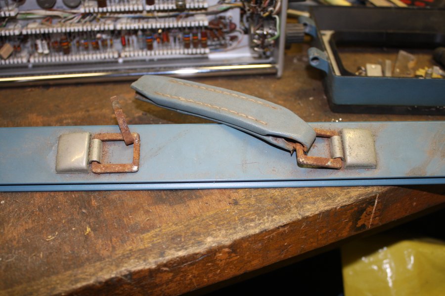
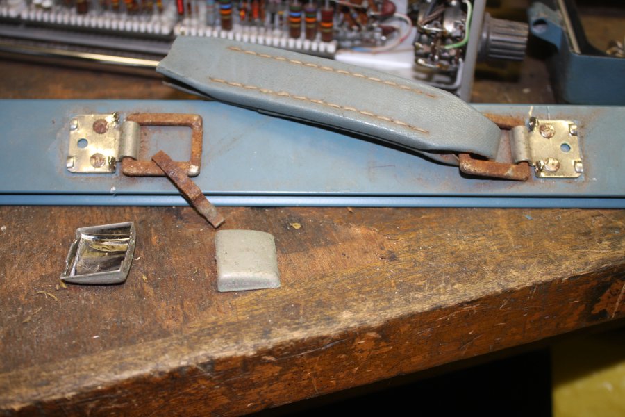
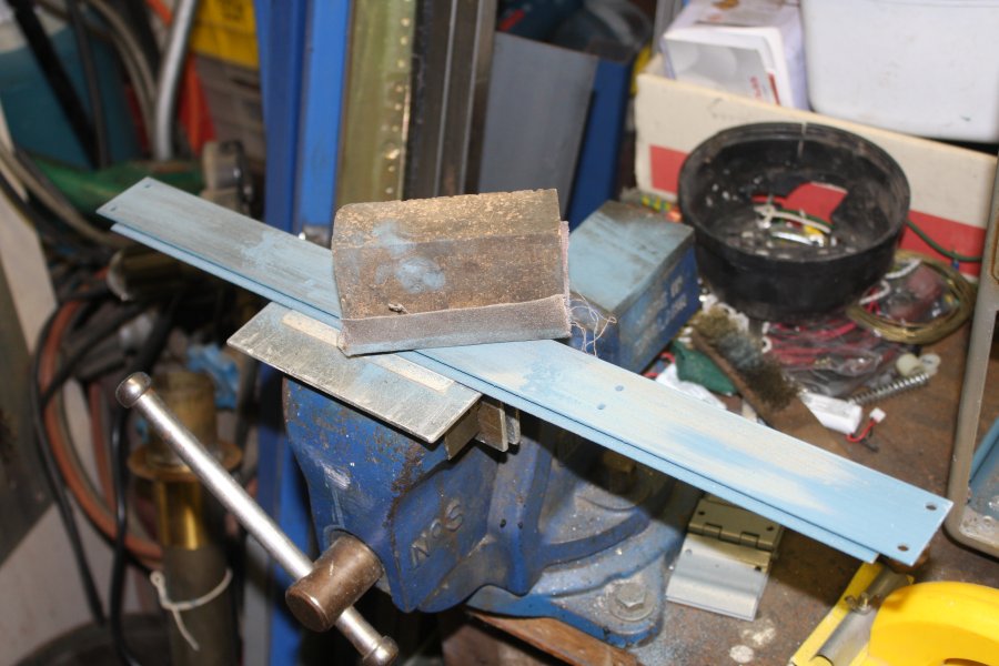
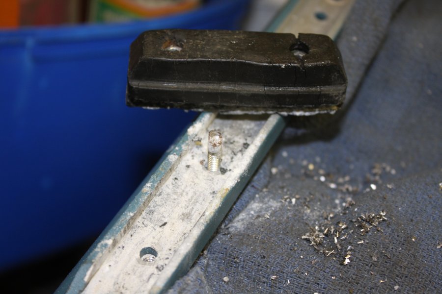
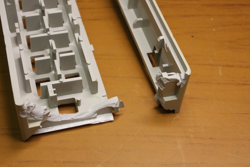
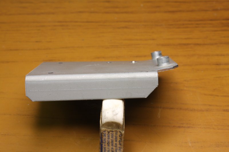
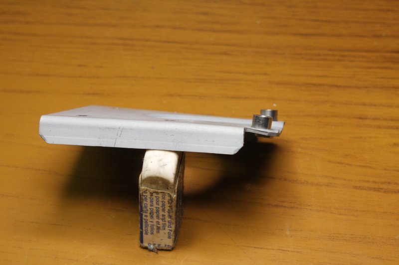
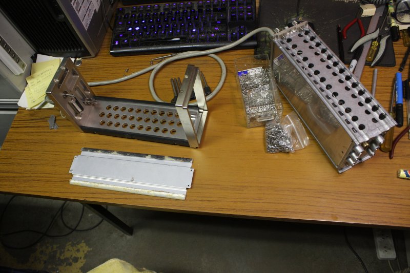
1. Count the broken and corroded things.
2. Annnnd, it's rivetted on. What's on the other side?
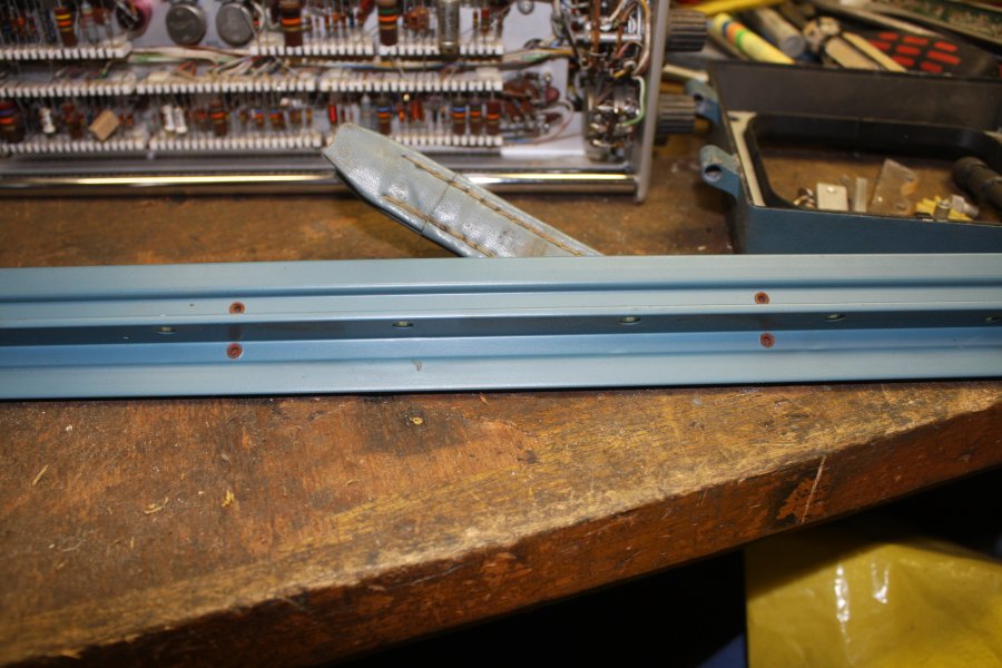
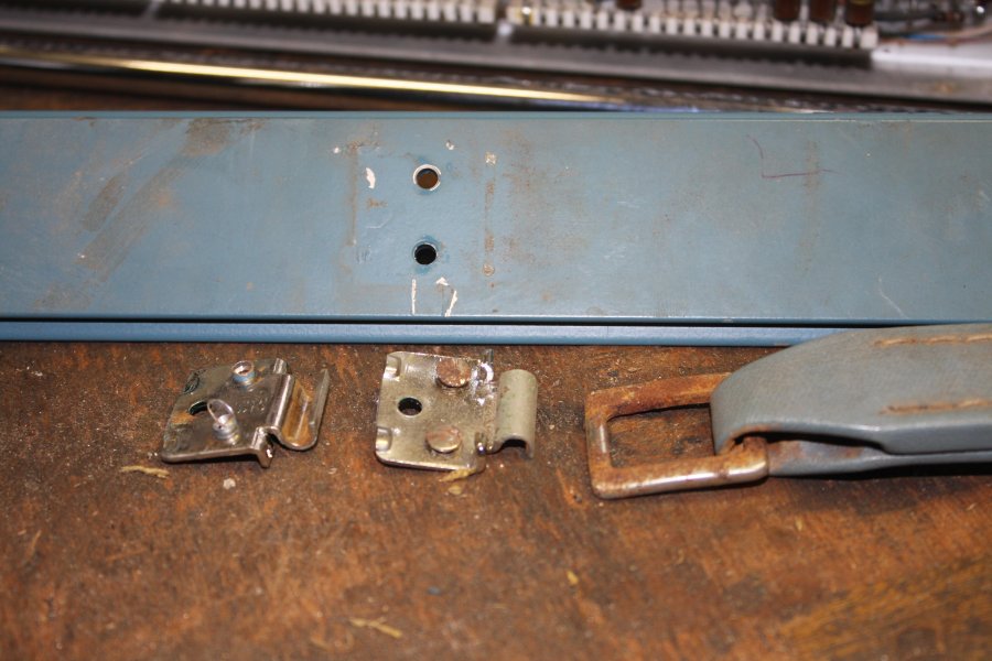
3. It turns out those caps on the brackets are clipped on. Not hard to pry them off.
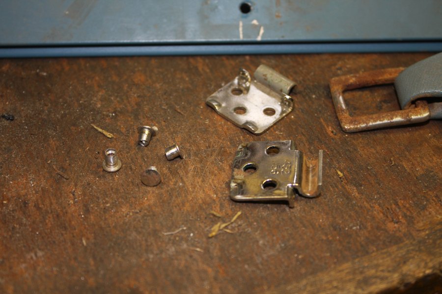
4. After drilling the rivets, with an undersize drill so as not to damage the aluminium rail, then punching them out from the rail. But the rivet shafts are slightly squashed and expanded too, and still won't come out of the steel brackets. I don't want to stress the brackets by punching the oversize rivets out. Can't grip the rivets to drill them out of these. Hmm...
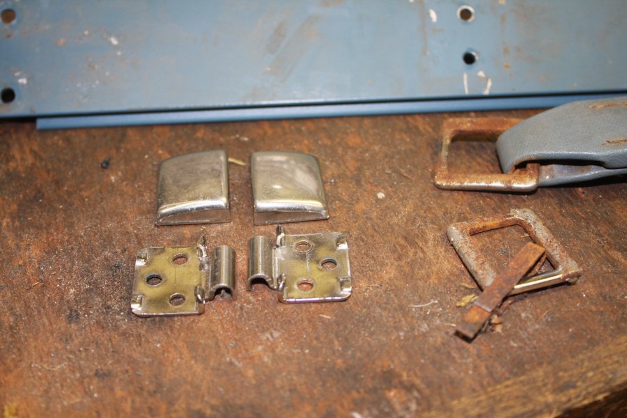
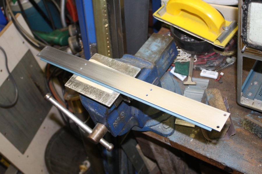
5. Removed. The solution was to very carefully touch the rivet bulged shaft side to a belt sander, letting the belt spin the rivet in its hole, and gently thinning the rivet shaft down. Till they fell out.
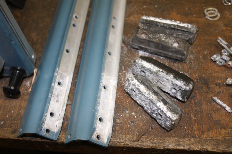
6. The brackets cleaned up. Could do with a bit more shine, but later, after I work out what to do about the handle and those rusted shackles. Sandblast and re-chrome? I don't see how the handle can be repaired, so perhaps whatever I replace it with will come with new shackles.
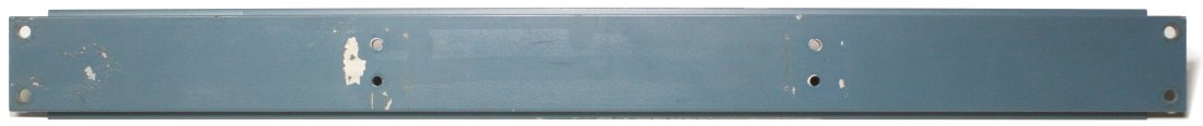
First though, the metal rail. It has 'worms under the paint' corrosion (common with old aluminium) and the paint is flaking in spots too. So clean and repaint it. Which raises a problem — obtaining paint matched in colour and gloss to the original Tektronix blue. Web searching on this topic brings up a suggestion of a brand & colour canned spray paint that is 'pretty close'. But that's in the USA, won't be available here in Australia, and anyway what is 'pretty close'? I want it indistinguishable from the adjacent blue case sides. Nobody seems to have posted the actual colour code in any form, such as a matching Pantone number. Typical.
An automotive paints shop mixed me half a litre of paint supposedly matching colour and gloss to the Tek blue. We'll see.
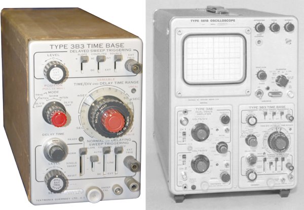
Meanwhile... I remembered I had an old Tek scope module in my 'museum', that might suit this scope.
It was a piece I'd kept, never intending to actually use. Just to show people this style of electronics construction. Which is quite pretty, and not something anyone would normally see these days. After a little digging I found it.
Ha. It's a 3B3 Time Base, and not just compatible but the model shown in the 561B manual's illustration of the scope. Since it's still in an original cardboard protective carrier, it might actually be 'new' (as in old but never used.)
Oh, and it has several 6BL8 valves, so now I have swap spares.
Then while looking that up online, I found an original 561B scope manual on ebay for $10. The PDF manual I'd downloaded from Tek Wiki is relatively good quality compared to typical PDF scans of old manuals (usually abysmal), but it still has PDF-nature, and sucks.
Hmm, because this gear is very old and obsolete, the beautiful original Tektronix manuals are so cheap!
A little more ebay hunting, and I ended up with a set:
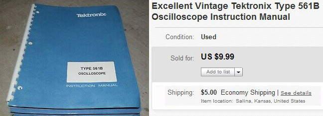
  561B  Scope          $10
  3A6   Amp            $5
  3A9   Amp            $12
  3B3   Time Base      $10
  3B4   Time Base      $4
  Scope camera systems $15
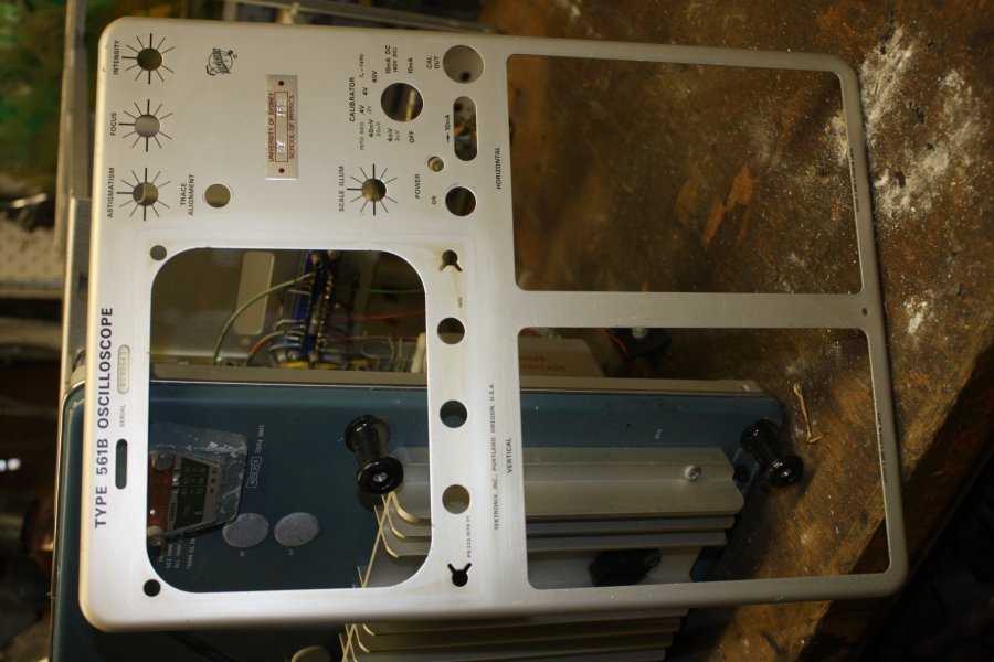
Manual on ebay. (Photoshopped for fit!) →
 Camera systems? What camera systems?
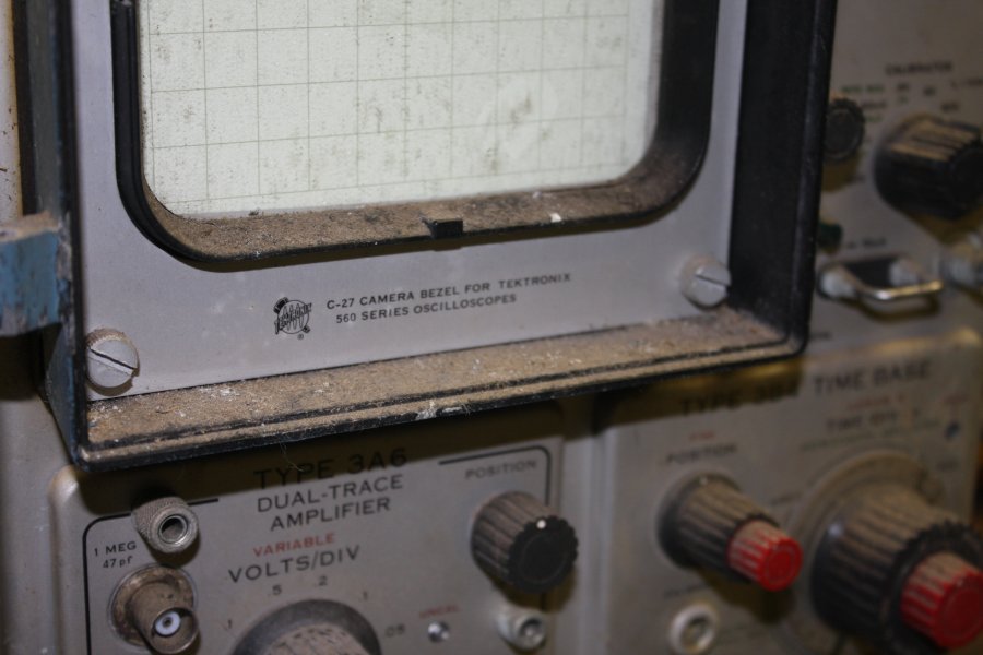
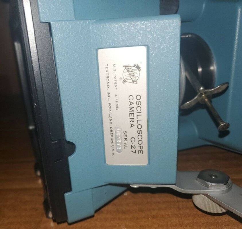
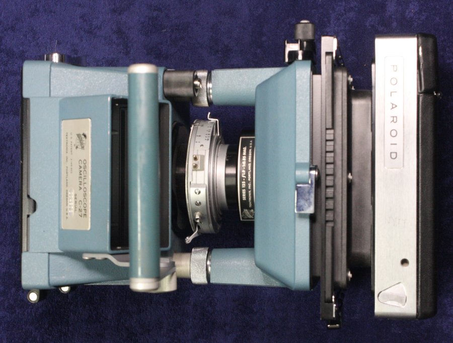
This scope is fitted with a camera mounting shroud on the CRT face. On that it says:
Googling that, I found a few C-27 scope cameras listed on ebay, most at absurd prices. For something that requires Polaroid film packs, which last I heard have been unobtainable for decades. Making the camera as-is fundamentally useless. Not to mention only fitting an oscilloscope made in the 1960s, ie 50+ years old.
And requiring that special mounting shroud, which most scopes and the cameras on offer are missing.
And then, I found an ebay auction of a very nice condition C-27, with a starting price of $0.99. Still has a couple of days to run, and no bids so far. I expect that unless there is some other idiot like me restoring a 561B scope for historical reasons, and theirs happens to have the camera mount shroud too, no one is going to seriously bid on this item. Maybe someone wanting to pull the lens or shutter out for something else? So I set up a snipe bid with a limit of $27 and waited.
Meanwhile I checked with the seller of that 'camera systems' manual if it covers the C-27. It does. So I bought it. Partially just for historical interest even if I don't buy the camera.
 |
 |
 |
 |
Lucky! I won the camera too, for 99 cents.
As expected, no other bidders.
I assume the seller was disappointed, so when paying I added a note thanking them and mentioned the camera will be mated with a 561B currently under restoration, and the set may be on display at times with the Australian Computer Museum Society.† Which is possible, if they ever get a public venue. In the meantime it will be appreciated by others in the Society.
Now it's in the post and will be for a while. As always, fingers crossed it survives the shipping ogres.
Remember those rusty screws for the top strut? I'd been trying to find new ones. In stainless steel, so they never rust again. But not having much luck. Initially I didn't know what that head shape was called. I'd guessed 'dome head', but turns out that is higher profile and smaller diameter. My favourite fastener supplier is nearby, Premier Fasteners, but since they became 'under new management' a couple of years ago they went to the dogs. For one thing, no more walking in with some weird sample screw and having a staff member help rummage through their warehouse looking for a match. Now they only accept phone orders, then coming in later to pick up the order once it's ready. A stupid move on their part, because that makes 'don't quite know' enquiries/orders impossible, and that will totally piss off every engineer who needs a few of something odd. (Though I always bought a box full of whatever, to make it worth their while.) Anyway I'd had a bad feeling about where this would end up, once they started getting all formal like that.
Because of Premier Fastener's new stupid attitude, I didn't go there first with my rusty sample screw. I'd quickly worked out it was a UNC #8 thread, aka 8-32. An Imperial thread of course, since of USA manufacture in the '60s. It's 3/8" long, again an imperial/inch size. But what tf is that head shape called?
I dug through my box of salvaged US stainless steel screws. And found just two exactly right. Not four, as needed. Grrr...
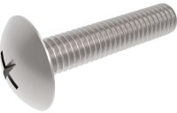 Then looked online. Ah ha. A supplier in the UK has the exact thing: "8-32 UNC x 3/8 inch Phillips Mushroom Screws (ANSI B18.6.3) - A2 Stainless Steel" (Pic is CAD, and not the right length.) →
I learn this head style is called "mushroom." Apt I guess.
But they want US$8.35 plus postage for 25. And the long delay. Not unless I'm desperate.
Next I tried dropping in at Industrial Fasteners, Mortdale on Tuesday, on my way over to mum's place to clean her gutters in case it rains buckets again like recently. No luck there, they suggest I try online. Sigh.
Today (Wed 20200212) I meant to phone Premier Fasteners and ask if they had them, now I know the name. But... my landline is out of order again. Telsra "planned maintenance" for over a week, my arse. This happens repeatedly lately and I'm sure they are just trying to make subscribers give up on landlines and move to NBN. But no, f*ck you Telstra, I want to keep a good old reliable (used to be anyway) wired landline. Screw the NBN. So today I'd have to call and sit waiting while on a time-charged prepaid mobile. I'd rather not.
In the afternoon I needed to go over that way anyway, so drove over to try my luck. I forgot they always close at 3pm, and I got there about 3:15. But it wouldn't have made any difference to get there earlier, because... sad surprise. There is a 'For Lease' sign out the front.
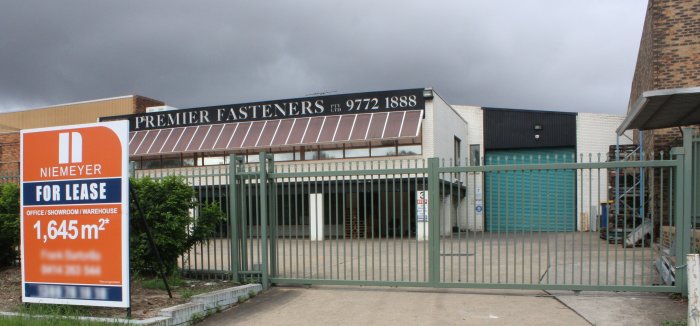 Something of a timing coincidence. I spoke to a guy in the next door factory, and he says the 'For Lease' sign went up just yesterday. Back home, checking their phone number and web site, I find both are terminated. So they are closed, not just moving. I wonder how long they have been closed?
How could the best 'nuts and bolts' bulk supplier in Sydney have gone broke?
Dammit. For my general workshop needs, this is a disaster. I seriously relied on them. Don't know of any equivalent supplier, let alone less than 10 minutes drive away.
I can't help suspecting it was deliberate; new management put in by the investment fund that bought the place, intentionally destroying the company as part of the Globalist de-industrialization agenda. Every single change they made, seemed to me to be clearly to the detriment of the operation.
Yeah, yeah, you'll tell me 'just stupidity.' Maybe, but I don't think so.
I want to see if I can contact some of the staff, ask them what happened.
Also, what about the stock? Is there going to be an auction? Some investigations needed.
On Thursday I went back and managed to speak with the manager and a guy from the auctioneers, apparently the only ones there. It's in liquidation, and had closed on Jan 23rd. As expected, to any questions about the business's profitability or why it closed, his response was "I can't comment." The only thing he did say was that the instruction to close it 'came from above', presumably meaning the investment company that was the owner. The original owner was an actual person, who I'd met and thought was a geat guy. Others have made the same observation to me about him, who built the company up from nothing, and was always thinking kindly of his customers.
One thing I did notice in this brief conversation. The manager (ex manager, since there's now no business) had a most smug and self-satisfied air the whole time. I read him as having a feeling of 'mission accomplished.' I don't think I was imagining it.
Anyway, it's gone. Sad, and reminds me of another sad fail, but let's move on. What to do about getting those screws?
 There's always Aliexpress. Anything you want, so long as you don't want it fast. On Thurs 13th I ordered, despite knowing it's Chinese New Year holiday period and possibly TEOTWAWKI, starting in China. Partly as a backup, partly just to see what happens. Others are wondering if packages from China might be contagious; personally I'm more curious to see if/when packages resume shipping from China. Many ramifications if they don't restart soon.
Annnnd... after placing that order I noticed it and all my other orders in the last month state "will be shipped within 16 days 5 hours 38 minutes." Oh? So now there's a specific restart time, the same for all sellers? That's new.
I started an electronics forum thread about this 561B restoration, to ask for some advice. Any comments?
Otherwise most of Friday was taken up with settling in a couple of cats to be minded here a few days. They both grew up here, but have been moved away for months and now don't remember anything of this place or the other cats. Not even their own mother and siblings. Cats have very small brains, the poor things. Also a friend visited.
Saturday, back on the screws hunt. I've been meaning to go visit The Stainless Shop, in Taren Point for ages. Never got around to it, partly because the drive is about 45 minutes in traffic. I'd checked, they do have those screws in stock. About to order them online I thought no, just go there, pick up the screws and have a browse too.
 Just a browse? Sure, I won't buy anything else. Ha ha ha...
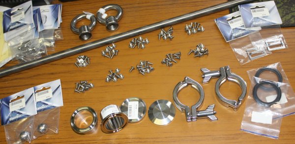
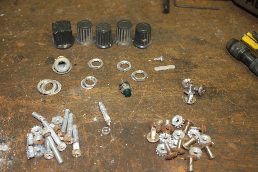
The screws were Au $9.86 for a hundred. A lot cheaper than the Aliexpress price, which was a surprise. The rest, well that's a bit over $200 worth in the picture. Briefly:
The two big Eye Nuts and M16 threaded rod are for the house. To construct climbing gear anchor points on the 2 storey house's roof ridge line, for gutter cleaning without falling to my death. My 2-storey workshop that I built myself, already has such rings along the roof ridge.
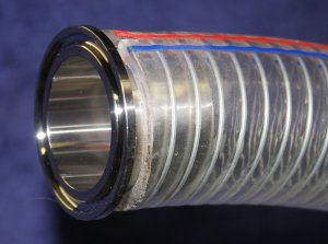
The 38mm triclover fittings are for a fat roughing pump hose on my vacuum system. They are a perfect fit to the hose.
Neither the tubing or these fittings are suitable for high vacuum use. Both the PVC tubing and the triclover rubber (EDPM?) seals will outgas. But these will only be used for rapid initial pump-down of the chamber using a very big rotary pump, then this will all be isolated from the vacuum system as better (slower, but higher ultimate vacuum) pumps take over.
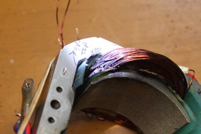
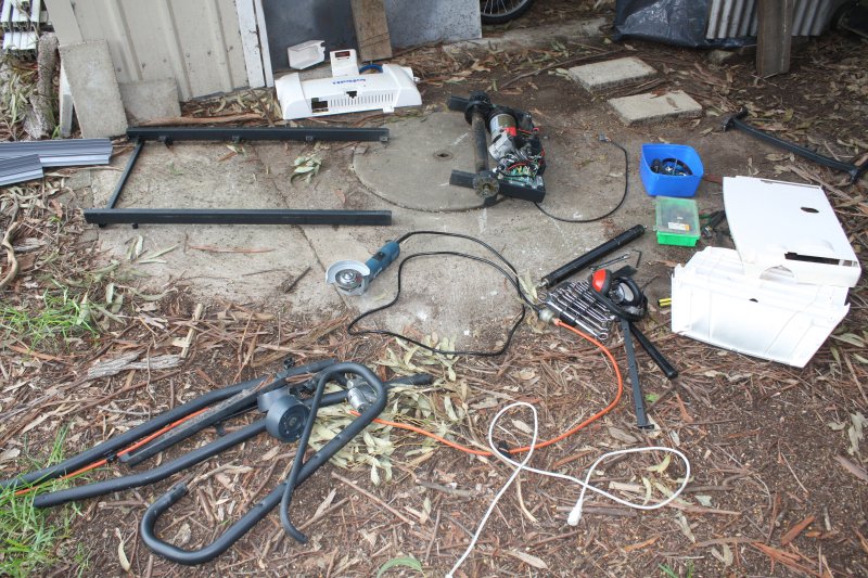
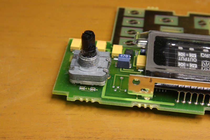
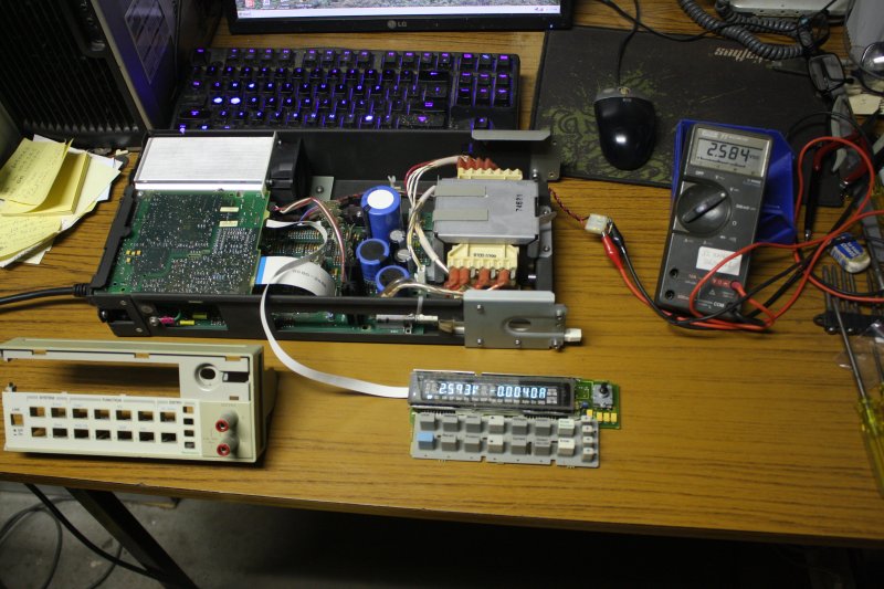
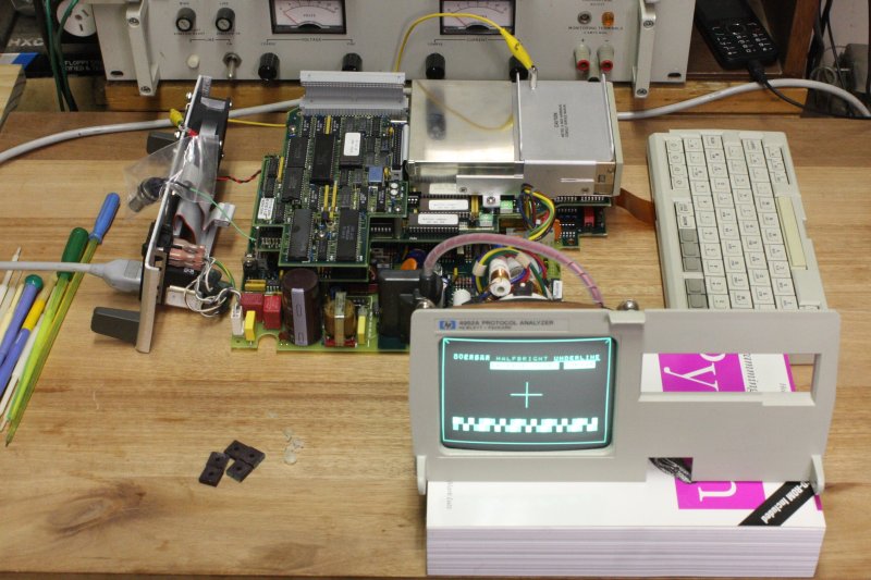
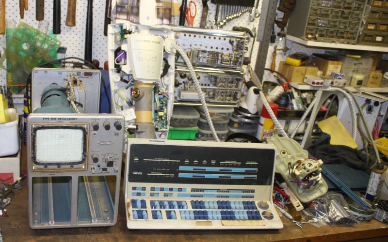 Typical state of my workbench. Currently the 561B scope frame, a PDP-15 console (here for a quick clean before being packed away again), an electric lawnmower motor to be fixed if possible (broken wire in field coils), the power distribution module for my HP-1000 system rack (replacing dead fan) and in the rear a fancy steam iron boiler unit. It's consumer junk and died due to a bad design flaw. A silicone hose that in operation contains steam, had split. Result: steam loose inside the plastic shell. It condensed on the electronics board, which has mixed mains AC and low voltage logic sections. The steam condensate was of course distilled-pure so there's no visible corrosion. But apparently still conductive enough to fry something. It's not working right, there's no service info available and it turns the boiler heater full on all the time, so I'm scared to run it for long. Need to enquire about manufacturer service cost.
 |
 |
After painting this, it will be about time to try the scope electricals.
Signs of life, does the CRT work, etc.
Before beginning construction of a new handle. Since that will be a project in itself, not worth doing if the scope is perma-dead.
 |
 |
 |
 |
 |
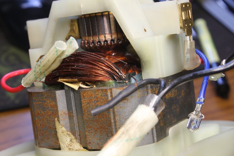
1. The arc-melted wires are right in the center of this pic.
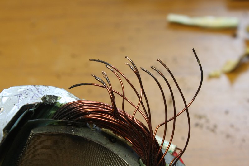
2. Starting to dig. Hmm, it's more than a few turns damaged. I'm saving the wire as I pull bits off, in order to be able to count the turns later. The number of turns I have to replace.
3. The damaged area is down inside the slot, difficult to see.
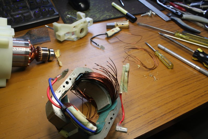
4. About half the coil unwound, and the melted zone is still present. Repair prospects becoming slimmer.
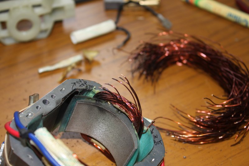
5. OK, down to about one third of the coil left, and there are still melted wires. What a ruin. I can't see myself rewinding the entire coil. Apart from being very tedious it probably takes some skill to get the wires packed tightly, and I wouldn't be able to do it well enough to fit the required number of turns. Which is a lot. The removed wire is in the background, one turn per length. Easiest way to keep track. So I give up for now. The bits all go in a box, that's transfered to the 'maybe one day' area. No more time spent on that today. Later I'll enquire about the cost of a new motor. If too much, just recycle the whole thing.
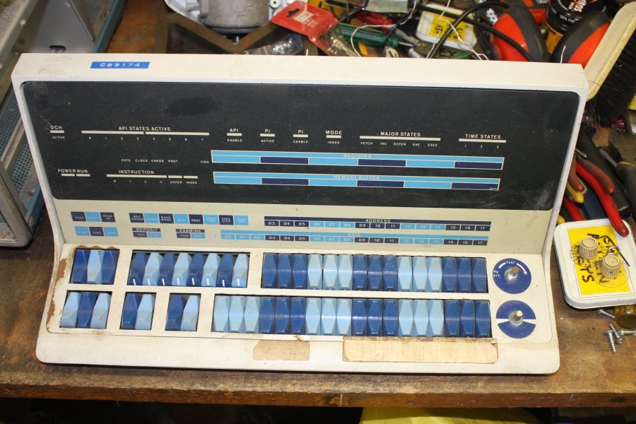
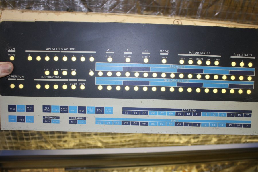
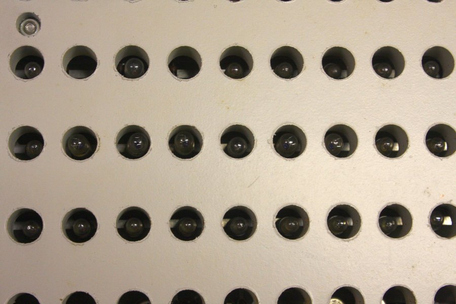
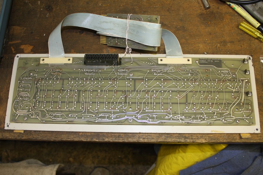
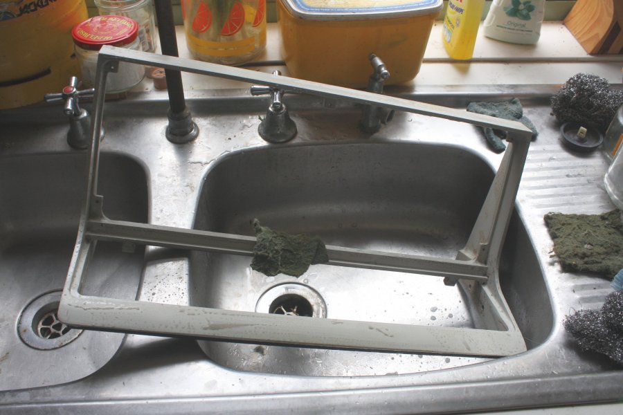
The PDP 15 console is an entirely different matter. It's of high historical value, worth preserving. There's no question of getting it going, since someone in the past discarded the Digital Equipment Corp mainframe it's off, keeping just this panel. There may be things about it that can't be 'fixed' for several reasons: age, absent documentation (I don't currently have any PDP 15 doco) and some things that 'fixing' would diminish the historical accuracy. For instance the console uses small filament light bulbs for all the indicators. Many of which will likely be dead. But the piece can at least be stabilized.
Of DEC's line of 18-bit machines, the PDP-15 was both the last version, and the only version constructed from TTL integrated circuits rather than discrete transistors. Marking the end of one era, and the beginning of another.
 |
 |
 |
 |
 |
1. Starting disassembly. It feels like both the rockers fascia and the lights panel are 'floaty'; not really attached apart from the pot nuts on the two knobs.
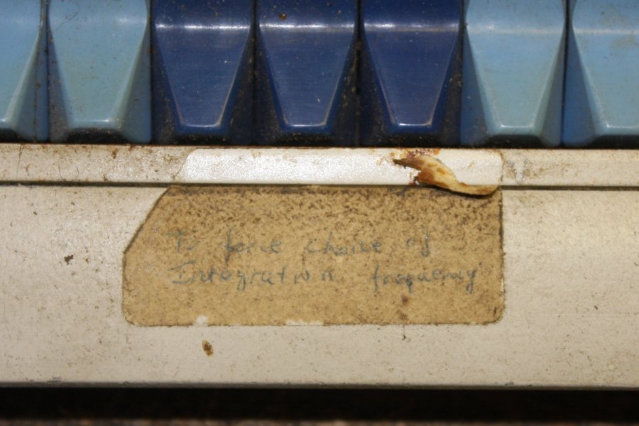
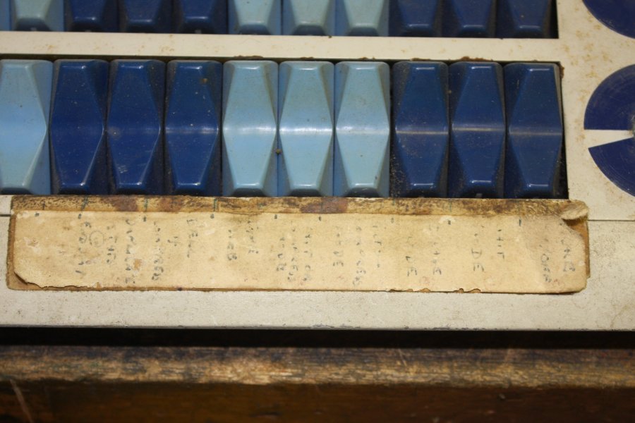
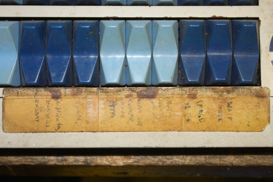
2, 3. I'll remove these old handwritten notations, but hopefully can work out from the photos what they say. Quite faded and indistinct.
4. Turns out the long one had another sticker underneath. Sort of an antique computer version of a Palimpsest. Also indistinct.
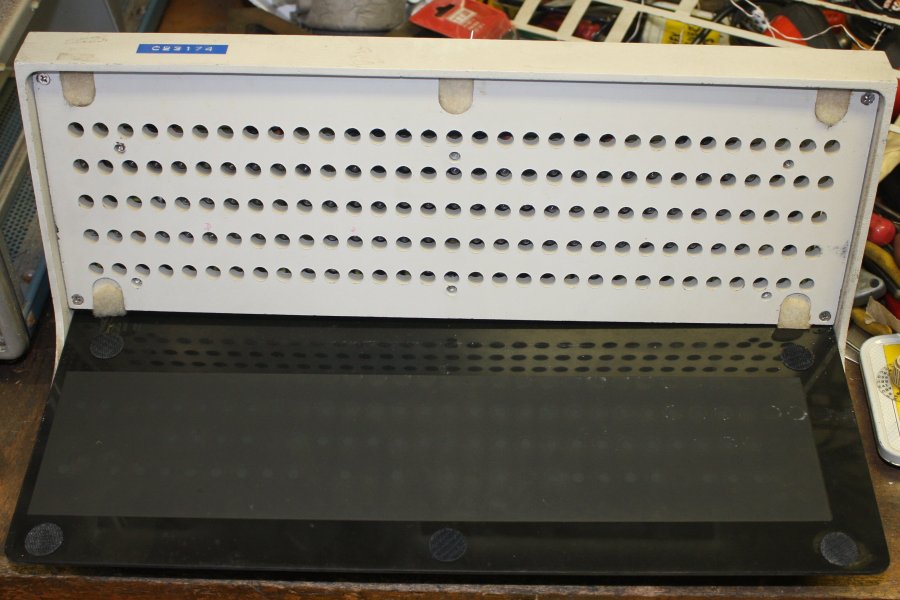
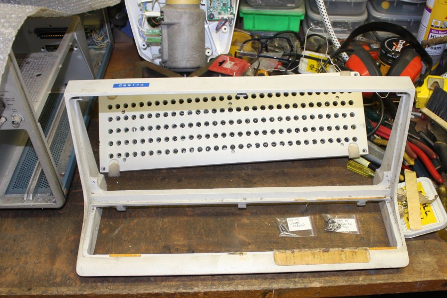
5. Behind the lights fascia, the substrate has holes for All The Lights. Nothing like retaining flexibility during early design stages.
 |
 |
 |
 |
 |
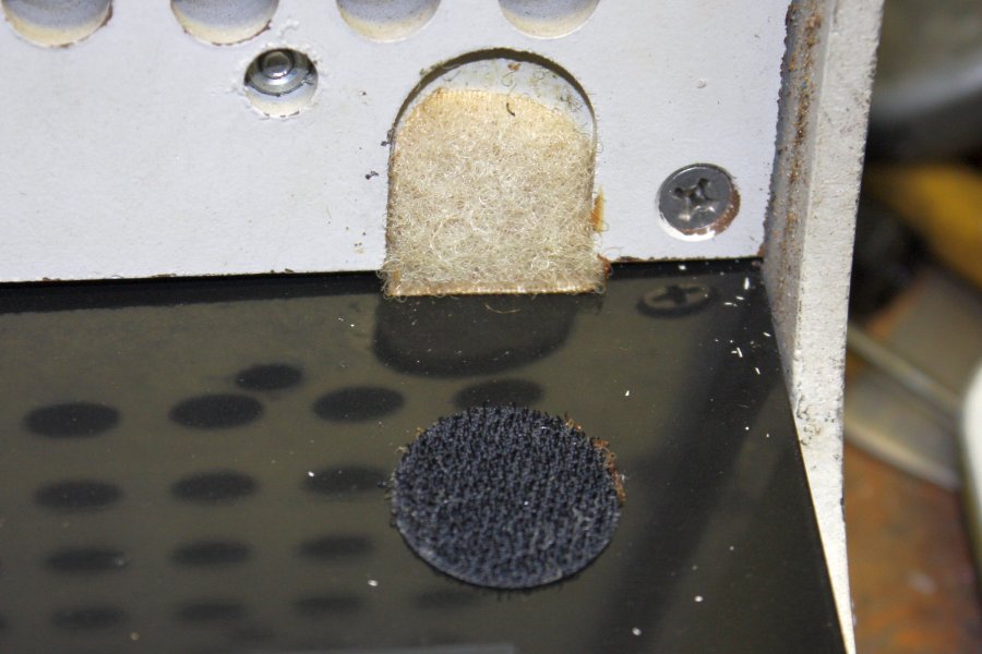
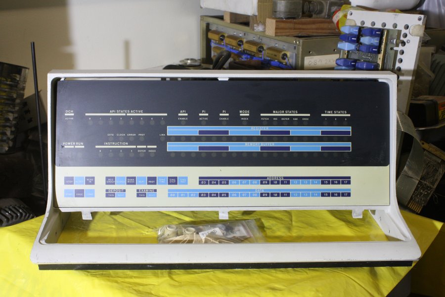
1. Unexpected. The lights fascia is held on with Velcro tabs. The PDP 15 was introduced in 1970, and I'm surprised to find Velcro was invented in 1941. So it was a common thing by 1970?
2. Holding the lights fascia up to a light.
3. The little light bulbs, nestling in their holes. It must have been a pain replacing these when they blew. I wonder what was this panel's MTBF?
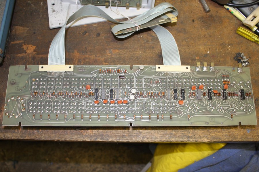
4. The back of the rocker switches PCB.
5. The back of the lights PCB. It seems that the rockers PCB cables plugged into a socket on the back of the lights PCB, and the cables from the lights PCB connected to the system. There don't seem to be enough traces on these flex cables for all the required signals, so presumably there is some multiplexing.
 |
 |
 |
 |
 |
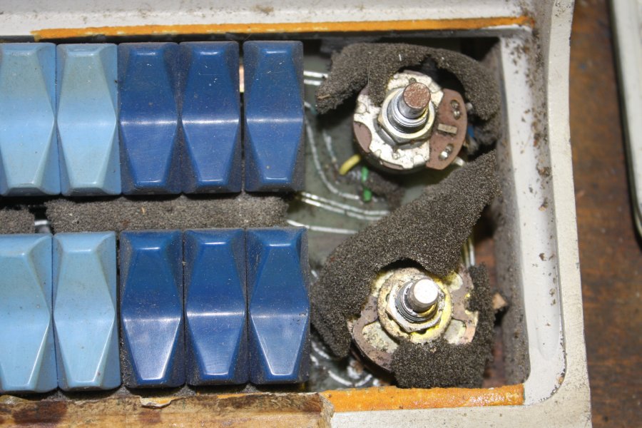
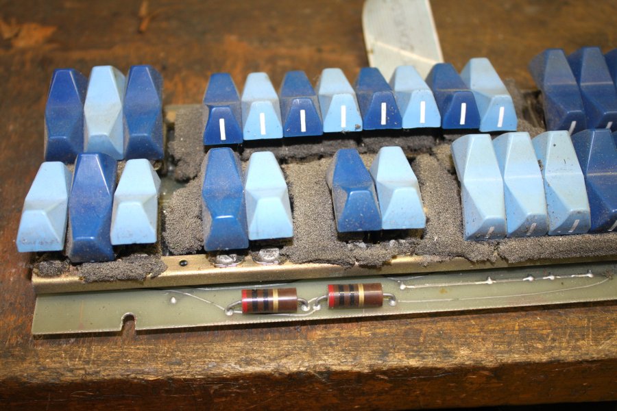
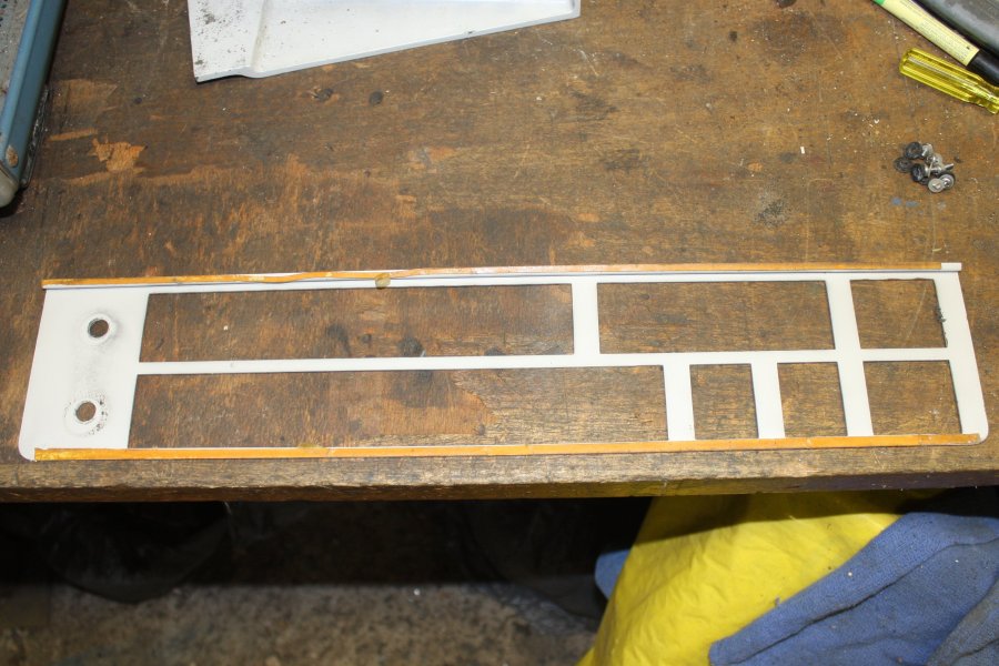
1, 2. Urethane foam, great. There used to be a dust-barrier sheet of foam behind the rockers fascia. But urethane foam inevitably decays to corrosive gunk. No wonder all the rocker movements feel 'sticky'.
Having the console rocker switches on a near horizontal surface, instead of the usual vertical front face of the machine, seems like a bizarre design choice. 'Someone had a bright idea' I suppose. I wonder if it came from the marketting department?
3. The ex-foam is so fragile it can be blown out with compressed air.
4. But the damage is done. All metal surfaces in contact with the foam are corroded to some degree. This presents a major chore, needing some consideration.
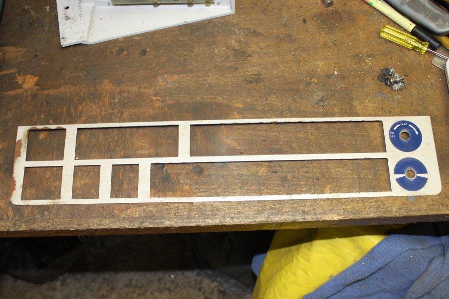
5. Another issue. What to do about the rusted areas of the rocker fascia? Can't repaint the whole thing, because of the detailing for the control knobs. (Later: Oh, obvious. Mask off the circles, repaint the rest.)
 |
 |
 |
 |
 |
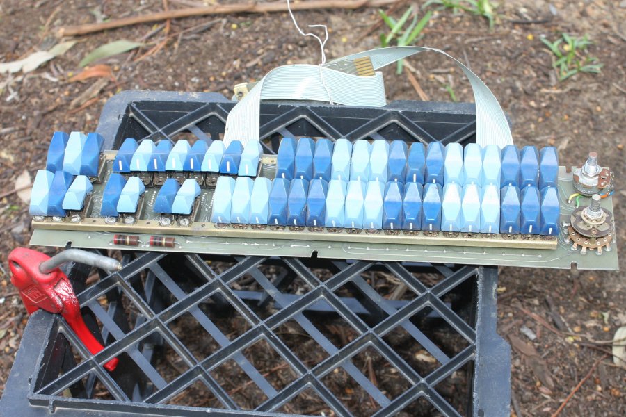
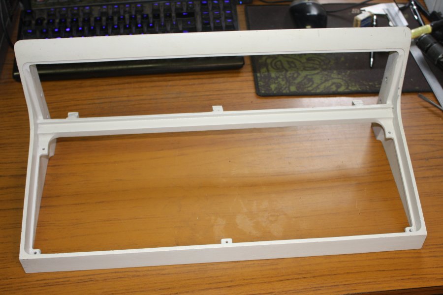
1. Ah, that's why this fascia felt floaty. It was only attached originally by narrow strips of double sided sticky tape. Long since separated. At least the remnants peel off easily. Considering the cost of these machines when new, a lot of the DEC mechanical design was quite sketchy.
2. The outer frame is diecast alloy, currently very dirty. The lights panel is molded plastic.
3. Giving the alloy frame a bath.
4. It cleaned up pretty nicely. The lights fascia too, though it has a few small scratches and scuffs.
5. All put aside out of the way, while I think about how to deal with the various issues.
Now my bench has some space again, so back to the oscilloscope.
 |
 |
 |
 |
 |
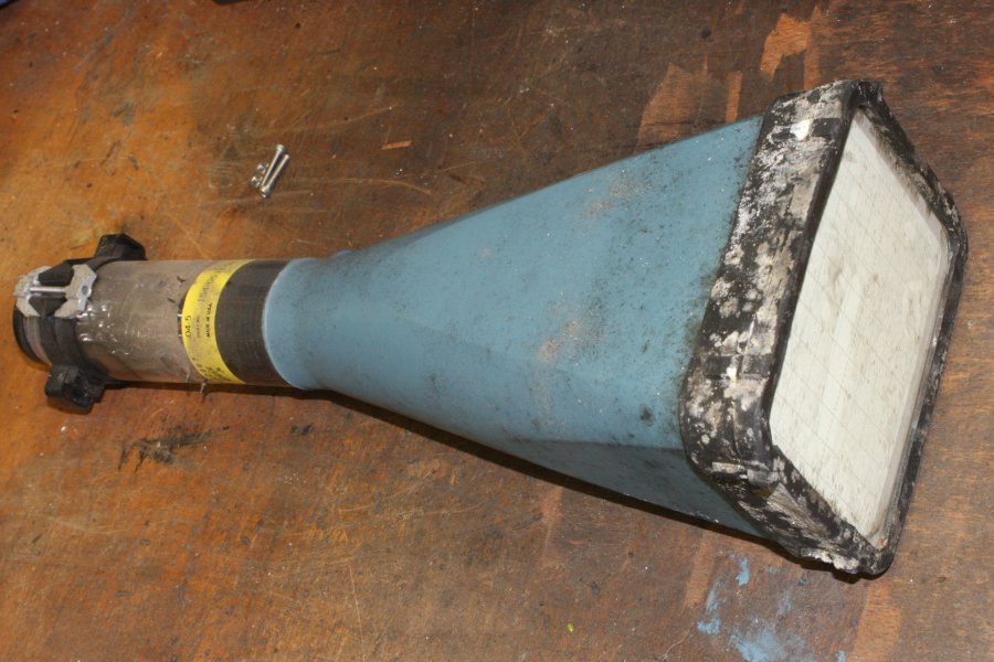
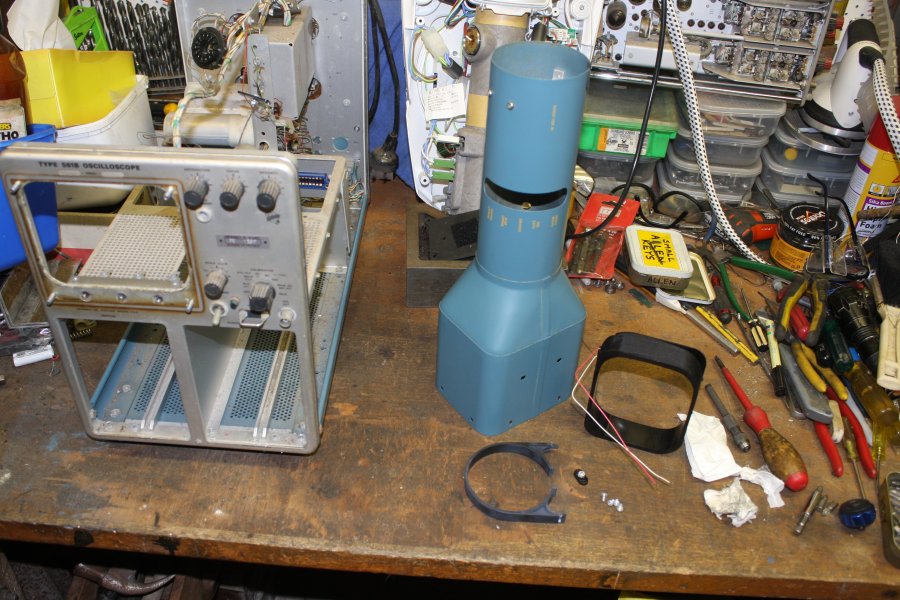
1, 2. The CRT slides out to the front, with the rubber surround attached. All very dirty. Turns out I undid the wrong screws to free it from the rear ring clamp — normally the black plastic ring on the tube neck should have stayed in the shielding can. It's going to be fiddly to reassemble this. Otoh, to clean everything this was best.
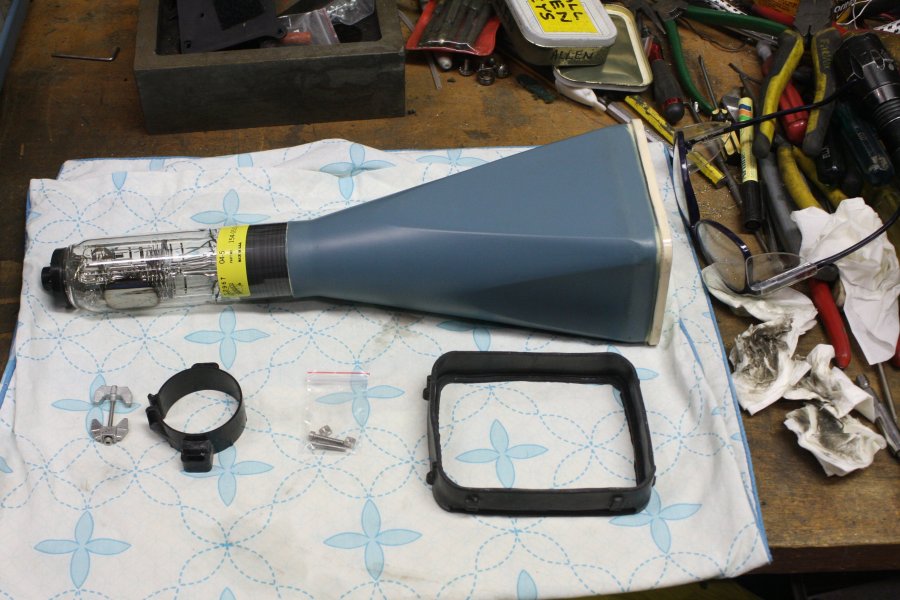
The tube must be handled very carefully. Apart from being an implosion risk and wise to always wear safety glasses while holding it out of the protective housing, there are four tiny metal pins through the sides of the thin glass neck. These are the contacts for the X and Y deflection plates, and they are especially delicate. Bending them at all could break the vacuum seal and destroy the tube. I use bare hands — gloves increase clumsiness risk too much. Also bare hands on a large glass vacuum device keeps you alert. Never place the tube on a hard surface, as grains of dirt can scratch the glass. Hence the soft cloth. Extra crucial if resting it on the flat faceplate, but then I would never stand it upright like that. Too much risk of knocking it over.
3. Cleaned. The rubber is still in good condition, once the mold/sulfur bloom is scrubbed off.
4. The shield can, trace rotation coil, etc, also removed and cleaned.
5. The fascia. Brown staining from the rubber, and some corrosion on the rear due to long exposure to damp.
 |
 |
 |
 |
 |
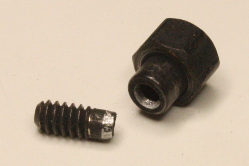
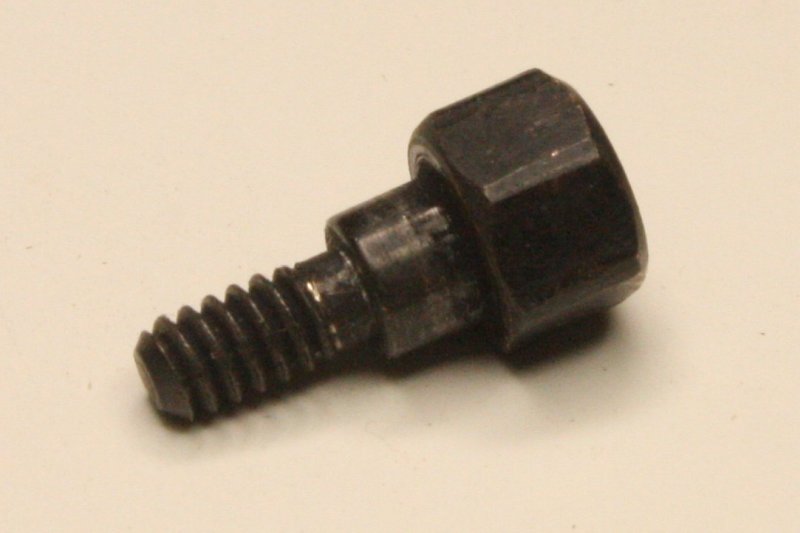
1. Of all the screws for the base plate, side extrusions and feet (about 22) naturally it's the very last one that is seized. Whether due to damp, or just chemical decay of the plastic feet, there is considerable corrosion of all metal in contact with the feet. The three other feet have screws with accessible nuts on the other side of the extrusion, so those could be loosened with a spanner. But due to lack of space the foot adjacent to the transformer uses nutserts fixed in the extrusions. One of the screws came out (upon application of considerable force) but the last one would not budge. The phillips head cross rounded out. Cutting a slot in the head with a hacksaw, still wasn't enough. That rounded out too.
2. Even after drilling the head completely off the screw, the foot still couldn't be levered loose. It only came off after drilling out some of the screw shaft too. The feet have molded-in metal ferrules around the securing screws, and this screw's corrosion had locked it solidly in its ferrule.
3. Urrgh, those feet. Maybe they will clean up OK, or maybe I'll have to make new ones somehow. Good incentive to get the 3D printer going finally.
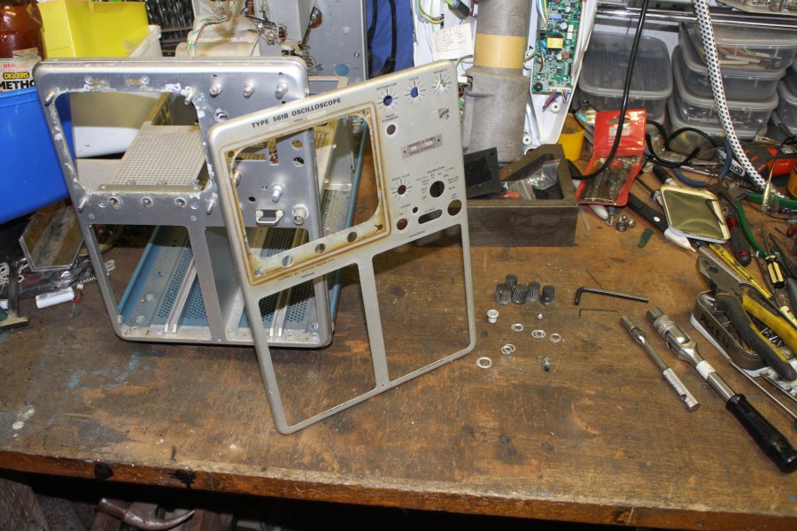
4. The scope front face cleaned up fairly well.
5. All the front panel and base mounting hardware. Most of the screws are those mushroom heads again, that I recently bought in stainless. The longer ones are easy to replace too.
 | 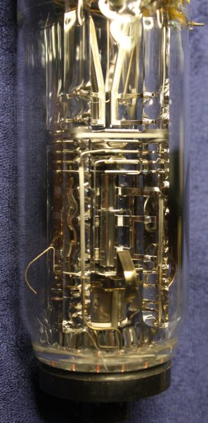 |
1. Air leakage, loss of vacuum. This tube has no sign of the Getter oxidizing, so the vacuum is good.
2. Burned phosphor. This one shows no visible burn-in.
3. Heater filament failure. The only ways to test that are to try running it, or measure filament resistance.
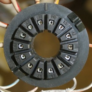
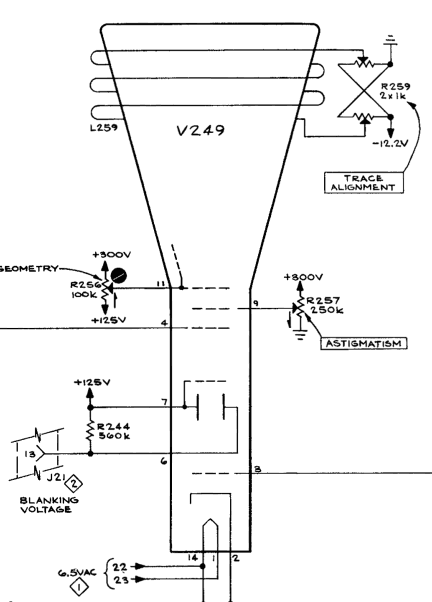
The schematic shows the filament pins are numbers 1 and 14. The socket shows there are 14 pins, with 1 and 14 on either side of the locating slot. Or on the tube base, either side of the locating ridge. Easy.
Measuring resistance with a multimeter, the filament is 2.4 ohms. (It would increase in resistance when hot.)
Excellent! That dismisses my biggest worry with this scope. Pretty much every other possible fault should be repairable, cheaply, but a dead CRT would be a show stopper. (Fingers crossed about a few unobtainium old semiconductors in the plugin modules.)
Incidentally, to state the obvious only because it may not be known by some with knowledge only of semiconductor electronics, the filament in vacuum tubes is required to heat the cathode up to red heat. This boosts electron emission from the cathode surface into the surrounding vacuum, and hence the flow of electrons into the rest of the tube's structures. No hot cathode, no vacuum tube function at all. The filaments are delicate, and can fracture or burn out. One other potential problem is that a special coating is usually placed on the cathode to assist electron emission, and this can become worn out. But that's a 'reduced function' problem not usually a total failure as with a dead filament. There are other types of internal faults possible as well, but uncommon. We'll see.
 |
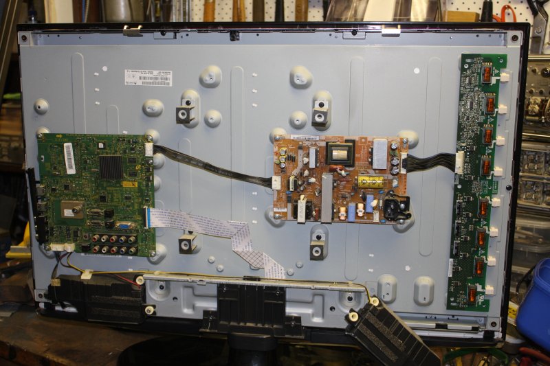 |
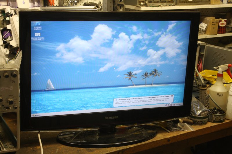
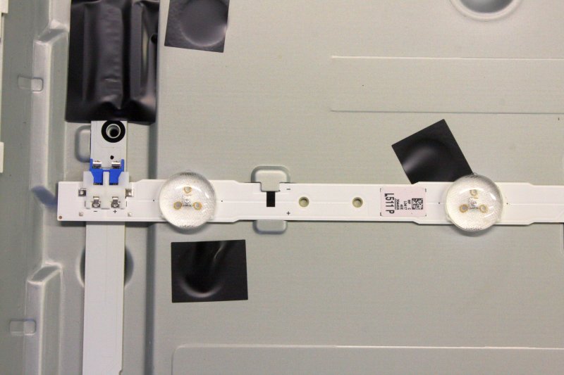
Recently I pick up discarded LCD TVs looking for ones with LED backlighting, for a side project. This one has fluro-backlighting (PCB at right in the pic with the rear cover removed), so I could either trash it for the few useful components on the power supply board, or use it as a monitor. I think I'll keep it.
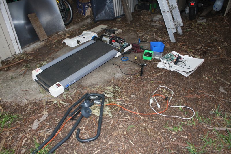
Another type of consumer appliance commonly street tossed, is exercise treadmills. I guess people buy these in the hope of losing weight, but apparently lose motivation quickly and end up throwing it out. Personally I'd rather just go for a run somewhere interesting. Anyway a lot end up on the kerb, sometimes looking very little used. They have a powerful motor with speed controller, and often also a grunty linear actuator for setting the treadmill slope. I sometimes grab these as I'm looking for one with specific features for another side project. (Hint: what's the core element of a Van de Graaff generator?)
 |
 |
 |
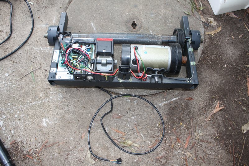 |
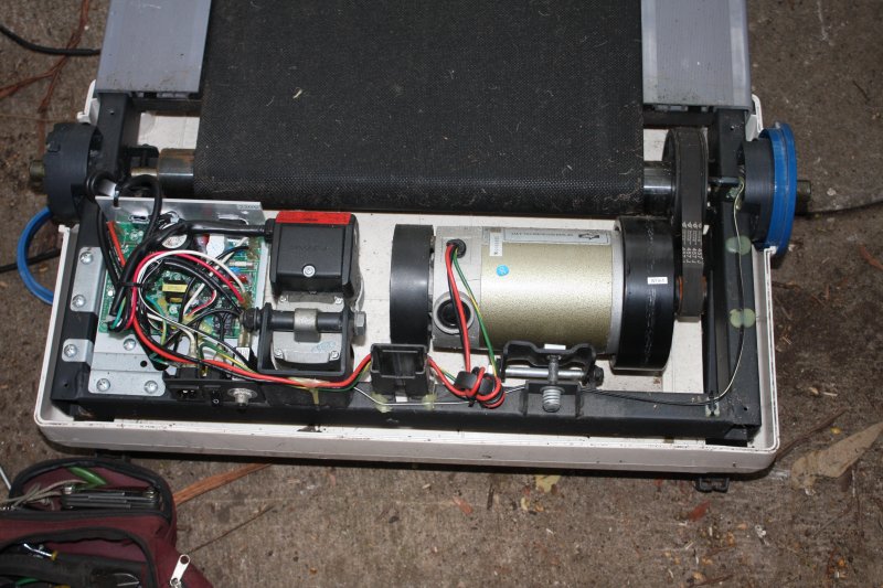
For what I want, the structure is ideal. Still to determine: whether the motor controller can be easily coaxed to run.
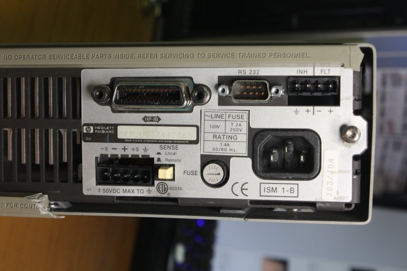
Back on 5th Feb, I'd bought an instrument on ebay, a HP 66312A 'Dynamic Measurement DC Source.' It's basically a power supply, but with agile output configuration and logging of power consumption in the load. I'd thought it might go cheaply, and won it with a snipe bid for US $21.50. One shipping option was to have it sent direct to me in Australia via ebay's 'Global Shipping Program', GSP. It seemed the shipping cost that way would be about the same as to send it to my reshipper in Califronia, then on to me in Australia. Don't think I've used GSP before, so gave it a try.
 |
 |
 |
 |
 |
 |
 |
 |
 |
 |
 |
 |
 |
 |
 |
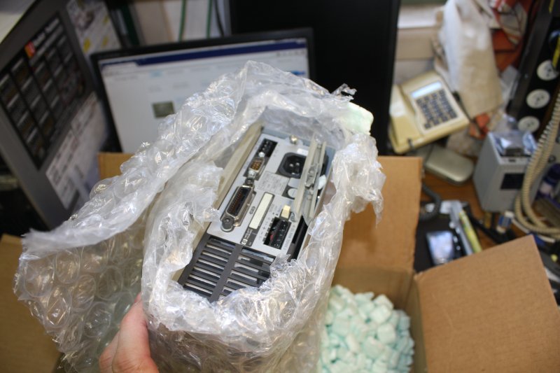
I wish I hadn't. GSP apparently stands for Global Smashing Program.
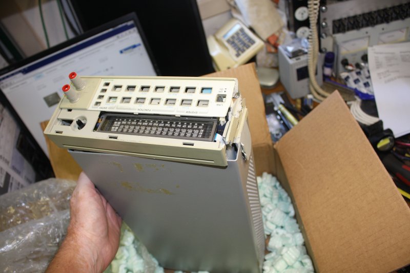
Two things went wrong here. Firstly the seller packed it with virtually zero padding between the front and rear faces of the instrument and the box. Just one layer of bubble wrap for a weight of 9.2Kg (20.3 lb); laughable!
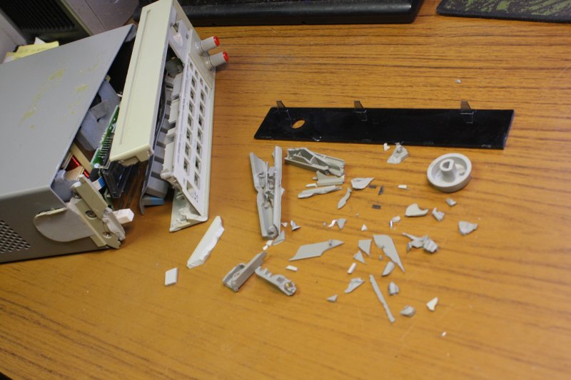
Then somewhere on the GSP way, the box was dropped heavily, at least twice, on edges. Resulting in badly smashed plastic front and rear moldings, and bent metalwork.
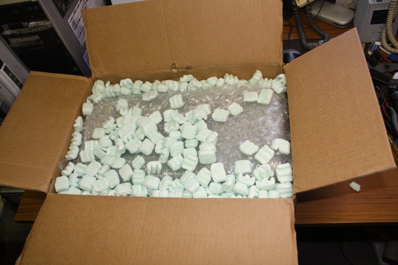
Amazingly, the electronics still works. Supposedly I'll receive a total refund from ebay (item plus shipping), which means I get a free plastic fragments jig saw puzzle. I'll see if I can fit and glue the fragments back together. It won't be pretty, but for free, I can't complain.
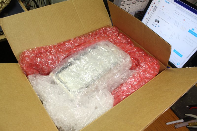
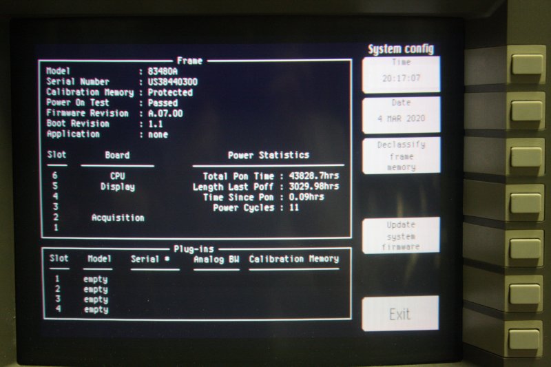
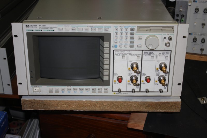
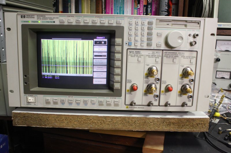
In contrast here's bubble wrap done right. This is a box via ebay containing a module extender for the HP 83480A digital communications Analyzer (a 50 GHz oscilloscope, see my 2014 article.) It needed some cleaning and maintenance, but there was no shipping damage.
 |
 |
 |
At breakfast in the morning, from 7:15am to 7:19am a series of SMS arrived, alerting to fraudulent transactions on my card. Culminating in an attempt to withdraw $1500. I logged into my bank account, find a list of new withdrawals that are definitely fraudulent. Phoned the bank, they see it happening too, we cancelled the card. Supposedly those transactions will all be reversed. There went a few hours.
Then while doing some data preparation for a specialist appointment at midday, in the last stage before leaving I deleted a folder on a thumb drive one level higher than I meant to. A bit distracted due to the card fraud and topic of discussion with the specialist.
Result: 15 minutes to copy it all back on there, and being a bit late to the appointment. Turned out it didn't matter, he was running behind with other patients anyway.
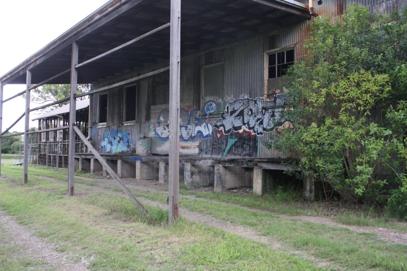
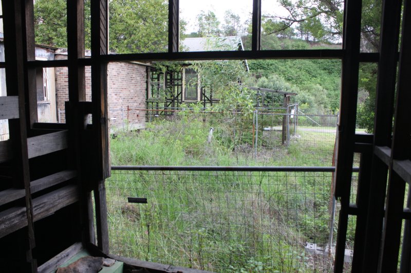
Driving home at 2pm, there's an interesting old abandoned building I've driven past many times but always had no time to spare. This afternoon was free, so I stopped to have a look. It's cool, but I hadn't brought a camera today. Walking to it I'd passed through some open bush.
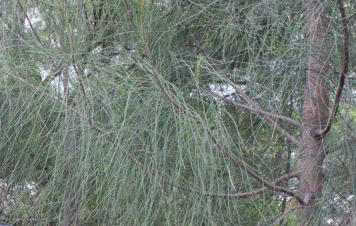 Australia has a tree called Casuarina, that have long, soft needle leaves. Wind blowing through Casuarina stands makes a lovely sighing sound, and the leaves feel nice on your skin as you brush past them. I like these trees particularly.
Today one of the leaves brushed against my open left eye, and the end slid up under the eyelid a bit. They are so soft it didn't actually hurt, and within a few minutes I could hardly tell it had happened. Continued on with the enjoyable abandonment exploration. (I returned later with a camera, so you'll see pics.)
Turns out Casuarinas are another Australian species that's trying to kill or maim you. Who knew?
Continuing homeward, I got to the bank in time to draw out some cash for the weekend. (No card, and the specialist's fee had cleaned me out.) Arrived home a few minutes to five, to find a 'parcel at the post office' notice. Drive, park, run flat out, and made it to the post office just as they were preparing to close. So I don't have to wait till next Monday, phew.
It's from Shenzhen China, and given the slowness of cheap post from China there's no real risk of nCoV contagion. Certainly none compared to the risks due to our gov not shutting down international air travel into Australia yet.
 |
 |
 |
 |
 |
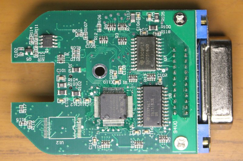 |
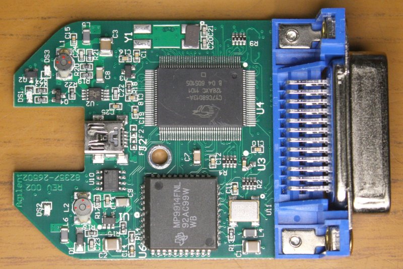
 |
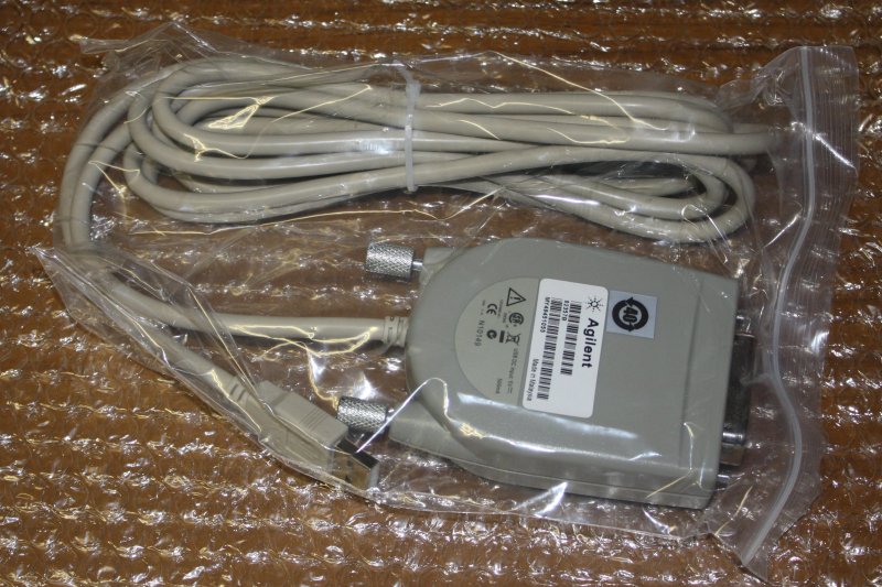
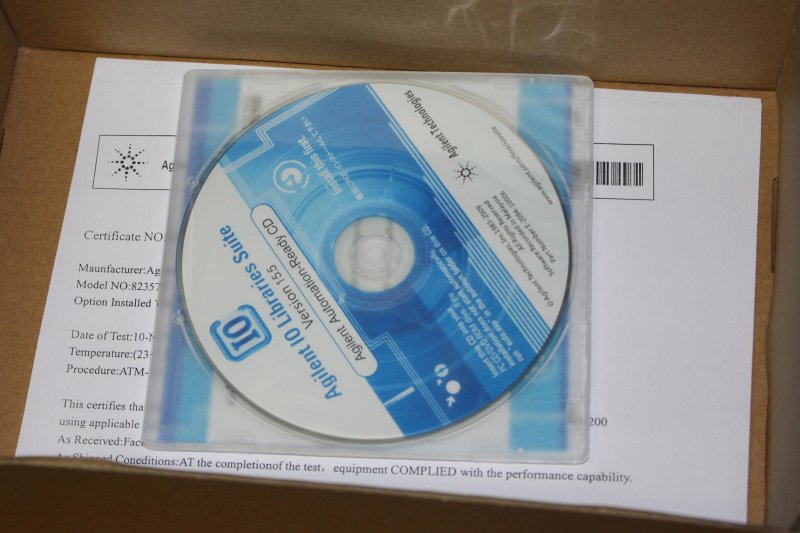
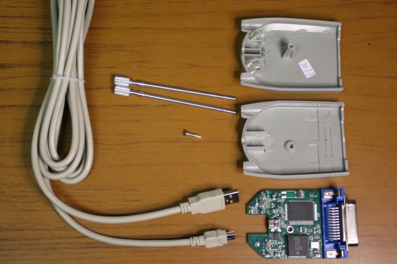
For one thing the price; US $80. The real thing is something like ten times that price — I didn't even look up the exact genuine Agilent price since it's guaranteed to be ridiculous and beyond my range.
There's a thread about these clones on eevblog and as expected this one is a clone. So long as it works...
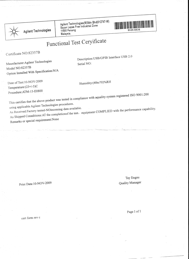
The mystery is, since they went to so much trouble to make the packaging, the unit and software CD look genuine, what is it with the one sheet, badly photocopied "Functional Test Ceryificate"? Is this some kind of deliberate taunt directed at Agilent? A visual pun on 'slant'? Inscrutable.
By the time I'd had a quick look at that it was 6:30pm, and my left eye was starting to get sore. By 8pm the eye was agonizing but too late to go to a doctor. I tried finding an after-hours home visit GP, no luck. Attempted to rinse the eye, thinking maybe there was a broken-off bit of the needle leaf up under the eyelid. But lacking something like an industrial eye flush station that didn't achieve anything.
Hospitals suck, and going to casualty involves a certainty of hours of waiting and inaction. (What can you expect for free service?) No choices left, I drove to the local hospital about 10:30pm. Ha, Bankstown hospital Casualty intake area is being renovated, and they are currently using a small improvised space. The real one won't be completed until early 2021 they say. What great timing for the inevitable nCoV epidemic in the next few months. But anyway...
Several hours of sitting there in near screaming pain, among others in varying degrees of pain and distress. Passed like a moment — not really. Around 2am they got around to providing eye anesthesia and antibiotic drops. Big improvement. A later attempt to physically examine for any foreign body up under the eyelid failed to find anything. But by then the drops were settling it down somewhat. I wasn't discharged from the hospital till 4am. Given more of the drops to self-administer. Drove home.
Saturday was a write off. Eye improving but still too sore to do anything much. Mostly dozed. By the evening it was almost ignorable again, by Sunday it was better.
What was that? Either an infection from bacteria on the leaf, or some kind of allergic reaction to dust/pollen on the leaf surface. Note to self: avoid Casuarina needles contact with eyes.
High point of the whole evening: I'd got the absolutely closest free street parking spot. Just across the road from the hospital entrance. As opposed to somewhere several blocks away as usual even at night.
I needed to go to my daughter's place in Ashfield, to do a chore for her. This meant I'd be passing that abandoned building again so this time I took my camera. Walked among my friends the Casuarinas again, more carefully.
 |
 |
 |
 |
 |
 |
 |
 |
 |
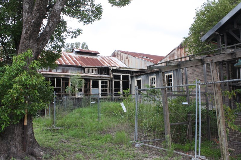 |
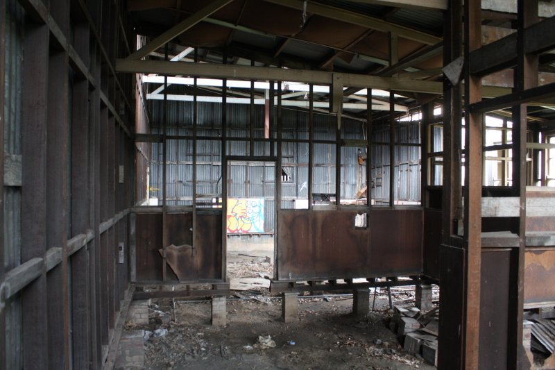
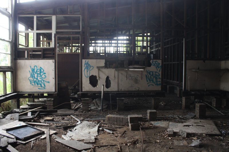
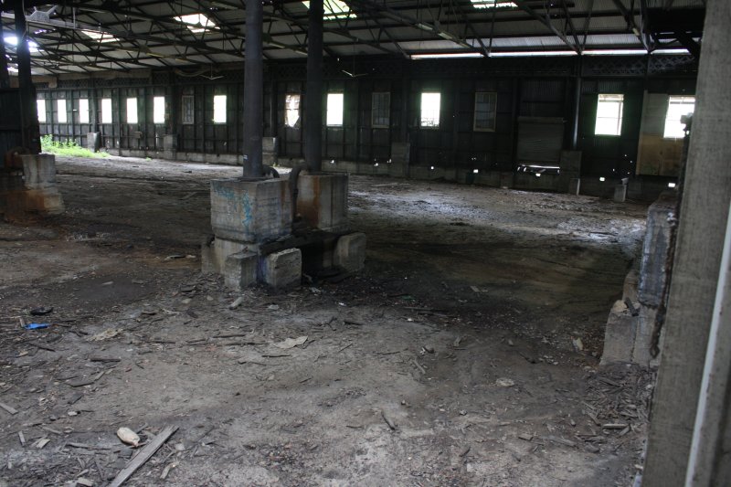
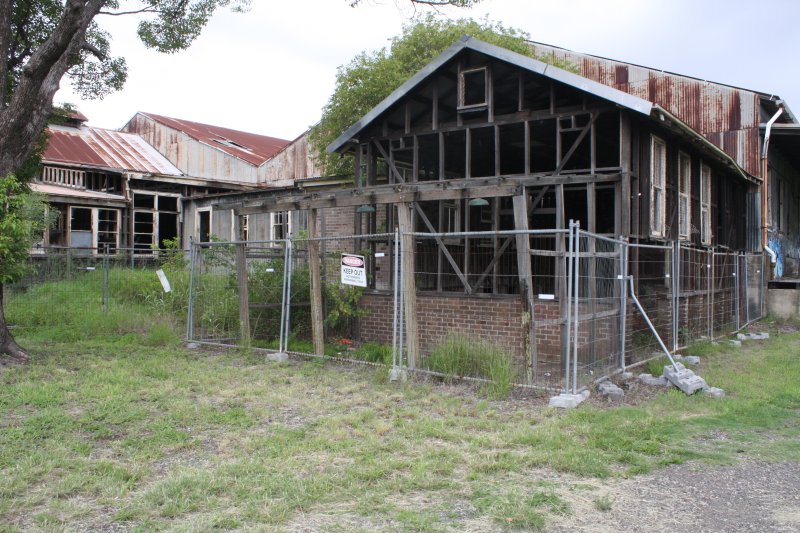
A fine example of the essentially bipolar psychosis of government bureaucracy. The structure is Heritage Listed as historically significant. So it can't be knocked down for site redevelopment. On the other hand a lot of the wall cladding was old fibro, which is considered an asbestos hazard. So that had to be 'remediated', ie the cladding smashed to pieces, exposing the bare timber to weathering. Also the floor was timber, and presumably had a few rotten spots. Whether that was deemed a falling or fire hazard, who knows. In any case all the timber floors and support pilars have been ripped out.
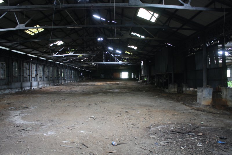
 So now it's just a huge rusting, rotting empty shell, with plenty of holes in the roof and the vast sloping dirt floor evolving into a landscape of eroding water channels and mud lakes. Making a mockery of the concept of 'preservation.'
But it's very atmospheric.
← Ironically, lying in the mud I found an unopened Tyvek 'sperm suit' pack. In the right size.
Flowing water had washed silt into the packet a little, but after drying at home it all cleaned off and the suit is undamaged. Well, I suspect that just might come in handy sometime in the next few months. Thanks, poor old dying building. One last good deed? I do appreciate it.
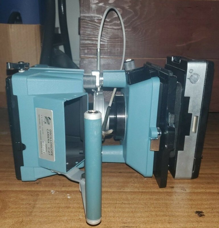
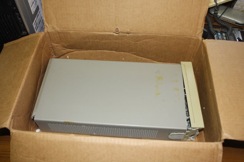
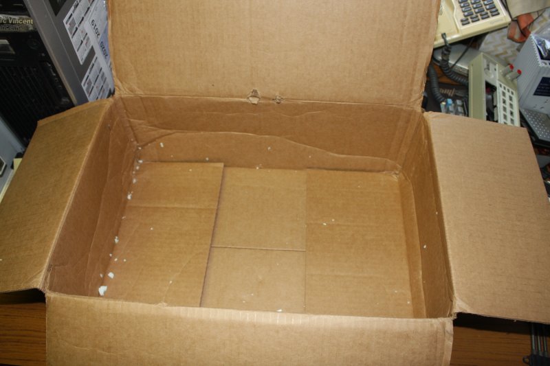
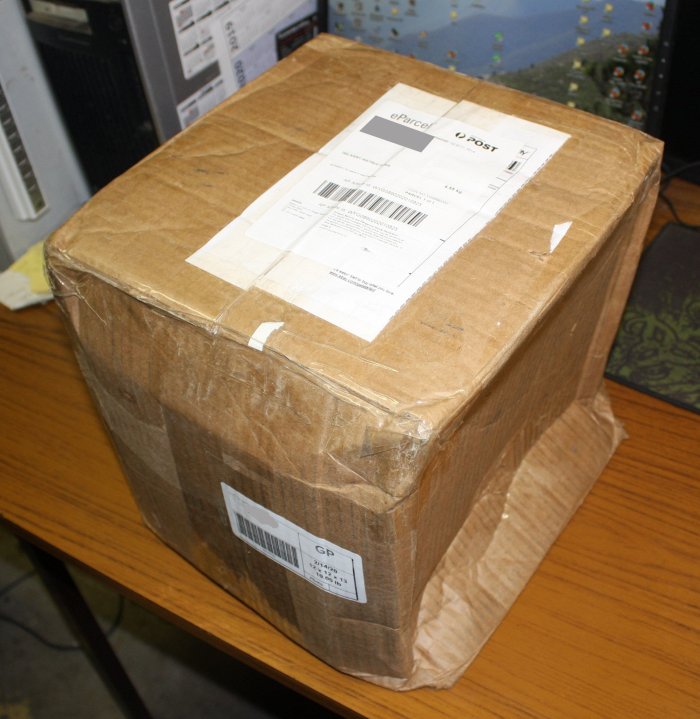
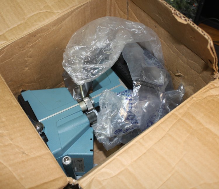
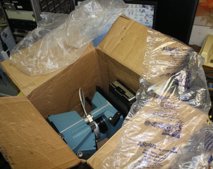
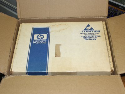
That C-27 camera I'd won for 99 cents arrived, along with another ebay item. Seeing the box the camera arrived in made me groan, expecting this would be another smashed priceless relic. Lifting it, felt like a large heavy object completely loose inside, with zero padding. Oh no...
 |
 |
 |
 |
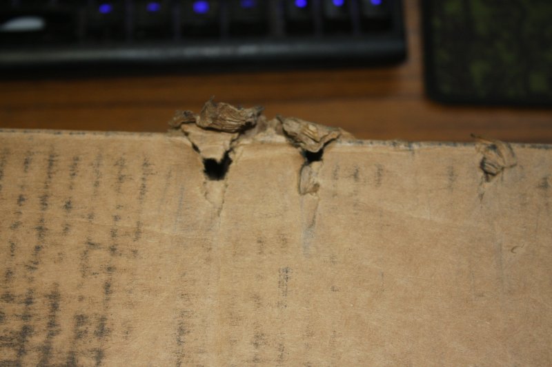
Before you say "well you only paid 99 cents", yes but I also paid for pack and post. Regardless of how he felt about the item price, he had a duty to pack properly, to protect against damage in shipping. This is a miserably incompetent job.
Spite maybe? Anyone who'd willfully set up this lovely piece of history for destruction, deserves to die painfully.
 |
 |
 |
 |
 |
 |
 |
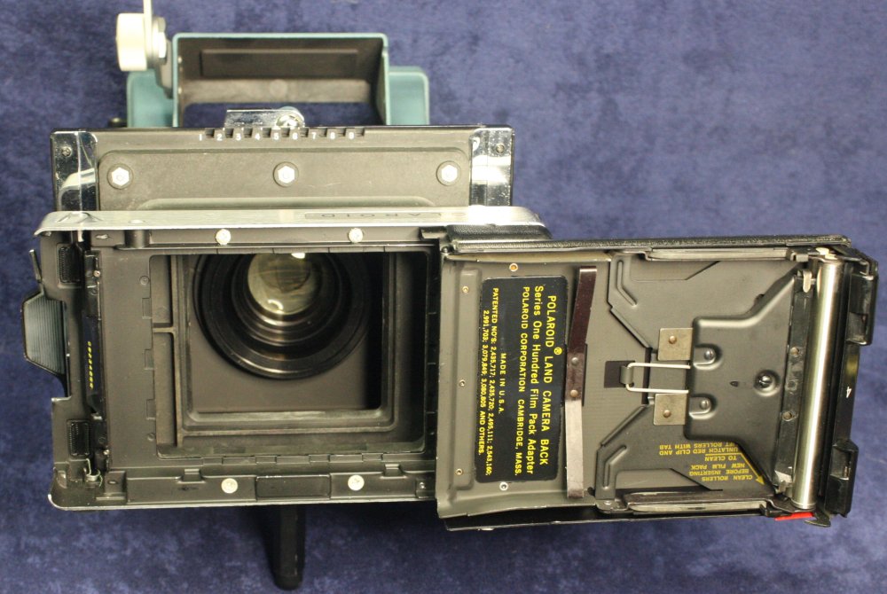 |
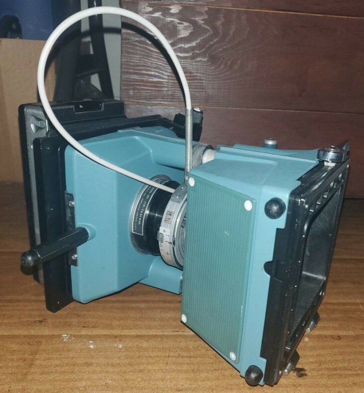
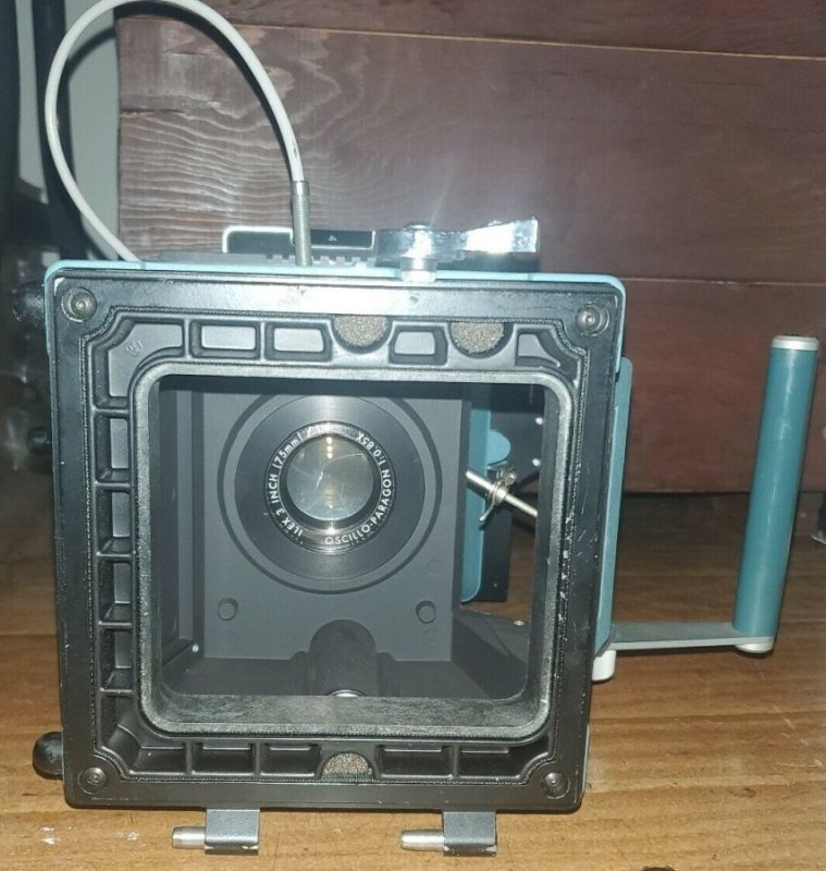
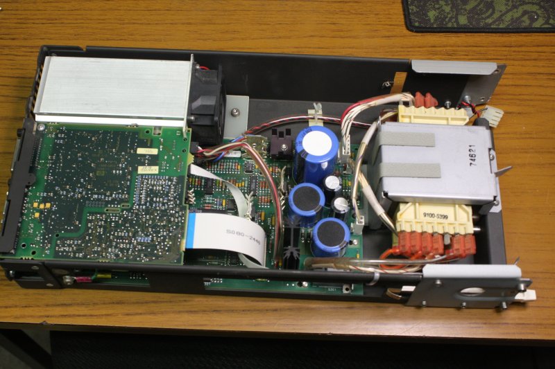
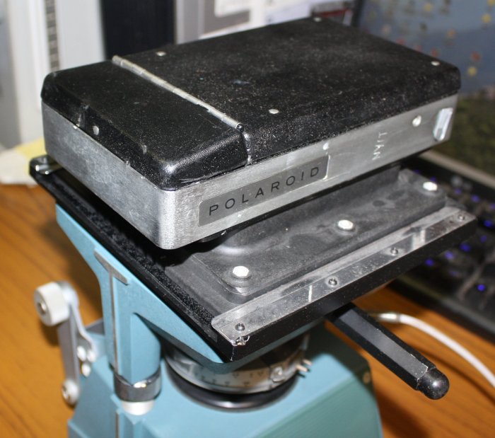
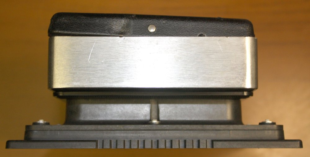
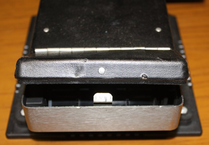
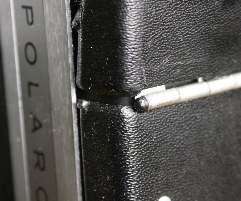
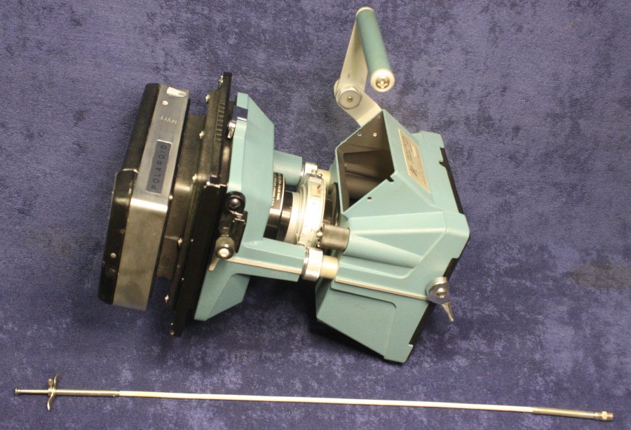
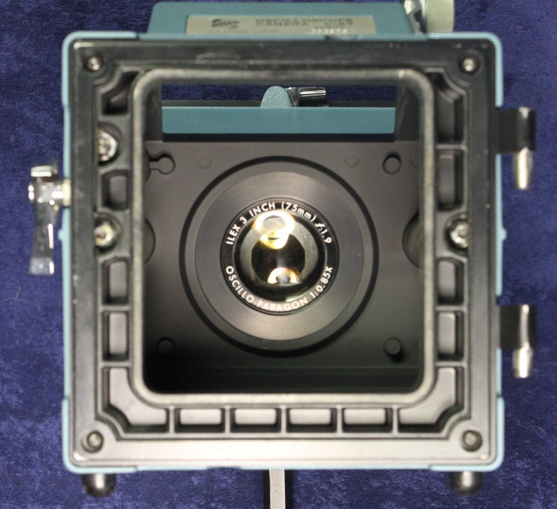
There is supposed to be a rubber 'viewing hood' that is entirely missing, probably perished and removed long ago. But overall it's in excellent condition. No corrosion, the iris and shutter work fine, the lens glass is pristine. It fits the scope bezel.
But best of all, to my surprise it seems that a Japanese company some years ago took up production of Polaroid film packs! It remains to be seen if that includes "Series One Hundred" film packs that suit this camera. I hope so.
Yes, it's true, using a modern digital scope to save a screen image to memory with the touch of a button is a lot more convenient. On the other hand, have you ever seen photographic images of an old analog scope phosphor screen with filament bulb illuminated graticule? You cannot tell me the result is not beautiful, in a way no digital scope can ever achieve.
If by chance I were to ever achieve some significant research result, I would want the first success recorded with this. History...
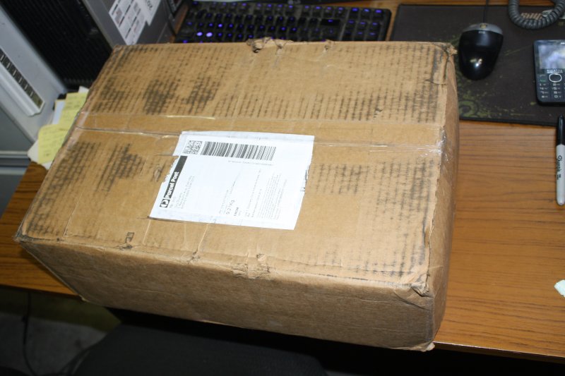
Speaking of history, a piece of it arrived in the other box Monday morning. In this instance the original box was also a relic, so I'd asked the seller to outer-box it for protection. Hence it came like this →
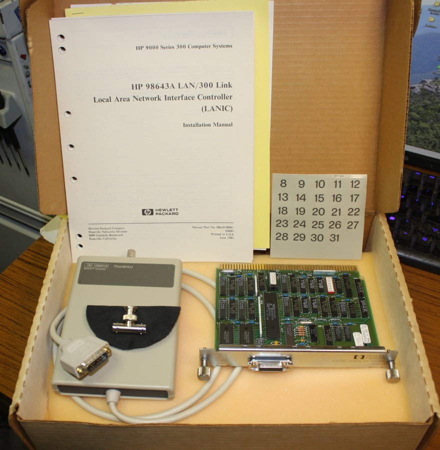 |
The card has an AUI interface and there's a 10BASE2 MAU in the box. 10BASE2 is 'thinnet', using RG58 coaxial cable.
As opposed to 'thicknet/10BASE5', the original ethernet implementation that used much thicker coax and very bulky cable taps.
In the history of ethernet evolution, this would have been very soon after the appearance of 10BASE2 networks.
Mainly though, I want to see if I can use it to get a HP 9000 system talking to a modern PC via a LAN. Maybe... I have two, a HP 9000-226, and a HP 9000-300(dual height chassis) both being restored currently. Also have plenty of 10BASE-T MAUs, which will work with this card.
Oh, and yes, the manual for the card does include full schematics and parts list. Not something you'd ever see today.
Way back in 2014 I bought a HP 83480A scope mainframe, without plugins. It was pretty cheap at US $112, and appeared to be a means to obtain high frequency optical signal sampling (which I need for a project.) So without much investigation I bought it. I'd expected to buy some optical/electrical sampling plugins fairly quickly, assuming they'd be in similar price range.
Oops! Turns out the plugins are still compatible with current high-end Agilent/whatever-their-name-is-now, and hence are ebay-priced in the thousands. Every now and then I check prices, and there's not been any significant decline.
So the scope frame has sat under a dust cover in storage ever since.
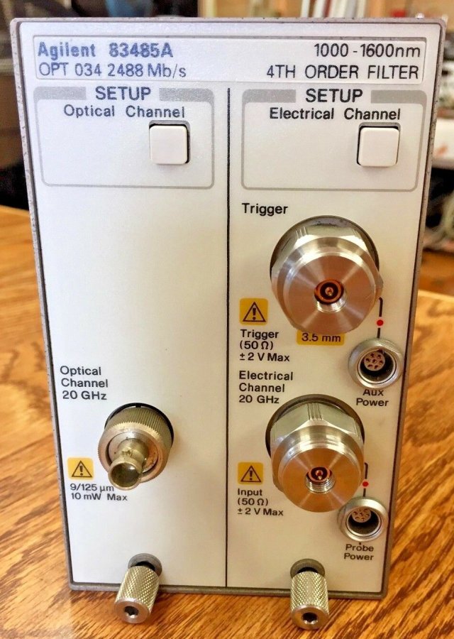
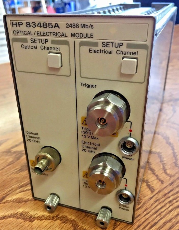
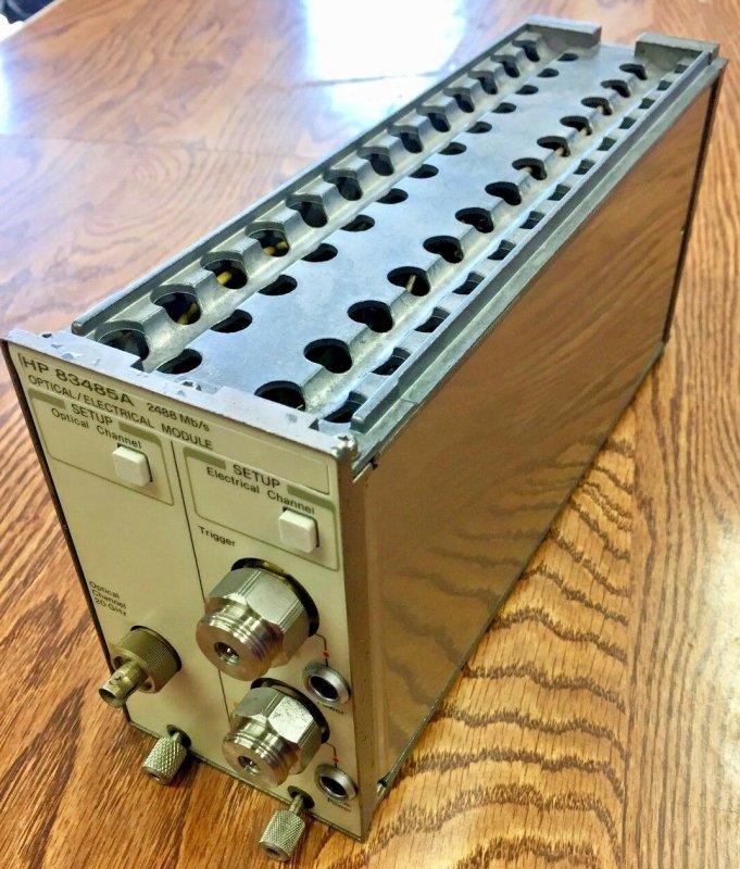
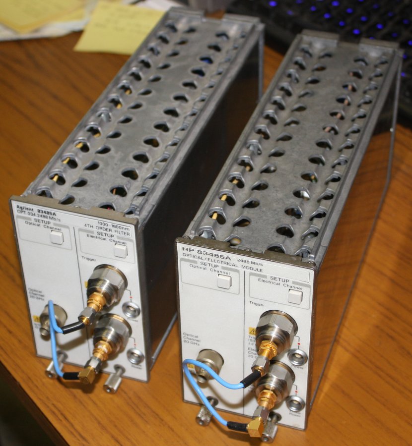
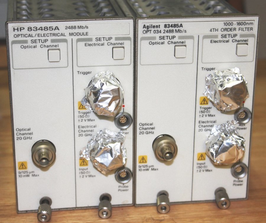
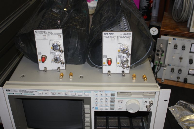
Till now. The modules I wanted (HP 83482A : 30 GHz integrated optical channel and 40 GHz electrical channel) are still up in the thousands. My second choice (HP 83485A : 20 GHz integrated optical channel, and 20 GHz electrical channel) are usually pricey too. But a couple came up closer to my range. After some bargaining, I got two for US $450 each. The pair are exactly the same functionally, except produced before and after the company changed name from HP to Agilent. On the printed fascia more text than just the logo changed, so they look a little different. No matter.
If they work, I'll be very grateful for the low price. Some of the seller's photos:
 |
 |
 |
 |
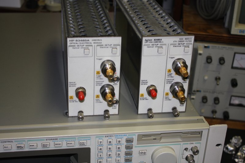
It's interesting that almost always, when such modules are listed on ebay they are missing the essential APC 3.5 f-f gold plated port-savers, and SMA shorting or 50 ohm terminator caps. Which shows that the sellers have little understanding of what they are selling, because these inputs are rated +-2V MAX, and this is not a joke. Reading the manuals, the absolutely required anti-static measures are extreme. For instance rigorously shorting the internal conductor of coax to the shield, and both to the module frame, before connecting the cable to the port. Coax cable is a capacitor, and the core wire can accumulate enough charge to kill these delicate ports.
I've seen an input port of this type get static-blown by some fool (my boss at the time) casually touching it, and it cost multiple thousands and a long delay to get it repaired.
APC 3.5mm static-sensitive ports should look like this at all times when not actually in use →
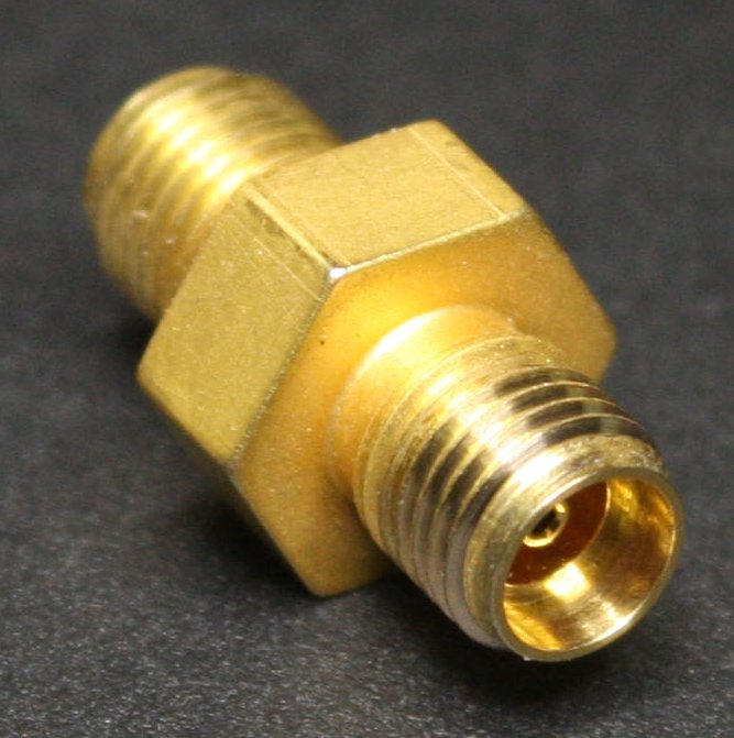 |
Take a guess how much these cost new.
Not actually much gold in them, just thinly plated. But the plating inside and on the connecting end faces is electrically critical.
 ← This is a typical ebay listing.
Why are the port-savers almost always missing on ebay units? Yet the prices are still thousands, as if the units are 'known good' - which without static protection on the ports, they are absolutely NOT.
Maybe the companies sending these units to surplus might retain the port protectors since they are universal and can be reused with new equipment? Sounds sensible, but otoh why would anyone 'dispose' of working modules at all?
Perhaps in addition some ebay sellers think "oooh, pretty gold connector, I can sell that separately." So they remove them, very possibly static zapping the input in the process.
Besides the electrostatic damage risks, few in the surplus equipment handling chain will be aware of how easily these APC connectors are physically damaged by mishandling. One thing to never, ever do is rotate the mated connector. This can spall the precision gold plated mating surfaces. Instead one must rotate only the outer stainless steel nut, while holding the inserted connector motionless apart from being pulled carefully inwards or outwards. Also the nut must be torqued to a precise, quite light tightness, never more. But everyone not knowing the correct proceedure will just instinctively screw in the connector till it's tight. Which likely damages the precious, delicate, precision port surface planes.
Another thing to never do, is insert an SMA connector into the APC 3.5 port on the sampler. They do fit, but SMA have looser tolerances in every respect, and can (likely) degrade the APC 3.5 connector. Hence the use of sacrificial APC 3.5 female to female 'protectors' in these ports. One end only ever touches the port's APC 3.5 and just stays there. The other end gets SMAs attached. Once it's become worn, it's replaced. Using SMA connectors directly is another big trap for casuals. The ports look like SMA standard, and an SMA connector feels like it fits fine. But it's a disaster. Plus anyone making this mistake probably doesn't know about the 'discharge the cables, or else' trap.
Anyway, this seller's modules were minus the APC 3.5 and shorting cap. Typical. Which means they might be blown. I explained the static issue to the seller and asked if he could please wrap some al-foil over the ports, for shipping. The modules would be handled by staff at my US reshipper, and they of course can't be expected to understand the static damage risks with exposed APC ports.
So what did he do? He very kindly made an extra effort while preparing to pack and ship. He found some spare SMA hardware and screwed SMA bulkhead f-f connectors into all four ports. Then 'anti-static closed' them with short SMA cables; floating and possibly charged center conductor and all. Did he discharge them first? Don't know.
Sigh. By the time he sent me photos it was too late, done and posted. I sent him a page from the manual about care and handling of APC 3.5 connector ports, so maybe in future he'll know. I should have done that initially, but didn't because I just assumed he'd follow my suggestion to wrap the ports with al-foil. Which would have been static-safe because he'd be holding the module body in the other hand.
He's a nice guy, trying to be helpful. This is just an example of the mishandling most of these modules will have from typical ebay sellers since the hazards are so esoteric and unobvious. Buyer beware.
 |
 |
Here they are, with their heart-attack inducing 'helpful protection' on the ports.
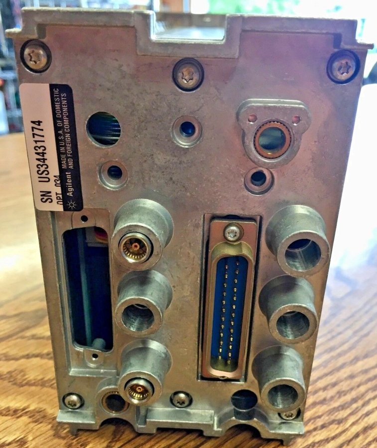
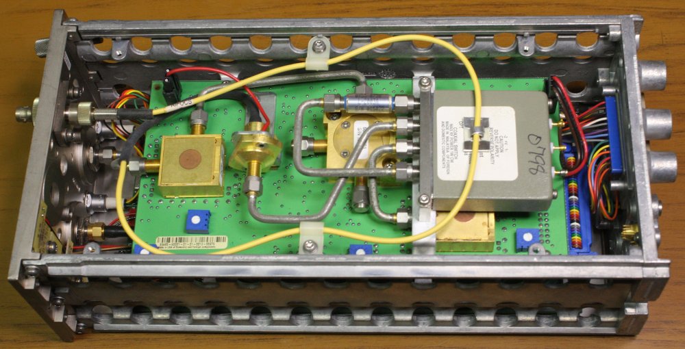
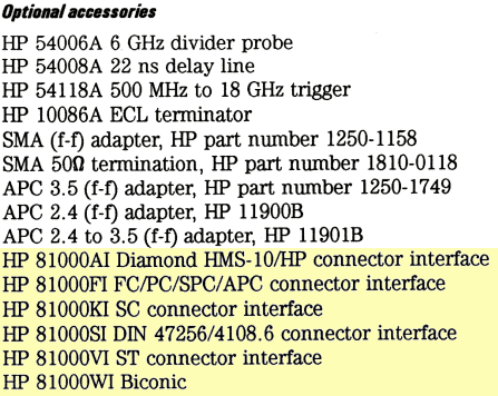
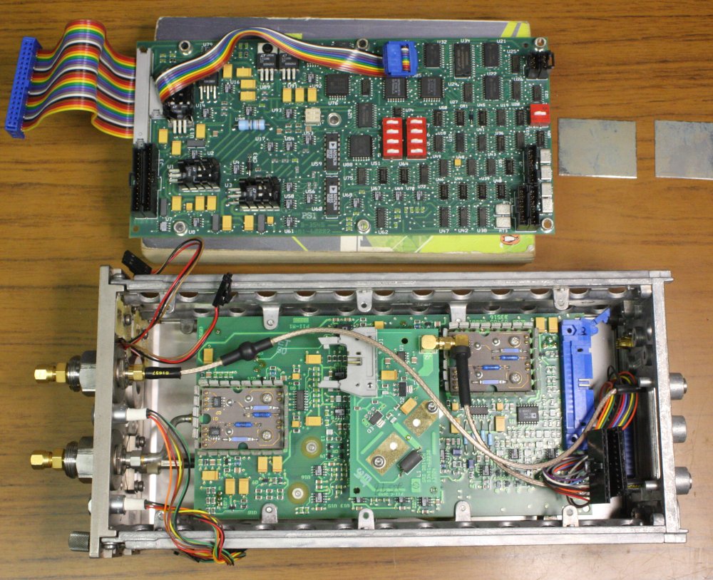
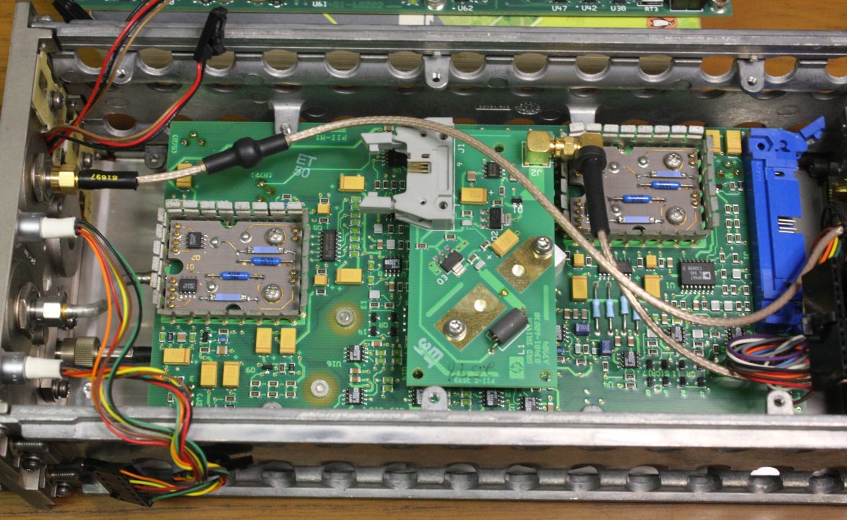
Also here's the insides of one. The other module is identical.
Fortunately he only screwed in the SMA connectors to loose finger-tight. Visually the APC 3.5 surfaces look OK still. Fingers crossed. I'll be trying them out as soon as possible, but that requires careful setup, and I have some other things to do first plus need to clear bench space to set up the HP 83480A scope. Do these plugins work? Oh, the suspense...
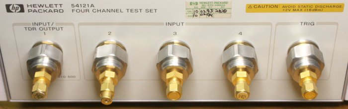
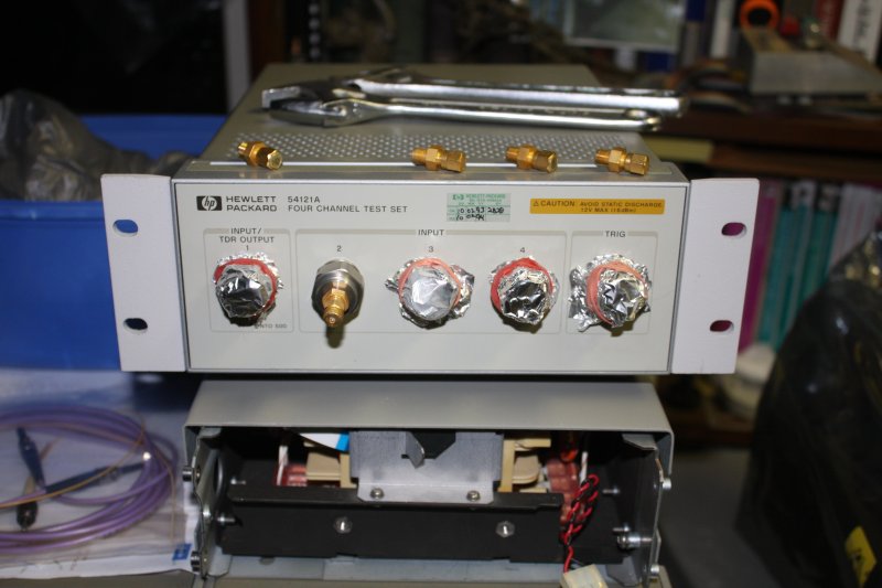
For now I can swap some APC 3.5 mm port protectors over to these from my HP 54121A sampling head. Until I find an affordable set of four. The ebay search term is HP 5061-5311 — you can find out the new cost! I do have plenty of 50 ohm SMA terminating plugs.
 |
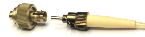
One thing I'm ecstatic about, is that while most ebay modules like these also have the optical port adapter removed, both of mine still have it. Adapters (above) are made for various different kinds of fiber optic connectors. There are many. Best of all the ones on my modules are for a common connector type (above) called ST, that I have plenty of in my collection of assorted fiber optics. Also widely available. The module's optical ports use 9/125 fiber, which is Singlemode.
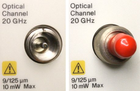 The bare optical port without any adapter looks like this: →
With an adapter and dust cover (after I found some), like this: → →
Modules that were cared for and expected to actually work would have an adapter and dust cover. Yet most of these modules on ebay have bare optical ports, and people still pay such prices?
Is that bare port a standard, or something proprietary to HP/Agilent? Would new adapters be available anywhere?
I had no idea; just glad I don't have to deal with it. But it turns out it would only have been a 'further expenses' problem.
← Here's a list from the 1999 HP manual for these modules, listing accessory options. The optical port adapters highlighted. Search ebay; all are available (for often absurdly high prices.)
Where did all the adapters go, off plugins listed for sale missing them? These photos are a hint. Ebay sellers with dozens, presumably removed from equipment that's useless without them. Prices are from the ebay listings, US dollars, per unit incl postage to CA, USA. Really!
These sellers with stupidly high prices also have the most in stock. C&E.
How ironic, that at the same time I'm restoring an old valve-based 25MHz oscilloscope, I'll finally commission a scope with 20GHz electrical and optical bandwidth. Let's hope it doesn't take six years to get the Tek 561B going. Though at this rate...
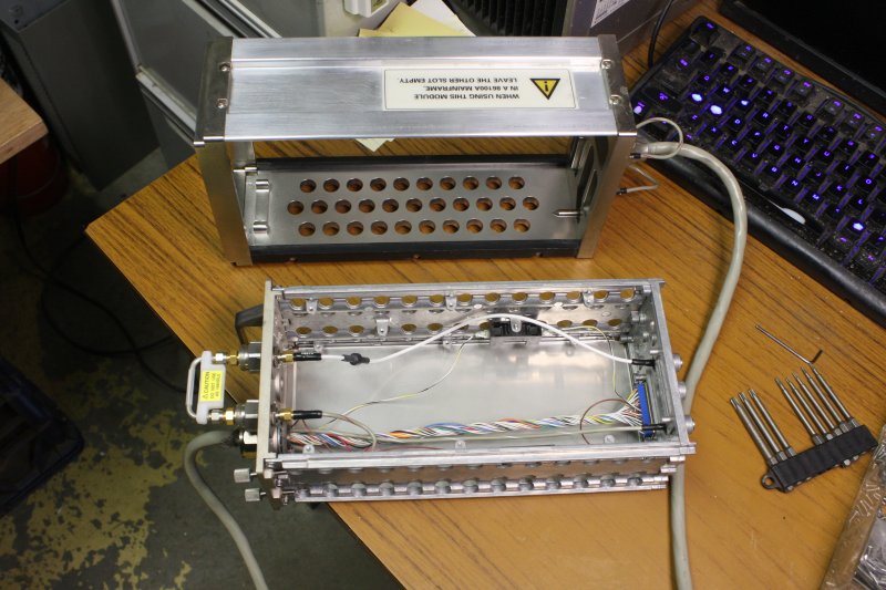
That evening after the plugins arrived, there was one quick thing I could do in preparation. If they have any problems, I'll need that extender unit which arrived a few days ago. But first it needs some simple mechanical repairs.
 |
 |
 |
 |
 |
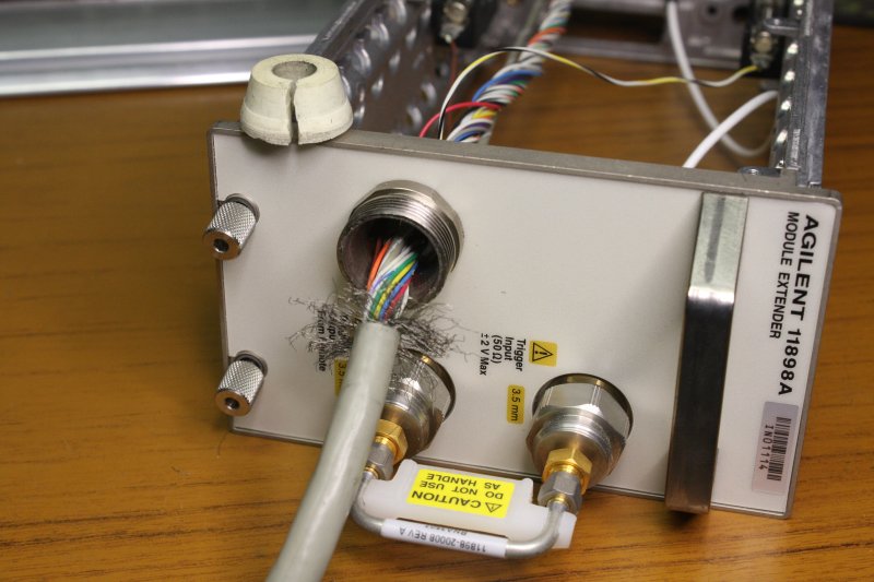
1. Of course the old stick-on rubber feet were mostly missing, and of course Bunnings didn't have the square black ones. So, replacing with round ones. They'll do. And can stay even though I did later get square black ones at Jaycar.
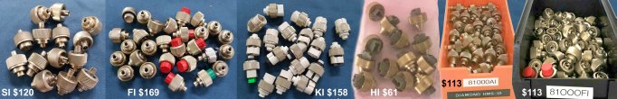
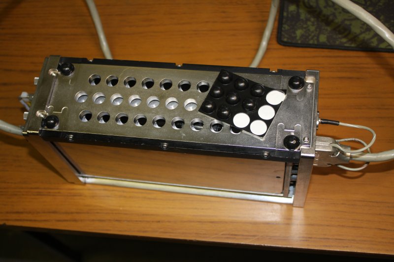
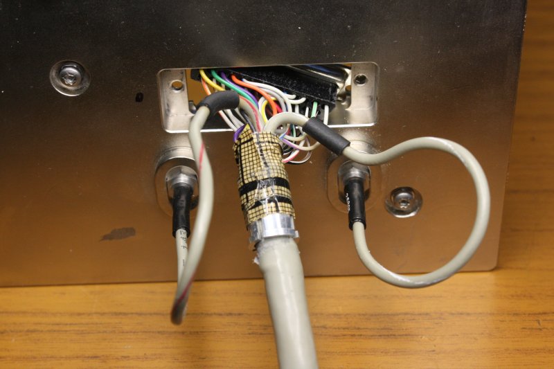
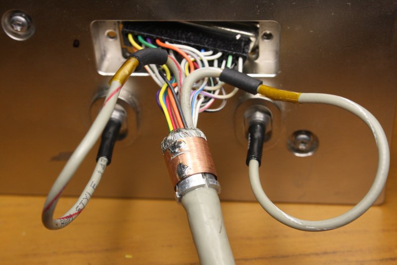
2. The D25 signal connector inside the module receptacle frame. Forgot to take a pic of the outer shroud, but the cable is very loose in it.
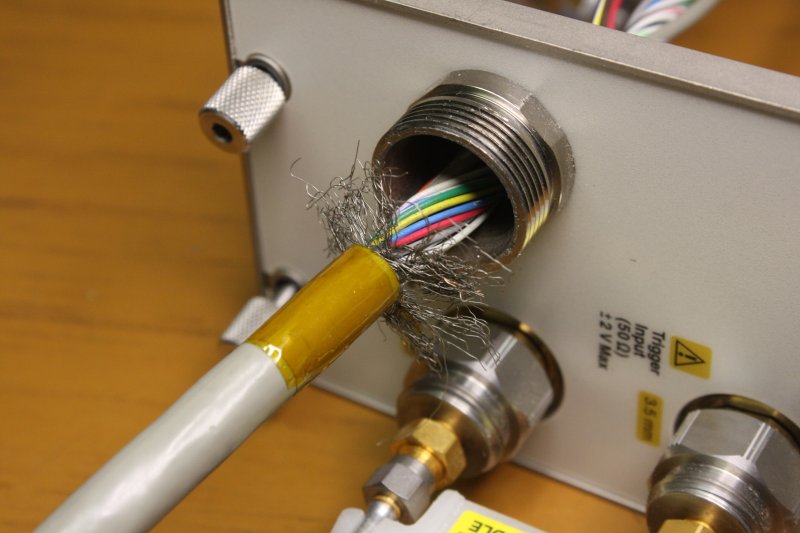
3. Opened, and whut...? The shroud doesn't really clamp the cable, and that brown stuff is... some kind of antistatic tape? Being used to 'secure' the cable braid? But... the conductive pattern is only on the outside of the tape. Not touching the braid, but the braid is touching the aluminium ferrule, and that touches the the metal shroud, which is screwed to the chassis. So the tape is just to keep the braid neat. Then why use 'anti-static' tape?
4. Tape removed. Yep, braid touches the ferrule, but poorly. Intermittent shielding ground? Great.
But the main problem is the ferrule doesn't clamp the cable sheath, which is loose and able to slide in and out.
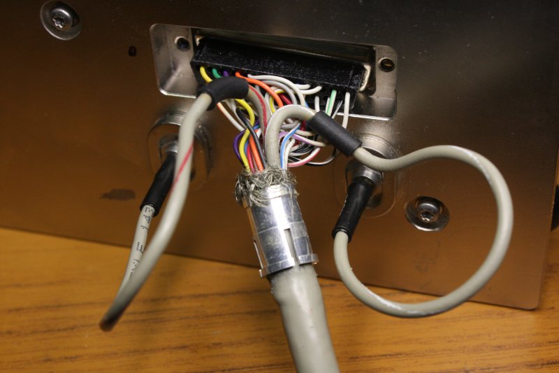
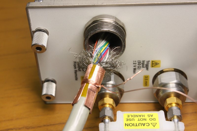
5. Cut back the sheath a little to free more braid. Braid folded back over the ferrule, then held by a copper foil sleeve. Temporarily held tight with some copper wire. The braid and sleeve will take up the free room in the shroud, letting it clamp things properly.
 |
 |
 |
 |
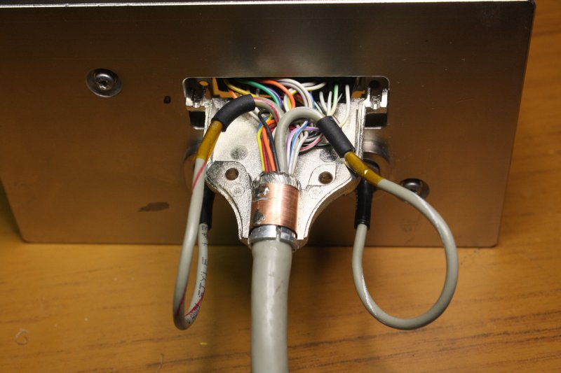
1. Soldered the sleeve.
2. Temporary wire removed. It would not fit inside the shroud. Some kapton tape around the two coax where they pass through holes drilled in the shroud. For abrasion protection only, the cables are not clamped tightly. (Can't clamp coax, squishing it creates an impedance dicontinuity.)
Also, it's barely visible, but here I've super-glued the main cable sheath into the aluminium ferrule. No more sliding!
3. Checking fit.
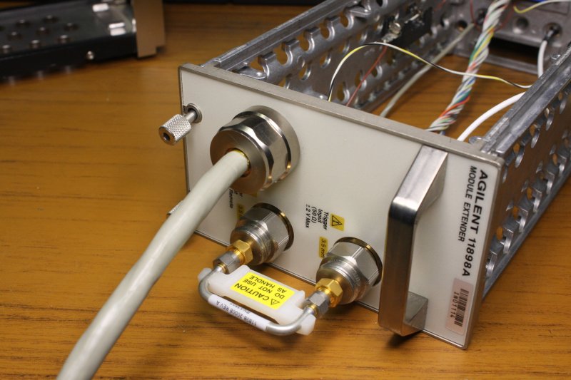
4. Assembled. A good firm structure now, with a solid ground connection from braid to frame.
 |
 |
 |
 |
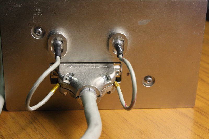
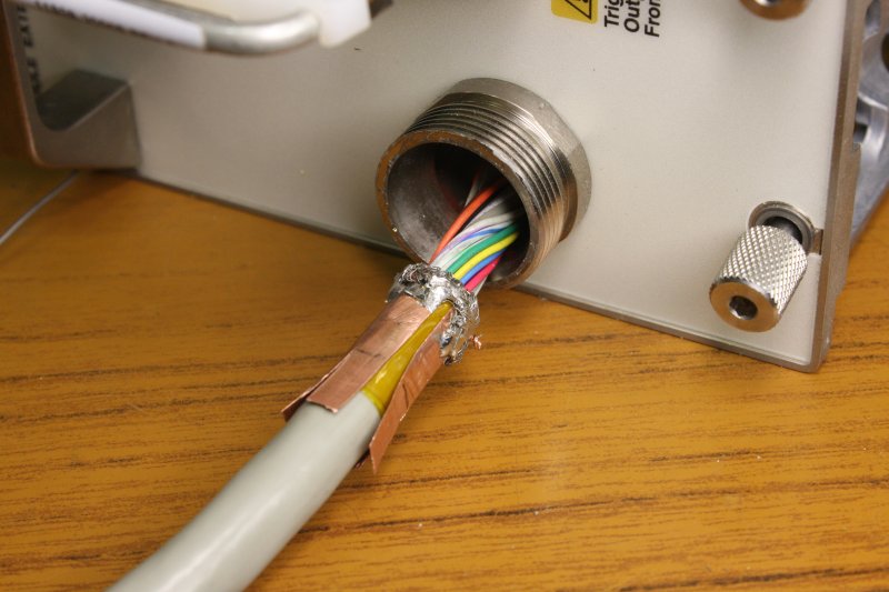
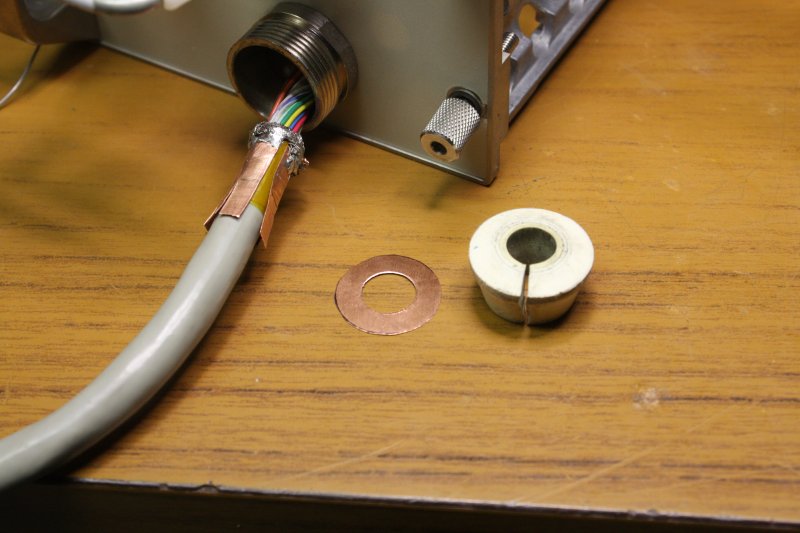
1. The cable other end was worse. It came like this. Braid completely disconnected, cable unclamped.
2. Teasing out the tangled braid, and slit the rubber clamping cone.
3. I'll be soldering braid here, so added some capton tape to protect the sheath.
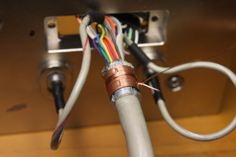
4. A copper ferrule, not overlapped because space will be tight. Also to let the rubber cone grab the cable. The outside end of the copper is cut in 'petals.' Binding wire is temporary.
 |
 |
 |
 |
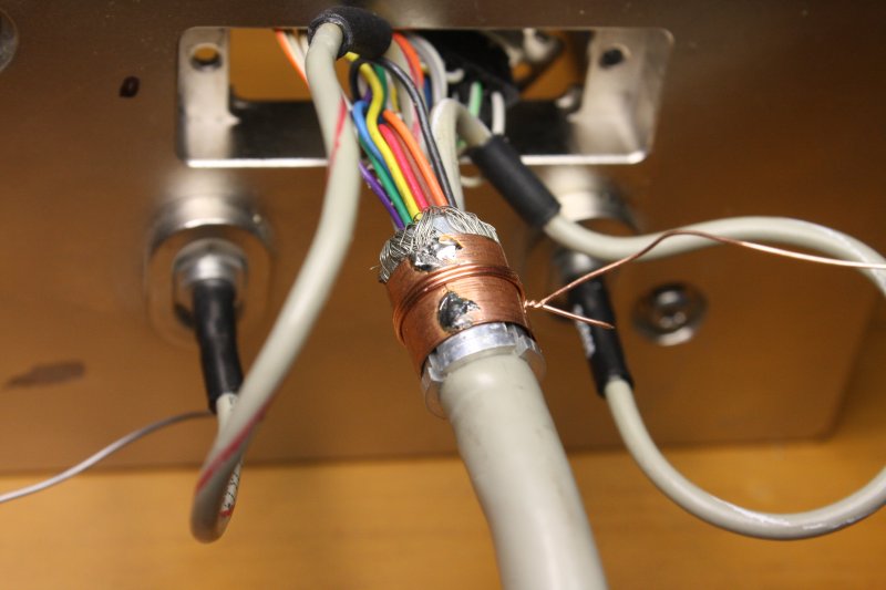
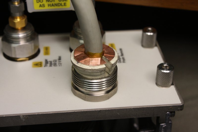
1. Braid folded back over the copper, a couple of turns of copper wire at the end, then the braid folded back over that wire, then soldered. Quickly and in short bursts, to not melt cable insulation.This thicker part will be past the inner end of the rubber cone, so its thickness doesn't matter.
2. A copper foil washer cut.
3. The rubber cone in place, foil washer added (slit to get it onto the cable), then the ferrule petals folded down over it.
4. The gland nut screwed down. Now this end of the cable is good too.
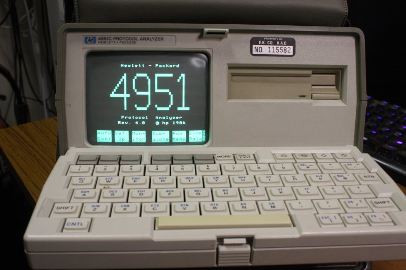
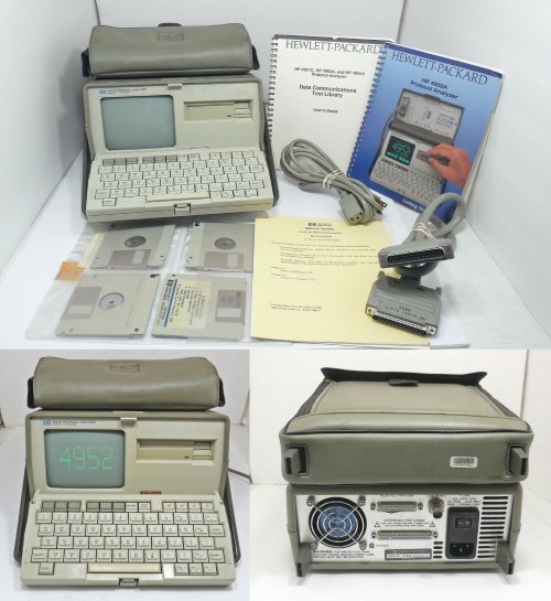 The next few days were busy with chores (eg car registration) and some more parcel arrivals. The first was a HP 4952A Serial Protocol Analyzer, on the 28th.
The 4952A was introduced in 1986, when I was 30. Subsequently for the rest of my professional career I wished I had one. But back then they were too expensive for me, and more recently it wasn't so much the instrument cost but the shipping, plus there was always something more urgent.
← Here's one of the ebay seller's photos. For old things like this there are always pros and cons. This one is missing an interface pod (required!), has the interface cable, an original floppy and two manuals (but neither is the full user guide.) Listed for US $76.50
Pods and manuals are available, but any original manual is going to cost $15+ so there's $30 (ie item is $46), and original disks are even rarer. There are several kinds of pods; would have been good to buy a unit with a pod, but I don't mind buying that separately.
Another plus is the seller is in CA. Short shipping distance to my reshipper in LosAngeles. This is as much an issue of damage probability as cost.
I'd bought it, then set about locating necessary extras (manuals and pod) while this went through shipping from seller to me in Oz. I'd downloaded several manuals in PDF and the Data communications Test Library, and bought an original Operating Manual.
Discovered that disconcertingly there seems to be no known service manual for this model, though there is one for the similar model 4951C. Just one online mention several years ago of a 4952A service manual existing, with no way to follow that up. Again I curse the closure of all the great old manuals repositories.
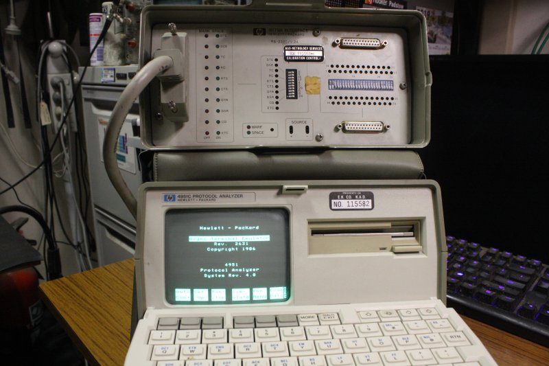
Somewhat amusingly, looking for an interface pod, I found the best way to get the one I wanted was to buy an entire 4951C that included it, for US $35. So that was on its way here too.
 |
 |
 |
 |
 |
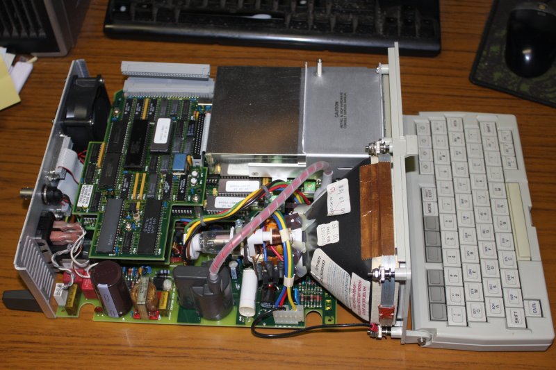
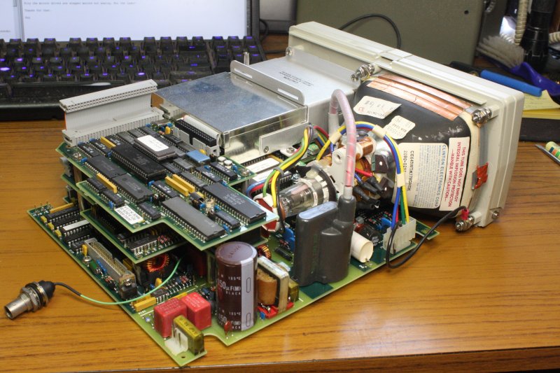
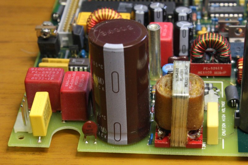
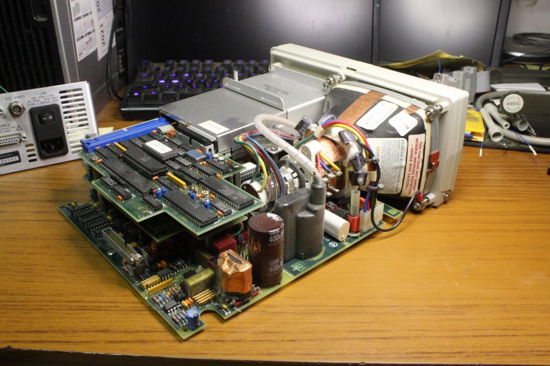
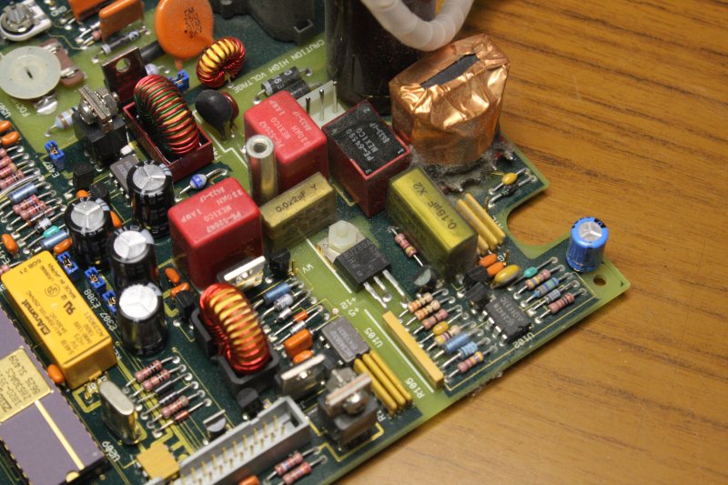
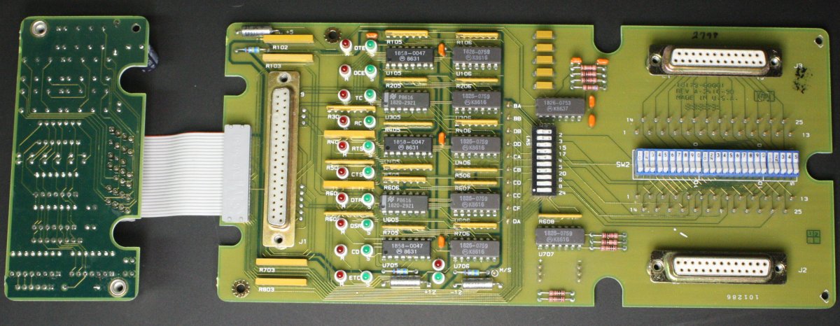
1. It arrived fine, except missing the case. No, I kid, it runs and that's just me opening it up to check things.
2. Such as, does it contain the dreaded RIFA caps? Yes it does! The two yellow coloured things near the front edge of the board. Pretty much guaranteed that if the machine was powered up for long, these old things would burst into smoke and flame. They have to be replaced with modern 'non-smoking' caps.
3. Another view. It's quite a packed little thing.
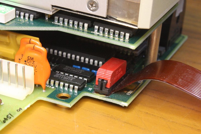
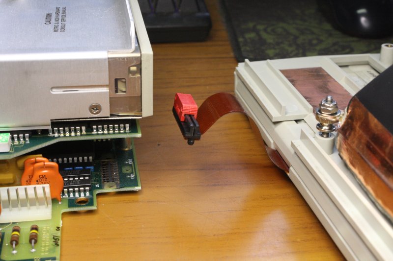
4, 5. Interesting connector on the flexible PCB cable to the keyboard. Slide to release. I'd never seen these before.
 |
 |
 |
 |
 |
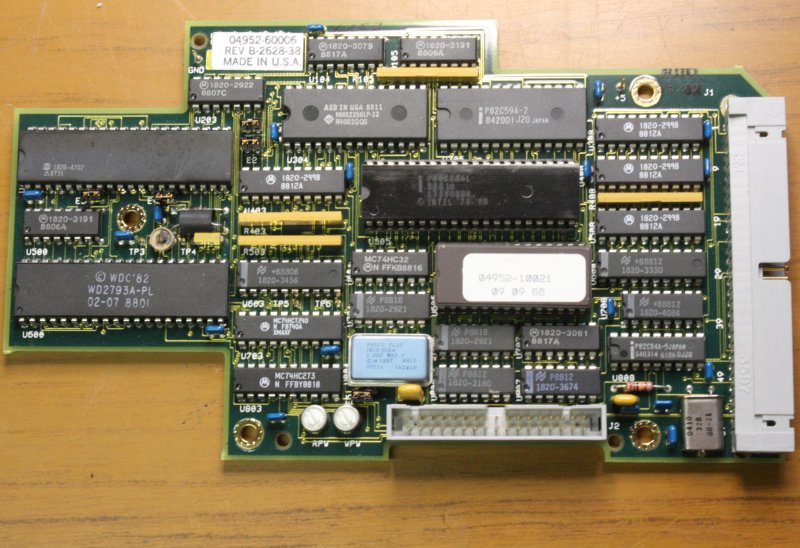
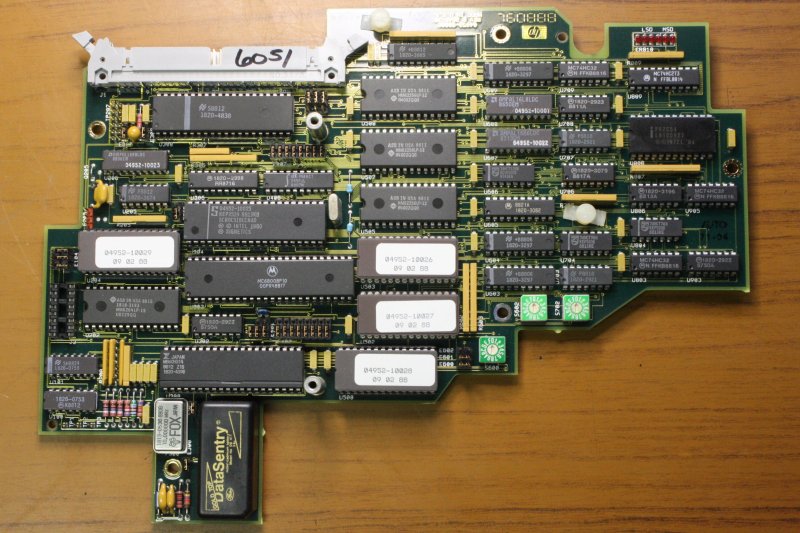
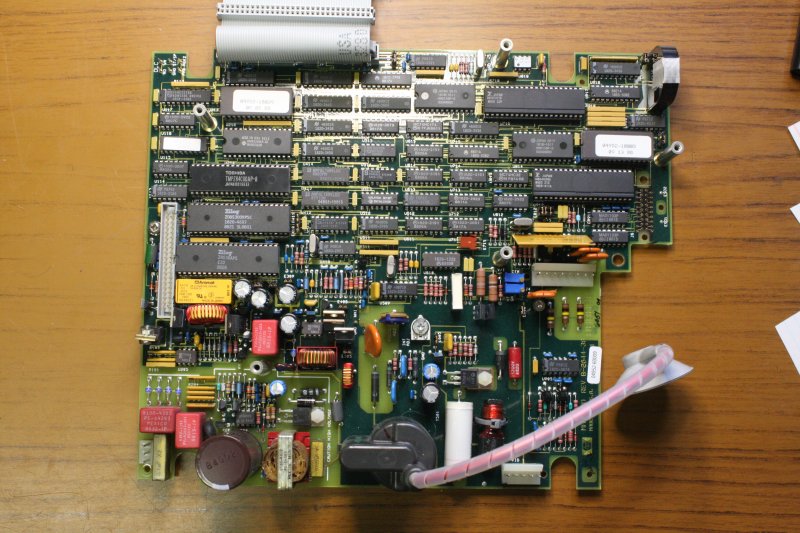
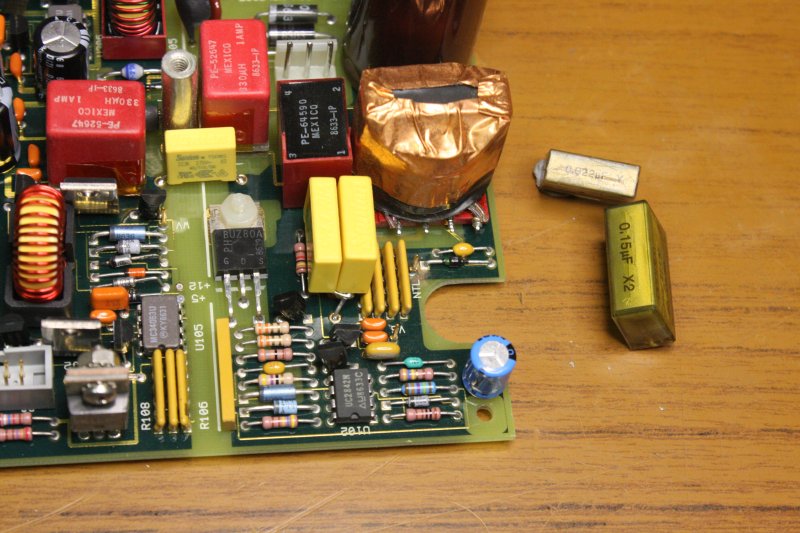
1 - 3. Top, middle and bottom boards.
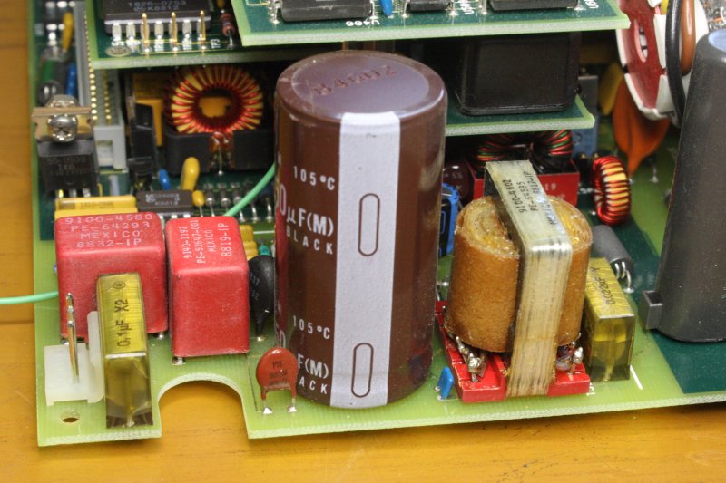
4. The RIFA caps replaced. These components have mains AC voltage across them. RIFA caps are cast in an epoxy, that shrinks and cracks with age. Moisture infiltrates via the cracks and contaminates the insulating film. Which then fails and begins arcing. The arc progresses through the capacitor body, converting much of it to stinky, sticky smoke. It's something to avoid.
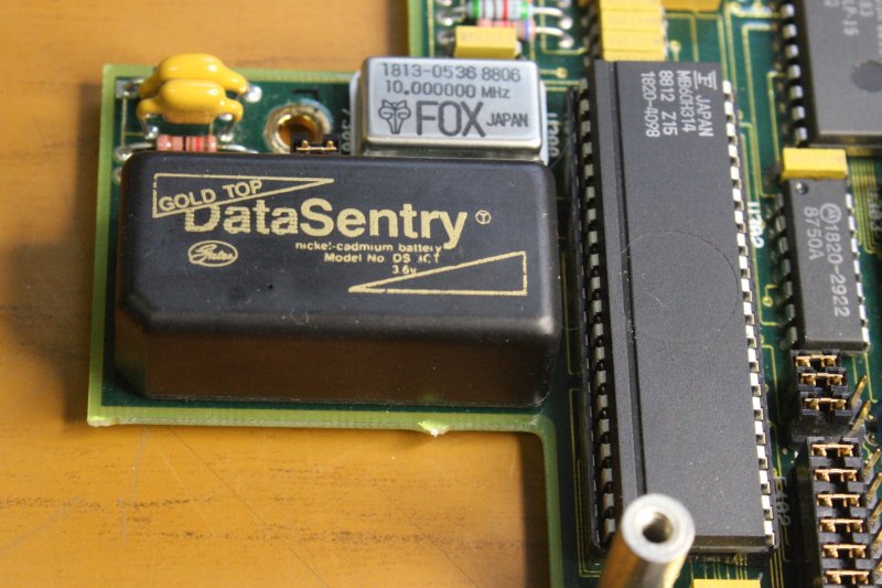
5. Another thing to generally remove from old electronics, is the Nickel Cadmium batteries often used for CMOS RAM data backup. When aged, typical NiCd batteries leak a corrosive fluid that utterly destroys all components in an ever-expanding circle of creeping chemical doom. Hmm... this is a NiCd. But amazingly it still holds a charge, and seems to be some 'better packaged' version. I'll see how it goes.
 |
 |
 |
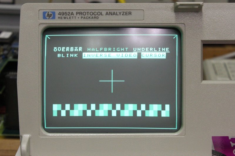 |
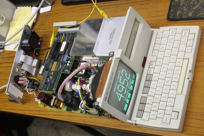
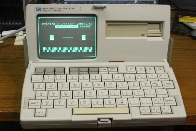
1. Back together (mostly) and still works. Always a pleasant moment.
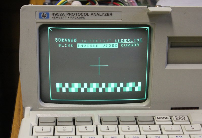
2. A small problem obvious at first power up on arrival, is the screen image is offset to the right, and not full width. Irritating because the menu keys don't line up with their screen labels. Have to fix it. There's also a bit of distortion from rectilinear.
3, 4. Some fiddling with yoke magnets and video adjustments later, it seems to work better with most of the linearity magnets removed, shifted neck ring magnets, and some width increase (via the slug in the coil mounted on the yoke.) I rotated the yoke to fix that slight tilt, after these photos. The CRT EHT voltage is 9.1 KV, but without a service manual I don't know if that is correct. It seems in the right sort of range.
While it was apart I copied all the EPROM contents: HP_4952A_protocol_an.zip 125 KB.
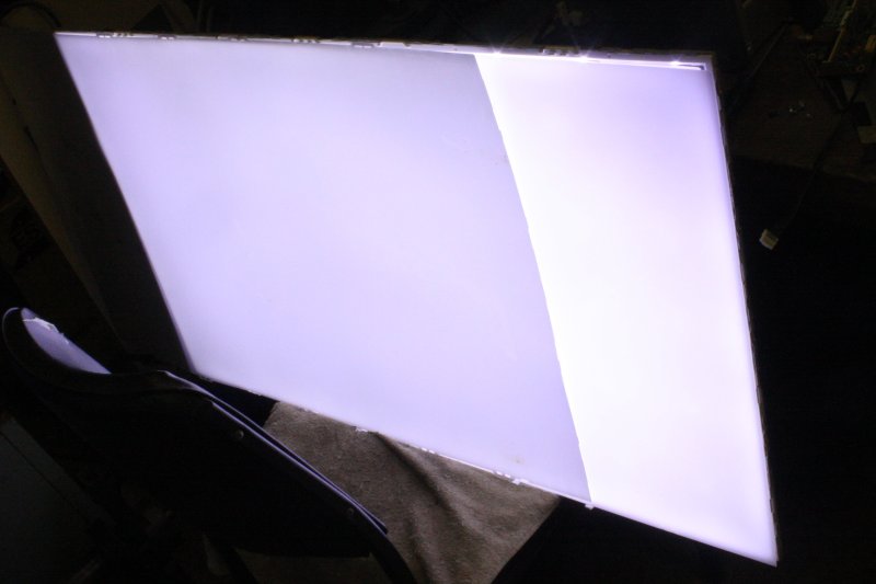
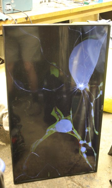 People should be more careful of their large flat-screen TVs.
Or not, since when they break them and throw them out, I get some entertainment. This one at left powers up and some light gets through the smashed LCD in interesting patterns. Point being that the backlight is working... and it is an LED backlight type. Good.
 |
 |
 |
 |
 |
 |
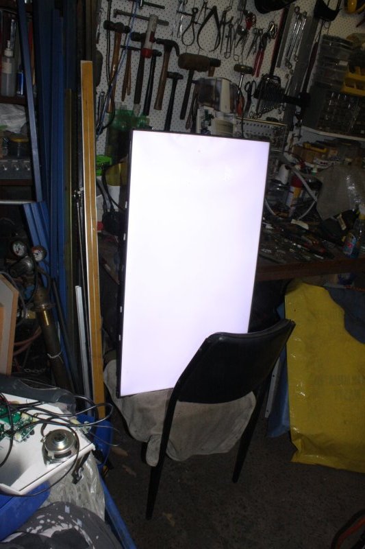
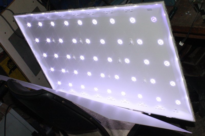
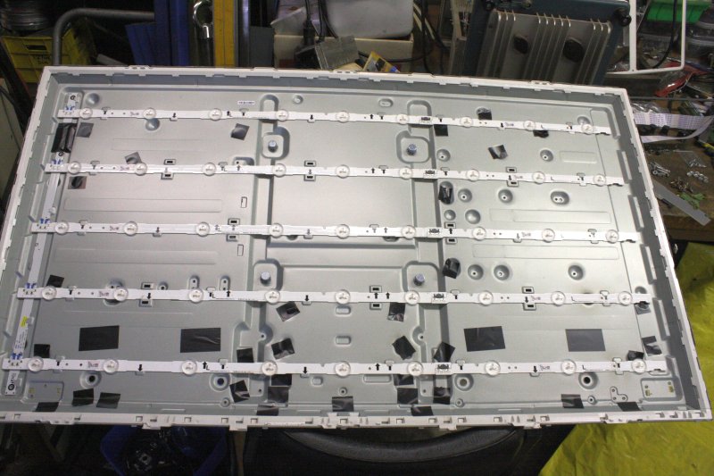
Quite bright after discarding the broken LCD pane. The camera doesn't do it justice. Also the camera thinks it's purple tinted, but actually it's a nice clean white.
Best of all, the power supply board turns the backlight on full at power-up, even with the TV CPU board disconnected. This is what I was hoping to find, for a light table build. Something that will just turn on and work.
That was a morning time-filler, since I knew these boxes would arrive today...
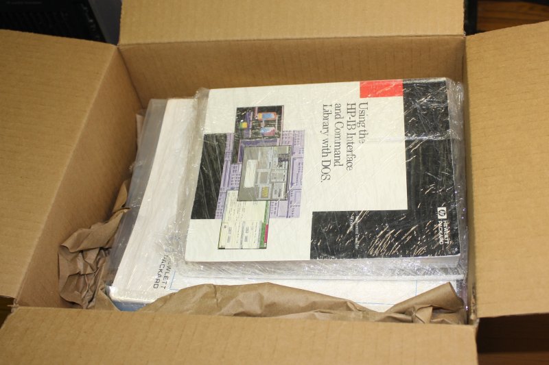
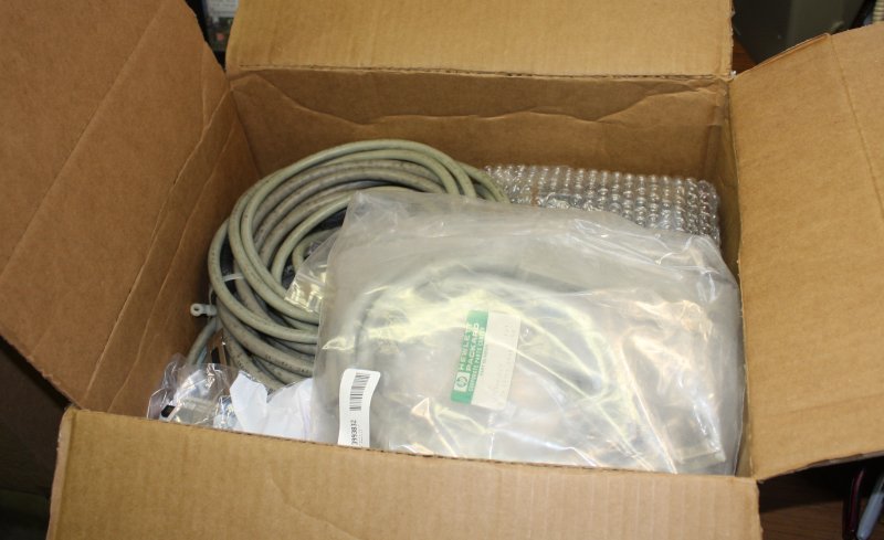
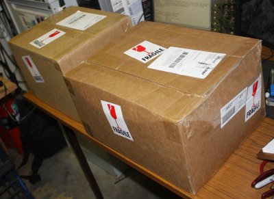 Something of a pile of stuff had built up at my US reshipper, awaiting consolidation. Recently I'd had it all packed into two boxes — one containing all the books and manuals, the other all the hardware. Cables, circuit boards, and gadgets.
They arrived in the early afternoon.
 |
 |
It all went well, except for one small shipping damage.
 |
 |
 |
 |
 |
 |
 |
 |
 |
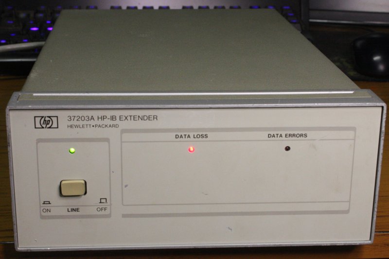 |
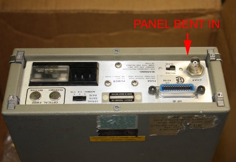
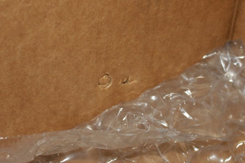
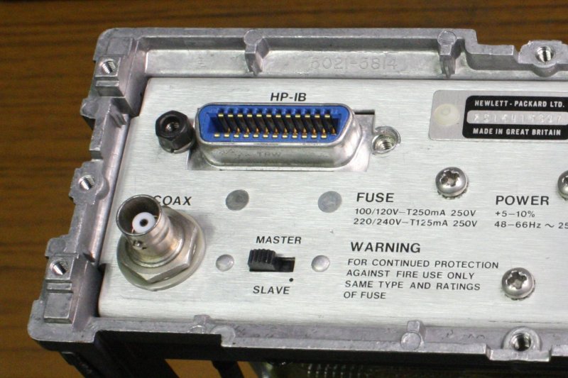
One of the items in the hardware box was a HP 37203A HP-IB Extender. (Discussion thread here.) This was a curiosity buy — it only cost US $16 + $9 domestic postage, and since it's light and would be consolidated with other, heavier things the incremental postage cost from USA to Australia would be small. I didn't research it at all before buying, just wanted to know how a 'HP-IB extender' worked. More like a surprise present for myself. I thought it would be something like two HP-IB connectors on the back, with some kind of signal level boosting circuitry. I've been working towards using HP-IB (Hewlett Packard Instrumentation Bus) to interconnect and run some HP-IB gear I have, so anything HP-IB related is of interest.
Unfortunately the packer at my reshipper put it in the box with a rear BNC connector hard up against the box. The box got bonked, and the connector end cut a neat round plug out of the cardboard [pic 2]. Didn't bend the connector, but did push in the aluminium sheet rear panel on which it's mounted. [pic 1]
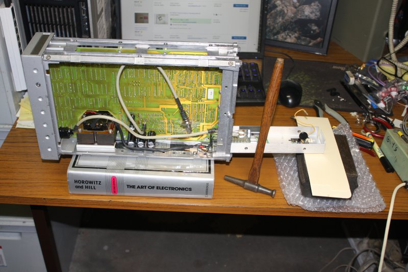
Quite minor damage, and an easy mechanical fix. In this case I applied The Art of Electronics and a hammer [pic 3]. The book happened to be at hand when I needed a spacer to rest the instrument on. Couldn't remove the back panel entirely without unsoldering some mains wires, and this was easier.
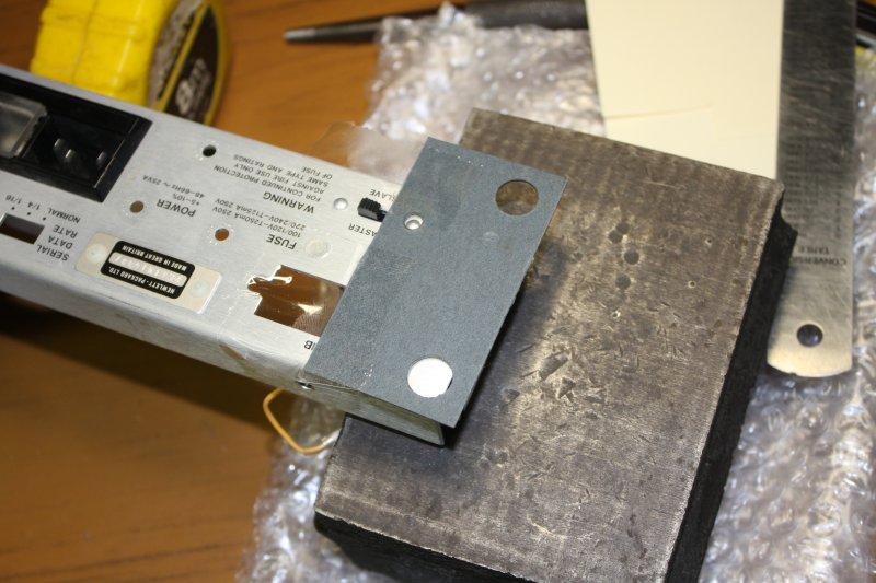
4. The bent area extended past a rivet that stands out from the rear surface. So I cut a shim from a random sheet of tough insulating material. It also protects the aluminium surface texture while hammering on the steel anvil block. Taped on, so it doesn't move around.
5. After the panel was flat again, while reassembling everything one of the HP-IB connector mounting screws sheared off with very little force. Clearly it had been near failure since original manufacture. It's an interesting failure mode. A sort of conical shear, suggesting the screw was originally produced in two parts (saving some material waste and machining effort) then friction welded together. But on this one the friction weld was poor.
2nd Row:
1. The two parts just 'click' back together, but of course fall apart if touched. If I can't find a new replacement I can possibly silver solder this together, then re-black the metal.
2, 3. The interior. My guess about how this works was wrong. Actually it encodes the HP-IB state in data frames, transmitting at high speed serially over a single coaxial cable, in half-duplex operation. Hence one needs two of these units. Would be quite interesting to see it working, look at the data frames with a scope, etc. So, next time I see another one going very cheaply I'll buy it. Already have an op/service manual on the way here.
4. The back panel, fixed. You can't tell it was ever bent. (And there's where that broken screw should be.)
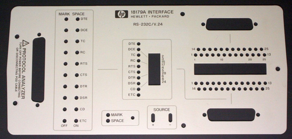
5. A very boring front panel. It either works, or doesn't. Without a mate, it doesn't.
 It's been some time since I mentioned the Tek 561B scope, hasn't it?
It's very typical around here for a stream of time demands to stall progress on some supposedly 'top priority' project. This is what's happening at the moment. And it's going to go on for a while yet. However the 561 is still occupying my mech-workshop bench, so isn't forgotten. I'm doing minor things on it in spare moments, like preparing a few small parts for spray painting along with that top rail. It's been raining a lot lately, high humidity, so spray painting atm isn't advisable even if I had a chunk of time.
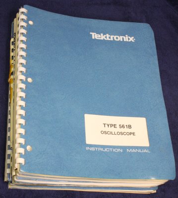
← Meanwhile among the manuals in a box today, are all the original old Tek 561-series oscilloscope manuals I'd bought recently. This makes a huge difference to viability of the whole project. Yes, I'd found and downloaded PDFs of most of these, but they are ghastly. I dislike even looking at the awful quality found in most so called 'scans' of old manuals. So many visual flaws, so many reminders of how much is lost by inadequate techniques combined with shortcomings intrinsic to the PDF format. But that's a story for another time.
The contents of these manuals are a joy and a beauty to behold. Relics from a bygone age, when draftsmen were real artists, and hand-drawn illustrations combined with photograpic print production process achieved results very different from today. Eventually I'll get digital representations onine that do justice to the content, but that's part of another large project and will take a while (years...)
With these ones the old plastic comb binders are brittle with age and some are broken. Doesn't matter, I have a comb binding machine and boxes of new combs. Easily replaced.
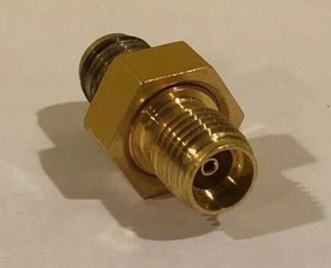
Those old Tek manuals are gold, and today I also bought five of the golden APC 3.5mm connectors, for $200. They are used, but $40 each is a good price relative to ebay average. The one illustrated looks correctly used — one end left in the port all the time, the other (rear in pic) suffering wear. Using stainless steel SMAs makes the surface dark like that. Not a problem.
They'll take a while to get here. HP / Agilent PN: 5061-5311
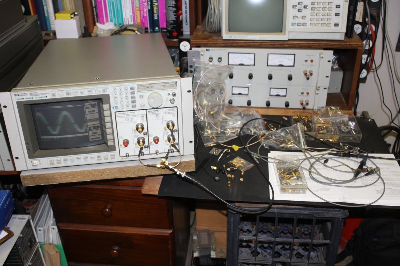
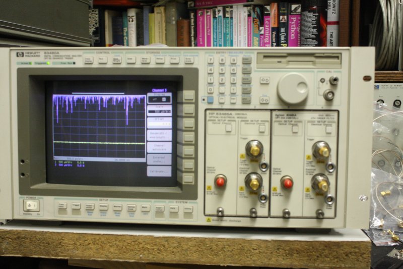
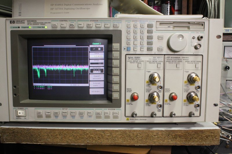
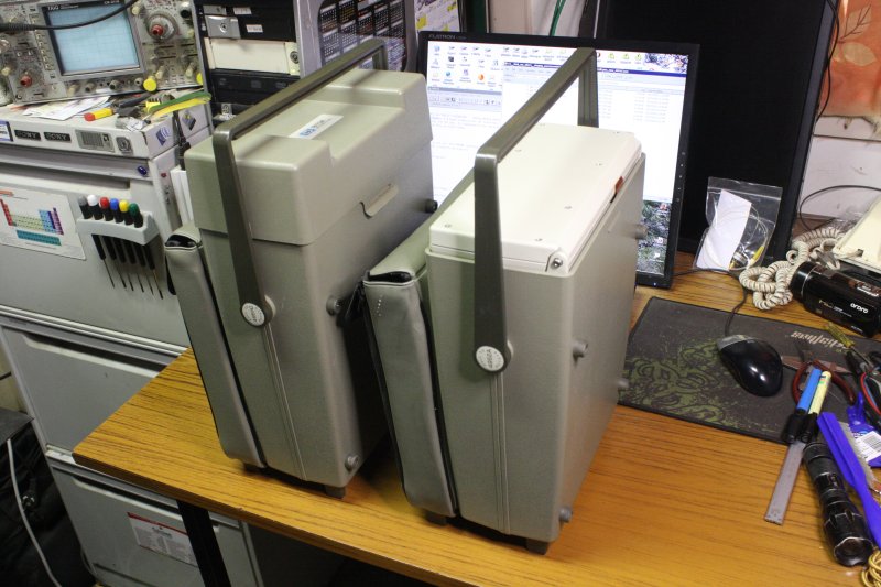
The two HP 83485A plugins had arrived on Feb 25th. I'd been dying to try them, but only today 9 days later managed to get time and space clear to set up the HP 83480A mainframe scope. It was in my storage shelving, large and very heavy too. Slightly strained my back moving it, but never mind.
 |
 |
 |
 |
 |
 |
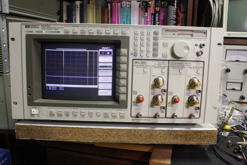
1, 2. Setup, and at least it still runs after a long time sitting on a shelf. The waveforms on screen in pic 1 are from memory; were there when I bought it. I cleared the waveform memory now.
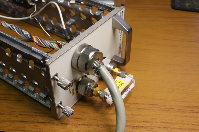
3-5. Taking the APC 3.5mm f-f protectors off my HP 54121A, putting them on the two 53485A modules.
6. Resulting configuration. Now, are these modules going to work? There's well over a Au$1000 riding on this, so I'm really feeling the tension at this point.
 |
 |
 |
 |
 |
 |
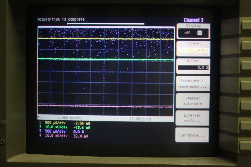
On powering up, no smoke and the mainframe recognizes both modules. All four 'Setup channel' buttons work. A good start.
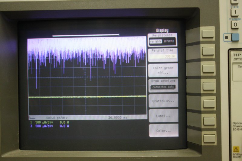
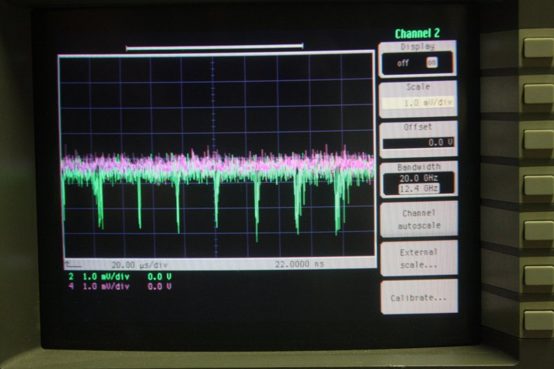
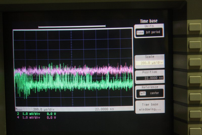
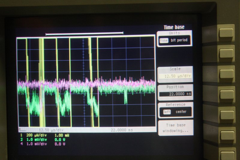
1. First check, turning on all 4 channels (2 optical, 2 electrical) and seeing if the traces appear and can be adjusted on screen, with no signal inputs. In this pic there should be 4 traces, each 2 divisions apart. Sigh. First fault!
Trace 3, the optical channel on the Agilent branded module, can't be adjusted. It's producing random value samples, mostly off the top of the screen and doesn't respond to the vertical offset control. Damn.
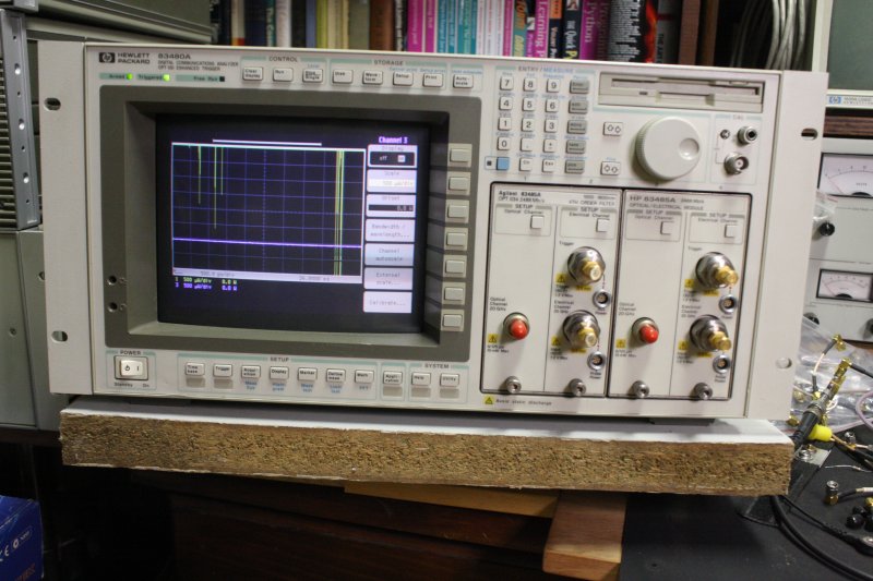
2. Both optical channels turned off, and the same signal applied to both electrical inputs (2 and 4.)
About 500MHz sine, via a 3dB attenuator, a propper splitter, one side going to a trigger input, the other to a T, then both channel inputs. (I only have one propper SMA splitter.)
Hmm. All in coax, and I'd have expected the signal to be a lot less noisy than that. Maybe I'm wrong, will need to look up the specs. But in general both channels are working and very similar in results. Both module trigger inputs tried, both working. (Not surprising considering they are really just a co-ax pass-through connection to the mainframe.)
3. Setup. The siggen is off to the right.
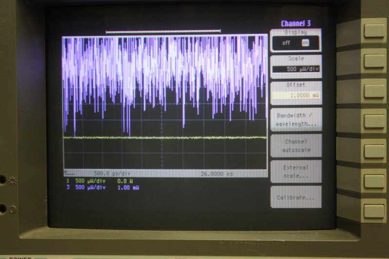
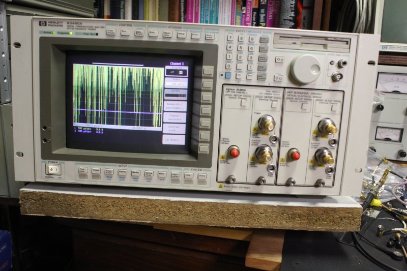
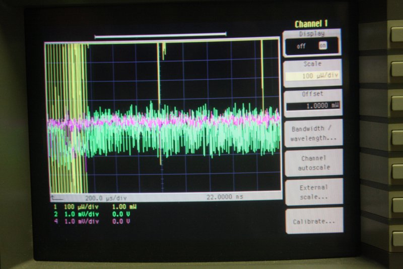
4-6. Trying to get a handle on what the Agilent module optical input is doing. It's very noisy, and drifts up and down. Sometime partially on-screen, sometimes almost entirely off-screen to the top, unadjustable. This is all with that module in the right-hand slot.
I'd also tried shining both visible and IR lights of various kinds (bright LED torch, greem laser, appliance IR remote LED output) into the optical port of the HP module. Even with the optical port sensitivity set to maximum, none of these produced any deviation of the flat trace at all. So it's looking like this module's optical port is dead too. I'd finally noticed that the data specs for the module say the port's input response (wavelength range) is 1200-1800nm, which is entirely in the near-infrared. This surprised me — I'd expected there to be some sensitivity into the visible light spectrum, even if it wasn't calibrated. Why isn't there? Is there an optical bandpass filter (IR only) in the light path?
 |
 |
 |
 |
 |
 |
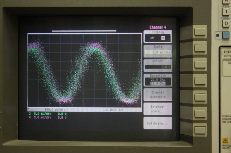
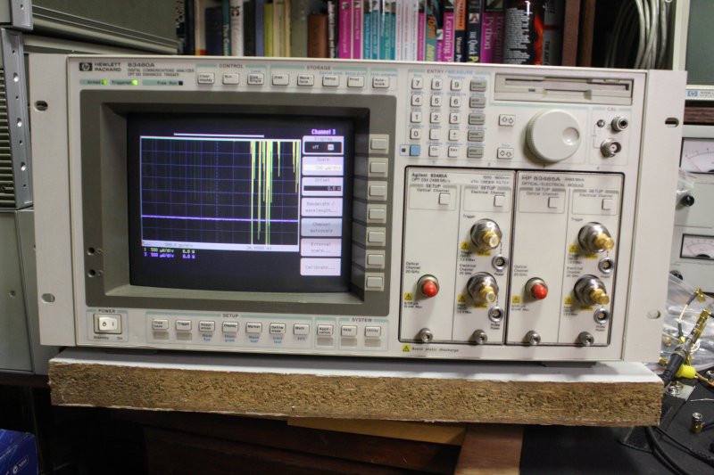
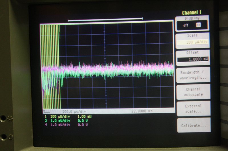
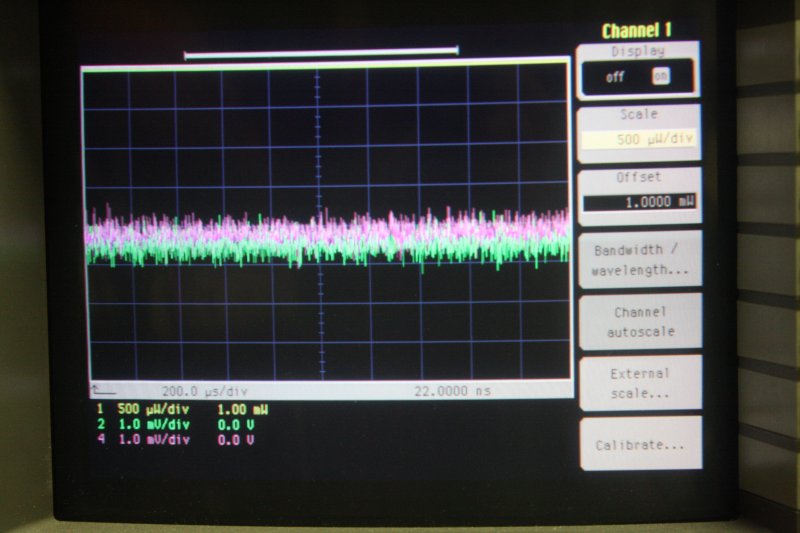
1. Agilent module still in the RH slot, its optical channel (3) onscreen is purple.
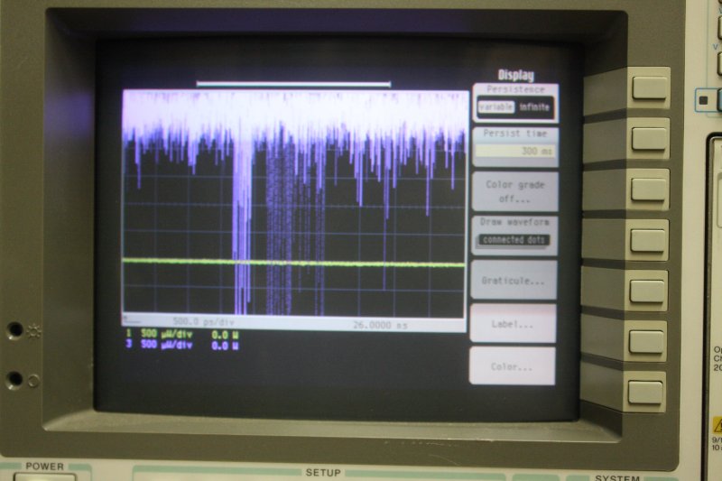
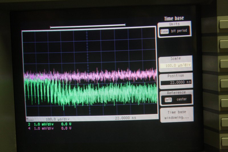
2-6. The Agilent module swapped to the LH slot, so its optical channel is now trace 1, yellow. Various sweep speeds, and at first it was mostly off the top of the screen. Anyway, the dead optical channel moved with the module, so isn't anything to do with the mainframe. But I'm starting to find there's some weird interaction between the timebase setting, and the behavior of the 'random noise.'
What sucks is that I've been hunting a service manual for 83485A modules for some time, and have had no luck whatsoever. It's starting to look like there isn't anything available. That's not good.
There is a 'service' manual for the 54750A scope (same hardware as the 83480A communications scope) and it includes a section on the 54751A/83483A plugin module, which has general similarity to the 83485A module. But there are no schematics (what HP calls 'CLIP' for component level information pack) so they are more or less a joke. The 'marketing-dept-mindset rot' had really set in badly at HP by the time these instruments were produced.
 |
 |
 |
Perhaps the noise originates in the optical sensor? With just the side cover off the Agilent module I tried removing the hardline between the optical sensor and the coaxial switch. (Which required modifying a small spanner to fit, see above.) Put a 50 ohm terminator on both end connectors. In this config the optical channel shows no trace at all. Off screen, but not noisy. Inconclusive. Replacing the hardline the module went back to the original behavior.
On the 'wiggle all connectors' principle I disassembled the Agilent module per the pics above, took the photos, put it back together. The behavior is unchanged from previously.
 |
 |
 |
 |
 |
 |
 |
 |
%%% include notes on the sweep and optical channel gain settings interactions with instability/noise in both the optical and electrical inputs with this module. Hard to identify cause without a schematic. All traces above are with zero inputs. Something about 'starting a sweep', makes the inputs unstable. Not sure what this implies in a digital sampling scope.
This is disappointing. Both optical inputs aparently dead, with that and other problems not going to be easily fixable without schematics and a service manual specific to these modules. Which doesn't seem to be available. Sigh.
 |
 |
 |
 |
 |
 |
 |
 |
 |
 |
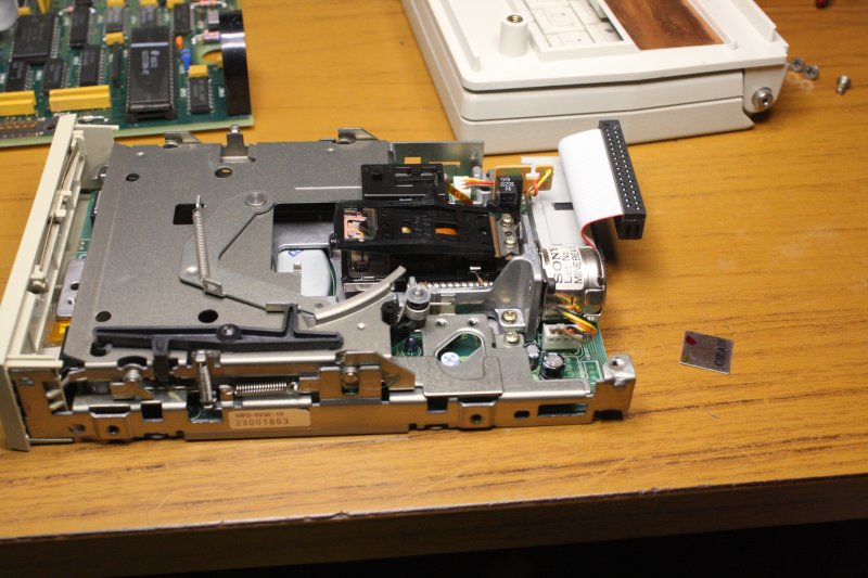
Deja vu. Open it up, replace RIFA caps, minor fixes like reglue a metal shield onto the floppy head, check the NiCd battery (flat but does take a charge, we'll see how it goes), adjust the image position on screen, dump the EPROM contents, reassemble.
Between the two models the floppy controller boards appear to be identical though they have different part numbers. Everything else (bottom and middle boards) are very different. Here are the EPROM contents: HP_4951C_protocol_an.zip
81000AI Diamond HMS-10/HP      Bought 1  $19.95
81000FI FC/PC/SPC/APC
81000HI E-2000
81000KI SC
81000NI FC/APC Narrow Key Way
81000SI DIN 47256/4108.6       Bought 2 $45/pair †
81000VI ST                     Have 2, with plugins.
81000WI Biconic                Bought 1 (nib) $39.99
On the assumption (shaky) that I'll be able to fix the optical input ports on my HP 83485A plugins eventually, I thought I'd start slowly collecting samples of the adapters for different optical fibre connectors.
According to ebay there's a few more recent types than in that table earlier →
One motivation is the lack of a good pictorial guide online to the different fibre connector types. There are some, but mostly in annoying pay/account-only sites like Pinterest. Surprisingly the Wiki page is quite sparse, with no pictures at all of the mating panel-side connectors.
Mostly the prices for these little adapters are absurd, with plenty of hoarding and fanciful expectations evident. But on ebay there are often sellers who don't care about maintaining artificial prices, and just want to sell something. I'm in no rush, so I'll buy samples when I see listings at outlier low prices.
Unfortunately my very first try, on the 6th, encountered a different type of outlier.
 |
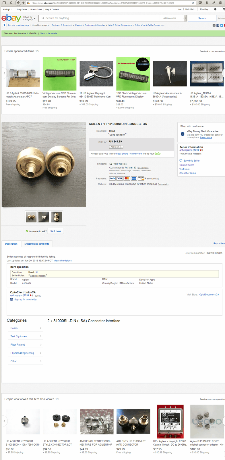 |
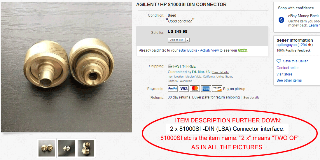
A listing for the 'SI' type, with title: "AGILENT / HP 81000SI DIN CONNECTOR" and price: US $49.99.
That's above my price interest range, but the picture showed two units, and the post details were "Free" and seller in California. Which meant quick delivery to my reshipper in Los Angeles. So I scrolled down.
The description reads "2 x 81000SI -DIN (LSA) Connector interface."
Screenshots of listing at right. Click thumbnails.
Nothing but that, and it's clear, it means the price is for the two in the photos. There's an ambiguity vs the singular title, but he can't possibly have typo'd "2-space-x-space" in front of the item description, so it must mean what it says. And Ebay description details override the titles, which are often abbreviated for space or 'eye appeal.' Cool, now the price is appealing. I bought them, and went on to other things.
On March 8th the parcel arrived at my reshipper. They sent photos. There's only one adapter. Sigh. I guessed someone packing the sale had only read the listing title, and made an honest mistake. I messaged the seller, asking about this. Here's the entire exchange.
Probably boring to read if you're not the one feeling cheated. But maybe you'll see what I mean by 'outlier.' There are not many like this on ebay, but you do come across them. This guy and the magnitude of money involved are far different to the Spectrum Analyzer saga back in Feb 2019. But similarly far from 'ebay normal.'
My general 'to do' lists are kept on sheets of A4 photocopy paper, on multiple old fashioned masonite-back clipboards, with the spring clip at the top. I write one-line entries as I think of them, and cross items off as I complete them. Overall the chores tend to accumulate faster than I can get them all done, so the 'general backlog' clipboard paper stack gets thicker over time. Now and then I review it all, consolidate and categorize, re-evaluate life choices (no not really), transfer some whole pages to the 'done' file in a cabinet. Which makes for a loose kind of diary, since every page is dated.
There's a category for "Buy : Major items : Tools." In that, percolating up around the top for over a year has been "Spot Welder."
It's not just a whim; there's a 'workshop infrastructure' project stalled until I get a spot welder. I want to put in some fume exhaust ducting (soldering bench, vacuum pumps) with an exterior vent in a wall. Which I'd rather do in sheet stainless steel so it never rusts. And mostly without using pop rivets or screws, so no projections into the ducts. Hence spot welding. Also I always wanted one, so yes it's a whim as well.
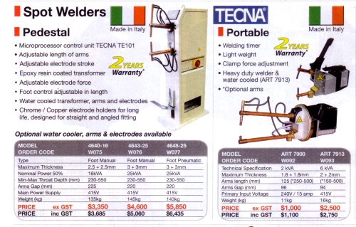 Here's a catalog from 2018, and a link for current prices.
New, they are not cheap. Especially since I want a pedestal type (foot pedal triggered, keeping both hands free to hold the work.)
Currently, most unusually I have some cash available. Plus a long list of things I need to buy, that is larger than the cash reserve so I have to prioritize and be frugal where possible.
Consequently since the start of the year I've been looking for a suitable spot welder to come up second hand. Browsing a few auction sites, gumtree, ebay, etc. Just the Sydney ones; spot welders are heavy. Also apparently not so common. No luck so far.
Today I dropped in at a local welding supplies company to ask advice. And was offered an old one they have in the yard, for a price I'm OK with. The machine is more than I'd hoped for. It's a huge, very heavy duty machine, much more capable than I'd expected to find in that price range.
 |
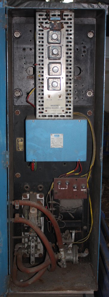
Also another project, oh joy. Since it needs quite a bit of restoration work before it will be usable. Oh well...
'Tomorrow' (Friday) didn't happen. It rained in the morning, and the seller wasn't able to extract it from behind the piles of other things in the yard. On Saturday things went better, and in the afternoon I went to collect it.
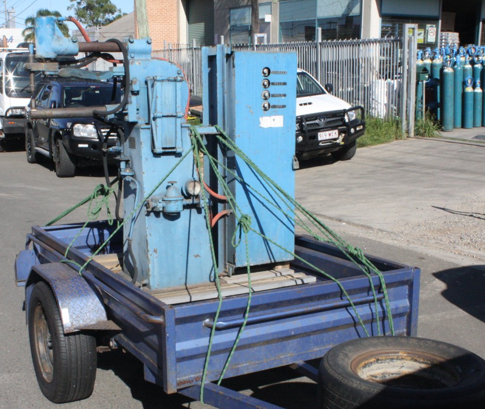
Here it is, forklifted onto my trailer and tied down. →
Only about 12 Km distance from home, but driven very, very slowly.
 |
 |
 |
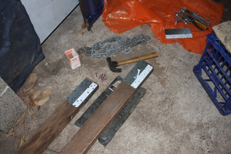
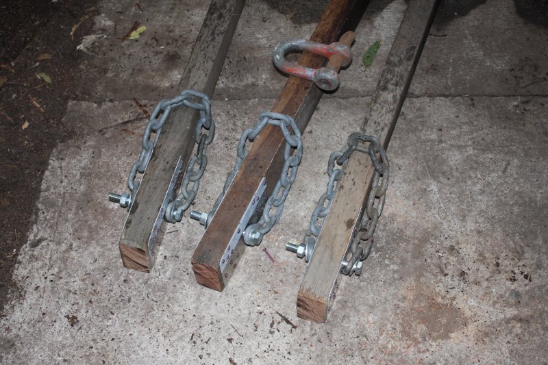
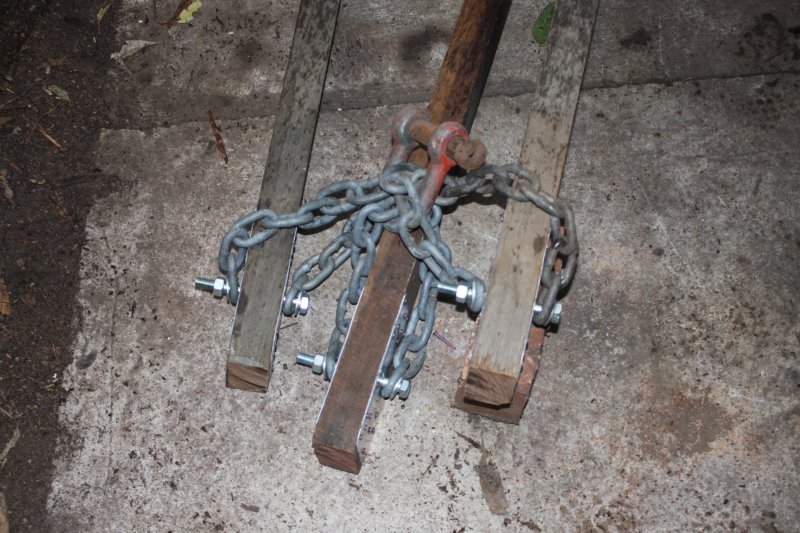
Lifting it off the trailer was a job for the next day. So of course on Sunday it rained on and off all day. But it still had to be done. This 'lift something heavy, somewhere in the back yard' is a problem for which I need a general lasting solution. Decades ago, in another residence I'd made a simple tripod hoist to extract a car engine. I think I'll do the same again here. But a bit bigger, since this spot welder on the trailer is quite high.
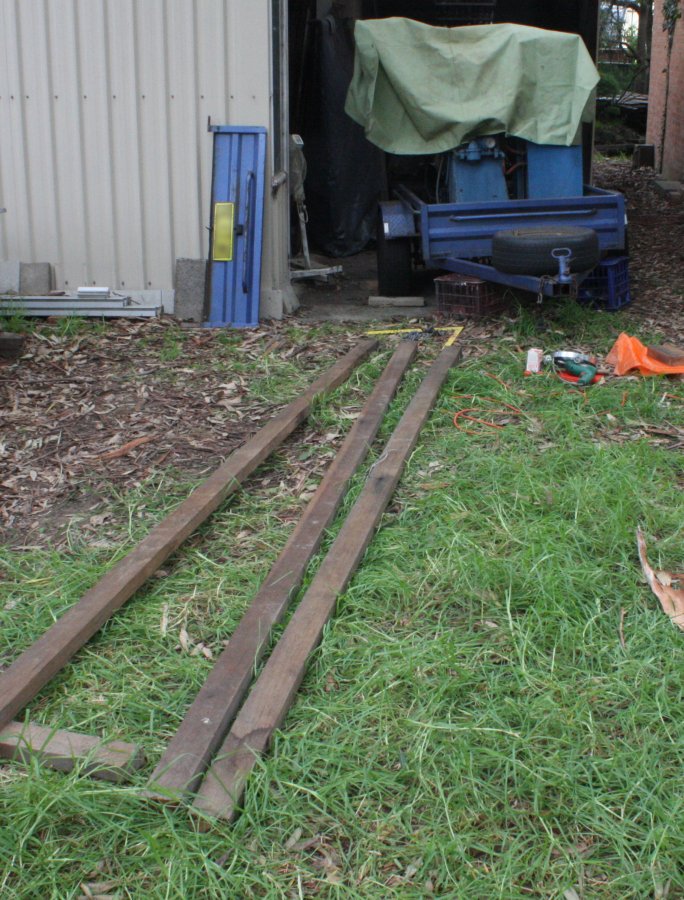 |
 |
 |
 |
 |
1. Fortunately I have a lumber pile including several good long and solid hardwood 2x4s. I pulled out three that will do, though two have a bit of curve.
2, 3. The tripod apex needs to be flexible. A simple solution involves bolts through the timber and chains. My earlier one was light weight (an engine isn't all that heavy) but for this one I want to eliminate potential disasterous/lethal failure modes like the timber splitting endways around a bolt hole. Hence nailing on reinforcing steel plates on both sides of the beam ends.
It started raining more heavily around then, but fortunately I have a covered work area I could move to.
4, 5. The idea is to loosely link the struts together, and also provide a single lift point. This was the trial arrangement, but in practice I'd made it too loose and later had to shorten each chain loop by 4 or 5 links. Easily done by changing which link was attached to the bolt.
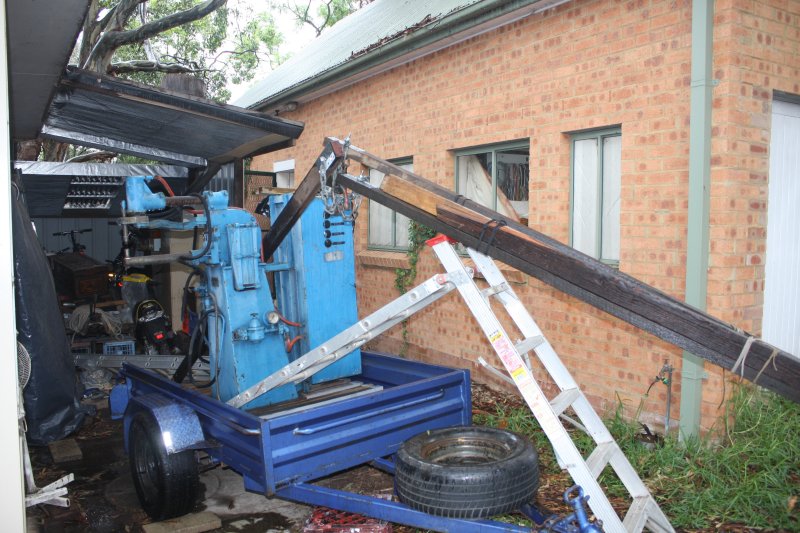 |
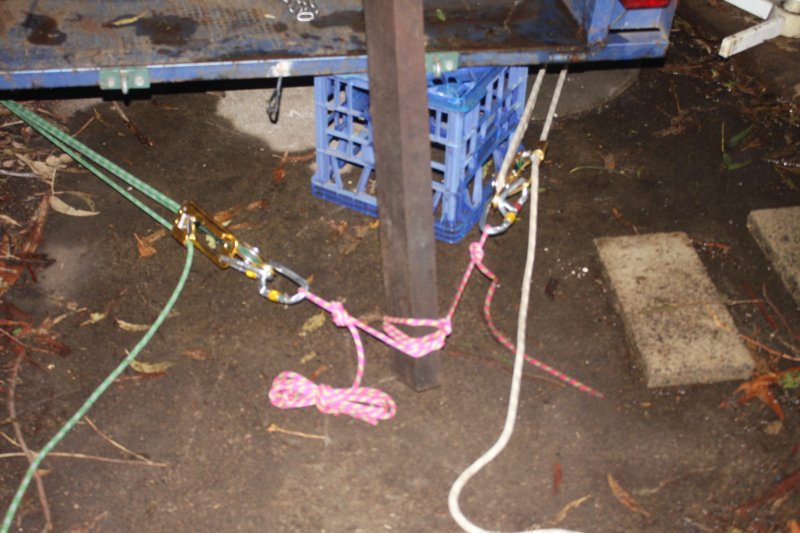 |
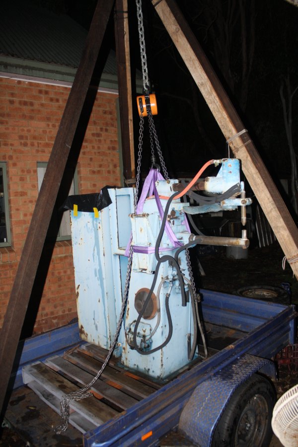 |
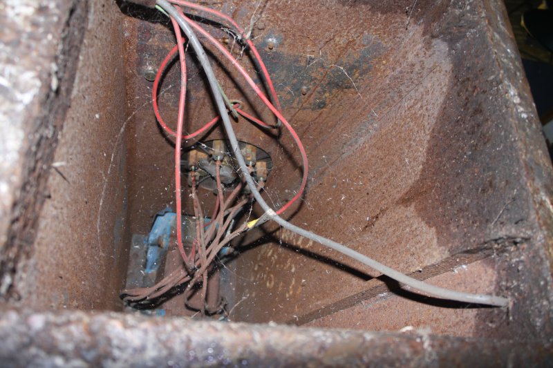 |
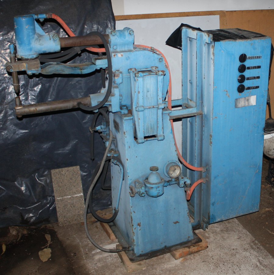 |
1. The next problem wasn't anticipated. My lightweight tripod years ago was easy to erect — just lift it up. Not so much here. These hardwood beams are heavy, they are also now wet from rain, and with the two bowed ones I'd lashed on stiffener beams (softwood) to make them straight. And the whole thing is much bigger than my earlier small tripod, so to get it anywhere near 'up', the apex is quite high. Well above my reach, even standing in the trailer.
End result: I found I couldn't lift it into position. Not even close.
2. The rather comical solution. Lifting gear used to erect the lifting gear. I used some of my rock climbing kit to rig block and tackle winches between the 'feet' of the tripod. Then just incrementally forced the feet of the triangle inwards, hence forcing the tripod apex upwards. This was where I discovered the chain loops were too long, making the apex interconnection too floppy. More stuffing around, leaning the whole thing against a workshop flat roof, using G-clamps and rope to secure the apex junction while I removed and adjusted the chain linkages, then getting it all going again.
3. Everything finally in place (after dusk) and taking the weight of the spot welder. I didn't have any idea how much the spot welder actually weighed, so wasn't sure my little 1 ton chain hoist would handle it. It turned out to be adequate.
4. I'd been wondering what the inside of the base looked like. With the spot welder hanging in the air and the trailer removed, I could take a look. Not feeling very comfortable about sticking my hands and head under this hanging monster, I took a very few quick photos. Discovered that the power control, that I'd assumed might be some kind of variac, is actually just a big 6-pole rotary switch. Selecting different taps on the main spot welder transformer.
The selector shaft is seized, but that won't be hard to fix. Also, cloth-insulated wiring, great. What condition is the transformer primary in I wonder? Some kind of lengthy warm bake-out would probably be a good idea. The secondary... ha ha, that is fine. The single turn secondary consists of the enormous cast brass outer casing of the transformer. That structure you can see in the external photos. It's probably the single most indestructible 'electrical' component I possess. Could do with a new coat of paint, is all.
5. Down! This is not its final location, but it is where it will sit while being restored. At least it's under cover and out of the weather now. It's soooo heavy. Even to move it a couple of meters over level concrete, I had to crowbar and wedge it up onto metal tube rollers, and work it across in small steps. Trying to drag it by hand just doesn't work, nor did even 'crowbar walking' it.
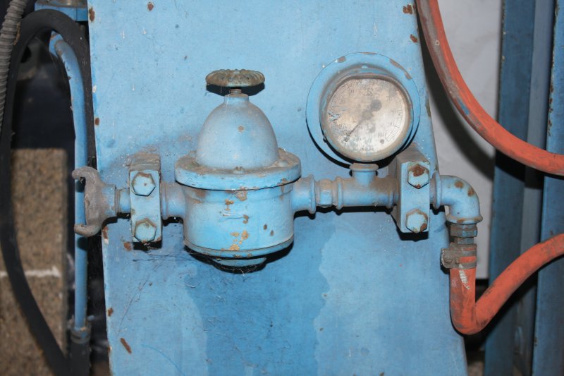 |
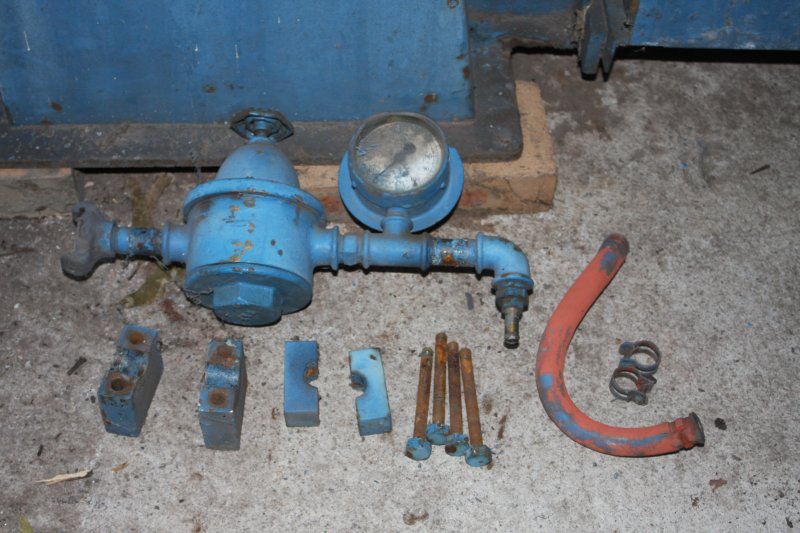 |