The last week has been a humbling reminder that my welding sucks, metal doesn't like me, and I should give up any pretense of being able to plan things or estimate how long tasks will take.
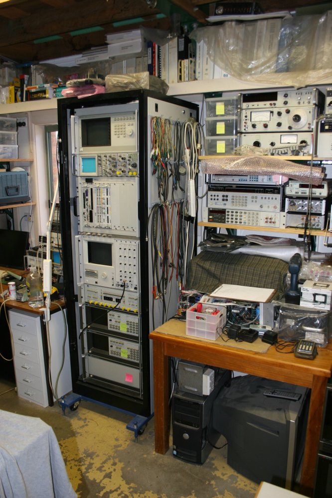
Previously I've mentioned a rack of equipment I've been constructing. See Heavy duty procrastination, Rack roller base and An actual knob.
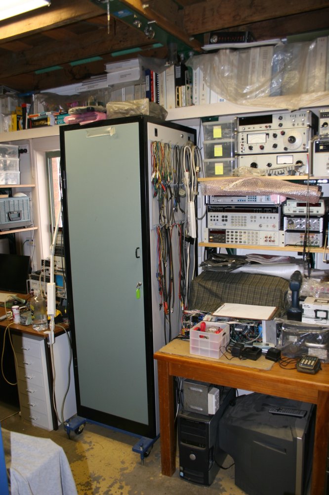
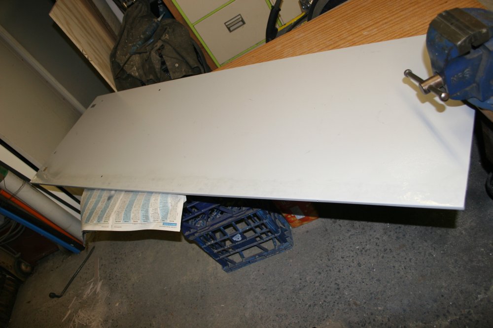
After I 'shrank' that rack, of course the original top and side panels no longer fitted. That was OK; I'd assumed I'd just use it without the panels. They're fairly thin, painted sheet metal with folded edges, which means that reducing them in size to match the new size of the rack would be a lot of work. Or flat out impossible for me, since welding thin sheet metal is a skill I don't have. Some people seem to be able to do it, but whenever I've tried to weld sheet metal edges the result has been horrible.
Something essential in any electronics workspace is a row of hooks on which to hang assorted test leads, alligator jumpers, coax cables, etc. For a while I've had some test lead hooks on the 'wall' (actually it's a large door that rarely needs opening) off to the left of the main bench. But that isn't very convenient to reach, and now I'm going to construct a set of shelves there for an assortment of gear like battery chargers, laptops, phone charger, NAS unit, and so on. So the cable hooks have to move.
But to where? There's no free wall space left anywhere in this room. Hmmm... Well, I could use the sides of the new rack. That would be an ideal place for hanging cables, since the rack is right between the two work benches.
Sigh... If it actually had sides. But it doesn't, because the old side panels no longer fit. Could I make them fit? Urrgh... I know what will happen if I try to butt-weld thin sheet metal. Nope...
Something that would work would be to just buy some sheets of plywood, cut them to size and screw them to the sides of the rack. Then screw hooks for the cables into the plywood. But that would look rubbish. Besides, there's that word 'buy', which I'd rather avoid if possible. Especially when I have nice metal sides (and top) that are fine except for being the wrong size now.
OTOH, would plywood look more crap than if I tried to hack the metal panels to size? Maybe not.
So I hunted at the hardware store for suitable solid screw-in hooks. And there were none! Which greatly simplified the decision. If I want hooks on the side of this rack, I have to shrink the metal panels to fit the shrunk frame.
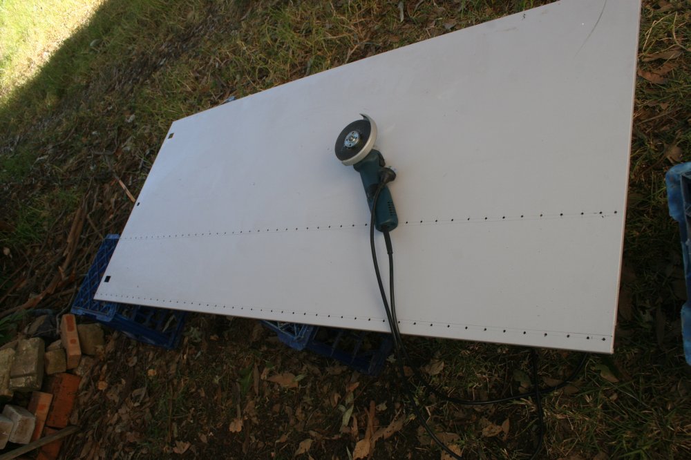
Watched a few youtube videos on welding sheet metal, then began. As a trial I tried doing the top panel first.
Cutting out a section was easy, the cutting disk in an angle grinder slices through thin sheet steel very rapidly. Also it's easy to accurately follow a line, since the disk is aligned by its own cut. The surprise was that clamping the butt seam, tack welding along it, then closing the whole seam, actually worked! There's some bowing of the flat face but it's not too bad. After grinding the weld flat and painting, it looked quite good. So suddenly I was thinking I knew how to weld sheet metal.
Ha ha! Stupid me. That weld was right next to an edge fold, which meant the weld line couldn't bow up and down much. Also one side piece was narrow, and would move with the metal expansion and contraction in the plane of the sheet. I knew that, but somehow didn't apply that to thoughts of hacking the side panels.
So it began. "This will only take a little while. Couple of days to finish." Ha ha ha ha....
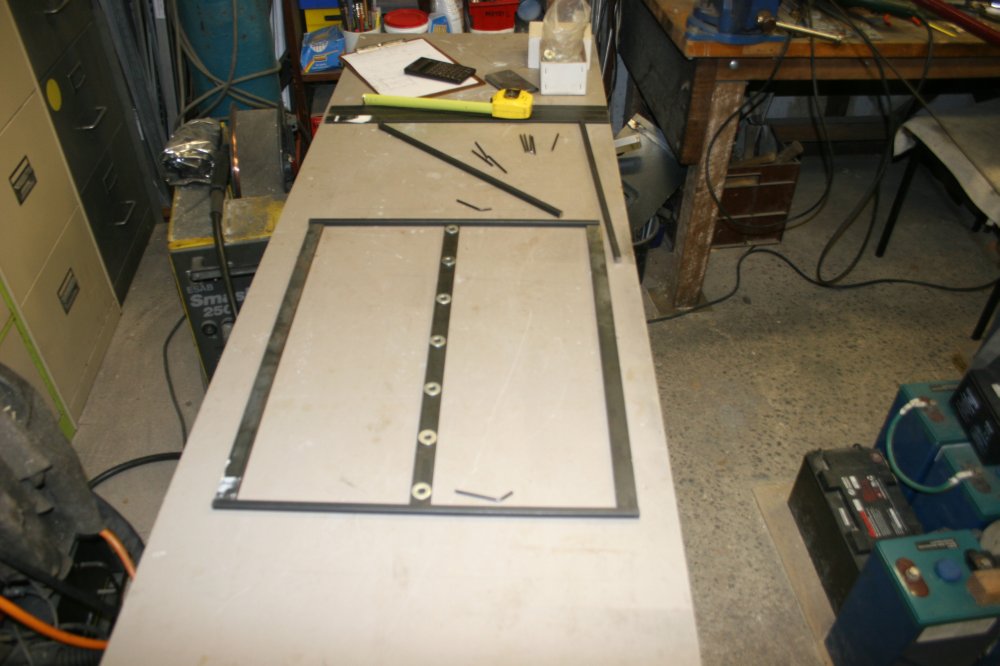
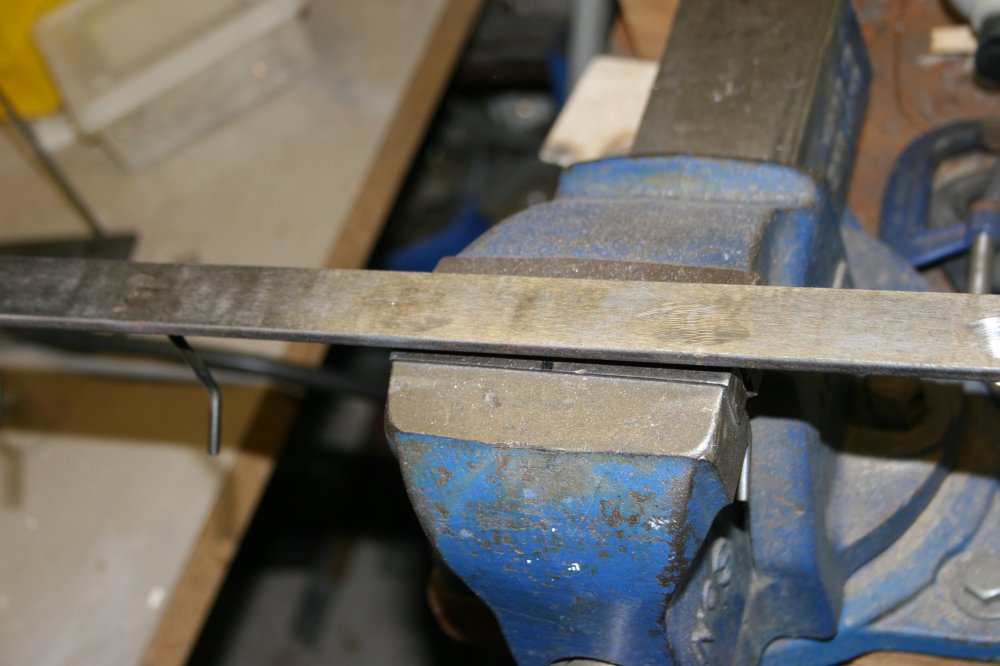
Cutting out the required amount of the panel was easy, nice clean straight cuts by eye to a line, with the angle grinder.
Used a paint stripper disk in the angle grinder to clean the metal along the weld line. Clamped the pieces for welding. I was confident and rushed enough that I didn't take photos of the first welding attempt, or I should say, miserable failure. Started to tack weld the seam. Tacked the ends, middle, then a few more spots — still OK at this point. Then started doing short sections of continuous welds, alternating back and forth along the seam.
And... NOPE. You know that 'rolling green hills' Microsoft background? Like that, only not green. Bugger. That definitely didn't work. Disgusted, I quit for the day. Next day used the thin cutting disk and grinding wheel to slit the welds open again and grind the surface of the two pieces back to flat. The metal went fairly flat again, thankfully. Still no photos at that point — too ashamed!
Did other stuff for the rest of that day, while I thought about it. Am I doing it wrong, or is welding a long straight butt seam on thin sheet metal impossible? Watched some more youtube videos by sheet metal professionals, about this kind of thing. In general it sounds like they expect to be doing quite a bit of panel beating with a hammer and dolly (big lump of metal as a backing mass to strike against) after welding. Ha. That may be fine for car body panels, where imperfections can be hidden with filler and the sheets are curved so have some ability to hold their shape. But I don't think it's going to work on a large flat sheet. So no, let's just assume it's impossible — this way.
The alternative is called a 'cheat' by a lot of the youtube sheet metal experts. But who cares what those guys think?
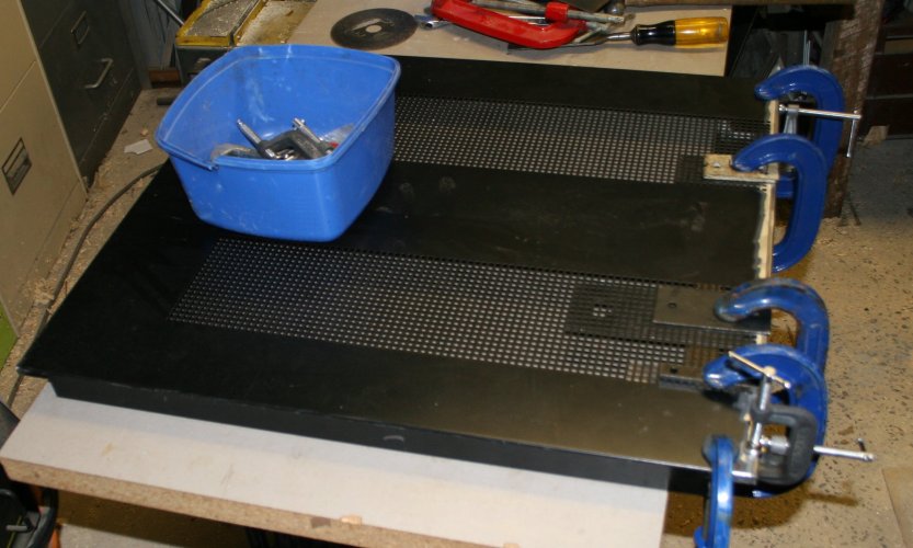
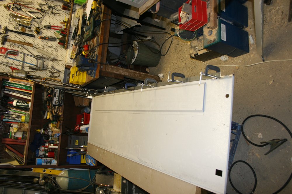
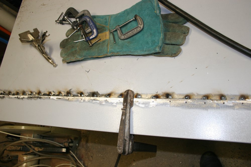
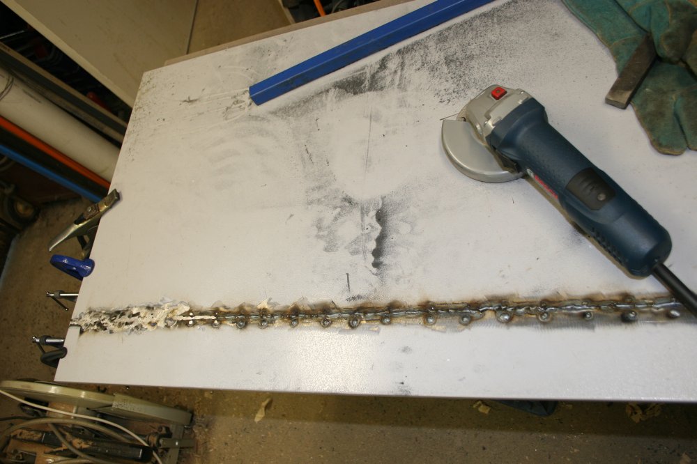
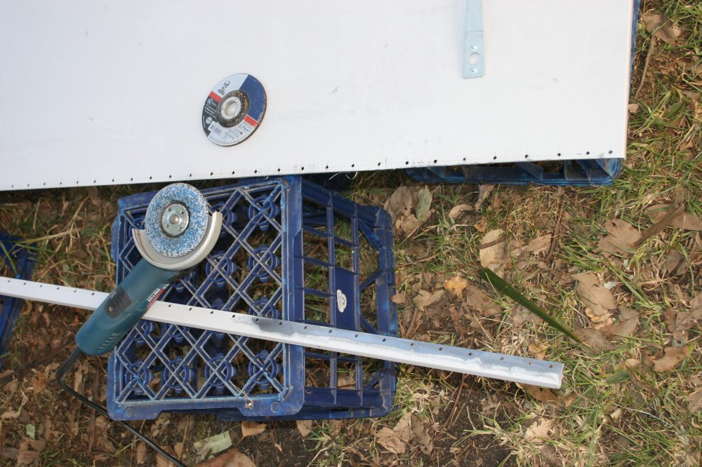
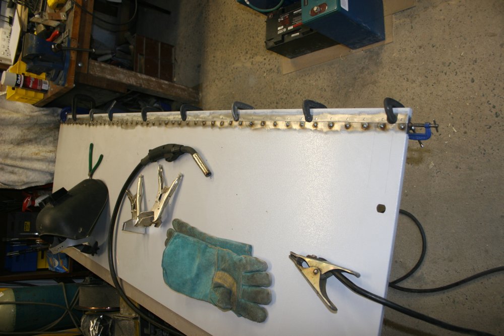
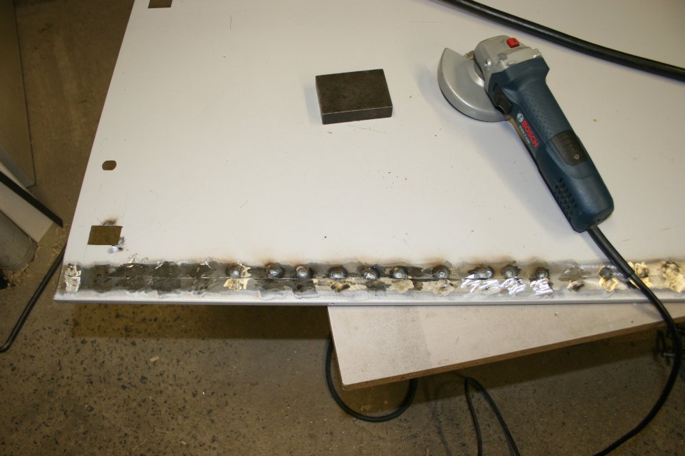
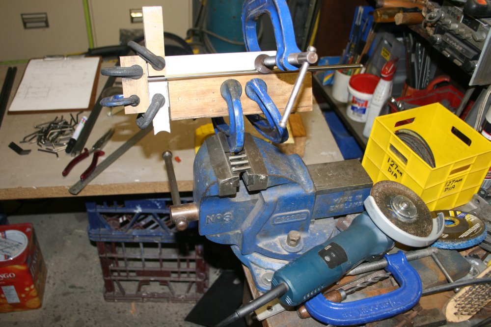
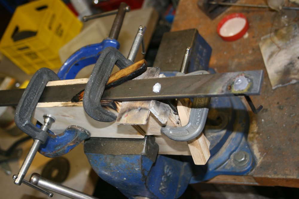
I decide I'll try it with a backing strip. So after a trip to the local steel warehouse for some strips of 3mm thick by 25mm black steel, it's time for Take 2. This time with photos. (Click thumbnails for full size.)
|
|
|
|
|
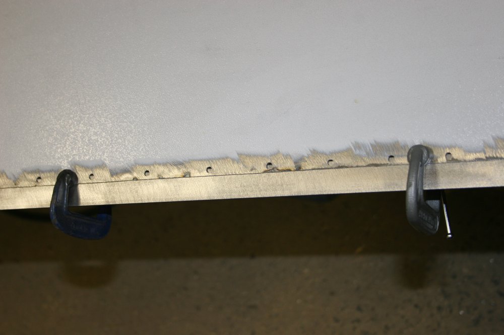
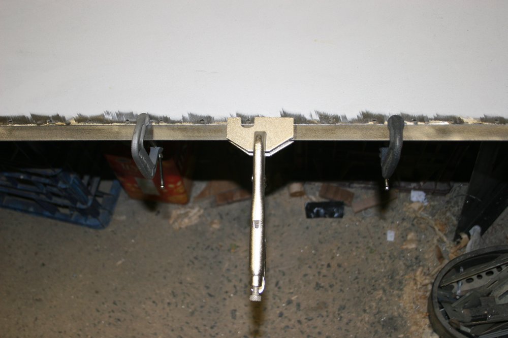
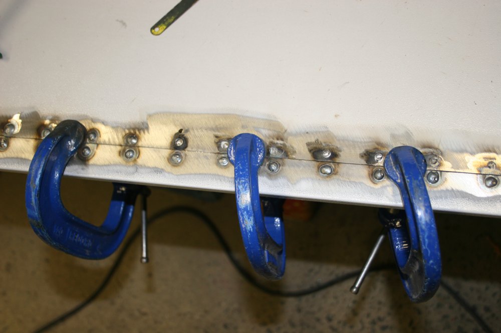
The idea with a backing strip is to have a line of plug welds through the sheet metal to the strip, along both sides of the seam. Plug welds are done by drilling a hole through the sheet, then filling that with weld metal that also bonds with the backing strip. As the plug of weld metal cools it doesn't pull the sheet sideways since the contraction is even in all directions in the plane of the metal sheet. Hence no bowing.
Well, not so much bowing. There's still a net contraction on one side of the backing strip, so the whole sheet will tend to curl evenly. But this can be flattened by just evenly bending it the other way.
The pics above were setting up for plug welding one side of the seam. The result was OK, so on to the other side.
|
|
|
|
|
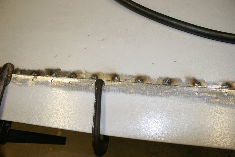
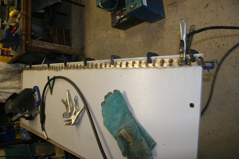
So far, OK. There was still some bowing, mostly left over from the original stuff-up, but acceptable.
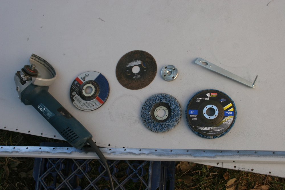
I should mention that my welding mask is an LCD auto-darkening one, but cheap and crappy. It tends to darken a bit slowly sometimes (so I get briefly blinded by the initial flash), and when dark seems to have poor contrast. Also I need to wear glasses, and under the mask they tend to get out of position. Net result is I sometimes can't see very well around the arc. So I tend to miss. With the plug welds that means some of them didn't quite fill one side of the hole. No matter.
|
|
|
|
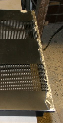
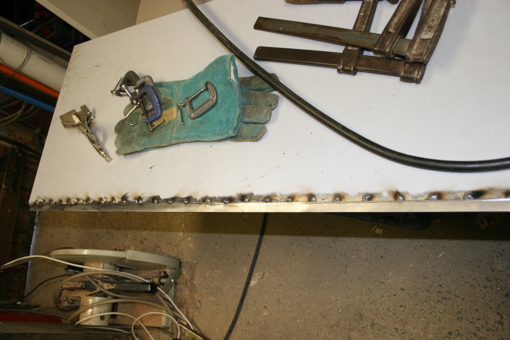
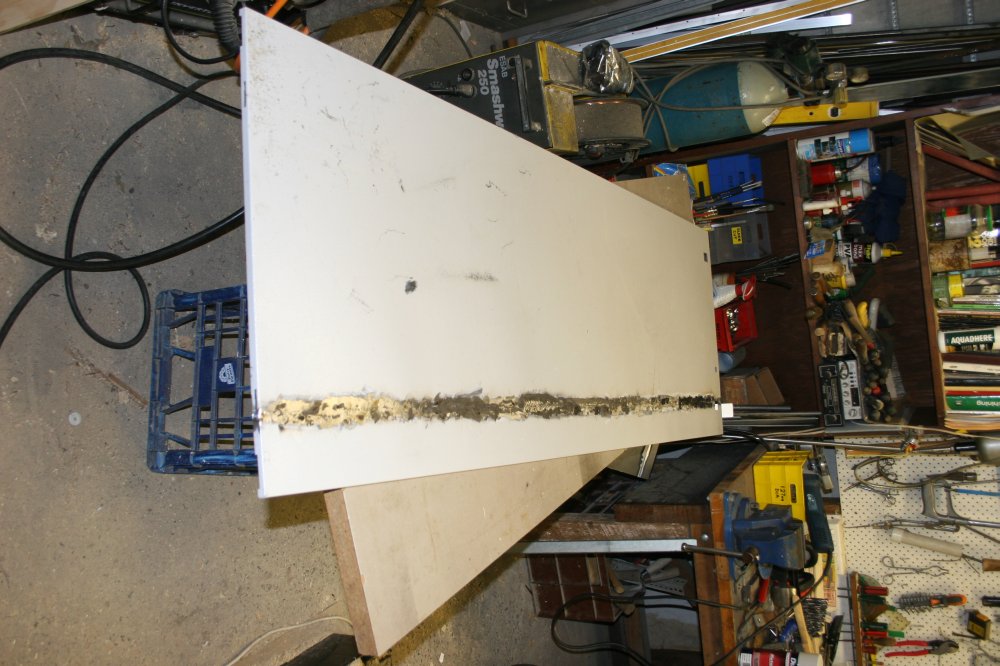
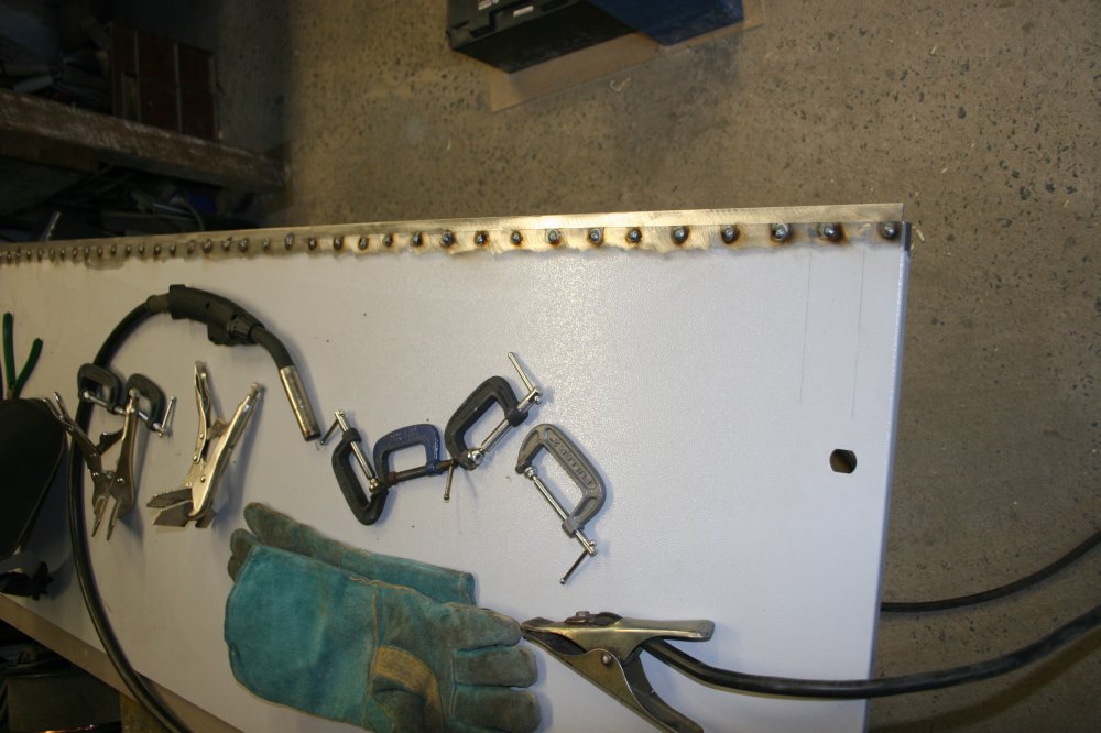
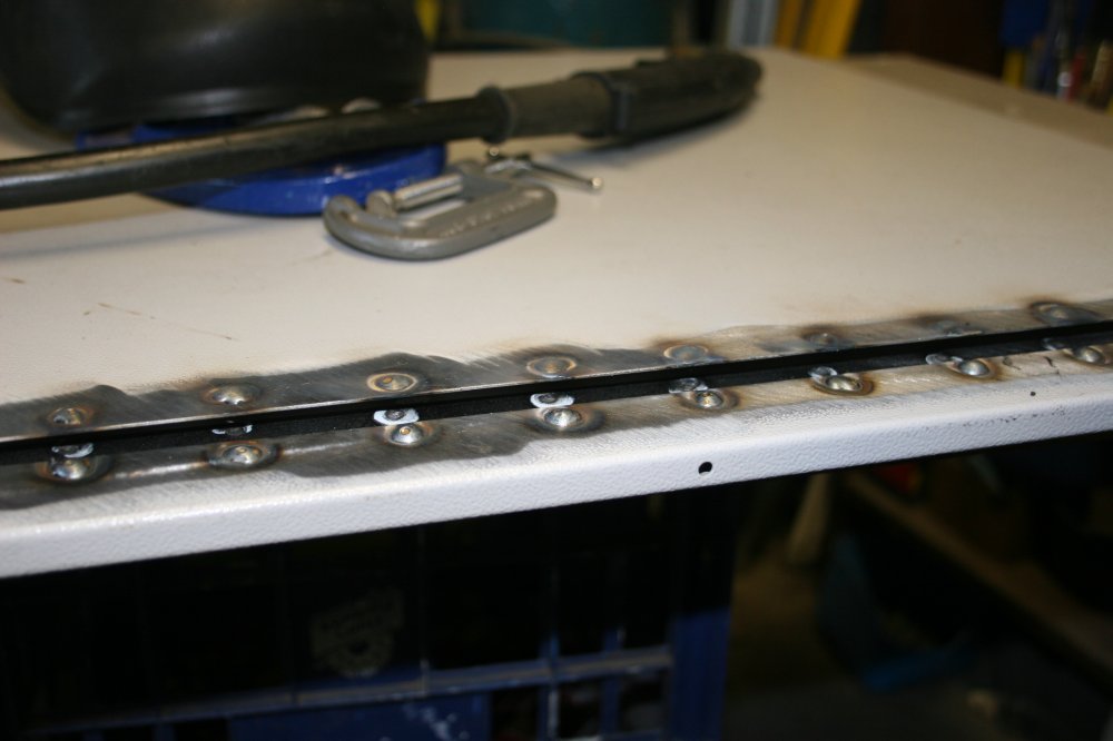
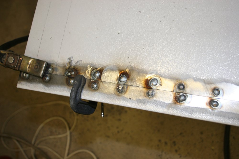
I still had the idea that I wanted a continuous seam, and figured that with the backing strip holding things in place it would be worth trying. So I welded the seam, again doing it in short segments, switching back and forth along the seam.
And it worked, kind of. It added a lot more bow during the welding, and in fact was enough to break some of the spot welds holding a sheet metal stiffener piece to the back of the door. Once it all cooled down the bow wasn't too bad and I reattached the stiffener to the main sheet with a few small spot welds.
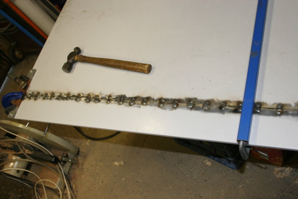
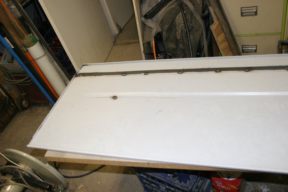
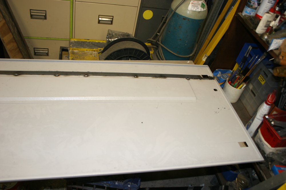
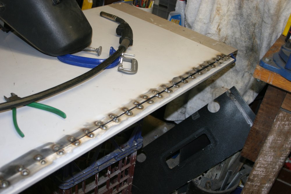
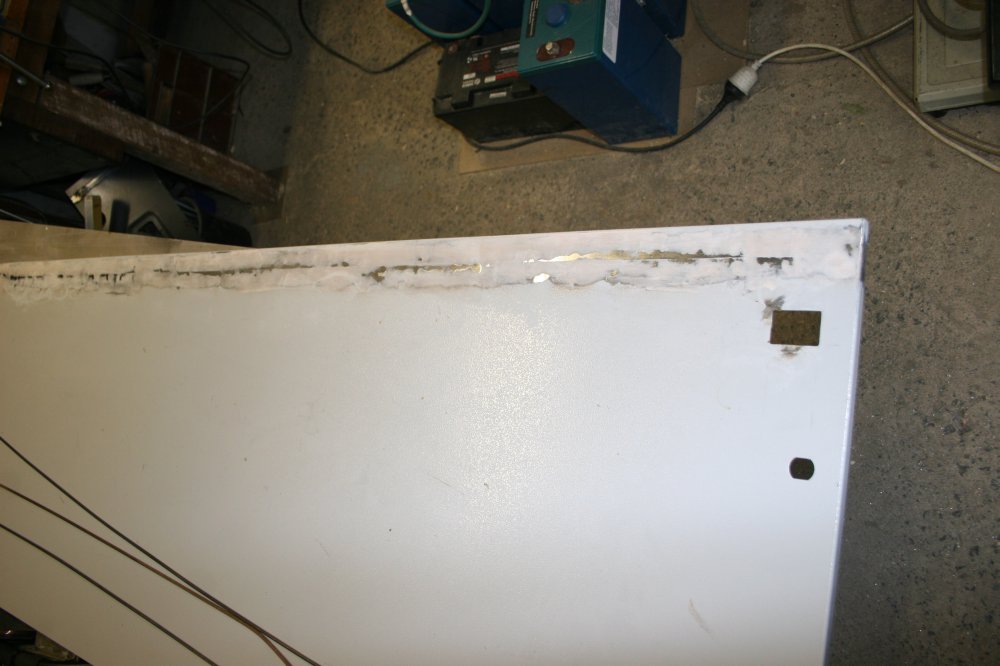
The down side of the welded seam was a great deal of extra time required to grind the surface flat. I decided that the other side panel wasn't going to have its seam welded. After grinding it didn't look too wonky, and the panel fitted in the rack OK. I knew I had a tin of epoxy body-filler somewhere, but couldn't find it after some searching. Also by now this 'short' project was already badly blown out, so on the 'bugger it, it will do' principle I just spray painted it as-is. Which turned out to make the assorted weld holes and missed spots in the seam weld stand out like sore thumbs, since they wick the wet paint in. Oh well... I consoled myself with the thought that this botch-up job would eventually be in shadow and hidden behind a veil of hanging test leads.
Time to get started on the other side panel. Hoping to get that one right, since it would be the left hand one, and visible from my main workbench seat.
|
|
|

|
|
This time I shifted the cut-out away from the internal stiffener rib. Which meant I'd have to cut a new hole for the retaining catch, but that's easy. Also this time (hindsight) had the sense to drill all the holes before separating the two pieces. This stage went a lot faster than the other side had. Clamped the backing strip on, and quickly did the first row of plug welds. Yay! Getting better at this. (Ha ha ha no.)
|
|
|
|
|
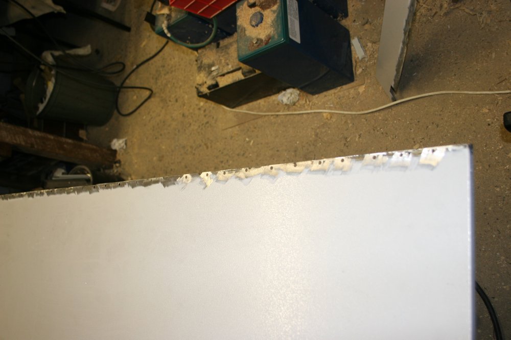
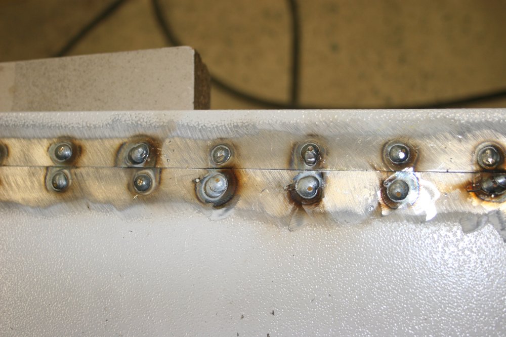
Clamped the other piece on, quickly and efficiently welded all the plug welds along that side. Hey, this worked really well, there's virtually no bowing, it's all nice and straight and neat. Feeling quite pleased with myself I removed the clamps and grabbed the edge to lift the panel up. SPANG! About half the plug welds popped open.
Oh. Uh huh. Do not feel pleased with self. Apparently my 'quick and efficient' plug welding was just a little bit too quick this time, and often wasn't hot enough to melt into the backing strip.
So that makes for an awkward problem. Some of the welds are solid, so what do I do now? I'd made the holes a bit smaller than I'd like too, due to the narrow backing strip, and that was another factor in this failure. Needs bigger holes and more weld heat. But drilling out the welds... with the whole thing still together... ouch. Also a standard drill bit tip camber is pointy enough that drilling through the panel sheet at the hole edge, will put the drill tip through the backing strip. Hmm...
In the meantime I worked along the seam, applying bending force to each pair of welds. Some more of them broke. I marked all the bad ones, then re-clamped the whole seam. The drill problem was solved by grinding a drill bit face to a much flatter angle. The original holes were 3/16", obviously too small. The second attempt used 15/64".
|
|
|
|
|
Drilled out the bad welds with the larger drill, set the welder to the next higher current, and re-welded several of the new holes. At least this time I had the sense to test the welds before doing all of them.
Annnd... nope. Some of them are still bad. I'm starting to wonder how many of the plug welds on the first panel were bad.
So this time try a 5/16" hole - which means re-grinding the point of another drill. Fortunately I have a box of old drill bits for just this kind of thing, so am not mucking up points on my good drills. After drilling out again the welds from the last test, this time the trial welds are good and I do the rest of them, then grind flat.
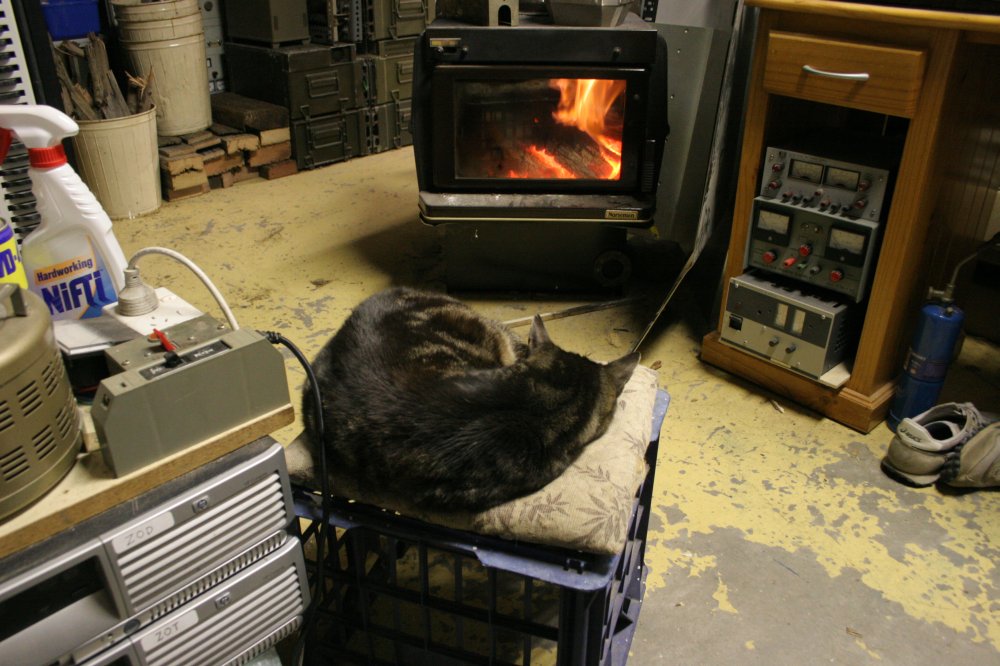
Finally done. My entire workshop development is supposed to be for the purpose of spending my retirement years in pleasant pottering on some projects I've wanted to do for a long time, and had better try before I get too old. But after this debacle I'm wondering if I should just skip straight to the dozing in front of a fire stage, like my very old cat Dusk. She's 18, and probably doesn't have long to go.
|
|
|
|
|
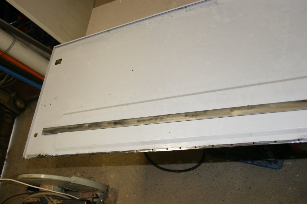
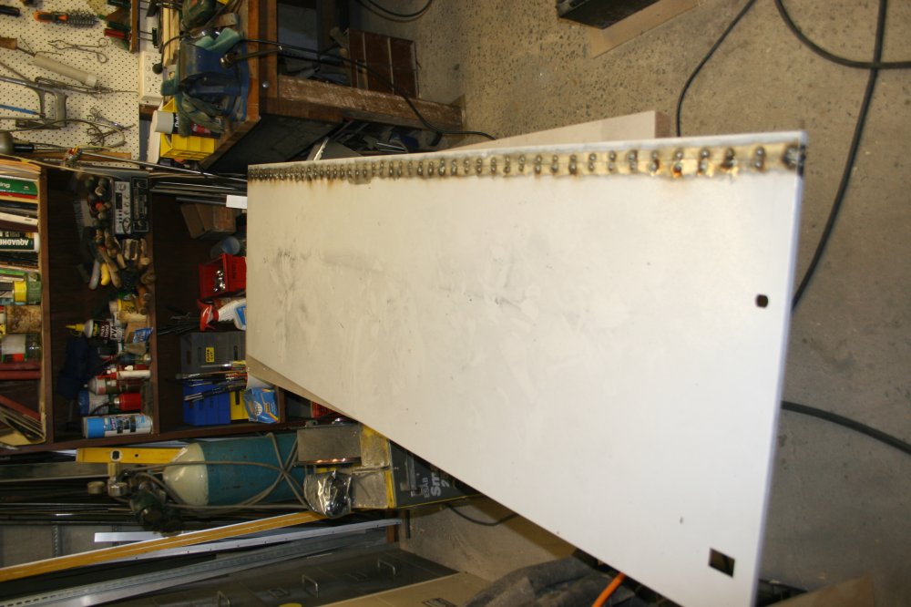
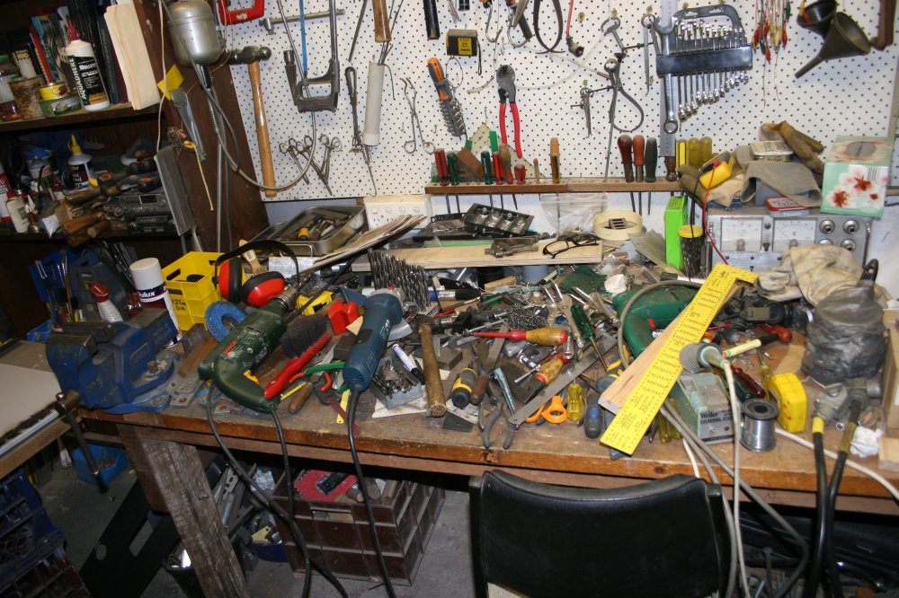
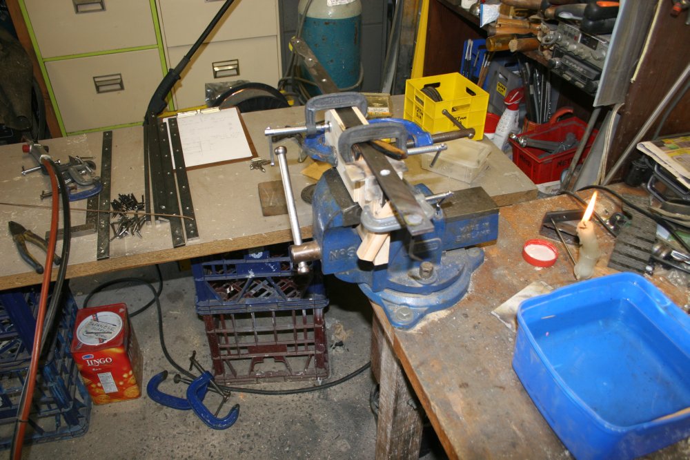
By now the workbench was getting quite messy. I rarely tidy it while in the middle of some job, and this one is not over yet. In the meantime that tin of body-filler had turned up, so this panel could be finished off much neater than the first. At least that worked as expected. Also I somehow managed to not totally stuff up cutting a simple rectangular hole in the panel for the top retaining clip. (I only stuffed it up slightly.)
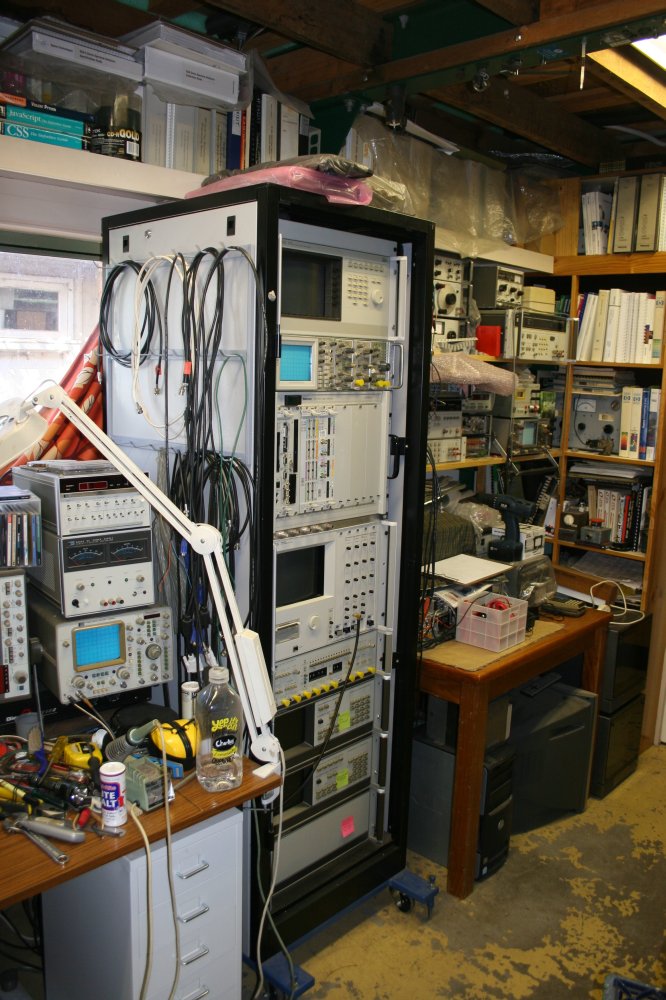
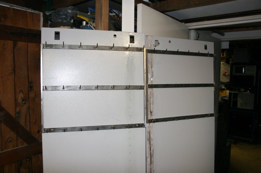
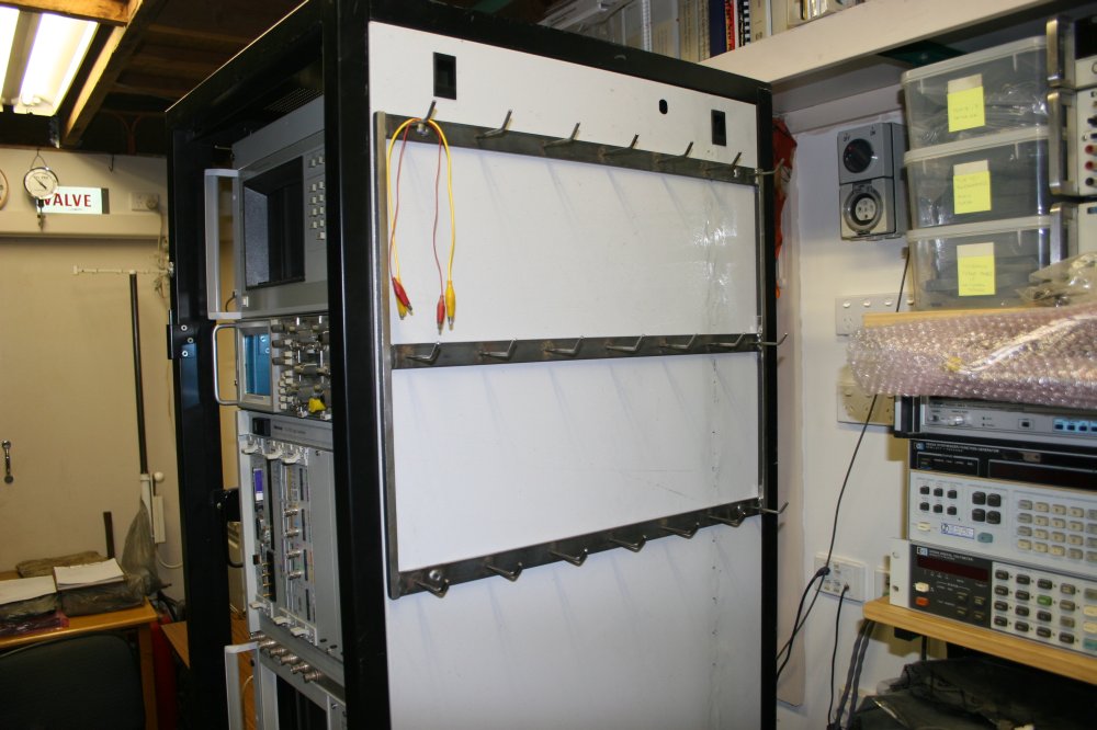
The next stage is to make the test lead hooks. I wanted to have the hooks on a frame that could be removed easily from the side of the rack if needed. The rack is on rollers and is intended to be movable. Hooks and cables on the sides might be a nuisance during moves.
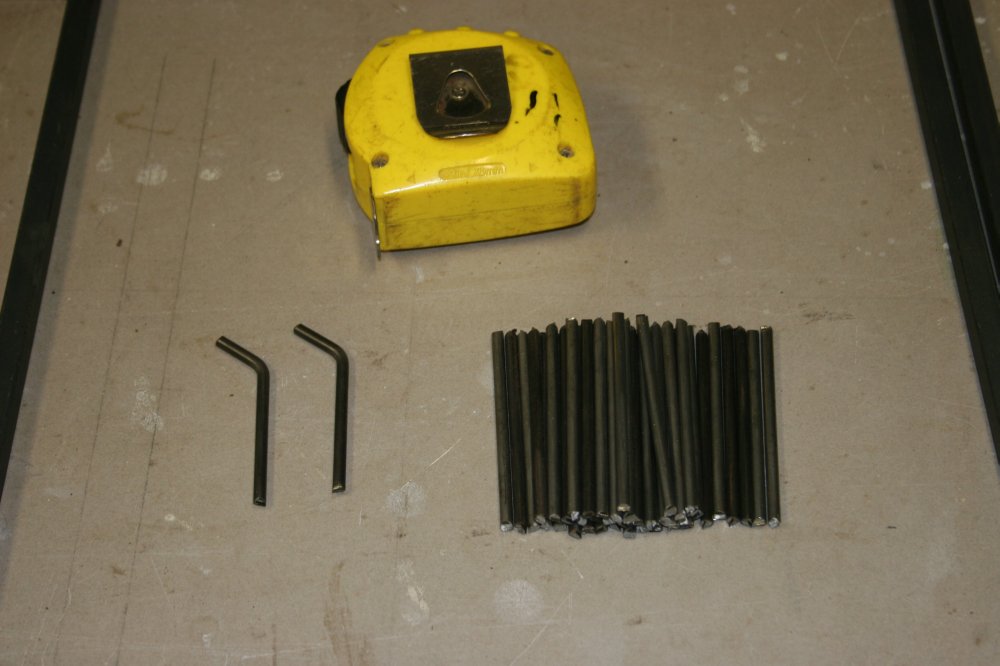
It's cool to find a common but unnoticed source of something really useful for free. For the hooks I wanted some form of very tough steel wire, that would not bend under possibly quite heavy cable bundles. I could buy thick 'piano wire', or... I could use a discovery I made years ago, and can always easily get more. There's some visible in the second pic above.
Mattresses are bouncy, right? You've seen the insides of them, and know they have lots of wire springs. But did you notice they also have stiff straight spring wires along all the edges? These are typically about 4mm thick, and very resilient. Also all the other wires are just looped around the edge stiffener wires, not actually bonded to them. So these straight wires are easy to extract. You need a sharp knife and a pair of bolt cutters with hardened jaws. Slit open the mattress cloth covering at the corners, cut the straight wires free of their corner bends, and they just slide right out easily.
So every old mattress you see tossed out somewhere is actually a resource of really nice, useful springy straight thick steel wire.
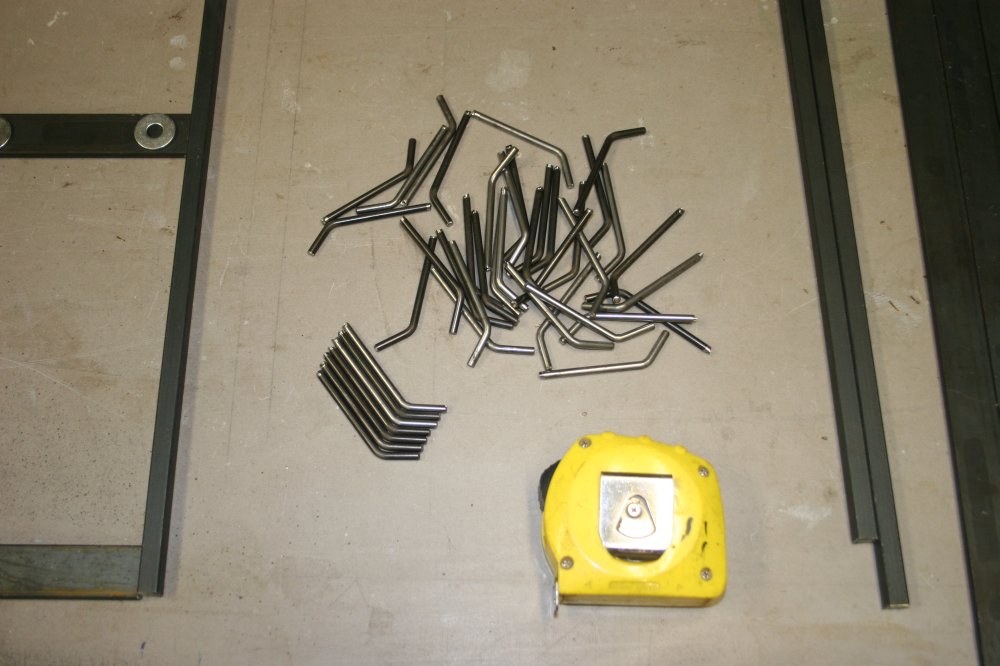
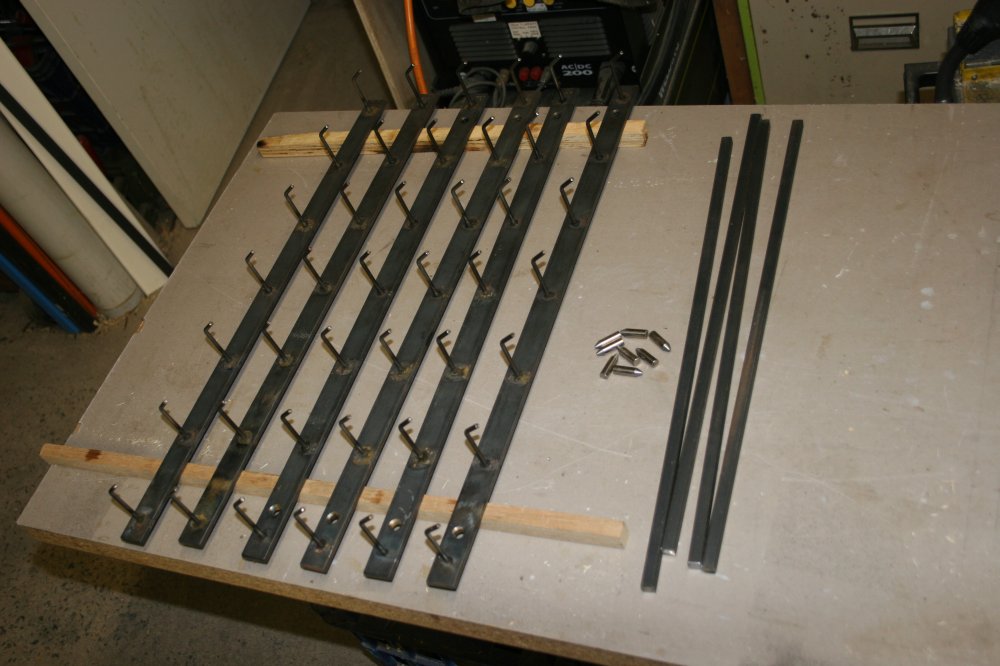
The hooks frames were easy, using leftover mild steel stock I had lying around. Two frames, three rows each, seven hooks to a row, makes, ha ha, nice coincidence! 42 hooks. Clearly the answer to my cable storage needs, if not everything else too.
Being such tough spring wire, it's quite hard to cut. Cutting 42 pieces to identical length required an improvised jig. Bench vice, G-clamps and bits of wood, plus the bolt cutters. Bending them takes some hard hammer whacks with the wire in the bench vice, using the first one as a bend angle template.
|
|
|
|
|
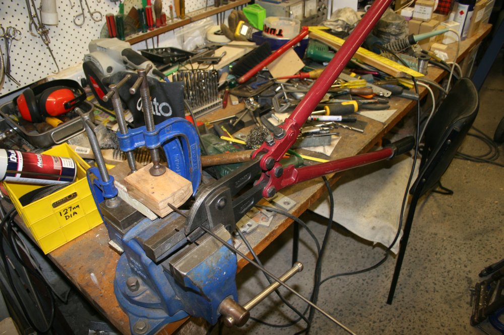
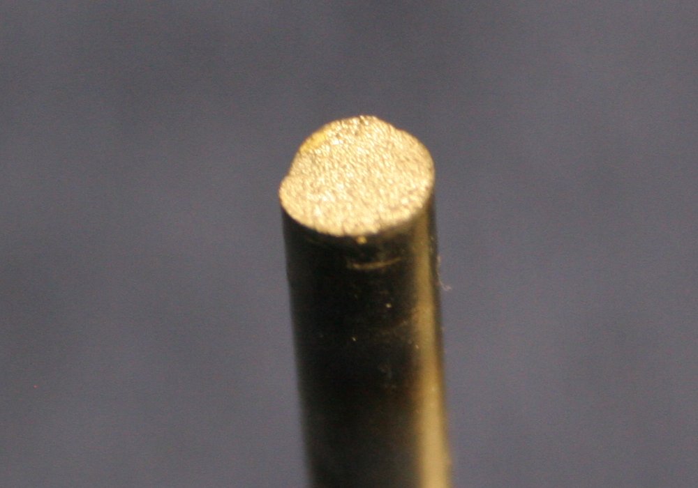
For attaching the hook-racks to the side panels, I'd decided to use a pin system. For this I needed several short pins cut from an 8mm dia polished steel rod. (Which was salvaged from an old printer.) Pic 2 above is a jig for cutting the pins using an angle grinder and thin cutting disk. It's all just wood scraps held together with G-clamps. Some cut pins sitting on the vice jaws.
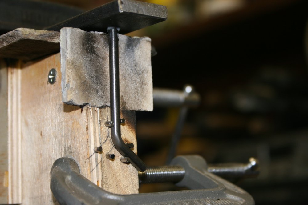
The next stage was supposed to be simple, so I didn't take photos. Each of the horizontal bars has 7 holes for the hooks. There's a countersunk hole at the back, and the intention was to position each hook accurately in a jig, then weld the hook wire end into the countersunk hole. They'd be ground off flat later.
I made the jig, then started welding hooks. Something (maybe the experience of my earlier stuff-ups) made me stop after doing two hooks, to check the weld strength. I pulled the bar out of the jig, and grabbed the first hook. Was going to try really heaving on it, to check it was as strong as it ought to be. But before I applied barely any sideways force, it popped free with a nasty 'snap' sound.
Oh great, this again. Bad welds? I tried the second hook. It too snapped loose with a light effort. Hmmm... Looking at the wire end it was obviously not the weld that gave way. The wire itself showed a brittle fracture, with a typical crystaline 'frosted' surface texture. Granular failure, an alloying/temper problem. Sigh. But I've often heated this same wire up to red heat and cooled it again and it doesn't do this. For instance with silver soldering, it's still just as strong as before. Whyyyyyy?!
After thinking about it I realised the problem is not the peak temperature, but the rate of cooling. With silver soldering a large metal area is heated to red heat, then cools down slowly by itself. But when arc welding just the wire and the metal adjacent, the weld cools down very fast. Apparently, doing something nasty to the grain structure of this spring steel wire. It becomes extremely hard, but brittle.
And so now there are two small pieces of very hard steel in the bottom of those welds. I tried drilling one out, and sure enough that isn't going to happen. Instantly blunted drill bit. Great. But they have to come out, and also I don't want to ruin the nice press-fit holes for the hooks.
Fortunately I had a high grade steel pin punch, that fitted in the holes. Ground off the excess weld metal bump, then putting the mild steel bar on the bench vice with the 'bad bit' above the open jaws, simply bashed the nugget of hard steel wire out through the softer weld metal by brute force. Then redrilled the countersunk hole. All good.
But how to secure the wire hooks? Oh no, am I going to have to silver solder them all? That will be so much work...
Which is what I had to do. Painful. For one thing the process of adjusting the bar in the jig to do each hook was lengthy enough that leaving the oxy torch going the whole time was too wasteful of gas. So that's 42 cycles of 'set hook and bar in jig, apply flux, light torch, adjust, do silver solder, shut down torch'. But also, silver soldering heats the whole bar around the joint up to red heat, so the all-wood jig had to be modified to take the heat. That involved cutting out some wood and replacing it with fibro sheets. The bar was held in place in the jig with a wooden wedge, but that was close by the weld point. For arc welding it would be OK, but an oxy torch flame would burn it to nothing very quickly. That was solved by soaking the wedge in water (it still burned, but lasted for the job.)
|
|
|
|
|
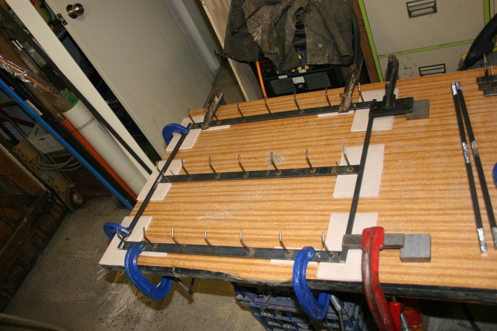
Eventually, all six rows of hooks were done. Well, apart from soaking in water then wire brush scrubbing to remove the silver soldering flux.
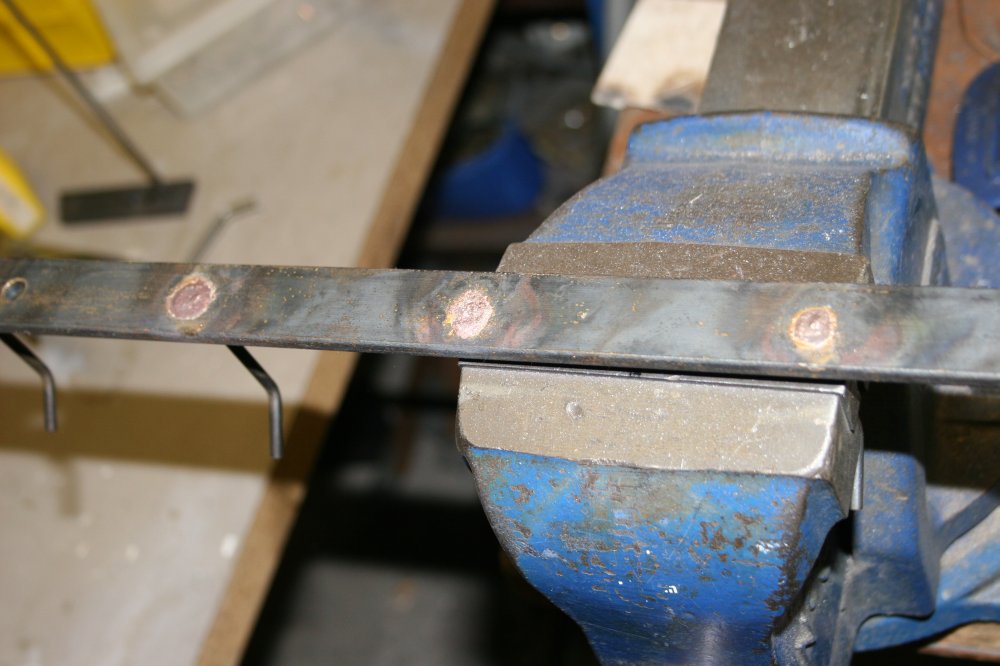
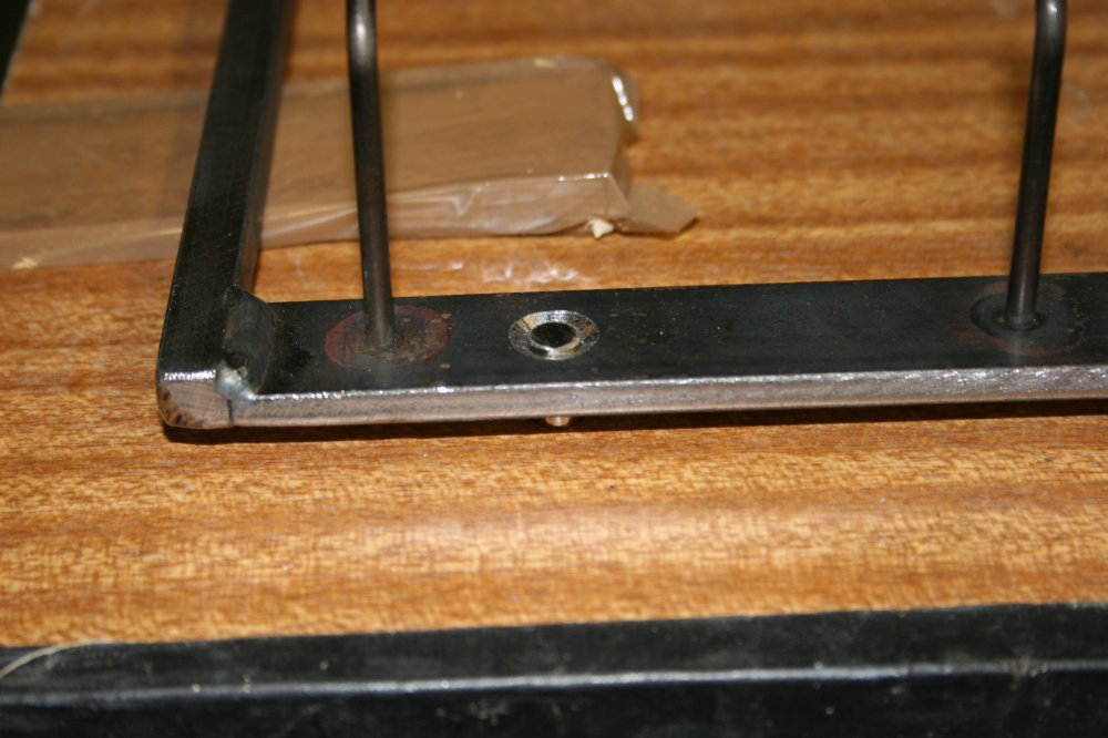
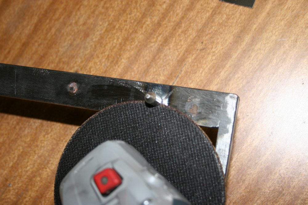
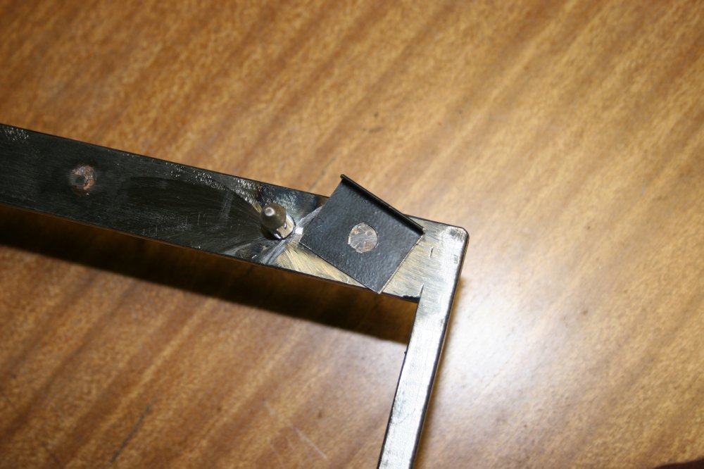
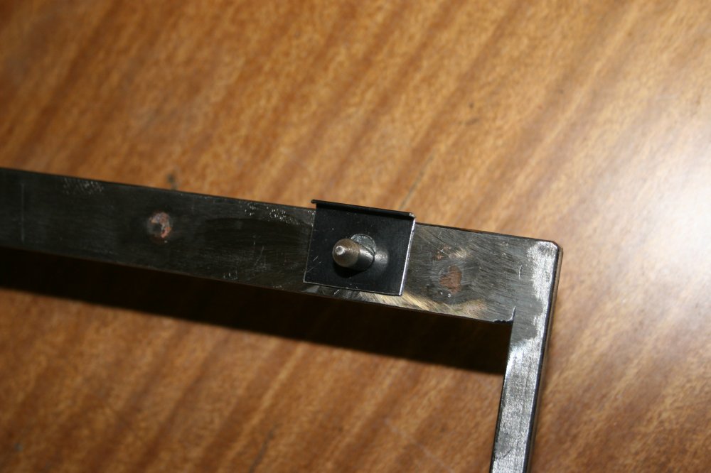
Next problem — each of the two frames will be attached to a side panel by four pins, with (hopefully) a clean fit to four holes in the panel. How to make sure the frames are interchangable, ie both have identical spacing of the pins?
|
|
|
|
|
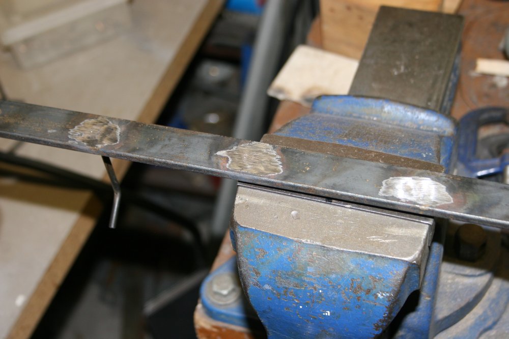
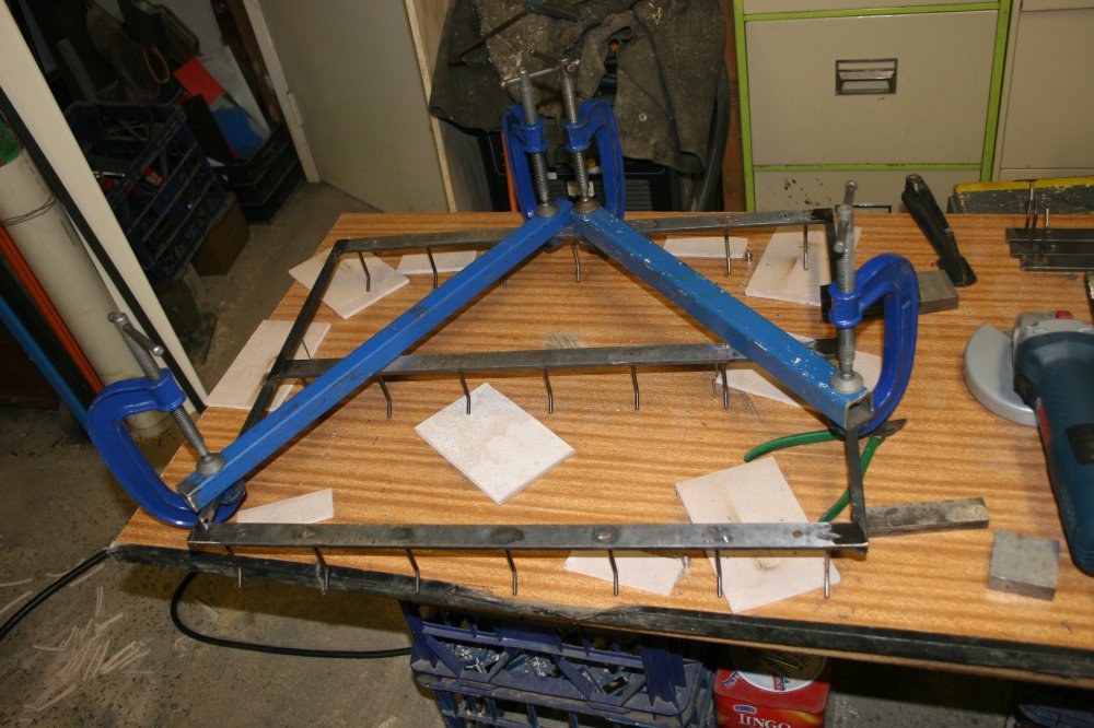
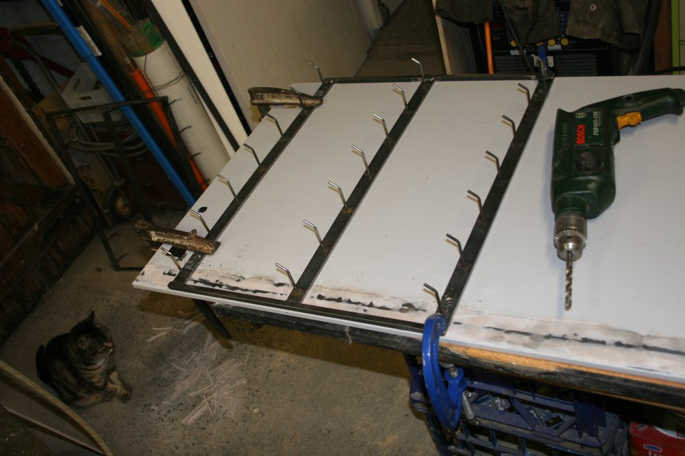
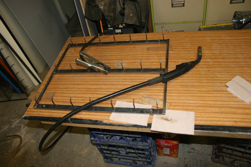
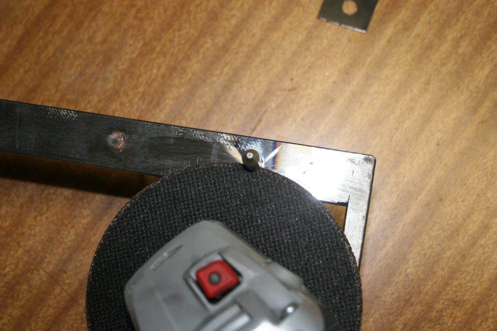
For this I dug out an old scrap piece of laminated chipboard from the junkshed. Lined up one of the frame pieces set, clamped it down on the board, and drilled holes into the wood using the holes in the metal frame as guides. Then pressed the metal pins into the holes. I'd already turned one end of each pin to a cone in the lathe. With the pins holding the frame pieces rigid to the board the frame pieces were then welded together. To weld the back sides of the joins, some diagonal bracing was clamped on to prevent any shifting of the pin geometry. One of the frames was then clamped to each of the rack side panels, and holes drilled in the panels using the frame holes as guides. Finally after all that, the steel pins could be welded into the frames.
|
|
|
|
|
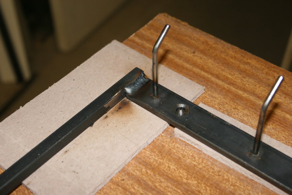
Then the final touch — cutting the 'drop-down' slots into the pins. The thin cutting disk in the grinder is just a little bit thicker than the sheet metal of the side panels. With the cutting disk lightly against the rear of the frame metal, slots were cut in the pins by eye to approximate a semicircle formed by the sheet metal hole edges moved up about half way through the pins. The small black metal tab in the pictures was an 'estimator' tool made to help judge when the slots were correct. In the last photo it shows how the frame pins sit in the side panel holes when fallen into position.
|
|
|
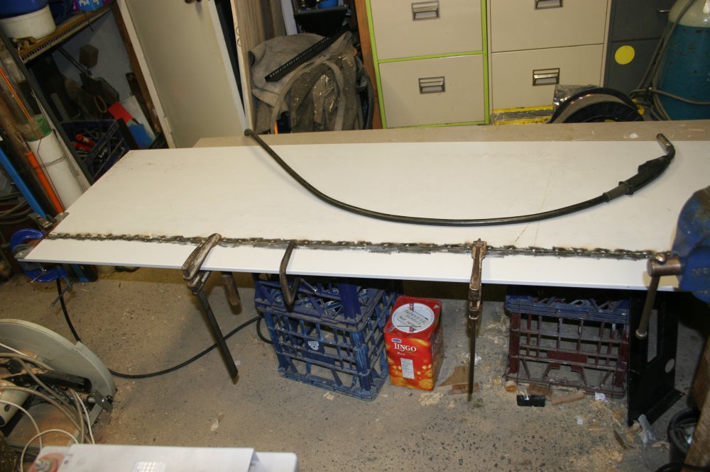
The frames fitted nicely, and are interchangable. At least one thing worked right in this project. The left side panel looks OK after painting. I couldn't resist putting a couple of aligator leads on a hook, even before taking the frames off again to paint them.
Here's how it turned out.