Back in 2017 one of my Melbourne dumpster finds was The Blue Thing. The parts I kept from that included a hotplate element, a temperature setpoint controler and a timer.
A few weeks ago someone gave me an iPad 'mini 3'. This model was released in Oct 2014, so it's old now. This one is locked and disabled, so useless as it stands. But the mini 3 is a nice size for general use as a bluetooth-linked display. For instrumentation, camera driving, etc. If only this nice-looking device was not typical closed-box Apple rubbish. Can anything be done about that?
This came at a time when I was getting impatient with a few other projects that had been taking a while. Among them a building extension (going well), car repairs (not going well, due to involvement of a dodgy mechanic taking months to do an engine recondition), the big lathe install (waiting on building works completion), the vacuum chamber build (waiting on the lathe), and several others. Most will be written up, but only once they are finished.
So a quick non-blocking side project appealed. 'Quick' ha ha.
Googling for 'iPad jail break' led to articles on altering jumpers on the CPU PCB, and thence to videos on how to remove the glass from iPads to get to the PCB. Same process as with most cell phones incidentally. As you'd expect the glass is glued on, but can be removed intact by heating till the glue softens, then using suction pads to apply the required pulling force. There are many, many youtube how-to videos on this process. And a near infinite number of online advertisements for heating and screen-separation tools — almost all from China. Some ultra-simple ones quite cheap, but the more fancy models going up into the thousands of dollars.
One thing I noticed was that all the hotplates are just that. So you have to take the device off the hotplate to pull on the device's glass and rear at the same time.
Hmm... In the background I've been thinking of a project (partly related to 3D-printing), which involves a large heated vacuum hold-down bed. Which will be a major design effort due to the size. Probably a good idea to try a smaller and easier concept test first. And I have the hotplate bits from the Blue Thing.
OK, sounds like a fun diversion. Completely sealed, 'no user serviceable parts inside' devices like iPads stand as a challenge anyway. I've always wanted to be able to thumb my nose at this particular variety of planned obsolescence.
 |
 |
 |
 |
 |
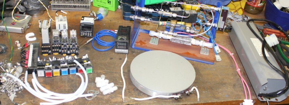
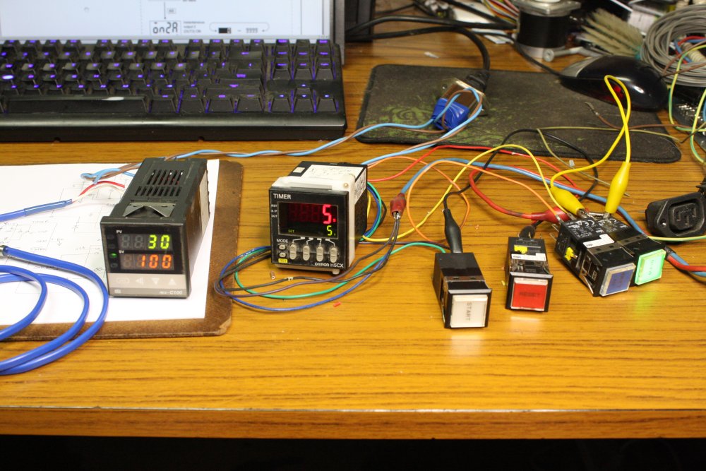
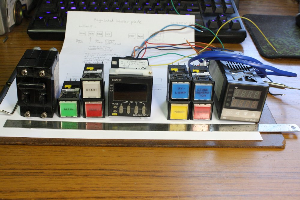
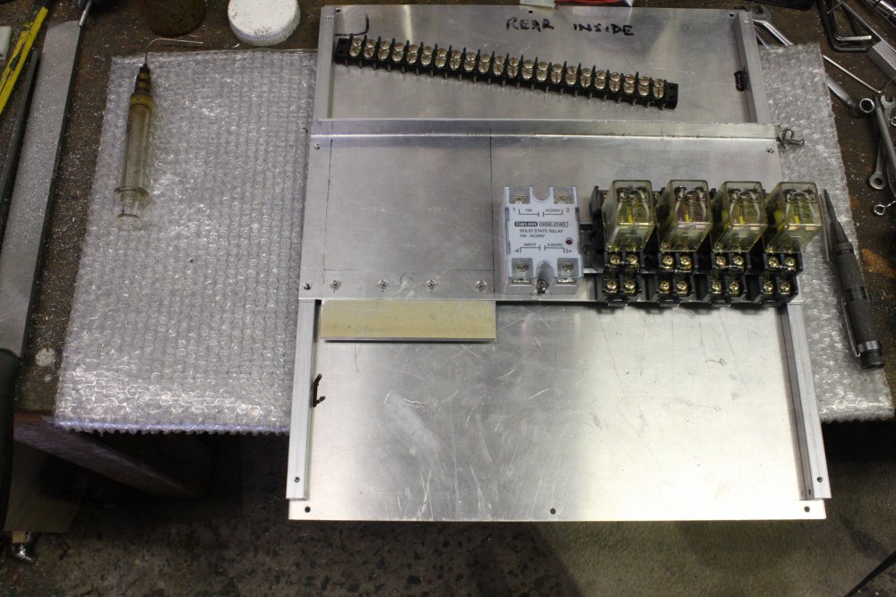
1. Manuals for the set point controler and timer found and downloaded, here checking both units work. Also checking the buttons from the Blue Thing. They turn out to contain LED modules that include bridge rectifier and current limit, so the lights work on both AC and DC 24V. Good. I drew out enough of the system circuitry, that I knew what the buttons would do. A bit more than simple on/off, since I want the timer to be optional in use. Ie it only becomes involved if you want it to. Which means there is a very simple state machine required. One that can be done with a couple of relays. Using a microcontroller in this would be overkill.
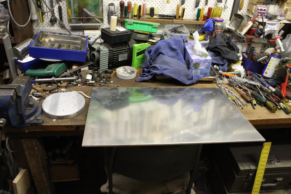
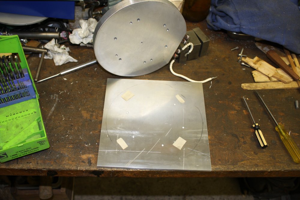
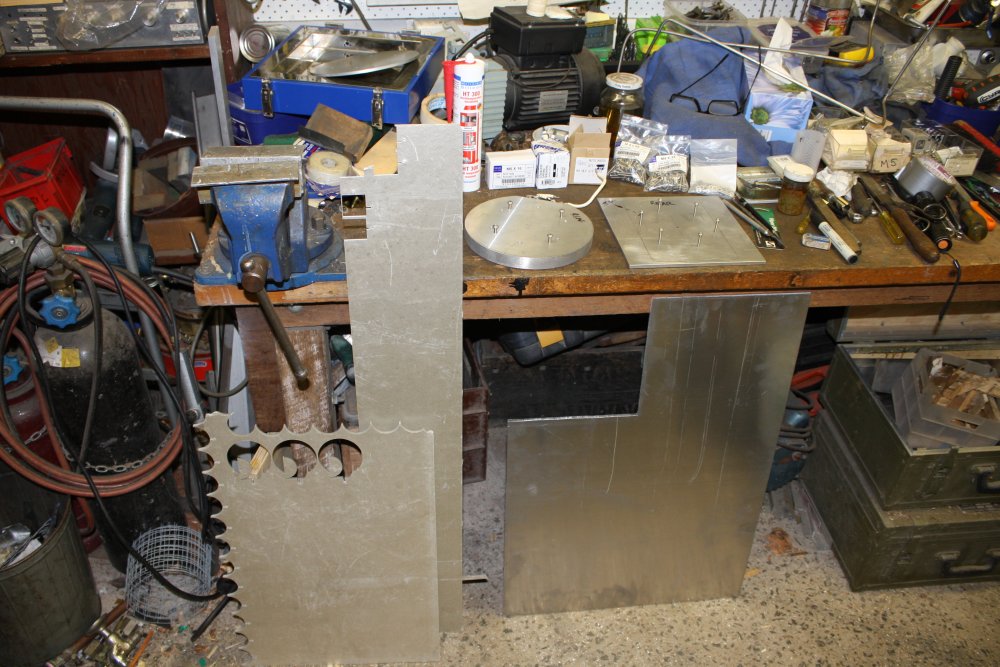
2. The original hotplate surface is a disk of 5mm thick aluminium, screwed on top of the heater disk. It's not big enough for the iPad. I need a larger hot surface, both square and thicker. So I bought an offcut of 6mm thick aluminium plate.
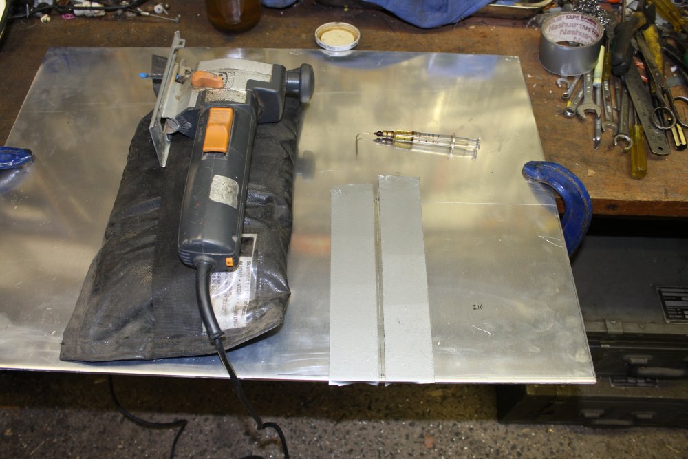
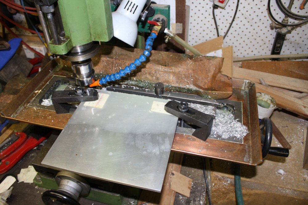
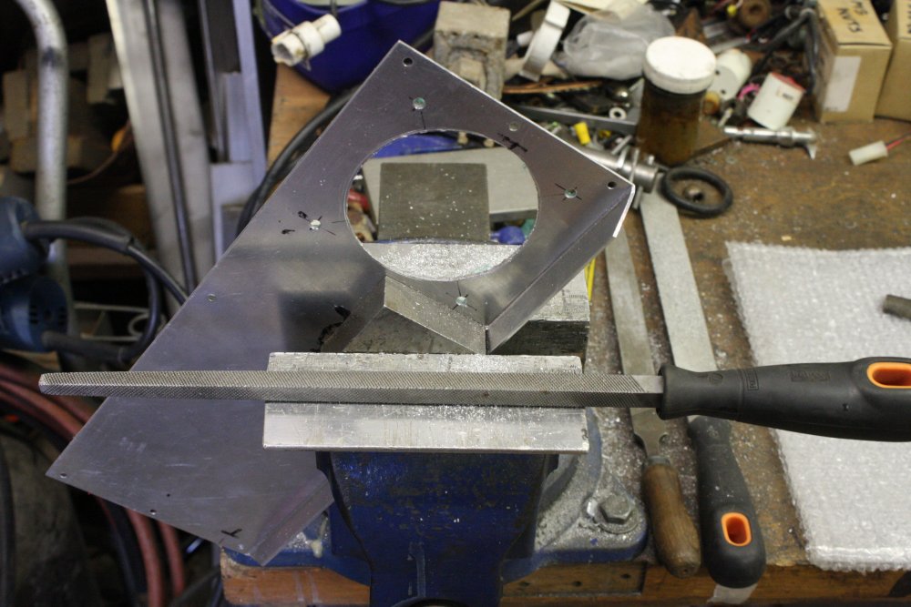
3. Cutting out the square. Jigsaws leave a rough edge, so I'll cut just outside the line and clean it up later. The syringe contains kerosene, to run along the cut to prevent blade clogging. The tape is to protect the sheet surface from being scratched by vibrating jigsaw foot rubbing metal sawdust into it. The black bag contains metal punchings, is very heavy and limp, and makes a good sound damper.
4. Making the edges neat in the mill. Final size is 215mm square.
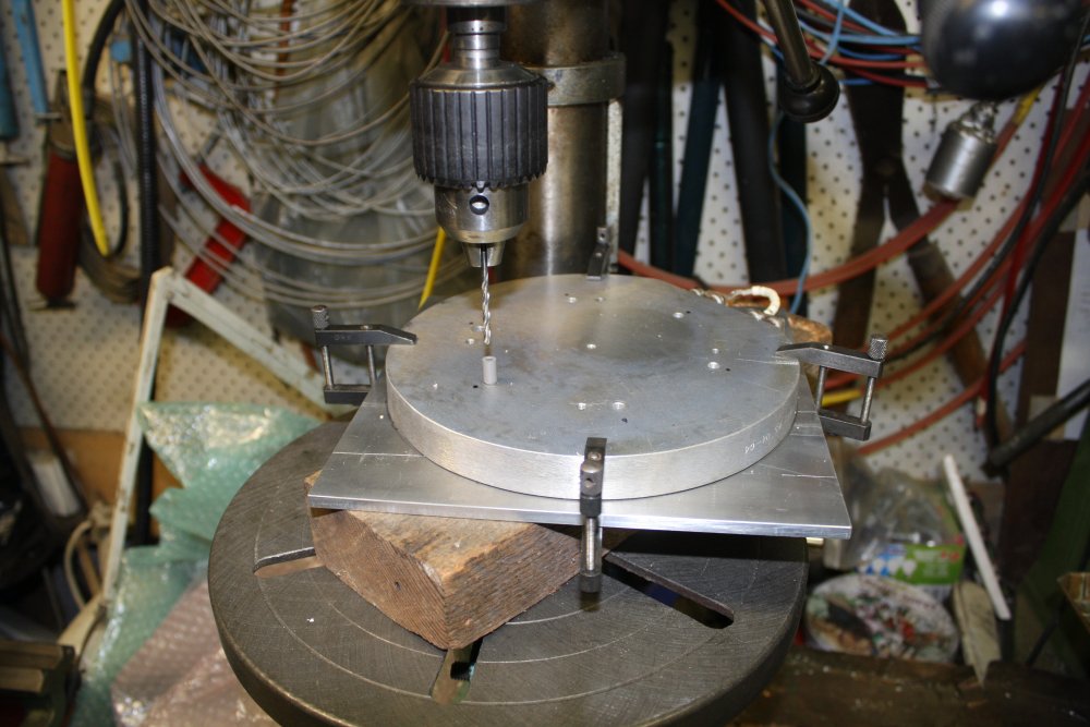
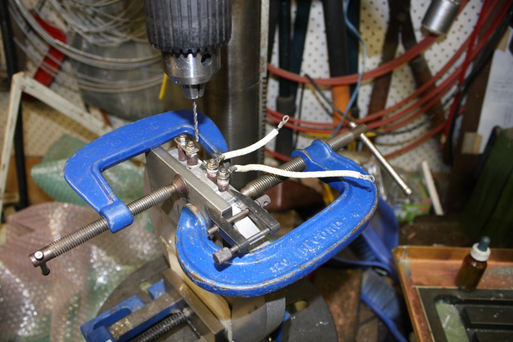
5. The heater disk and top plate are held together by six screws. The tapped holes for these in the top plate must be shallow blind holes, tapped right to the hole bottom. They also must be exactly centered on the existing holes in the heater. So here I'm transfer drilling them, using a centering insert. Also I've reground the drill bit cutting end, to be very nearly flat. With only 6mm of plate thickness every half millimeter of thread counts. I'd very carefully set the drill press end stop to leave just 1mm of metal between the hole bottom and the far surface of the plate.
 |
 |
 |
 |
1. I had also checked the relative positioning of the parts, in the existing housing. Couldn't use clamps there (no space) so had temporarily fixed the parts together with double sided tape.
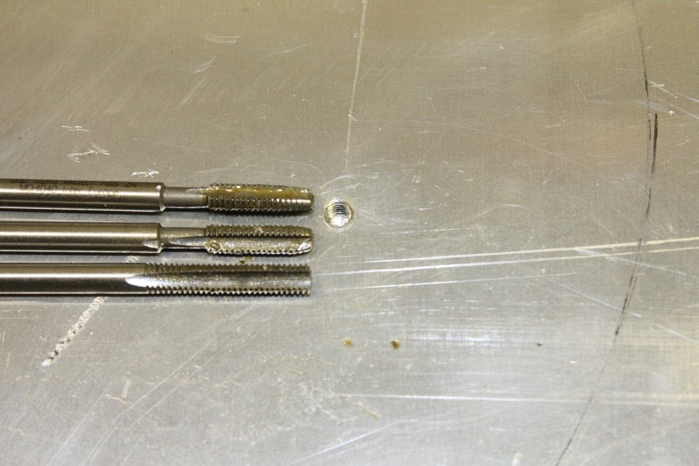
2. Tapping the blind holes, M4 thread. Standard taper (starting) tap, then standard intermediate, but for the bottoming tap I ground the end off a normal tap. Giving thread right to the bottom of the hole.
3. Between the hot parts and the stainless steel enclosure, I wanted some sort of standoff at least 5mm and with reasonably low thermal conductivity. The temperature for removing iPad screens is around 100° C, but the plate and controler can go up 400° C. I'd like to be able to reach 300° C at least. So the spacers need to survive such temperatures. Nylon is out.
What to use then? I found a source of silicone-bonded mica sheet. Bought two offcut sheets, one 5mm thick, one 3mm.
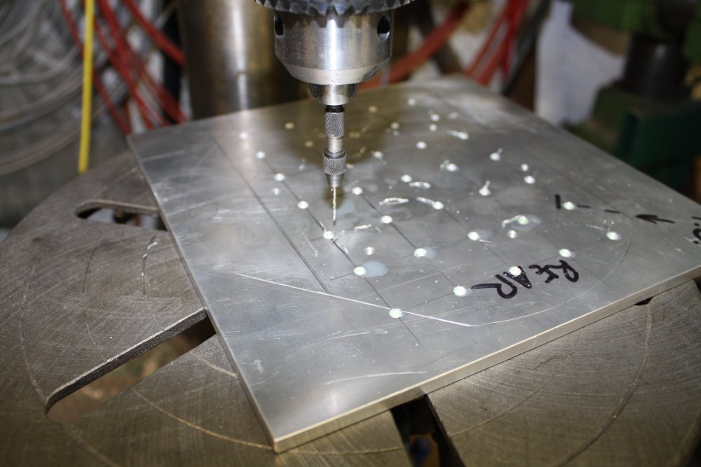
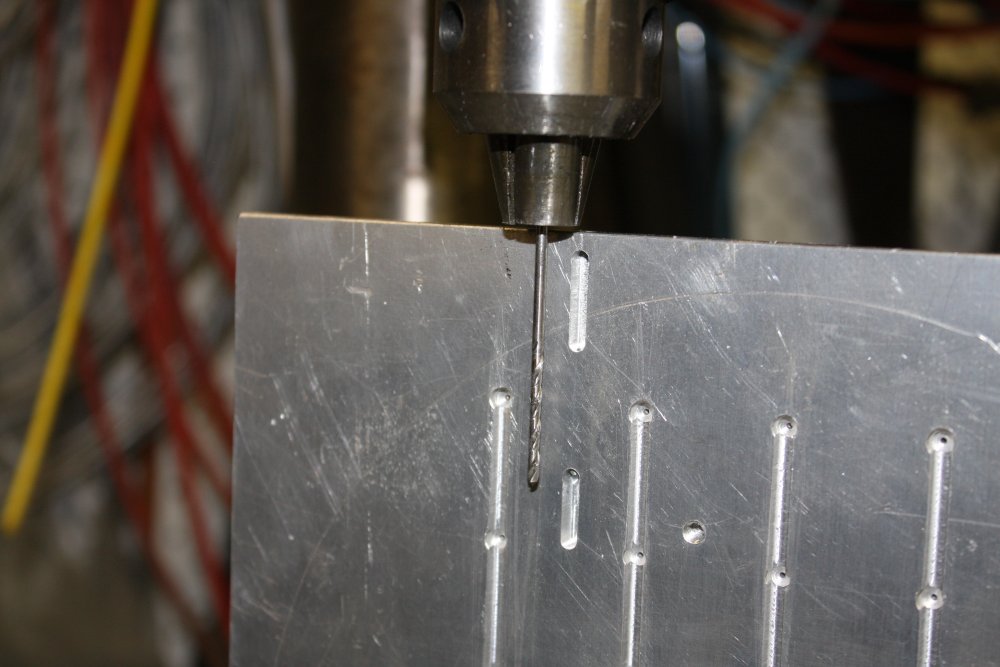
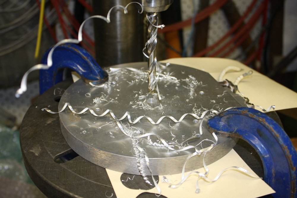
4. Drilling the 1mm dia air holes in the surface plate. Drilled a 3mm 'junction' hole half way through the plate from the bottom side, then 1mm the rest of the way.
 |
 |
 |
 |
 |
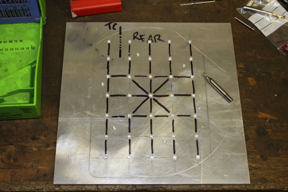
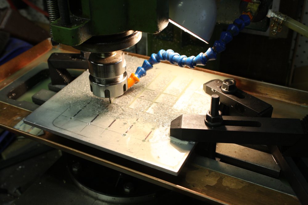
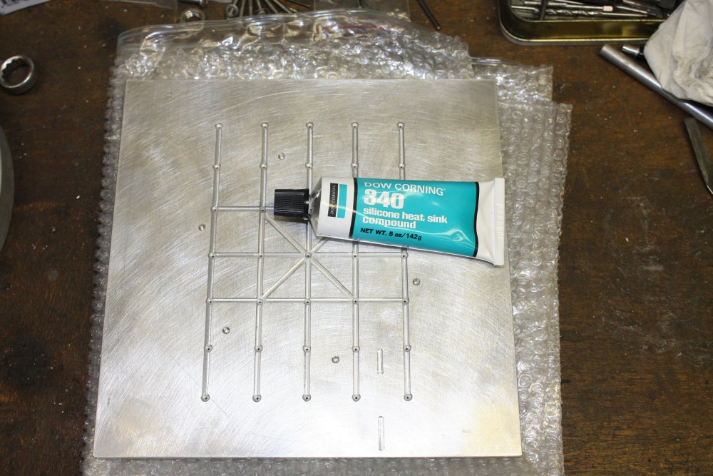
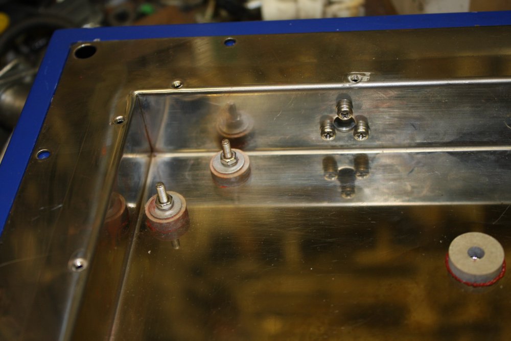
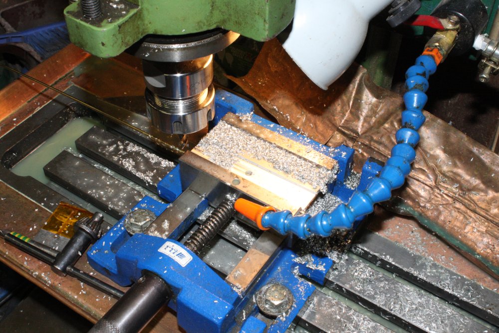
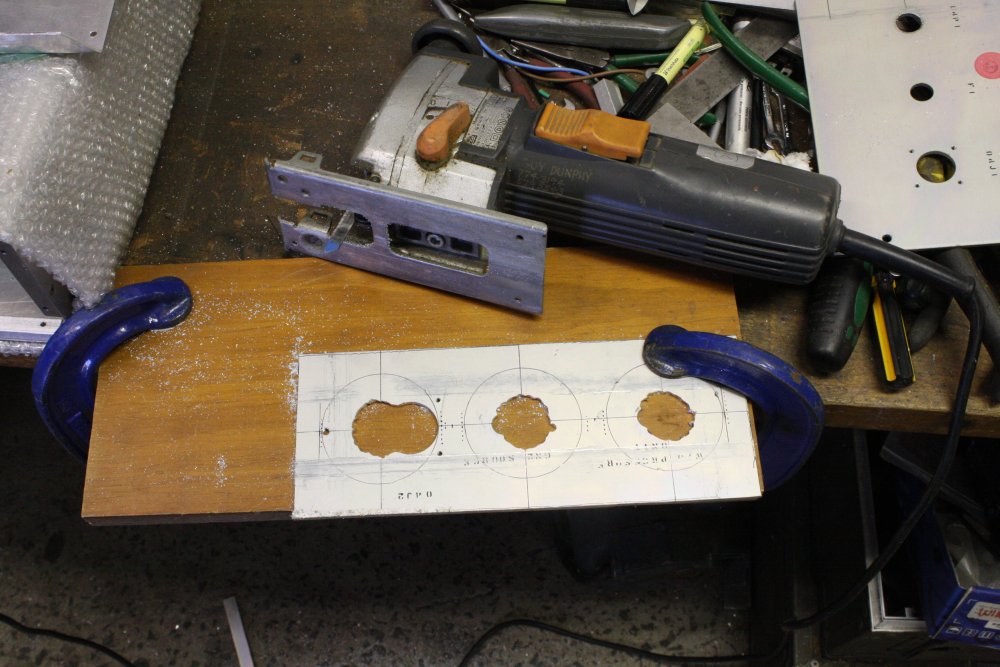
1. The vacuum connetion will be to the center of the holes array, with a mesh of channels between the holes. Here the channel pattern is marked roughly by hand. The 'TC' line is where a hole will be drilled for the fine thermocouple probe.
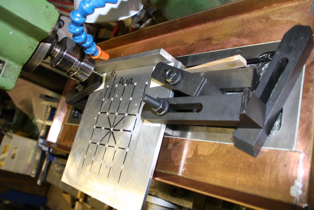
2. Lining up and clamping for the channel milling.
3. Milling, by eye. The channels just have to intercept the junction holes, otherwise accuracy is not important.
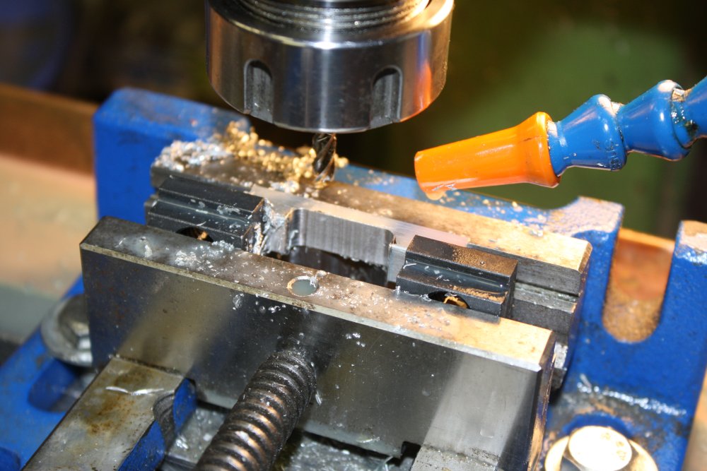
4. The hole for the thermocouple probe has to be drilled from the plate edge. That's how long the drill bit is, but I wanted the probe further in. Hence the milled extension slot. Also the probe can't project out the side of the plate, so has to curve in via another milled slot. The inner slot will be filled with thermal conductive paste.
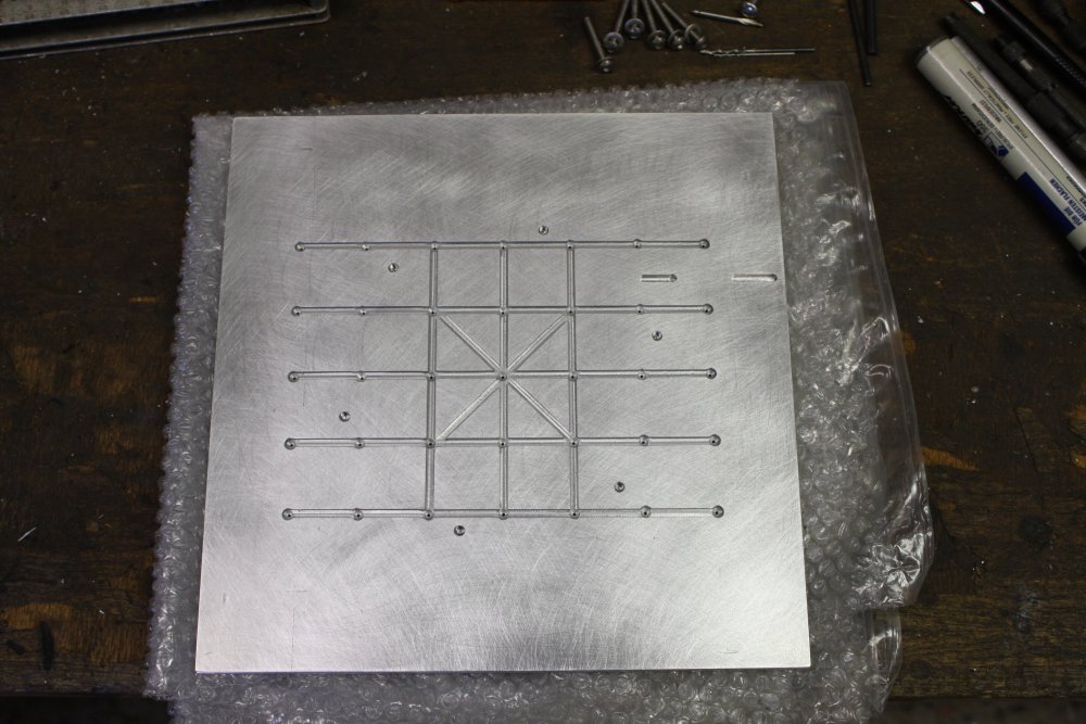
5. Machining of the plate completed.
 |
 |
 |
 |
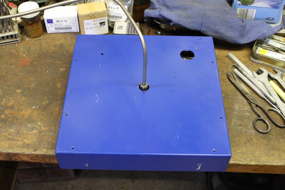
1 - 4. A minor annoyance was that the heater disk has a flat edge, where the elements come out. One of my vaccum hold-down holes in the top plate unavoidably coincided with that heater flat, so the suction channel was open to air there. I had to add a small extension to the heater plate to cover the vacuum channel.
This involved drilling holes into the cast aluminium body of the heater plate, trying to avoid drilling into the heater elements embedded in the casting. It's pretty clear where the elements should be located inside, but there's no way to be 100% certain. So this and other drillings into the heater were fingers crossed and a bit tense. Fortunately all holes missed the elements.
Incidentally here you can see the original
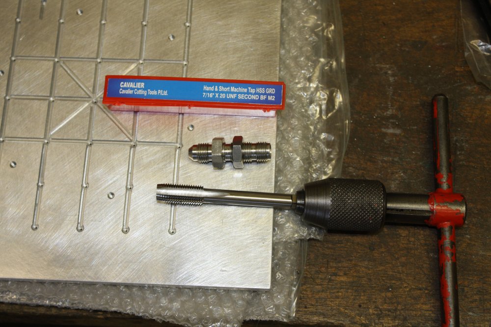
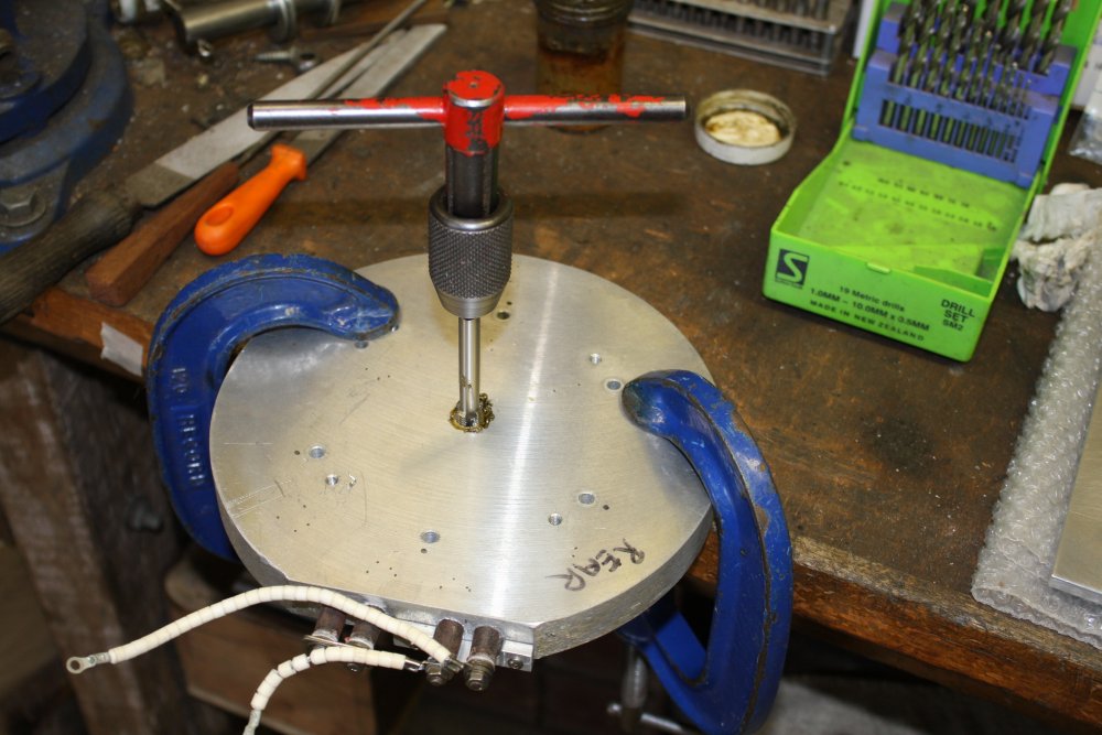
1. For the vacuum plumbing attachment point I'd found a stainless steel fitting and some tubing that mated with it. Problem — I didn't have a tap that matched the fitting thread. So, a quick trip my local 'everything to do with fasteners' supplier to buy this tap.
A visit that should have been trivial, but turned into one of those facepalm chain of events. Wish I could do that one over again and get it right. Sigh.
2. The hole for the fitting. Another tense 'please don't hit the elements' moment.
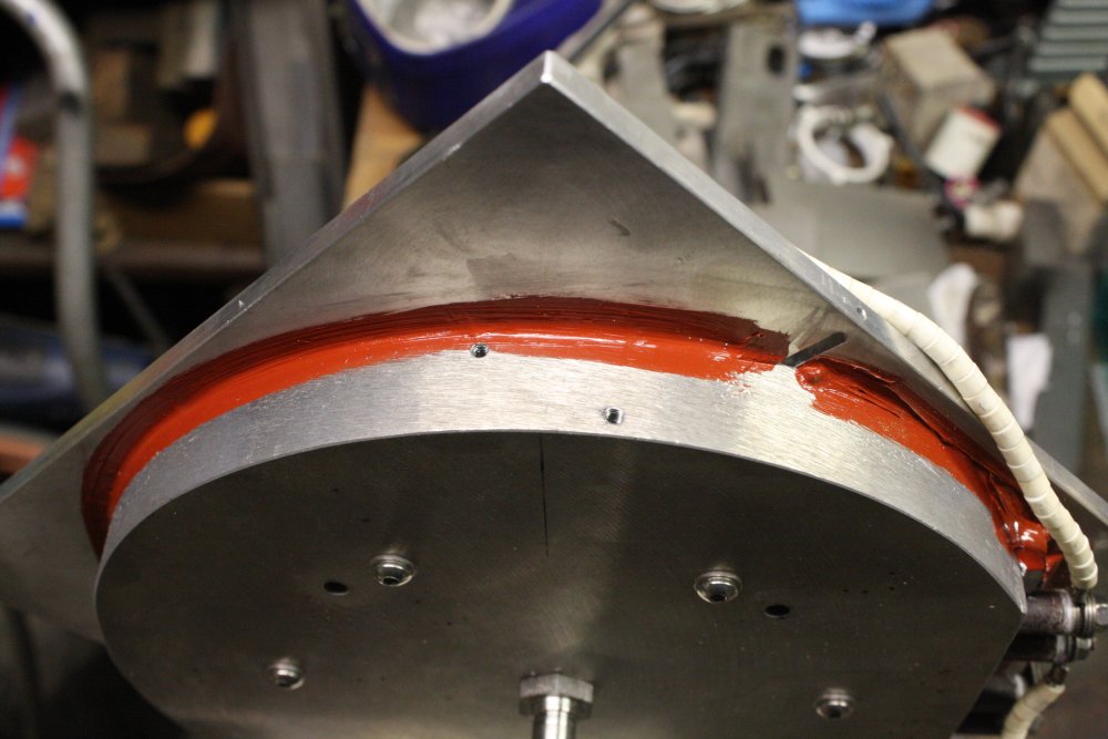
1, 2. Applying heat conductive paste between the heater and top plate. The most important thing being to avoid excess since that would squeeze into the vacuum channels and block them. The much larger vaccum hold-down bed I'm thinking of constructing won't have this problem, due to a qute different structure.
Back to that mica sheet. It's very rigid tough stuff except in one direction. It delaminates quite easily. Which makes cutting it a problem. The supplier has a water jet cutting machine, hence the nice clean cut profiles on my offcuts. I need to cut some round washers from this stuff but don't have a water jet cutter. So how?
It's soft enough for ordinary cutting tools to work. It can be cut roughly with a hacksaw or angle grinder, but these damage the material for a few mm on either side of the cut.
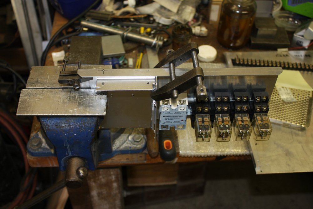
1. The answer is to keep the material under strong pressure, right up to the cut edge. So long as the material isn't allowed to delaminate it's fine. Here I'm drilling holes using a clamping jig I'd made for something else recently. It works very nicely.
1. At the place that supplied the mica sheet (Associated Gaskets), I also bought a tube of high temperature silastic. It's good up to 300° C. Used here to air seal around the disk edge.
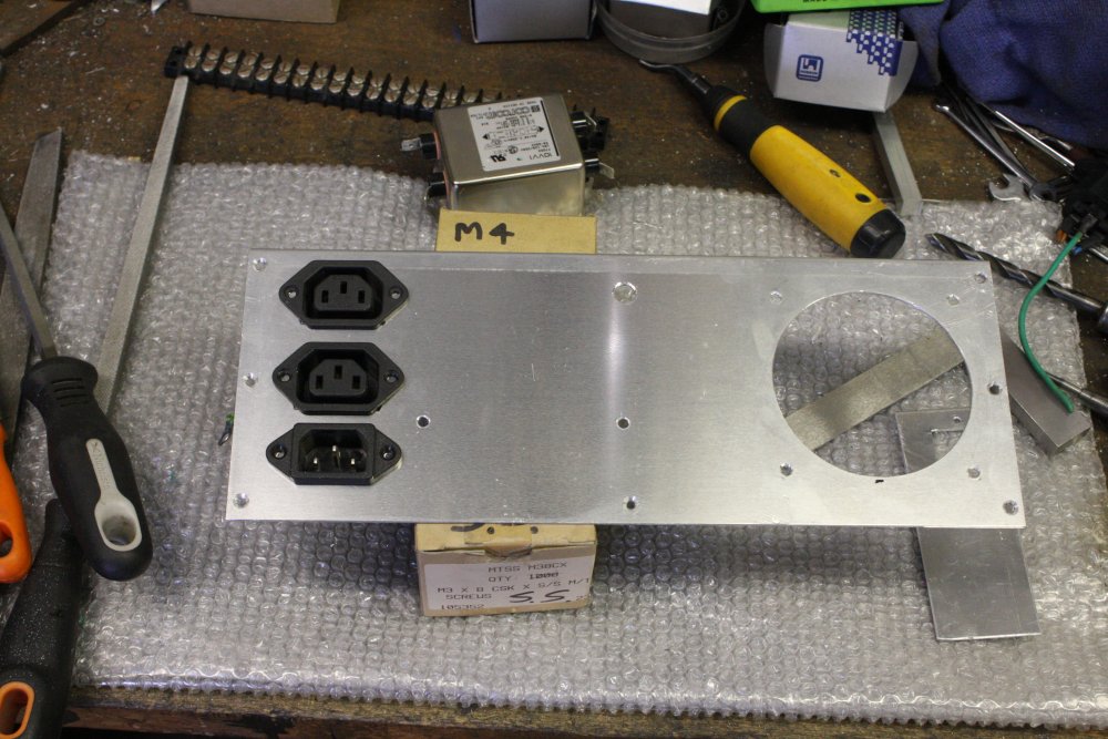
Now for the chassis. Heh. Virtually all the commercial units I saw online are plain rectangular boxes. Which means front controls are on a vertical plane, close to the benchtop. Ergonomically quite a pain, pushing small buttons on the controller units. I'd rather mine was nicer, and don't care about the slight extra consruction effort.
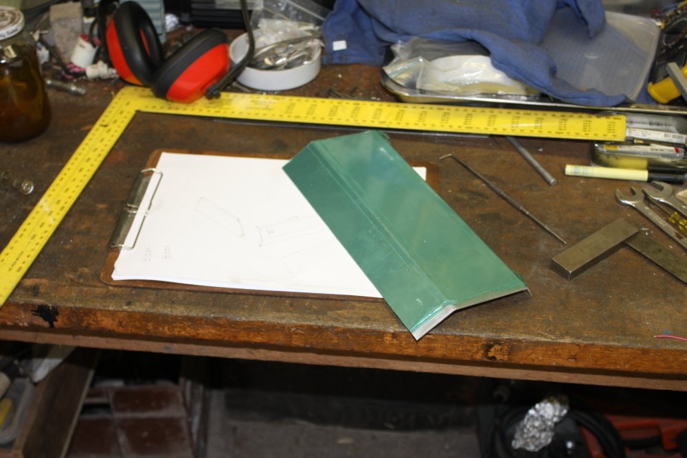
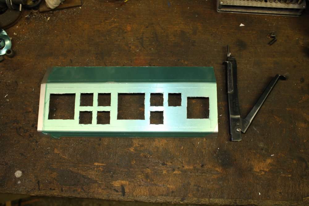
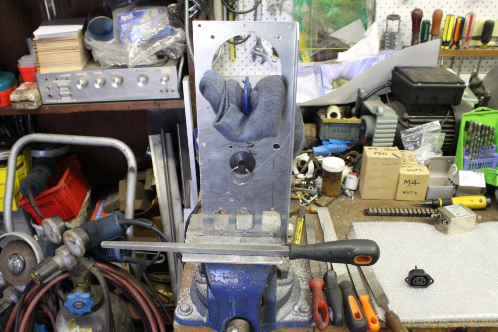
1. The front panel. The controls will be on a 45° slanted surface. I folded this first, and will cut side panels to match the shape. I'm not very good at making folded sheet metal end up exactly the shape I want, to fine tolerances. So when I do want a close fit, I minimize the number of metal folds. Sizes came from the rough layout of controls I'd done before.
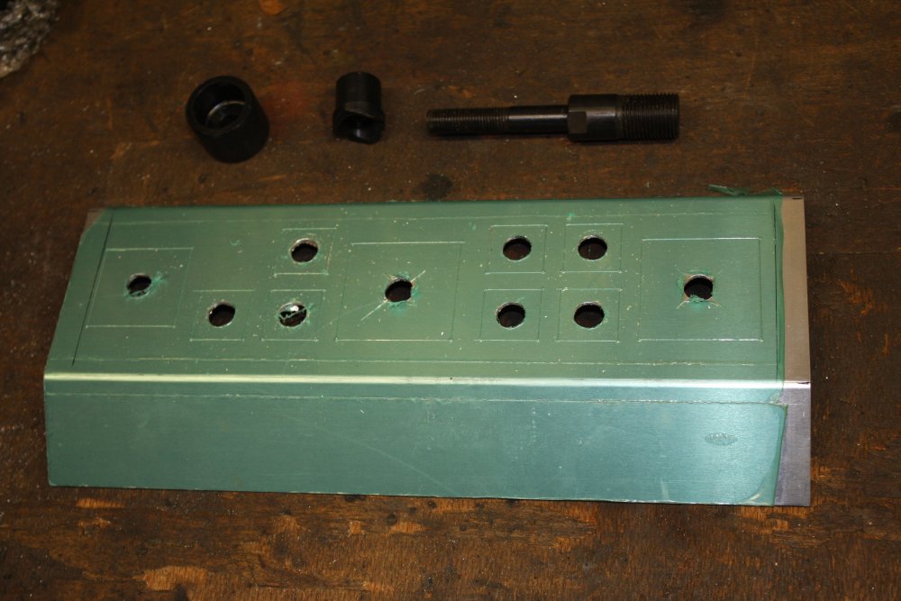
1. Lacking a big CNC sheet metal punch, square holes are a pain. I have a hand operated hydraulic hole punch, but the dies are all for round holes. They help though. First step is to drill center holes for the hydraulic punch draw rod.
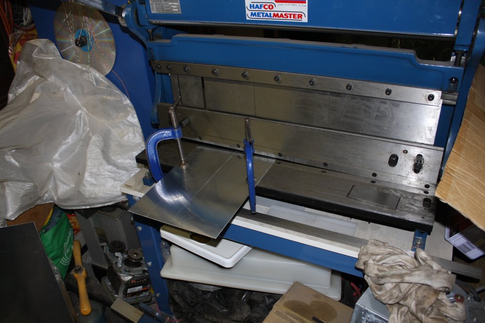
1. It'a a hard battle, but my guilotine and folder machine hasn't yet been buried by creeping junk accumulation. Here cutting the side panels.
Attaching the hot plate assembly to the chassis. An issue is to allow its removal without access to the join line. Since the inside of the hotplate unit can't be accessed (thermal insulation, etc) and neither can the interior of the chassis unless the bottom plate is removed. I don't want that to be the only way.
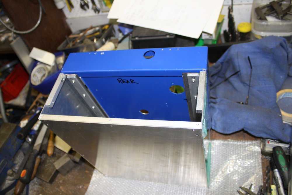
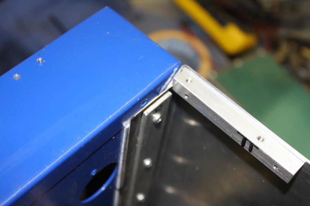
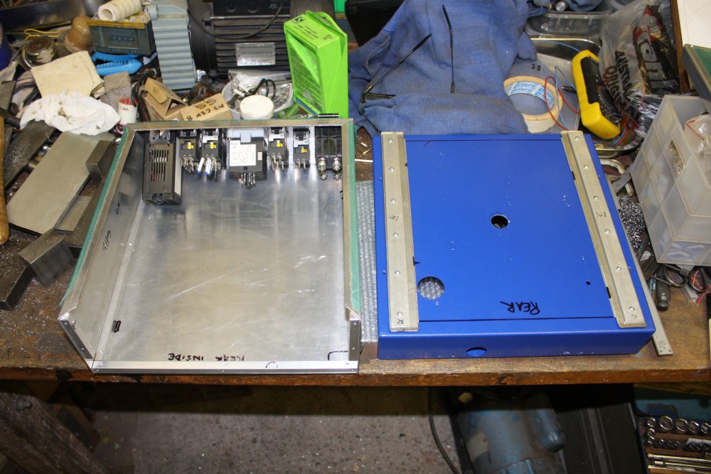
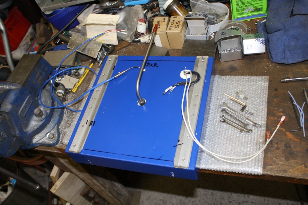
And so, a slide-in system, that only required the rear panel be removed to free the hotplate.
1 - 3. Aluminium against aluminium doesn't slide well, and tends to spall and jam. So the hotplate has slides of thin stainless steel, backed up with thicker aluminium.
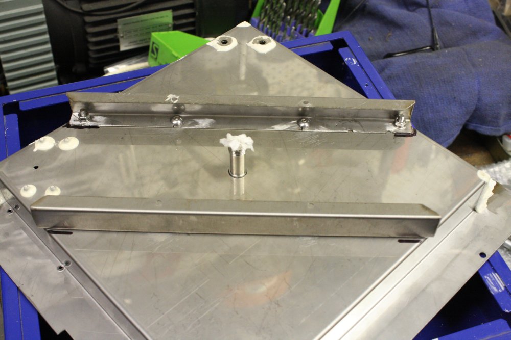
1. The old hotplate wasn't designed to resist any 'user-applied-forces', so had no bracing on the enclosure sheet metal. With my hotplate mounted, it would flex visibly under force. So I added these struts. Flexure problem fixed.
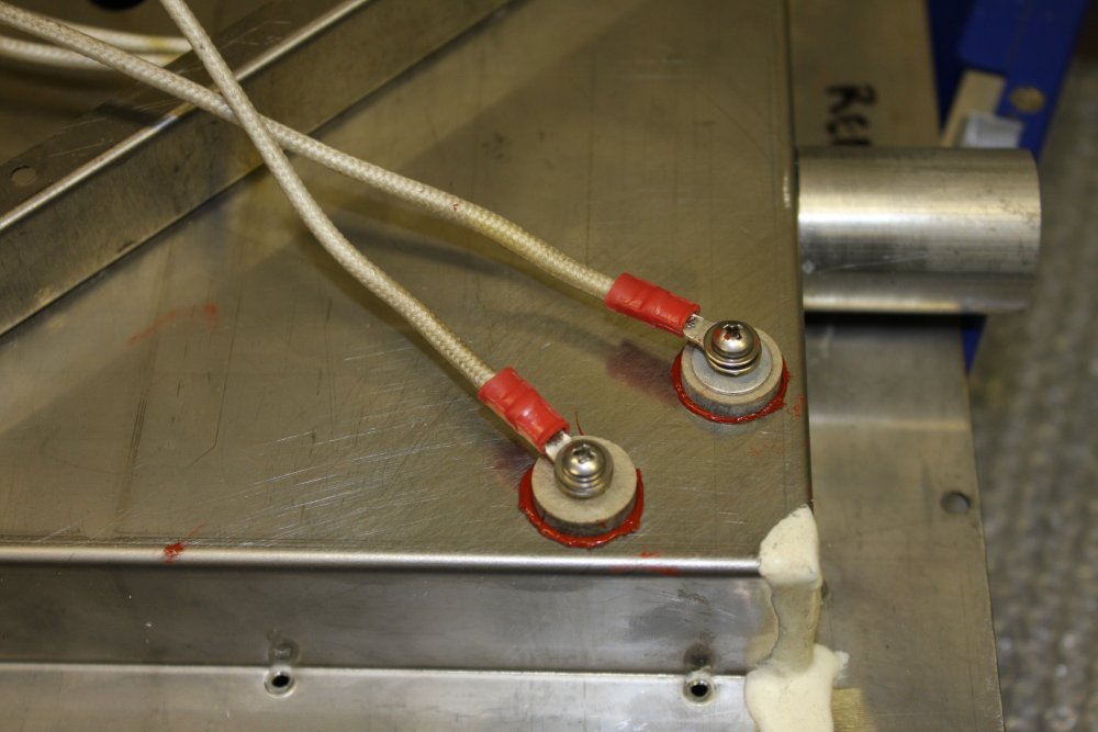
1. Power wiring for the heater. Originally there were thin ceramic posts here, with tiny 2mm screws. I wanted to use M3 screws so made some more mica washers (with lips.) This is the result. Spot the missing washer! I'd just screwed it together quickly last thing in the evening, to let the silastic glue set. I noticed the missing washer next day and added it. The mica washers are not part of the tensioning for lugs at either end.
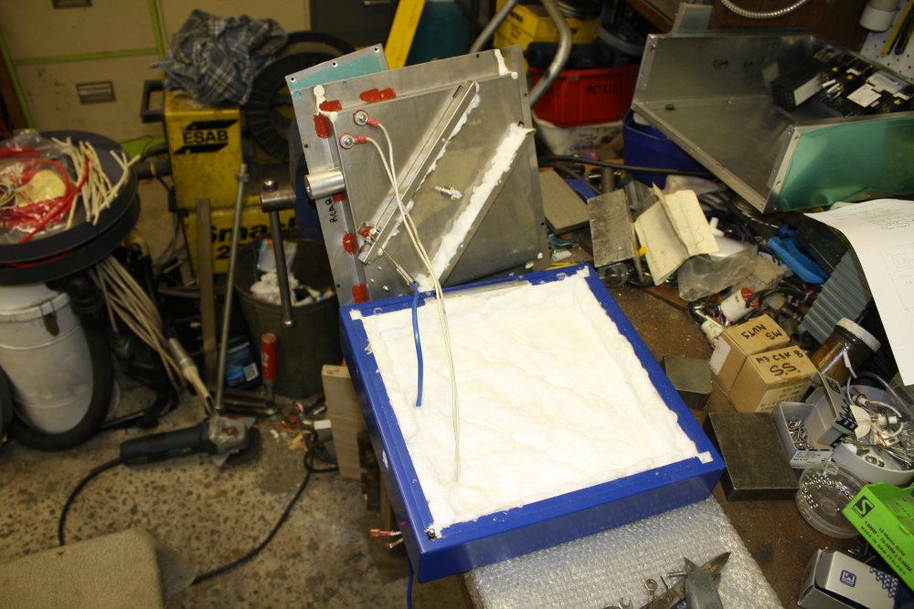
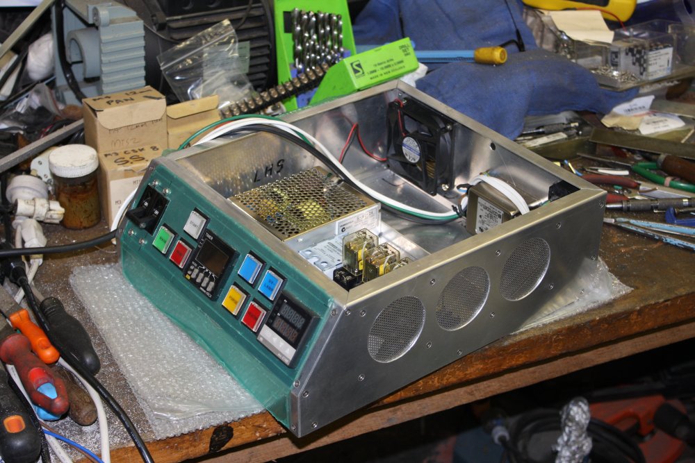
1, 2. Assembled into the outer casing, with the refractory glass wool insulation.
1. Well, that bit of metal was almost perfect. But a little too narrow to mount the +24V power supply. So here making a an extension piece.
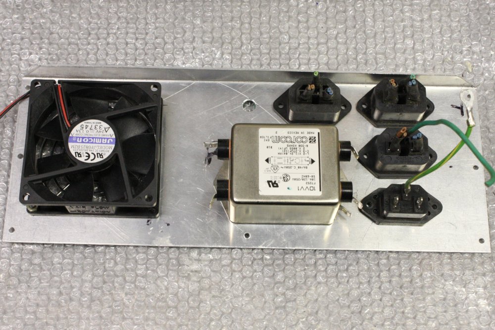
1. For one thing, almost all the wiring was ridiculously over-rated. Even if they did want to use one wiring gauge for everything, it could have been much smaller than this. The switch contacts are rated for 2A max, but these black wires are 14AWG, 2.08 sq mm. Rated for 32 Amps in chassis wiring. Furthermore this thick wire is seriously unsuitable for connecting to the small tabs of things like these switches. I've no idea what they were thinking.
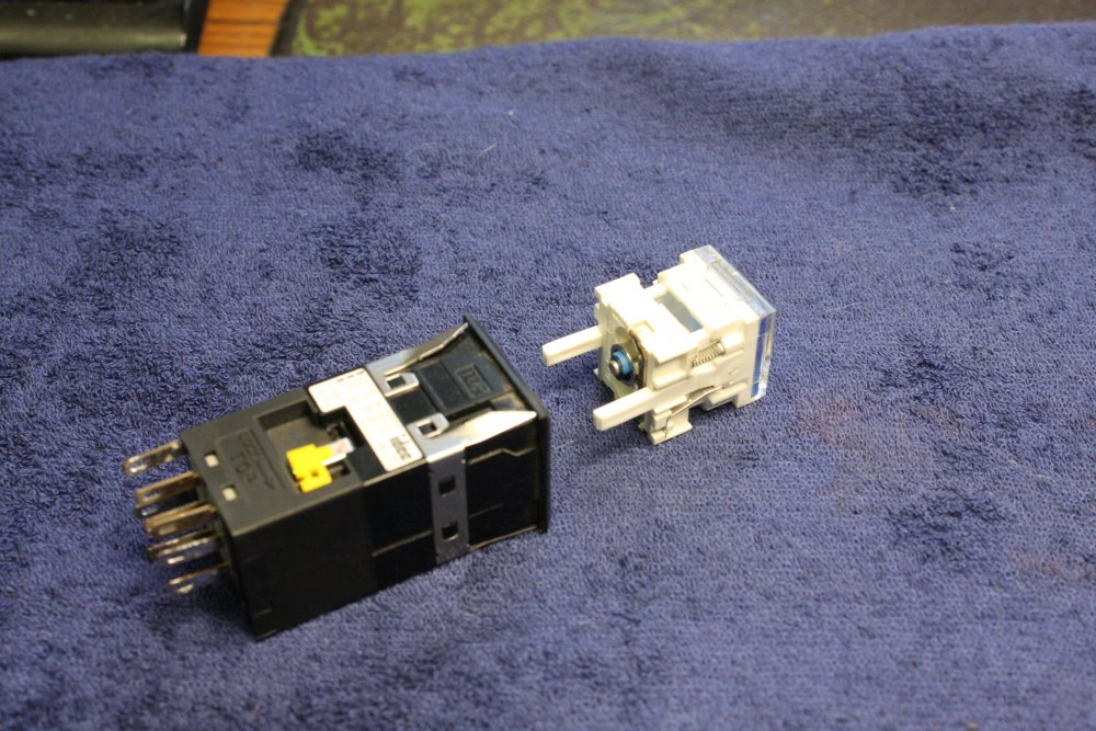
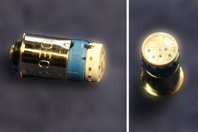
1 - 3. The button comes apart from the front, to allow bulb replacement and custom labelling. With the bulb closeup shots, I goofed a bit with the photoshop combine and background blur. Spot the bad outline select.
I need to relabel a few of the switches. Wonder if the very old Letraset sheets I have are still good?
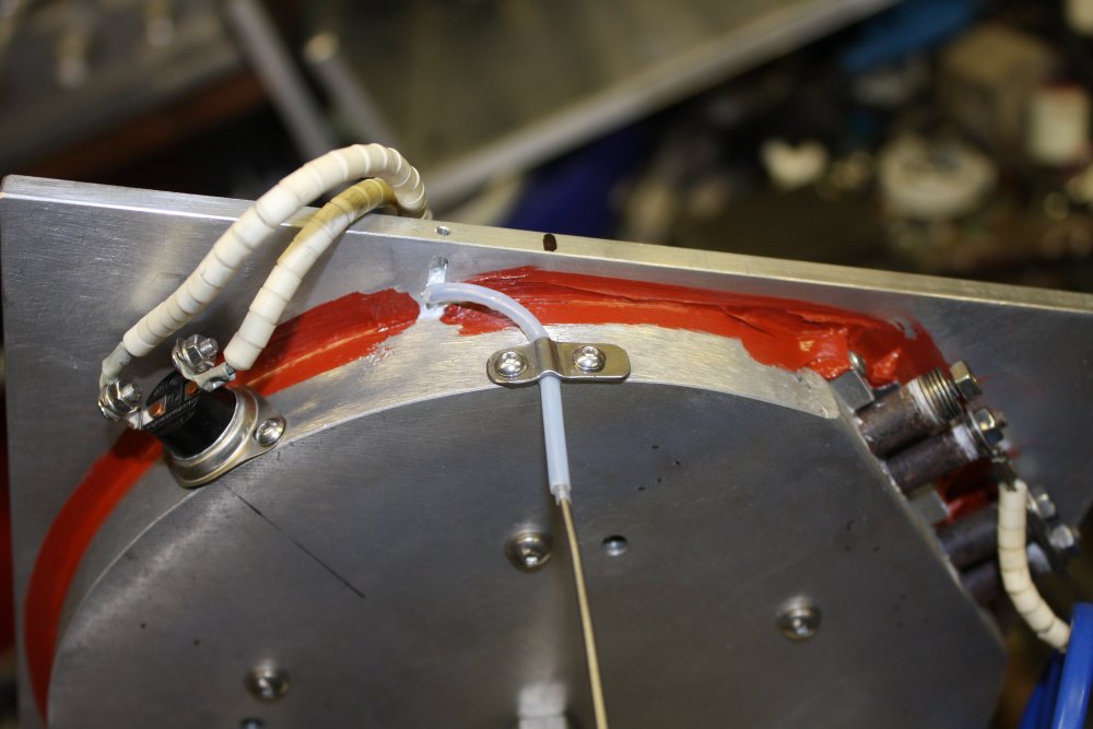
1. A slight adjustment to the vacuum tubing exit point.
1, 2. More hole perimeter drilling and filing.
The circuit tray needs a terminal strip too. I have lots of assorted ones, but the Blue Thing had a really nice one I'd prefer to use. If I could find where I put it... urrgh.
But I don't have much of that mesh, and it's hard to get. So at this point I had a rummage in the scrap metal pile.
1. Found this. A stainless steel grill from the bottom of an old dish washer, that I'd found as street-toss, and stripped by the side of the road. I like this better than the woven wire mesh, since it will sit flatter. Here meauring up the vent size, using the large hydraulic hole punch die as a layout puppet.
1. Well, I can cut the outline as intended. In fact it's easier than normal soft aluminium since this hard alloy does not clog the blade. No need for kerosene as cutting fluid.
Still can't find that terminal block. Somehow it never made it to the crate of assorted terminal blocks.
Anyway, I won't be doing that.
3, 4. Tapping and test fit.
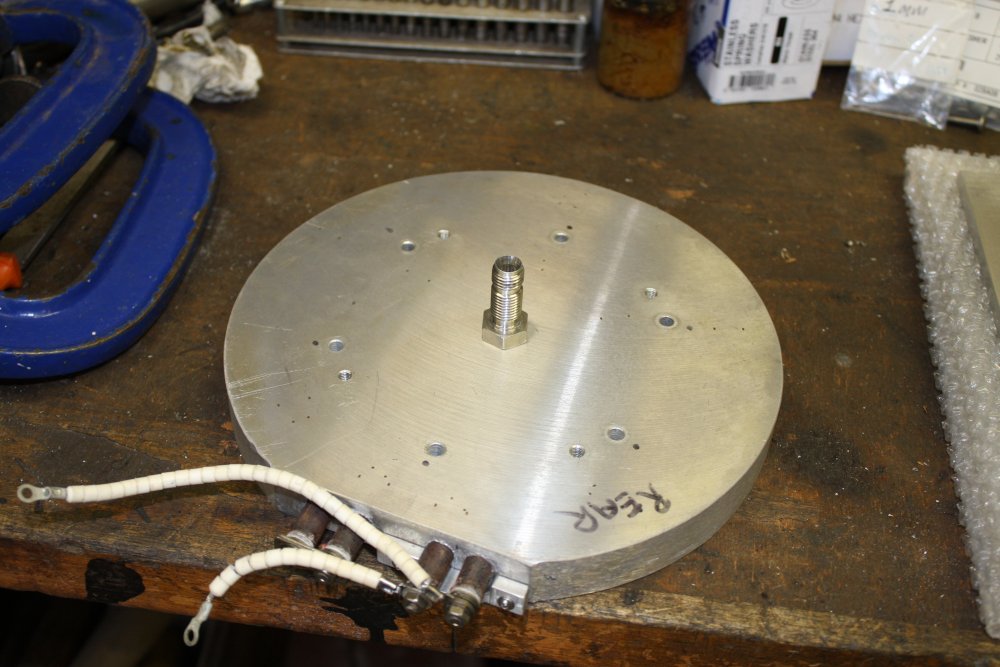
5. Decided to remove the superfluous bit of thread on the body. I also drilled out the center hole a bit larger. All to reduce the metal cross section and thus the heat conductance away from the hotplate via this metal. Which would be pointless if there was a continuous flow of heated air, but normally with vacuum applied and the target device sealed to the plate, there shouldn't be much if any airflow.
3. The six shallow-hole mounting screws are not strong enough to really squeeze the two surfaces together, so some G-Clamps.
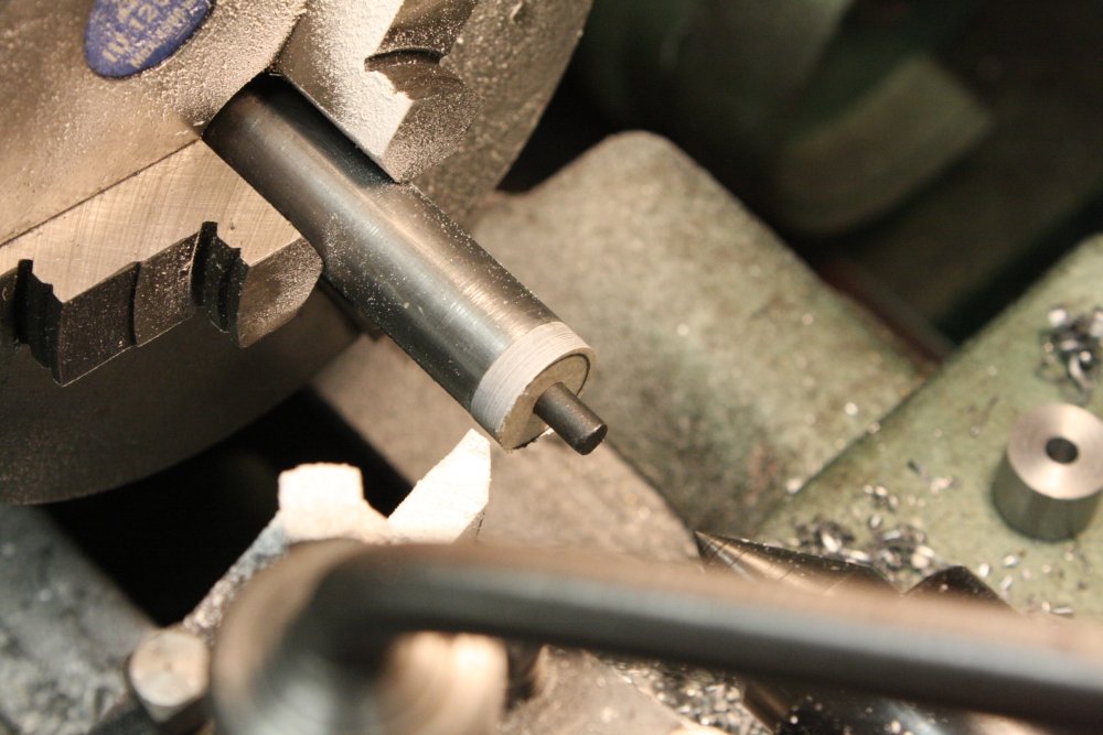
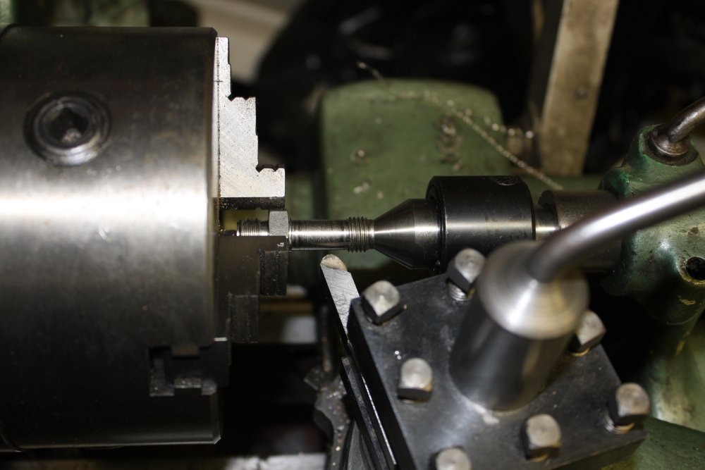
2, 3. Another quick jig made for machining the outside of the washer. The live center is applying a lot of force to the small part of the jig, keeping the material under compression. It cuts very nicely in the lathe.
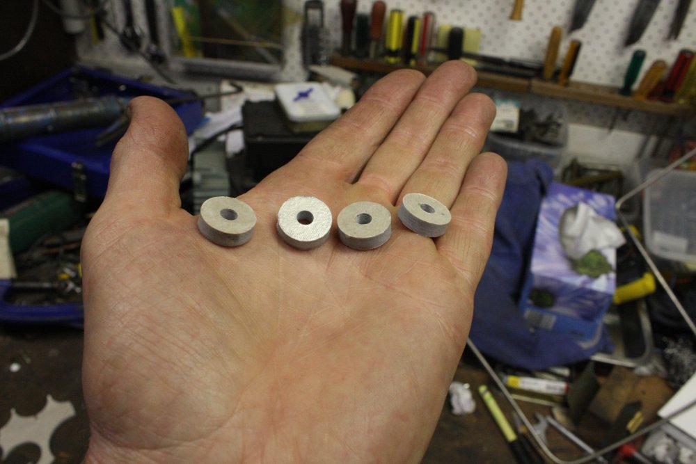
4. The resulting washers.
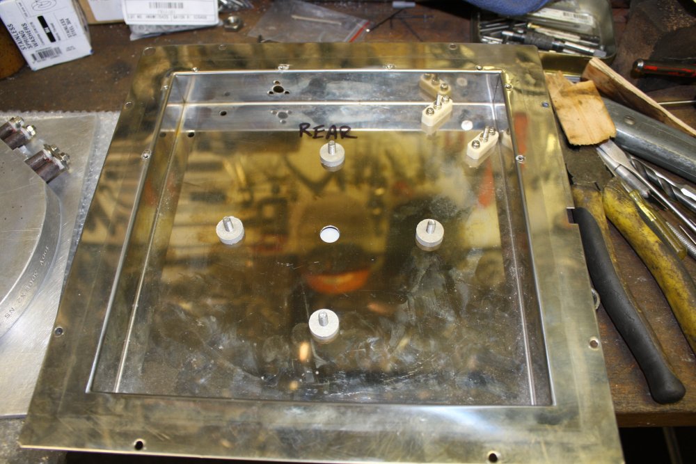
5. In place, later to be glued as well.
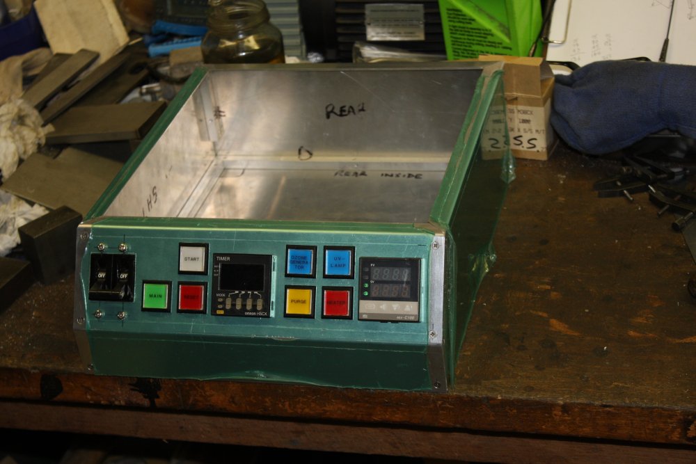
2. Working out the controls placement.
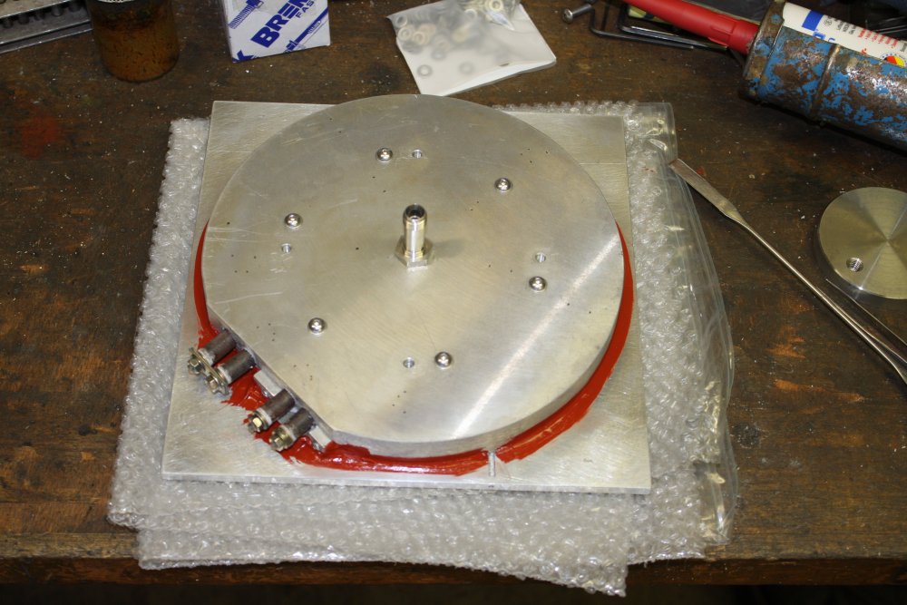
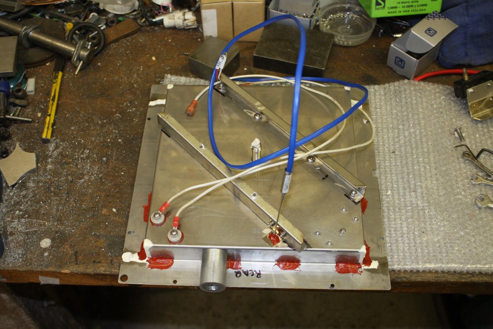
3. Trial assembly with the vacuum pipe. No insulation yet.
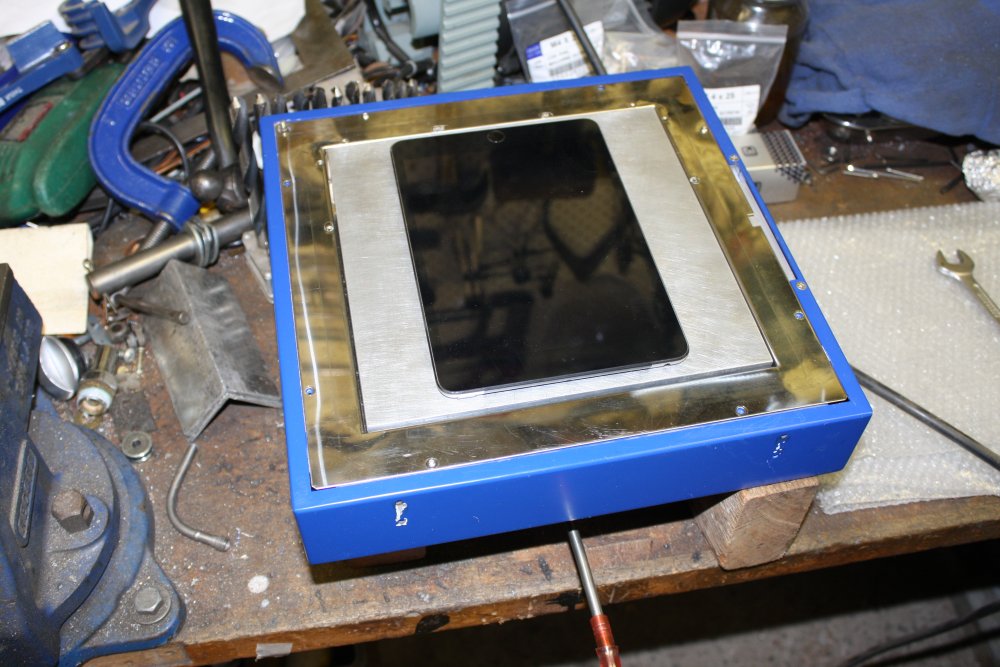
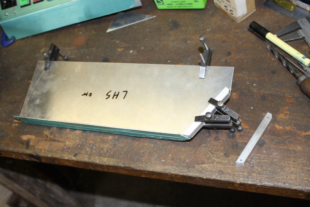
4. Trying it with a vacuum pump and the sacrificial iPad. It really holds it down well, but does let go once you get an edge levered up. That will greatly improve with any kind of flexible edge seal. Something I'll experiment with once the gadget is complete.

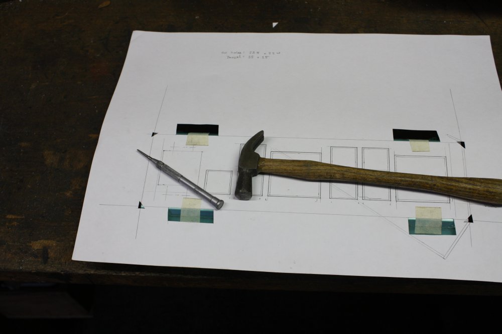
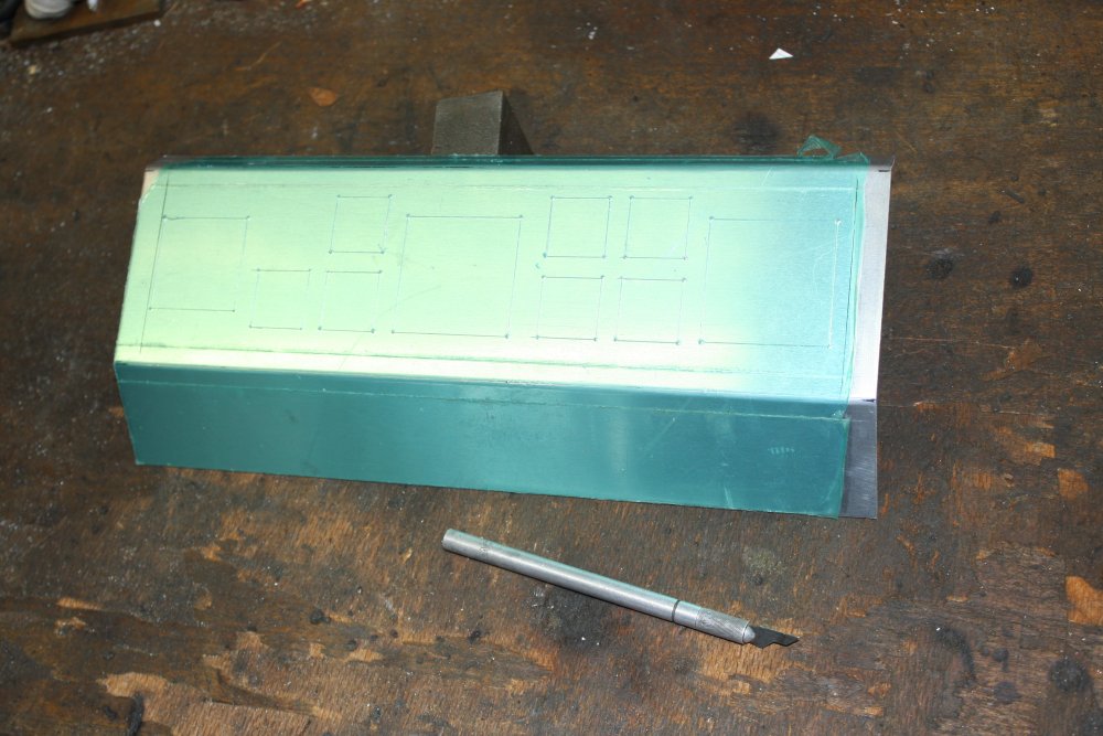
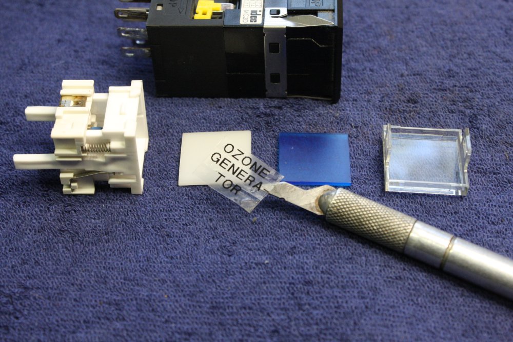
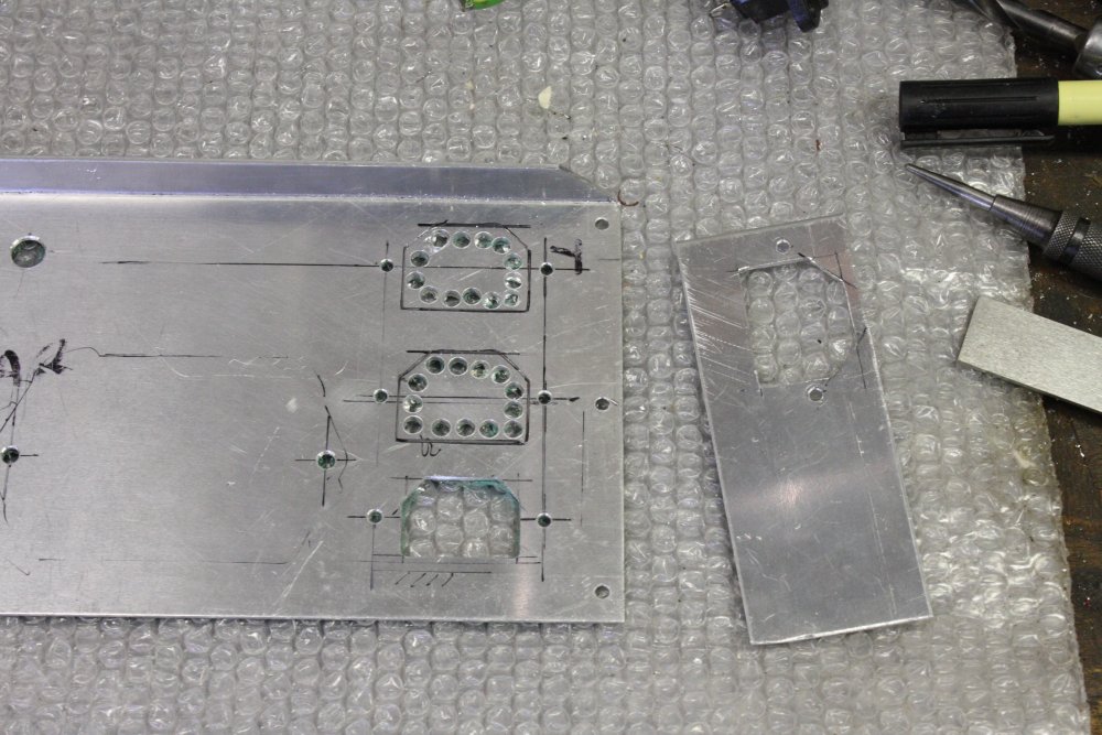
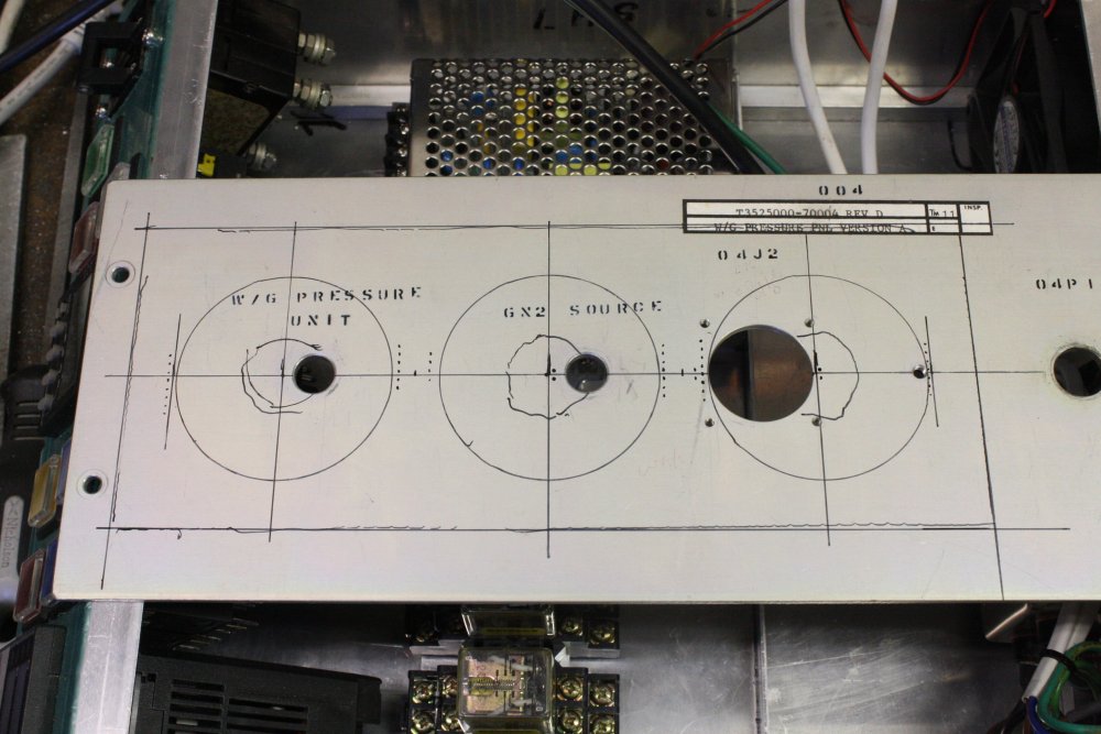
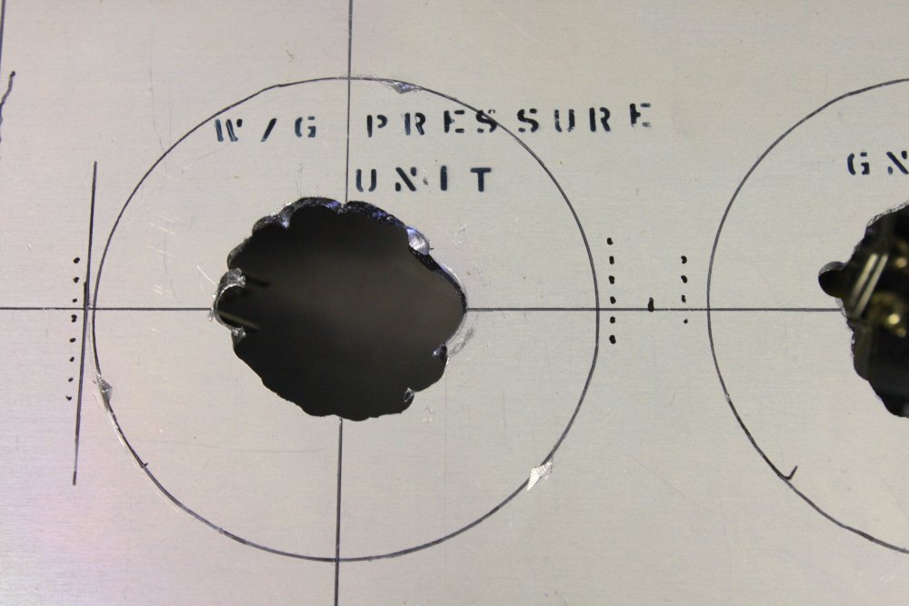
2 - 4. Getting the layout onto the metalwork. Accurate drawing on paper, tape the paper to the metal, small punch marks at cutout corners, score cut lines with a scalpel.
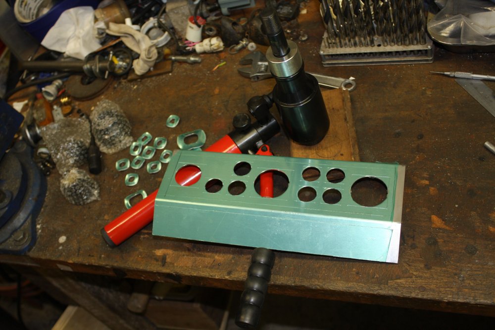
2. Luckily there were dies of a good size for the needed square holes. All done here.
3. Lots of tedious hand nibbling tool later...
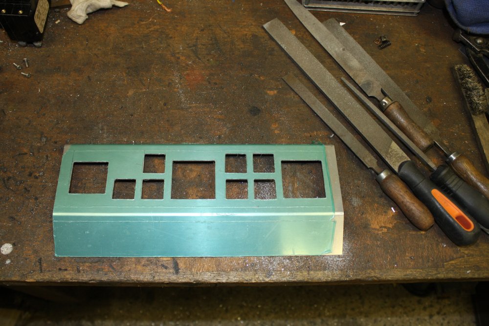
4. And more tedious hand filing, for neat edges and final fit.
5. End result. I'm leaving the protective film on where I can, until the very end.
2. Most edges will be made with 10mm square aluminium sections. These allow for tapped screw holes. They are solid and can also be replaced if required, unlike tapped holes in thin panel flanges.
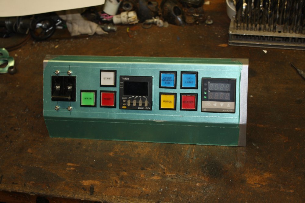
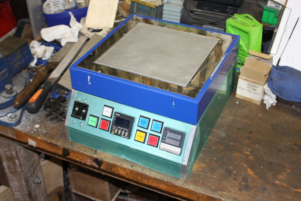
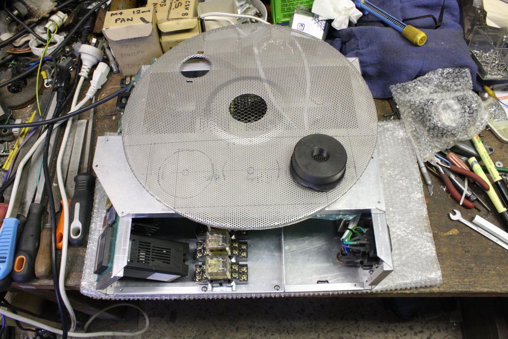
3. Just stacked there, as a trial of what it will look like. Hmm... not bad.
4. The chassis mostly complete. (Minus most of the stuff that goes in it.)
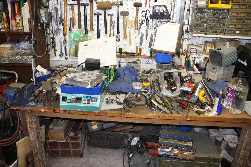
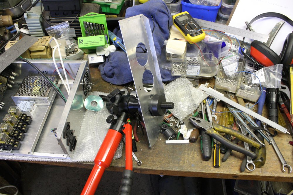
4. Snapshot of the workshop bench at this stage. There are three other projects buried under the stuff related to the hotplate project. Not much workable free benchtop left, but it's adequate.
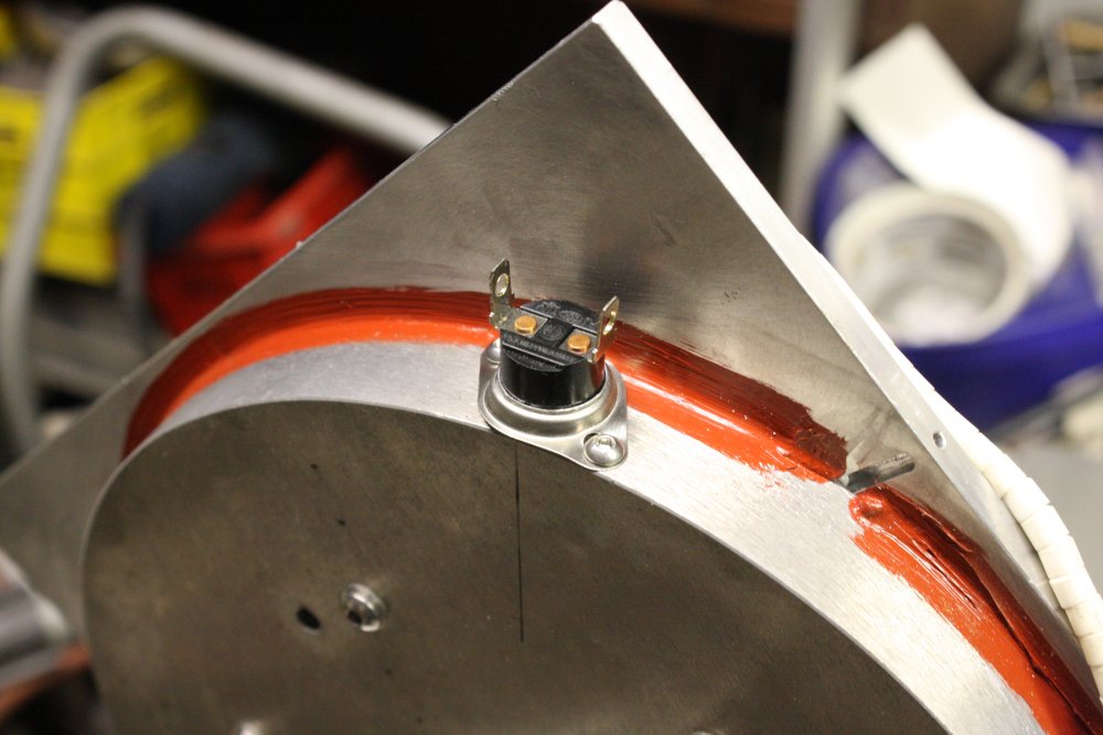
2, 3. Adding an over-temperature safety cutout to the heater block. This is a salvaged one, apparently set to around 180° C. It also has a bakelite body. In future I'll find a ceramic body one set for 300° C.
More fingers-crossed drilling into the block. Still missing.
4. The thermocouple probe fitted.
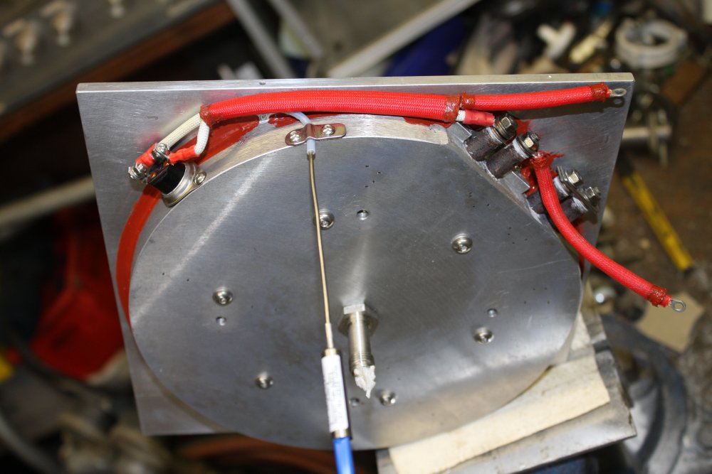
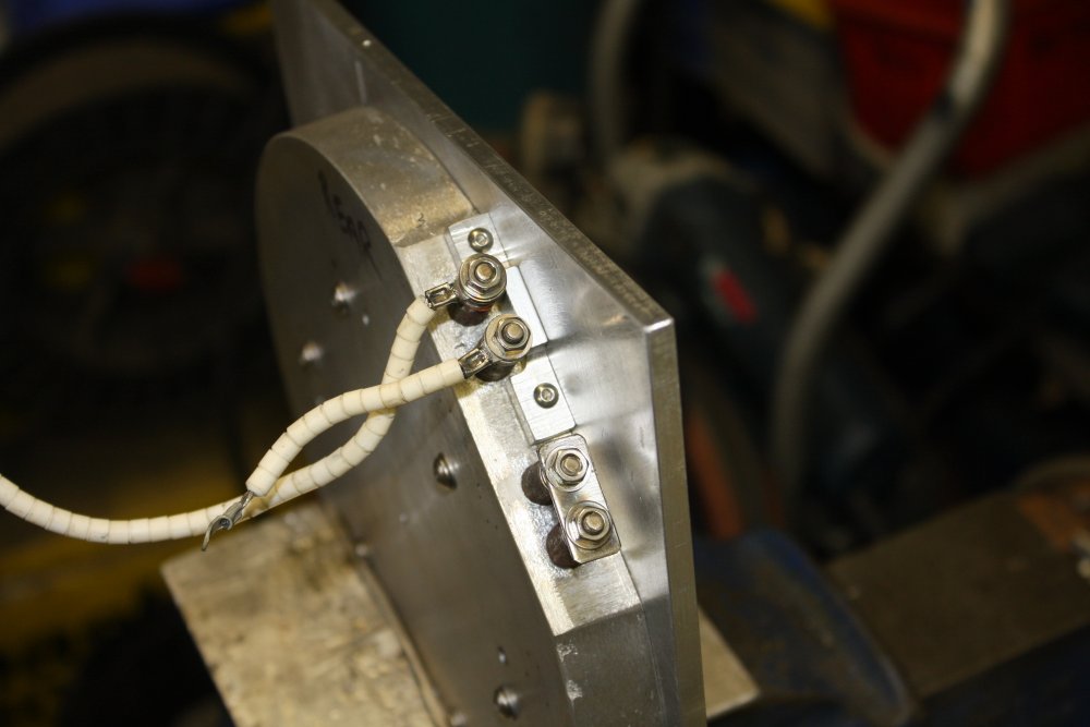
3. The original wiring was wrong lengths and too inflexible, so I redid with high temp silicone-insulated wire, plus two layers of fiberglass braid sheathing. The less than ideal parts are the standard crimp lugs, with plastic sleeves. Those will probably have to be redone in future with high-temp lugs (all metal, special nickel alloy), to run this between 100° C and 300° C. The fiberglass braid tends to fray at the ends, so secured with some silastic.
4. Hotplate plus wiring assembled into the stainless steel carrier.
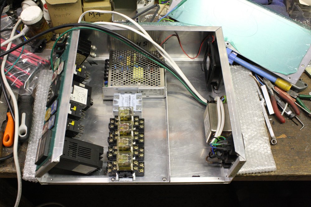
3. Now for the circuitry. Rather than make holes in the base, I'll make an internal plate to carry the components. When I was making the case sides, one turned out wrong and I'd discarded it and remade. Now I can use that piece here, so no waste.
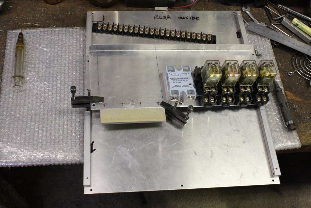
2, 3. And attaching it.
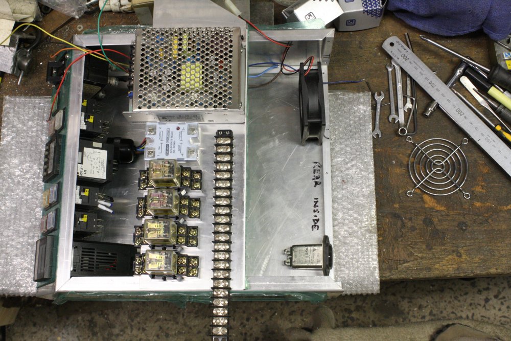
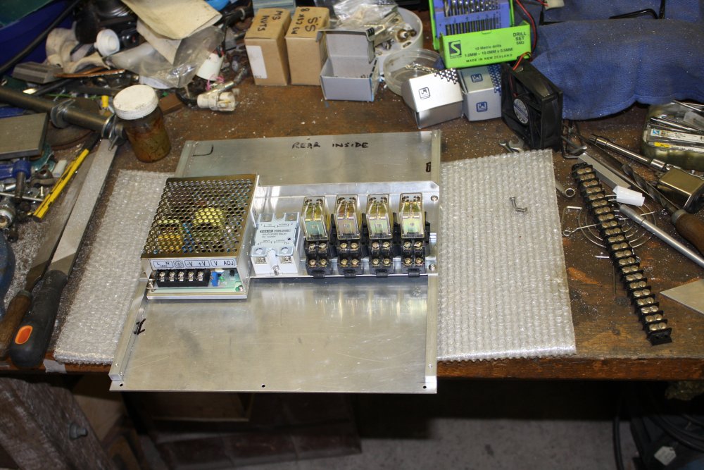
4. Mounting the power supply.
5. Circuitry plate mostly done. Not yet sure if I'll add a terminal strip or not.
About the buttons
The illuminated buttons used in the Blue Thing are very nice. But a few things about the design of the machine were quite odd.
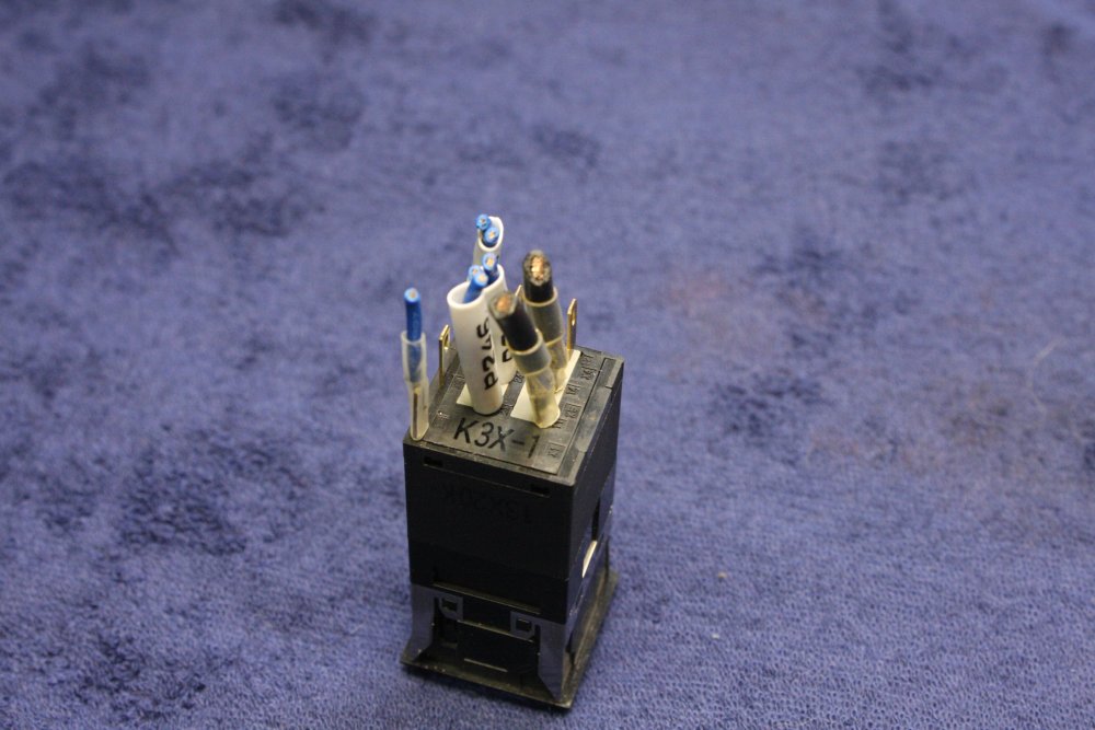
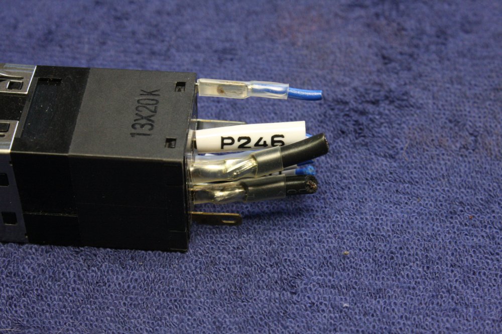
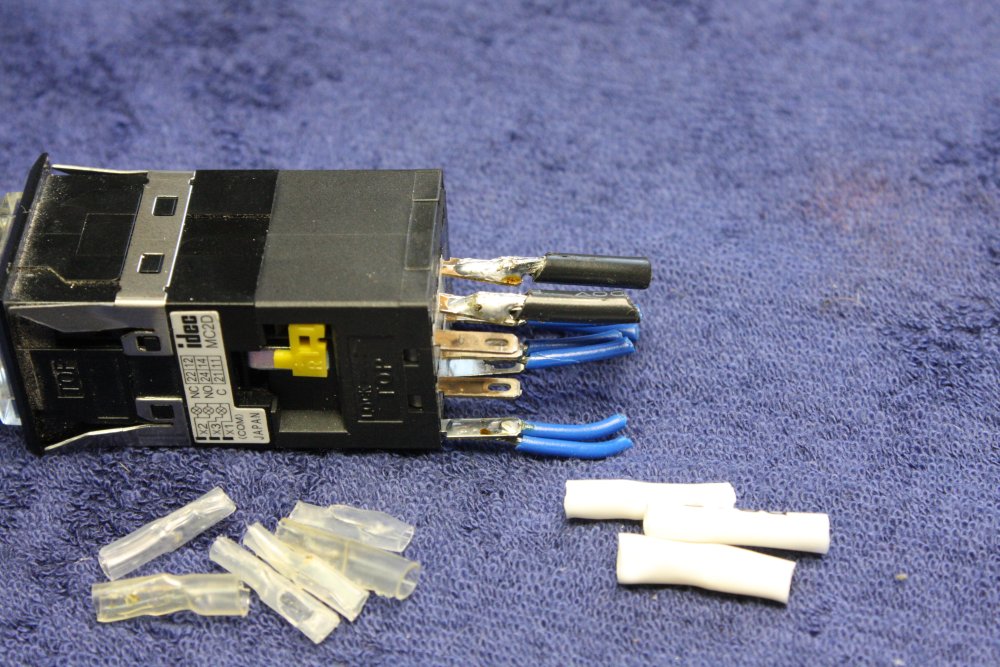
2, 3. But here's something that is a total giveaway of severe tech-nubie nature of the designers. All wires to solder tabs like on these switches, are plain butt soldered. There's no attempt at all to anchor the wire in the tab holes. The mistake here is that solder joints under tension are not strong. They tend to fracture over time. The reason the tabs have holes at all, is that wires are supposed to be passed through the hole and folded back, so the wire itself provides the mechanical strength of the joint. Then the joint is soldered.
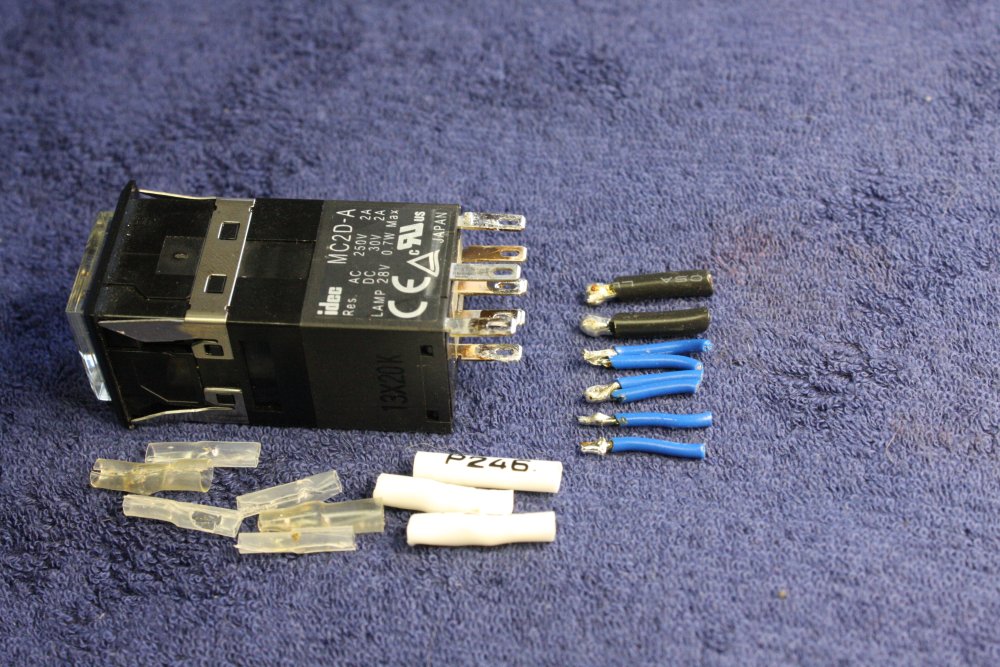
These thick wires don't fit through the tab holes. Even when they did use thinner wire they still didn't use the tab holes. Just butt-soldered them all. The plastic insulating sleeves won't stop the solder fracturing.
It's a terrible construction.
4. All cleaned off now. I'll be doing properly anchored joints, so I need the tab holes open.

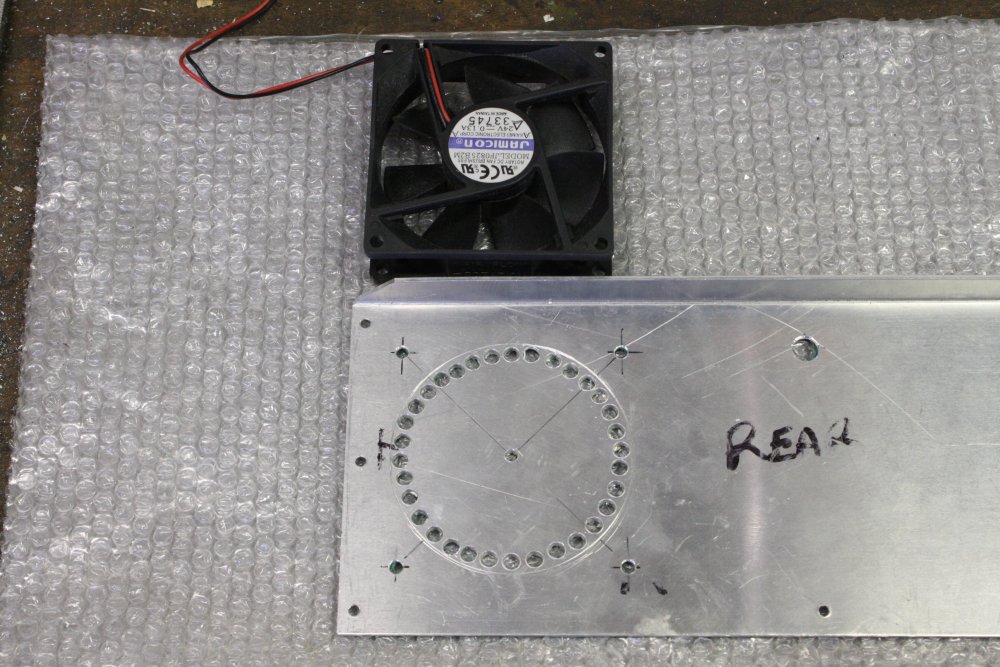
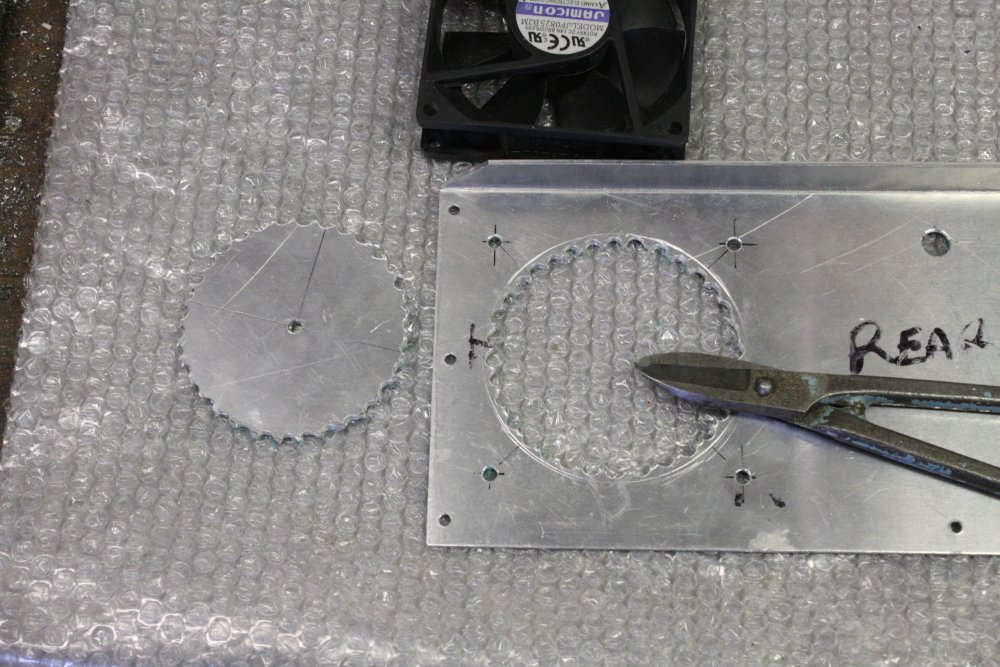
2 - 4. I don't have a hydraulic hole punch or hole saw big enough for the fan hole, so it has to be done the slow way. Scribe a circle, drill holes, snip between the holes, file rough edge out to the scribe line.
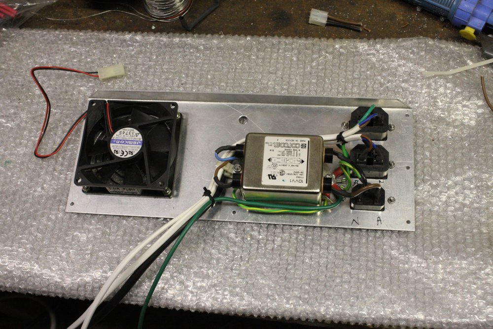
5. Tentative layout for other parts on the rear panel.
3. Trial fit. Oops, too small a radius on the hole bottom corners, so they are slightly visible. Oh well.
4. Back panel wired.
5. OK, it's about time I drew up a propper wiring diagram. Also the side panel has to have an air vent cutout.
Side Vent
As usual, 'small details' left till last turn out to be a pain.
The rear fan sucks air in, and there has to be somewhere for air to exit. When I began the case I'd known a vent on the RH side would be best for interior airflow, but had left the vent design for later. Apart from thinking I'd use a wire mesh, with a securing frame. I have some stainless wire mesh, and expected to use that.
2. Punching the holes. This part is easy. At this rate I thought I'd be finished the vent in a few minutes.
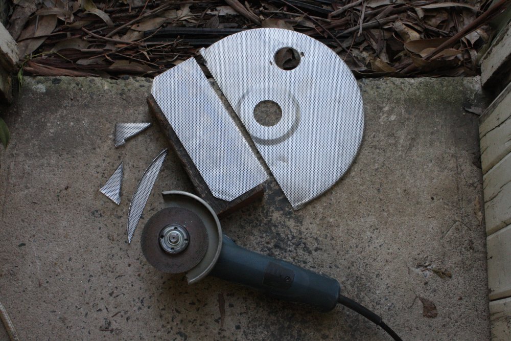
3. Next to cut that piece of stainless grill. First tried using the big tin snips. Nope. It's thin, bendy, and very tough. Tends to just fold rather than cut. Next I tried the big guilotine. Same result, except now I have a sharp fold right across the piece, where I wanted a cut. All right then... I flattened it out again somewhat, and applied what never fails — the angle grinder with a thin cutting disk. After cleaning up the burs, it's done. Now surely it will be just a few more minutes.
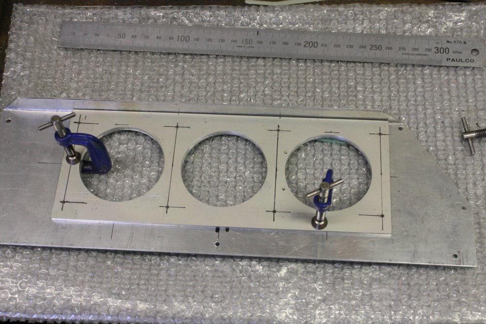
4. For a backing plate I found this old 19" rack equipment facia. By luck, the holes I want mostly cut out the existing holes in the plate. I shall just apply the hydraulic hole punch again, plus cut the outline, too easy. I don't even need to make neat holes for the draw bar, they can be rough as guts because the cutouts get thrown away.
5. Ha ha. The theory collapses. While hacking out the draw bar holes, I'd noticed that this sheet is some quite hard aluminium alloy. Something like duralium. It's from an aviation/military origin, so maybe they just casually used a fancy strong alloy for no reason other than they had sheets of it lying around.
Anyway, the hydraulic punch can't cut it. After the die makes the three small dimples around the circle here, it stops. Releasing hydraulic fluid via some over-pressure bypass, so pumping achieves nothing.
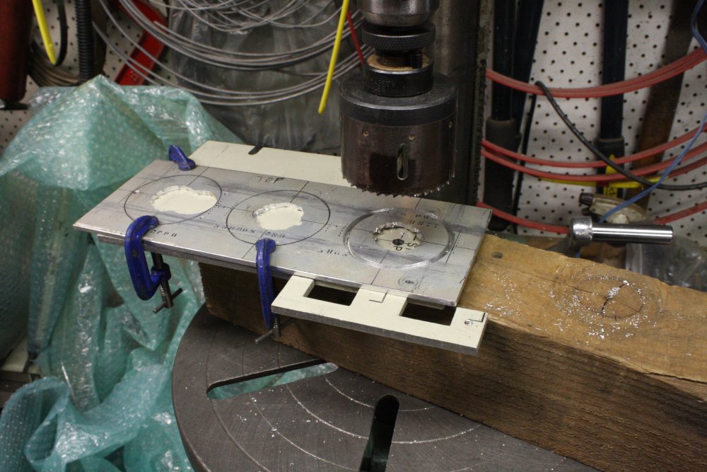
2. At this point I was resigned to to drilling a lot of small holes around the outline, then hand filing the big hole. But just in case, I checked my hole saws set. And I do have one just the right size. But... hole saws need a center pilot hole, and I'd already cut out the centers, darn it. Solution: clamp on a bit of scrap, to provide the centering hole.
3. Transfer drilling the mounting screw holes.
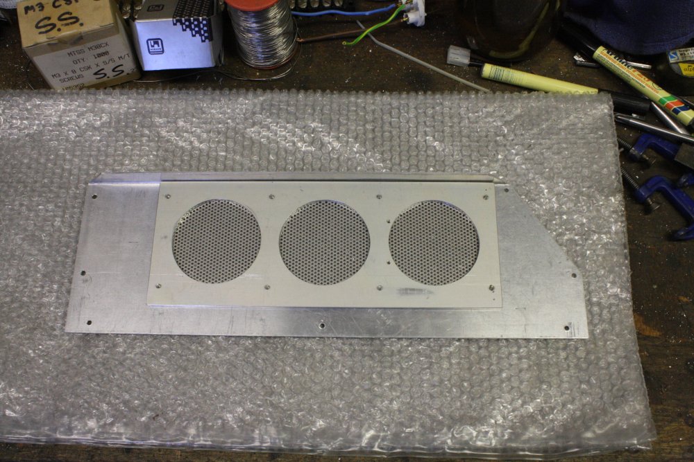
4. Mesh in place.
5. Done.
Just some depressing time-drains like this auction-related drama.