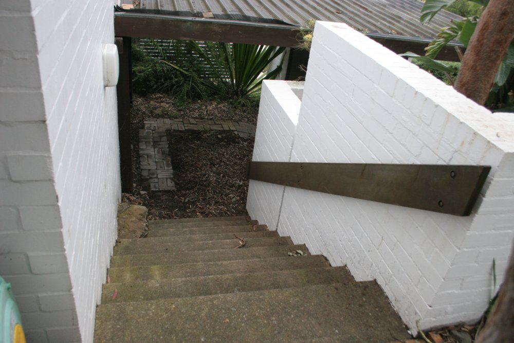
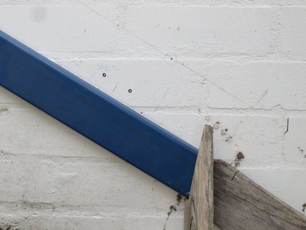
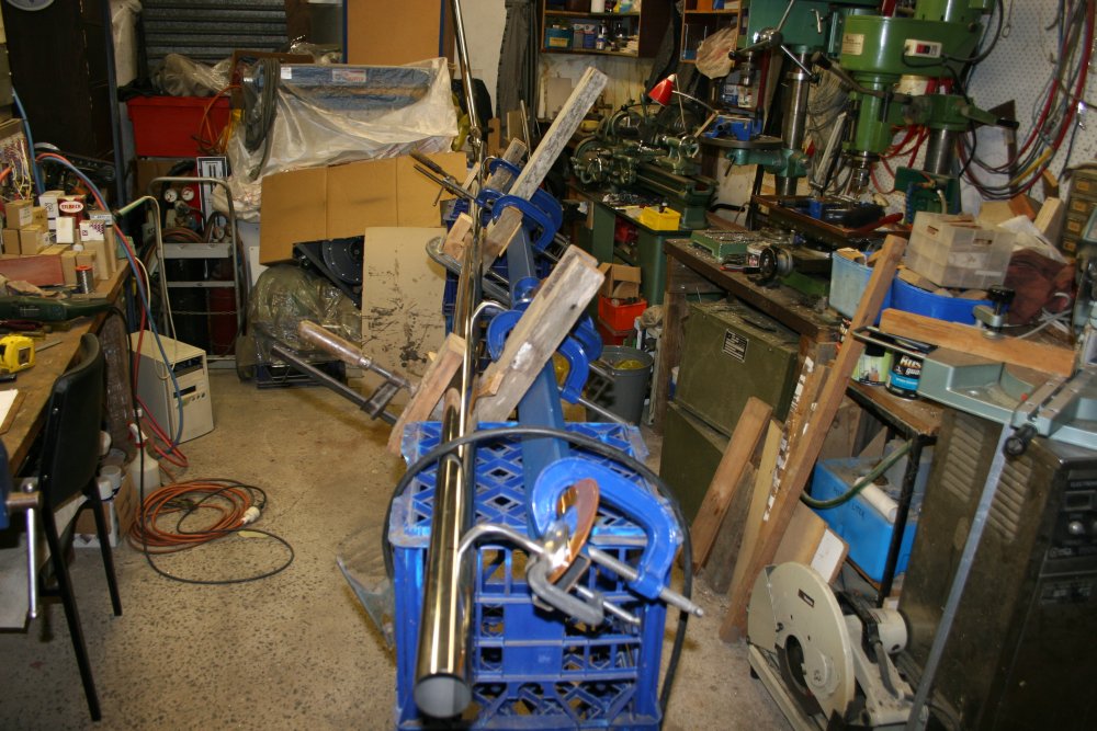
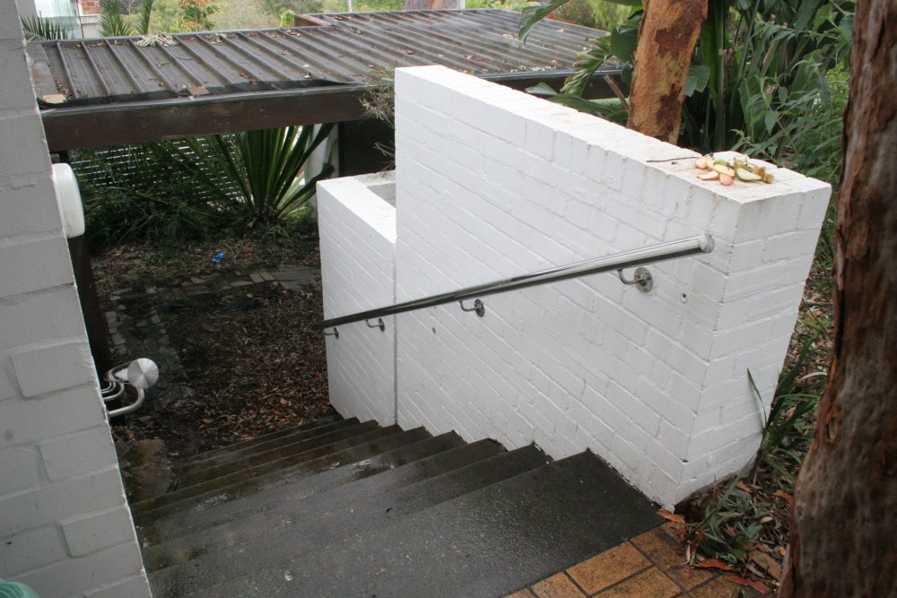
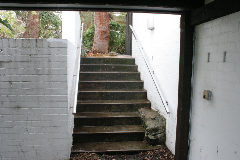
My mum is 86, and getting a bit unsteady on her feet. The other day she had a fall on some outside steps leading down to the carport at her home. No serious injury, just a sprained shoulder. However there's obviously a need to improve the safety of those stairs.
 |
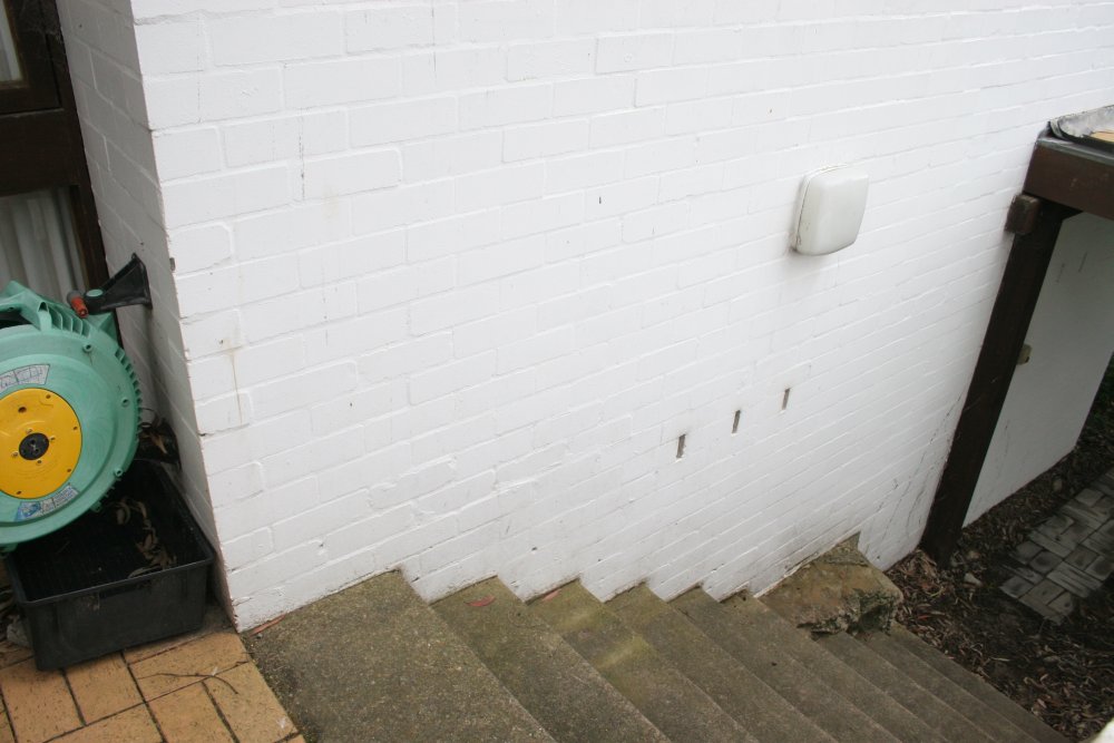 |
Both sides of the stairs are brick walls. Presently they have only a wooden beam hand rail on one side, nothing on the other. The wooden beam rail is not the best, since it's too large to wrap a hand around.
The aim is to make a pair of stainless steel tube railings, same on each side. Back in 2009-10 I'd built some stainless steel railing for her rear laundry door and steps, that had worked out well. It had taken me a while then to construct a couple of special purpose tools needed for welding stainless tube. One was a pipe rotating welding setup, plus a jig for initial tack welding joins. The other was a gadget to allow precise grinding of weld beads on a pipe, to get a flat finish.
These railings can be simpler - no bends for one thing. The only not-quite-obvious part is the mounting. How hard can it be? Surely there will be standard wall-mount brackets available for exterior stainless railings, on brickwork?
Ha ha ha.... no. Surprisingly, trips to my usual steel and fastening suppliers, then a lot of web searching the next day turned up nothing. The steel warehouse (where I'll buy the stainless tube for the railings) has exactly what I imagined, but only in galvanised steel. A round disk, with a 90 degree elbow rod welded to the disk center, three holes in the disk for dynabolts, and a domed cover that clips over the disk to hide the dynabolt nuts. They also have lots of other hardware for stainless railings, such as elbows, Ts, end caps, etc. But no bolt-on elbow wall mounts. The closest they have is a range of sizes of plain stainless steel round disks.
Similar story at the 'Fasteners' specialist nearby. They have a wonderful range of stainless steel fittings for balustrades and wire rope accessories. But no elbow brackets.
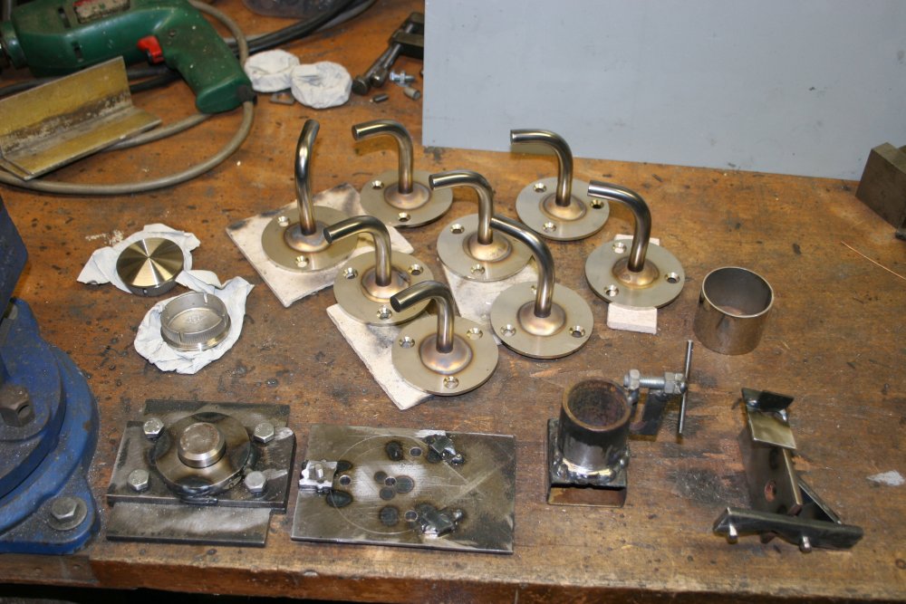
Which means I'm going to have to make them. Eight of them. Sigh.
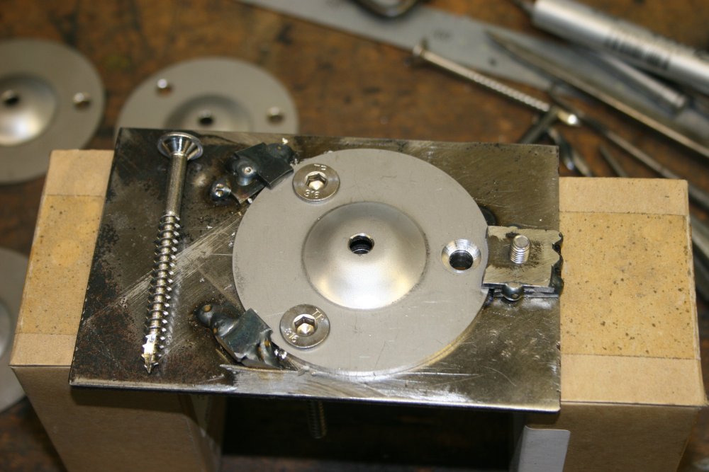
Even that isn't easy to see how to do. I can't make those domed stainless covers, so the mount plate will be exposed. I don't want exposed dynabolt nuts, or even bolt heads. This means the fasteners have to be some sort of neat looking domed or flat head screw, using heavy duty expanding plugs in holes in the brickwork.
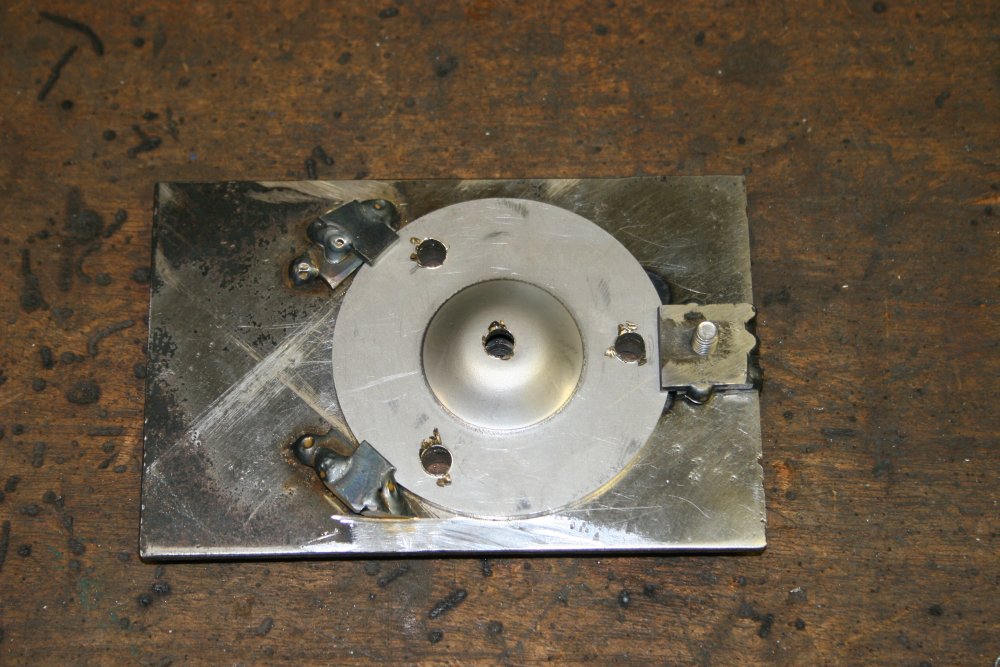
Another problem is how to weld the elbow bar to the disk? My stainless TIG/MIG welding is definitely not neat enough for obviously visible welds. So the mounting plate to bar welds have to be on the back of the plate. But that can't be a flush surface, with a small V-weld ground flat, since that doesn't reliably leave enough metal to ensure the join will never fail under the kinds of load a railing might have to take.
It has to be a solid fillet weld, with all weld metal left in place. This means the disk has to have a 'bump' in the middle where the rod attaches, so the weld is up off the plane of the brickwork.
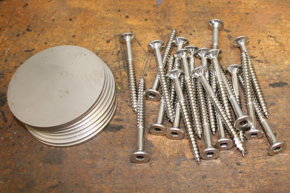
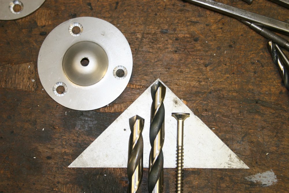
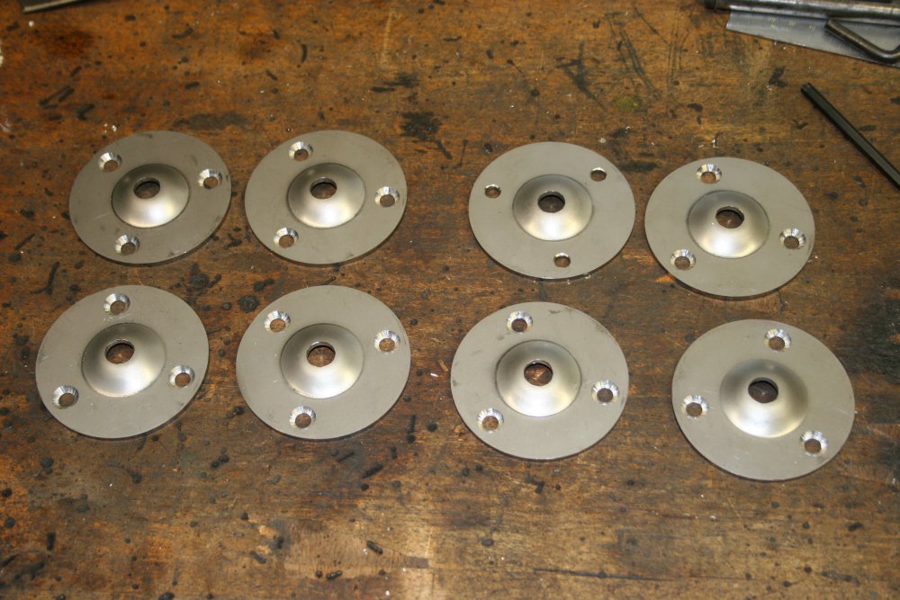
The most suitable disks are 3mm thick, 76mm dia 316 alloy stainless steel. Putting a neat, reproducible 'bump' in these isn't going to be easy.
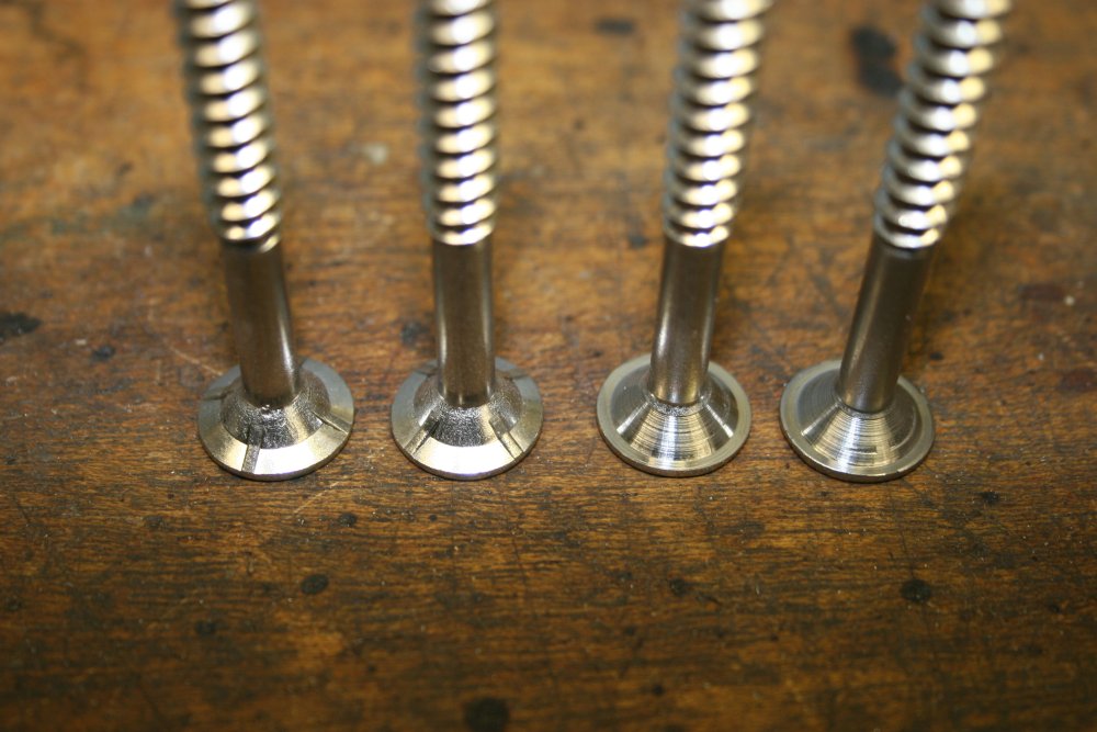
As for fasteners, the best I can locate are stainless 14G 'timber screws', which have a kind of bugle head. It's a flat top with a hex socket. However the countersunk faces have small ridges and a non-flat rim. They also have a 'self tapping' slot at the thread point, that will not work well with rawl plugs. For those the screw has to expand the plug, not chew a hole through the middle of it. So all those little details on these screws will have to be modified.
 |
 |
 |
 |
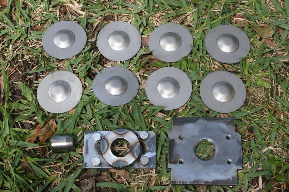
 |
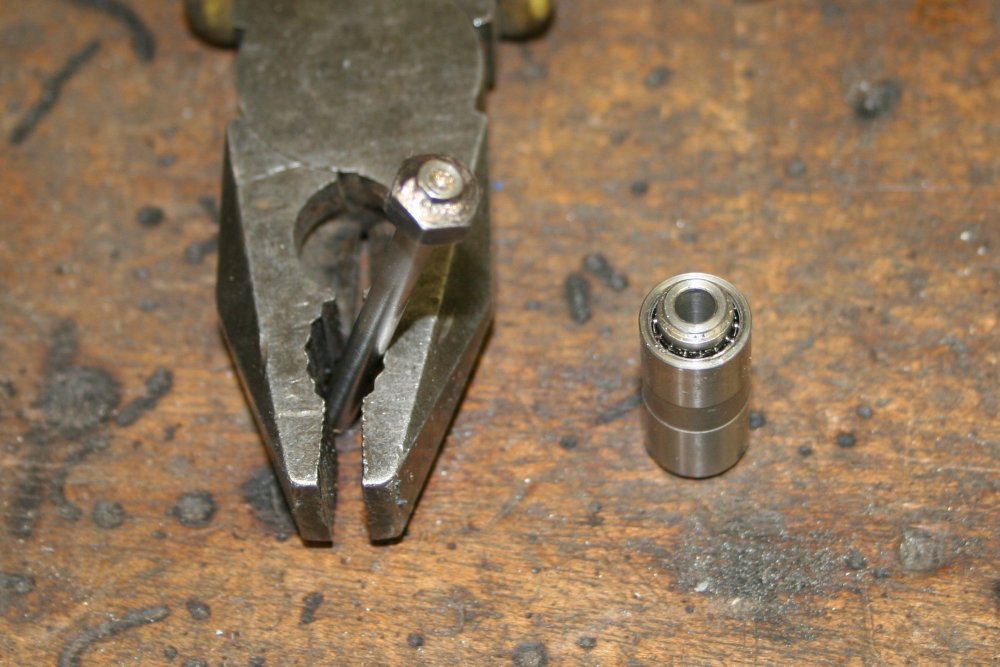
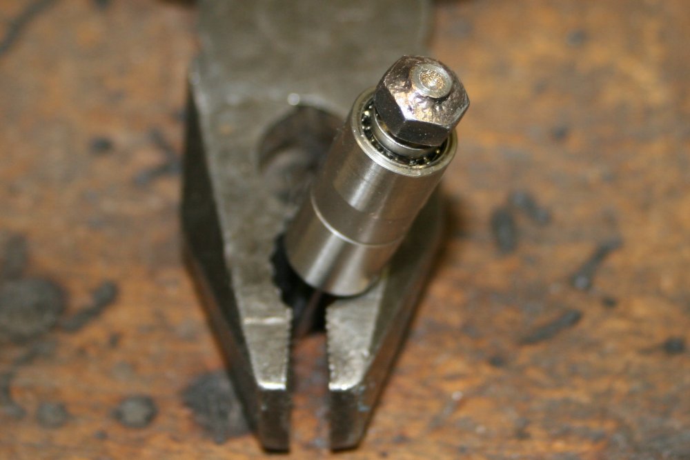
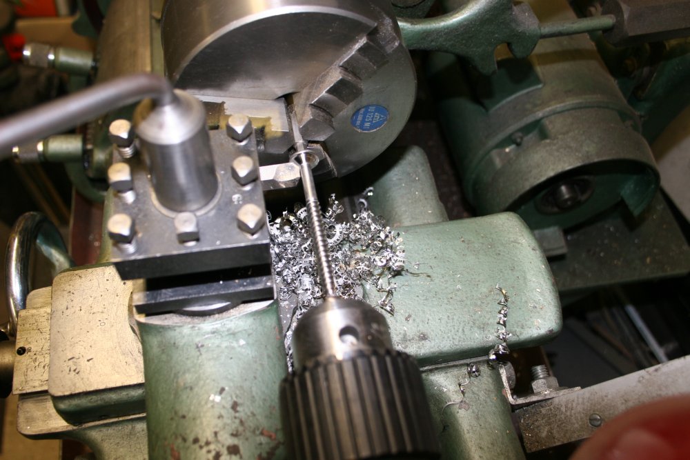
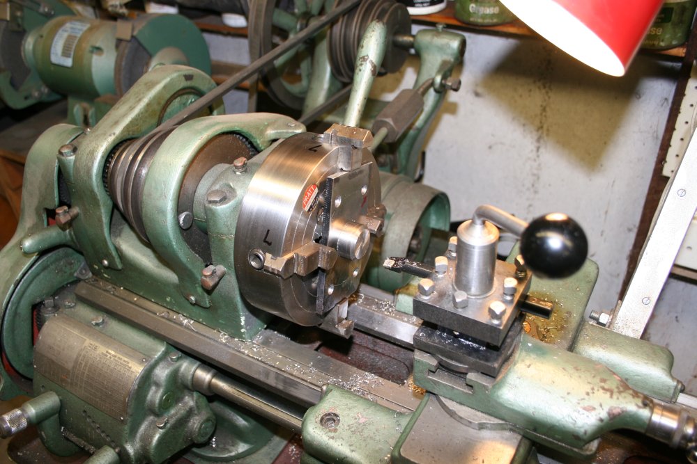
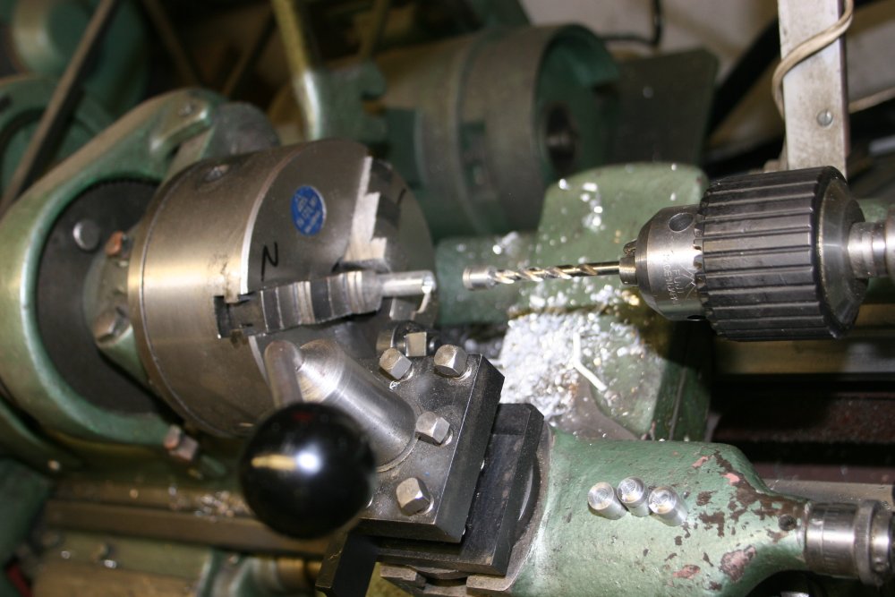
The disks and screws. First job is to modify the screws. How do you mount a wood screw in a lathe, for machining the countersunk profile to what's needed? The head end is easy — just grip a hex driver in the lathe jaws. But for the pointy end of the screw, there has to be something free-rotating, with a small conical hole in the end to press against the screw point.
And so, the first improvisation of many in this job. A small roller bearing (from an old hard disk heads mount), and a steel rod that fits into the bearing, with a nut brazed near the end as a seat on the bearing, and a little hole drilled in the end of the rod using a centering drill in the lathe. Pic 3 is this assembled.
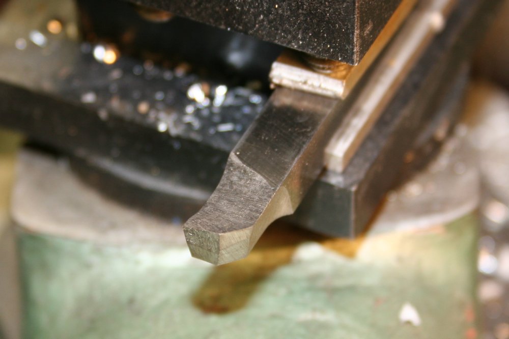
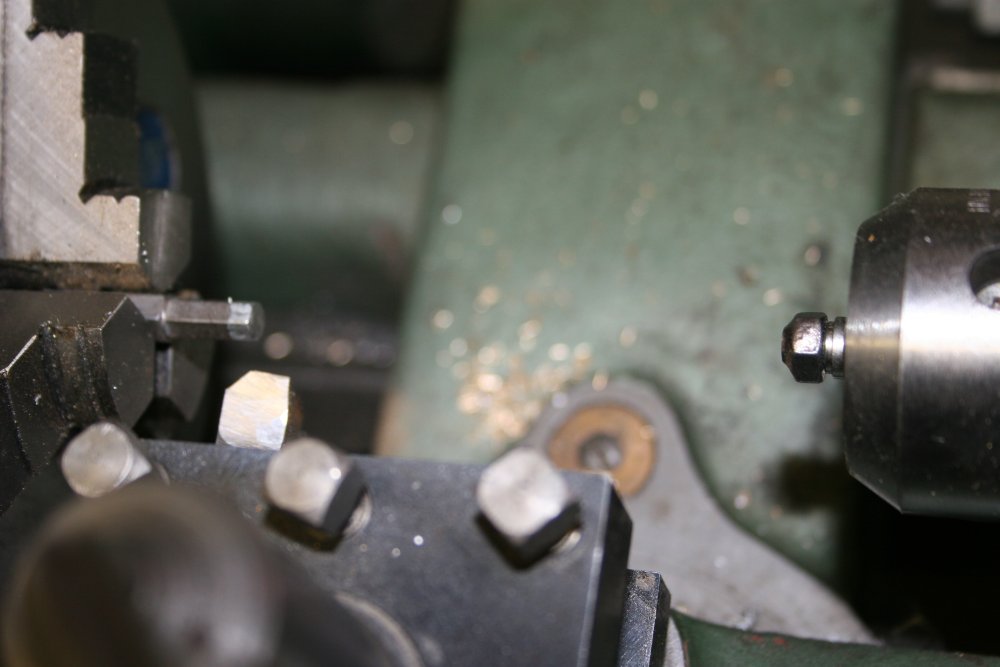
The desired profile of the screw heads is a plain countersink, with an outer flat lip. Pic 4 is a custom cutting bit, ground from a silver steel bar to perfom the correct cut on the screw heads. Pic 5 is the lathe ready to mount a screw.
 |
 |
 |
 |
 |
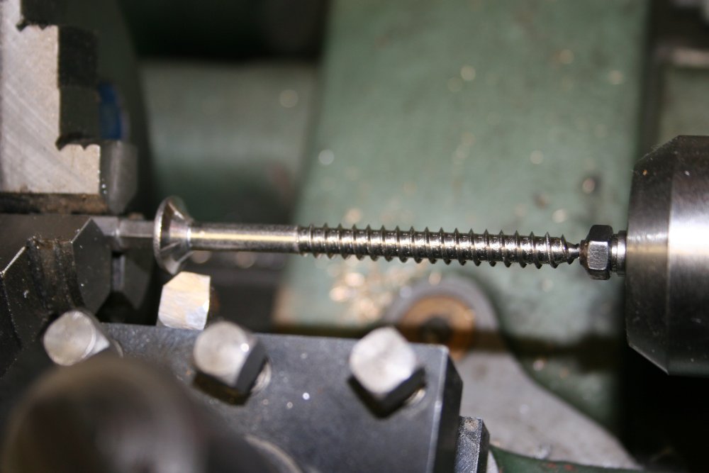
A screw, about to be cut, and finished. This was easy, needing only one fixed depth pass per screw, so the entire 24 (actually I did 25) took little time. Pic 2 is a screw completed. Pic 3 shows the original head, compared to the modified head at right. Pic 4 is the last one.
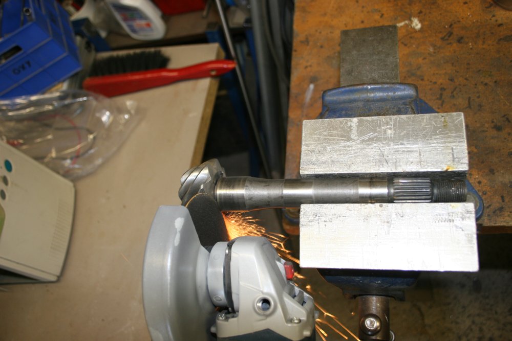
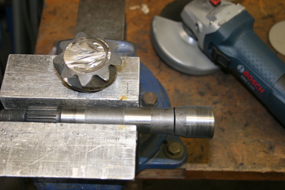
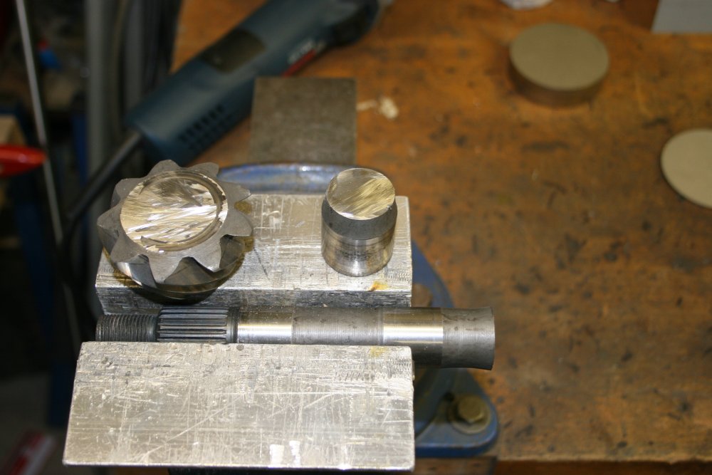
On to 'making the bumps.' Obviously, one thing needed would be a very tough 'bump maker'. Whether I ended up finding a hydraulic press, or just bashing away with a big hammer, the core punch part would need to not deform under the pressure/impacts. Digging through the scrap steel pile I found an old gear shaft from a car differential. This steel should be about right. And the piece of it to make the punch will be the thick shaft, up near the gear. It never ceases to amaze me how quickly a thin cutting disk in an angle grinder can deal with even chunky bits of tough steel like this.
 |
 |
 |
 |
 |
More cutting, and then the 'bump maker' is free. Next I naively tried to turn it to shape in the lathe, using tungsten carbide bits. Nope... This is tough steel, and wrecks the edge on tunsten carbide immediately. Not sure if it's just surface hardened, or tough all the way through, but who cares? I know how to deal with you, Mr 'tough steel'.
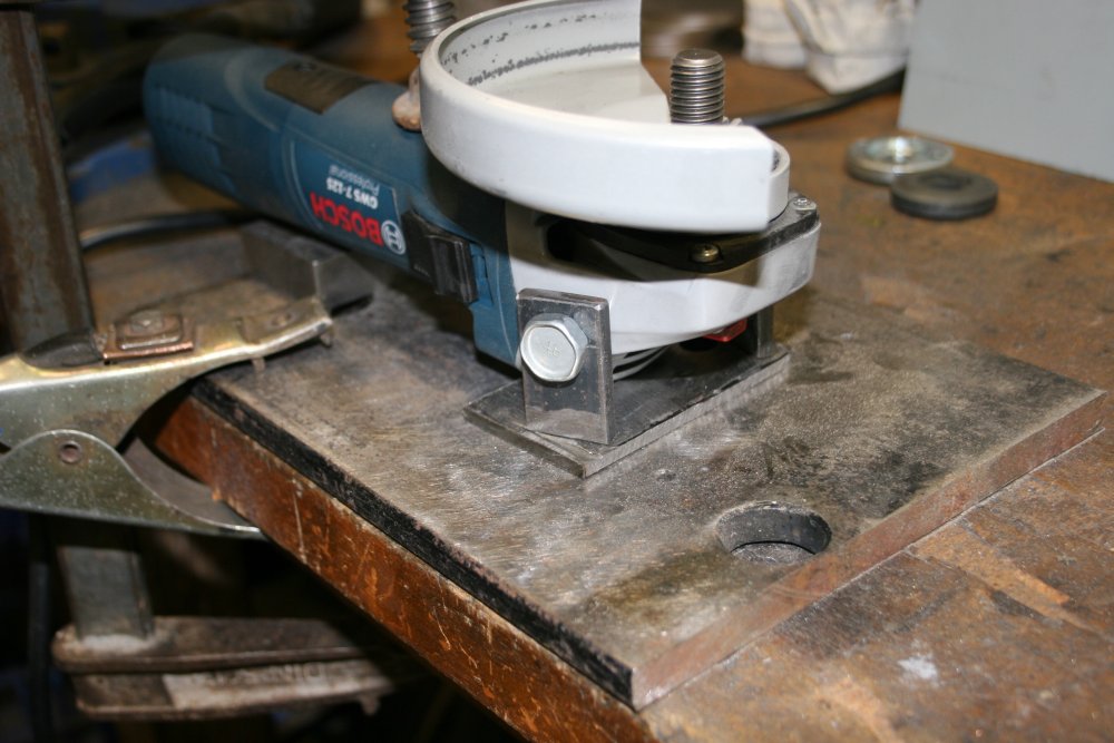
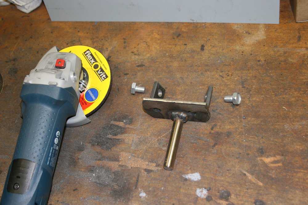
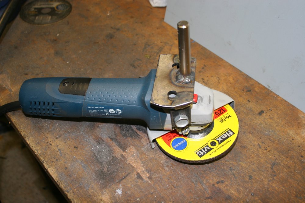
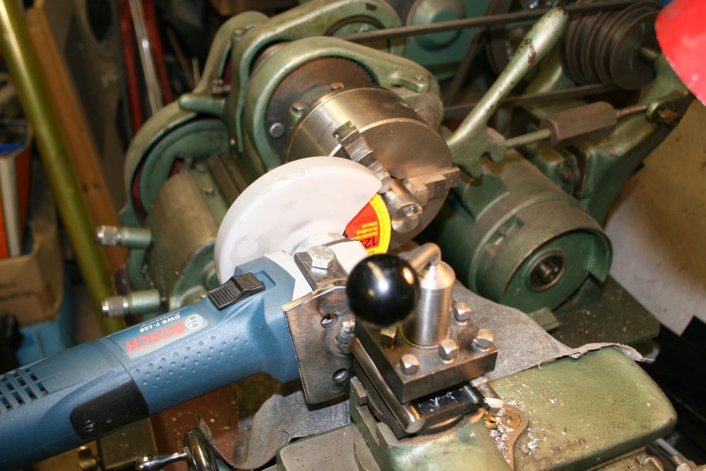
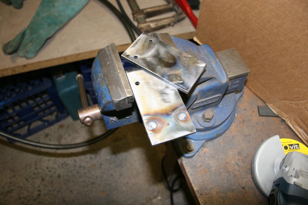
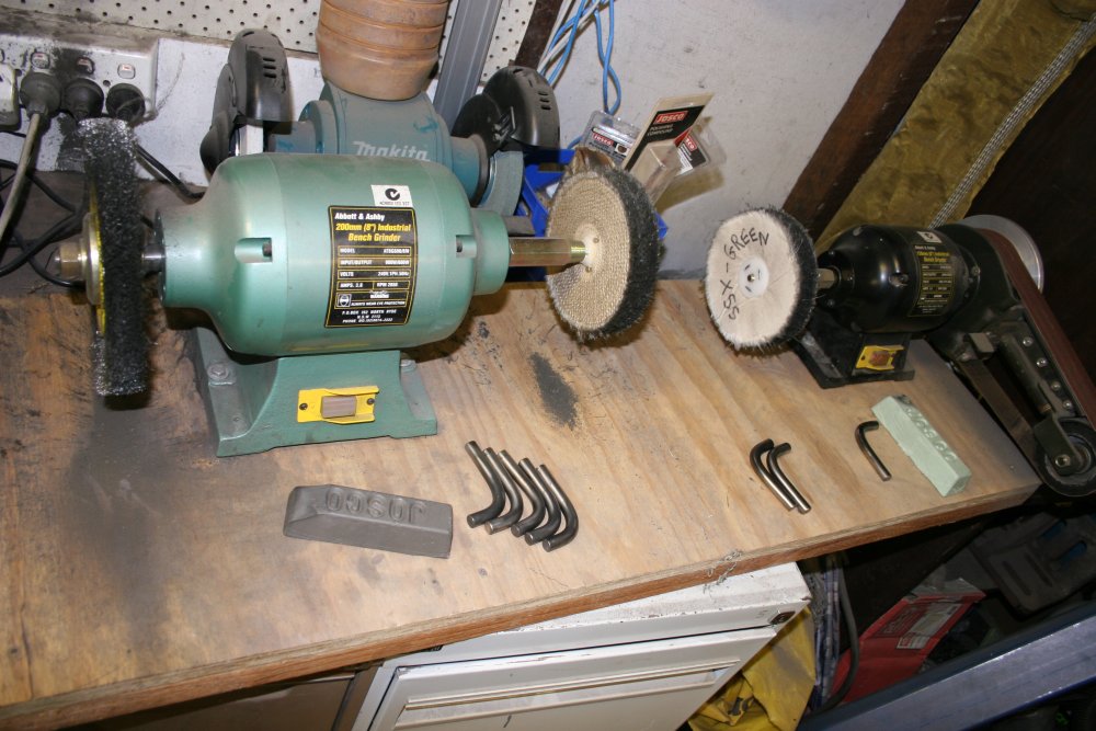
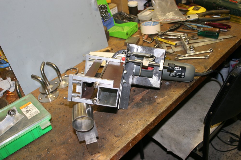
Somewhere I had a lathe mounting adapter for my old angle grinder. But that grinder needs a new main bearing, and so first thing is to make a mounting adapter for one of my new grinders. Pic 3 is the bracket about to be welded. Pic 4 is the completed bracket. Pic 5 is it attached to the grinder.
 |
 |
 |
 |
 |
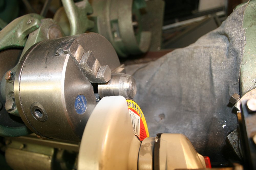
With the grinder mounted on the lathe toolpost, the punch is easy to shape. Makes a spectacular shower of sparks, but I couldn't both feed the tool, and take a photo at the same time. Needed three hands.
Grinder grit is bad for the lathe bed sliders, so there's a piece of cloth covering them. And the cloth is sprayed with water, or it catches fire from the intense jet of hot sparks.
I only ground the punch end to an approximate shape for now, since the fixture it will sit in isn't made yet.
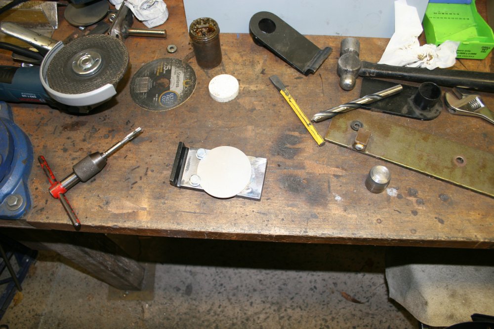
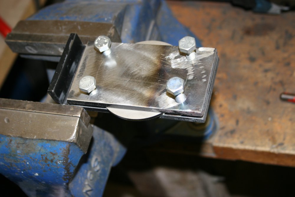
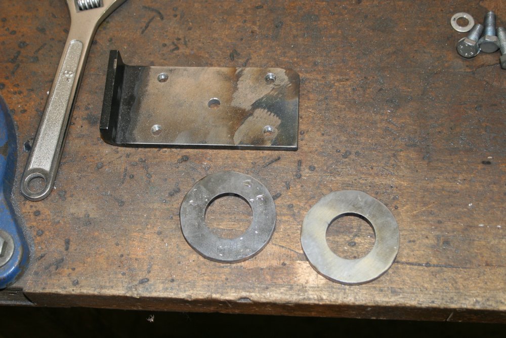
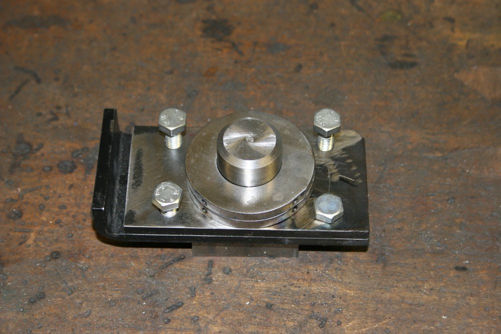
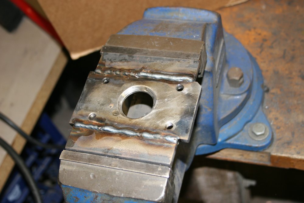
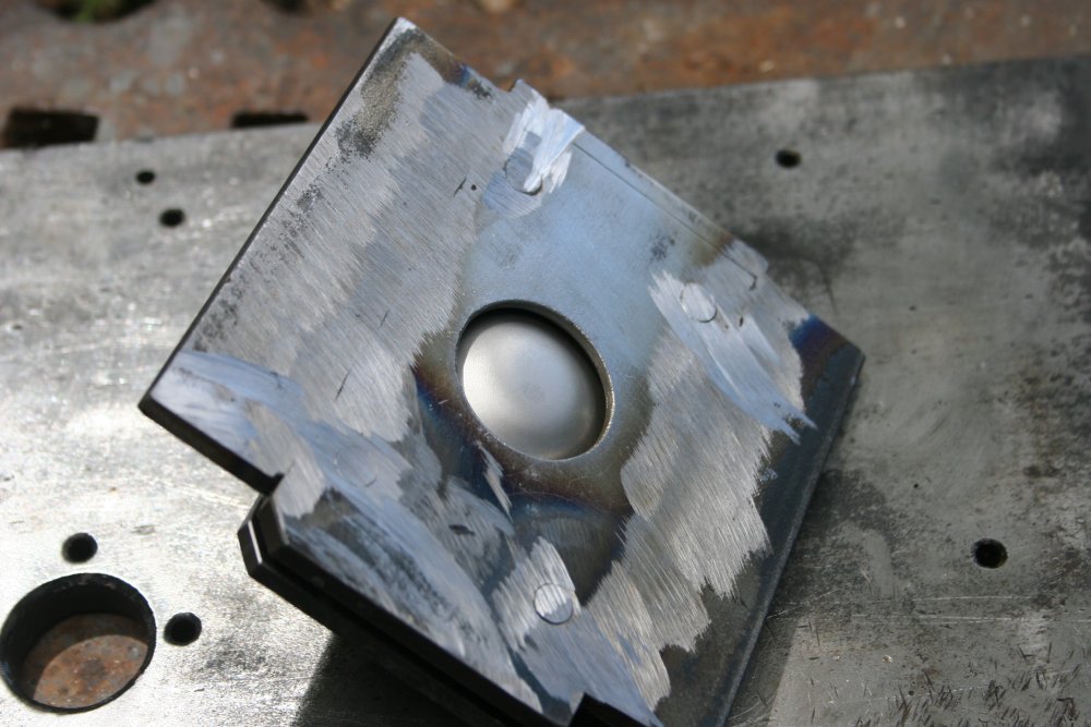
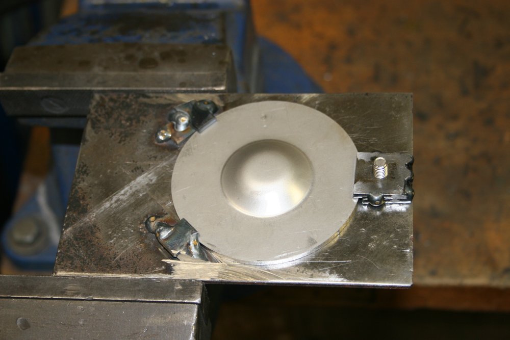
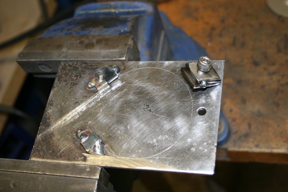
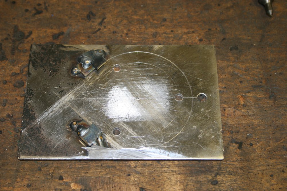
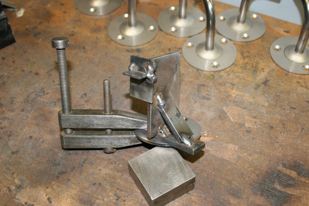
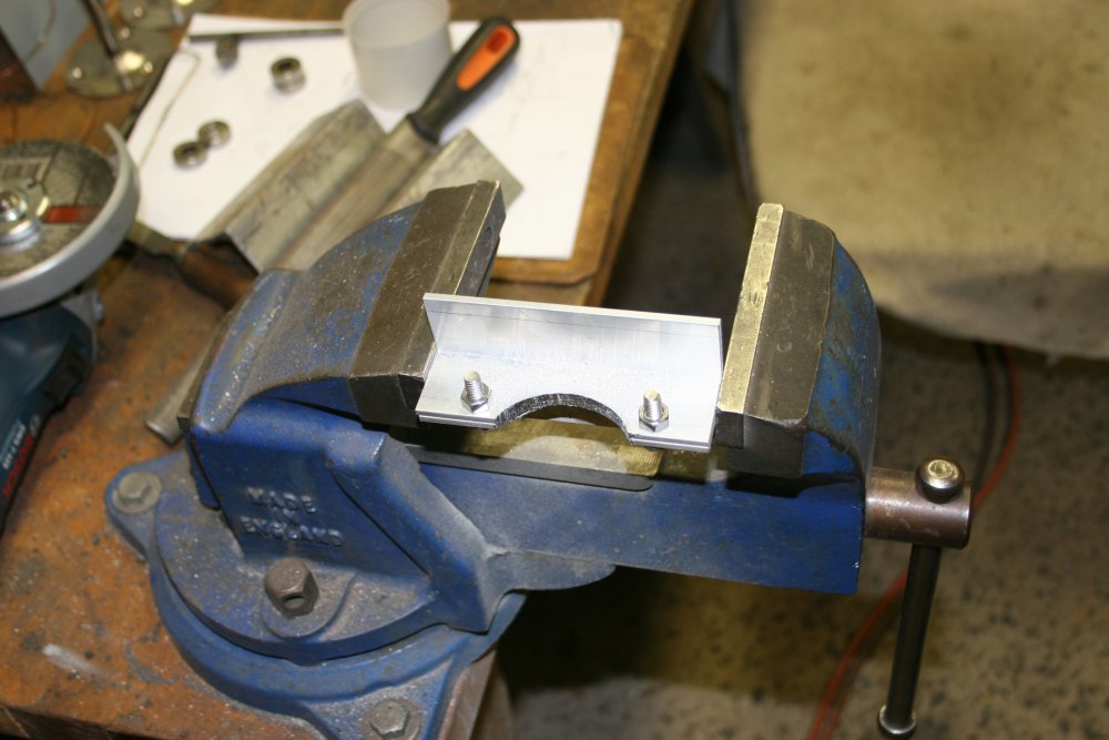
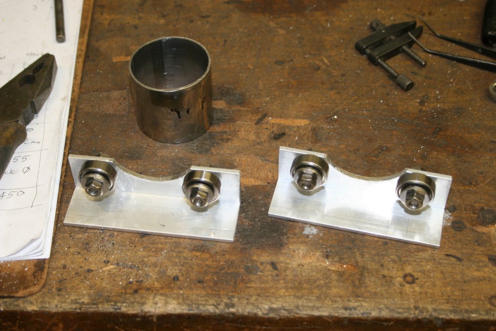
For that, I'd found some usable bits of scrap plate steel. Two matching pieces, with four matched holes, that were almost perfect for the diameter of the stainless disks. But unfortunately, a little too close together. So two of the holes in each plate had to be vanished (with the welder, then ground flat) and new holes drilled in the right place.
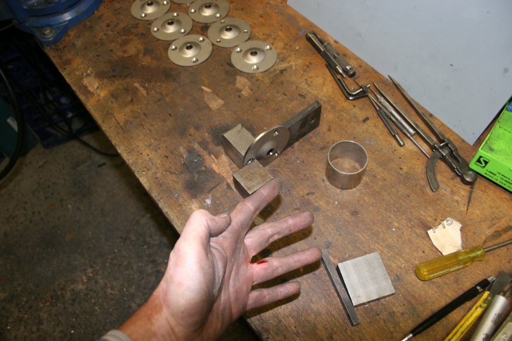
In pic 4 I'm marking the location of the new holes at the edge of the stainless disk. Also in the pic are the two black-painted offcuts from those plates, that happened to have round holes in them that by a fluke are a near-perfect fit for the punch I'd already made.
In the top plate the bolt holes are drilled for M8 clearance, in the bottom plate they are tapped for M8 bolts.
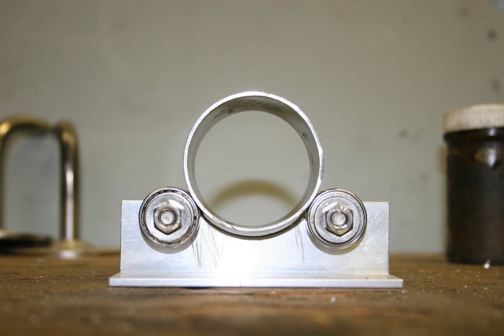
Pic 5 shows the plates assembled with a stainless disk clamped between them and positioned by the bolts.
 |
 |
 |
 |
 |
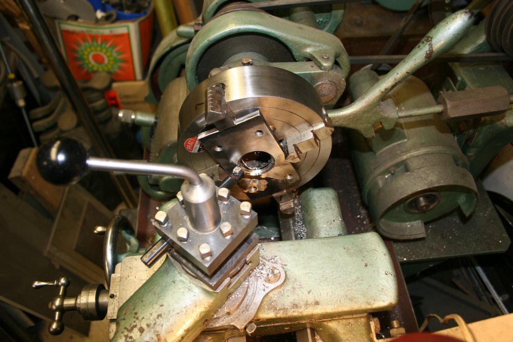
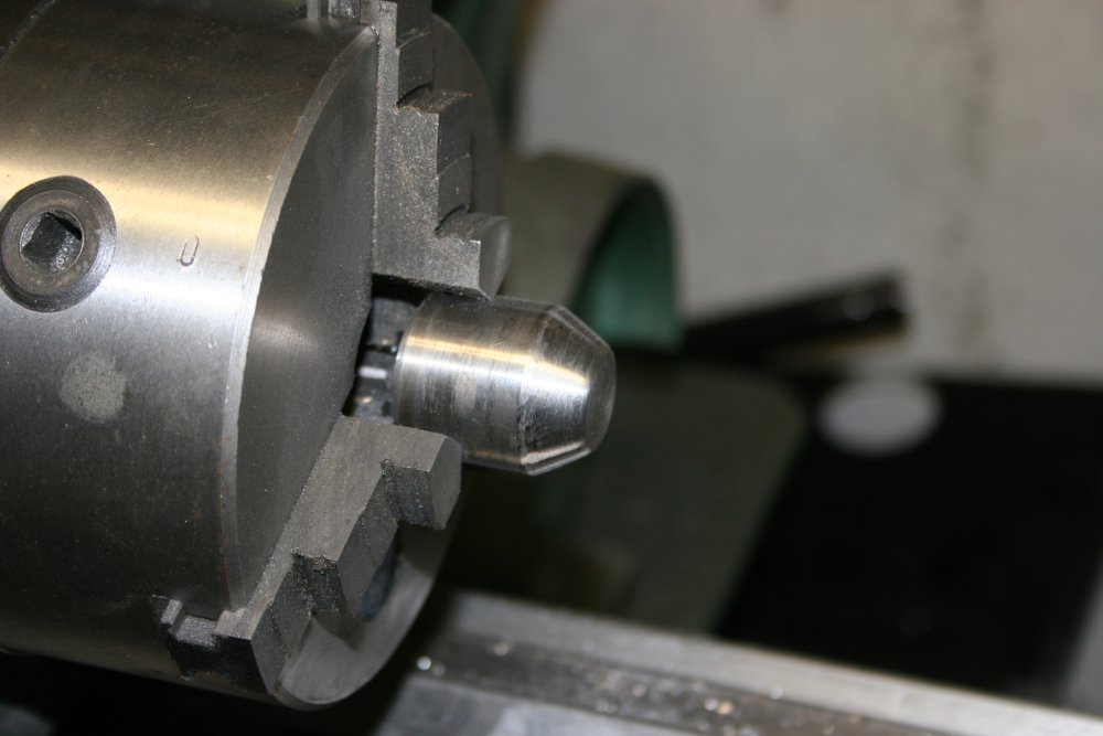
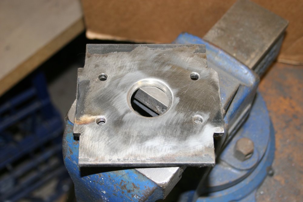
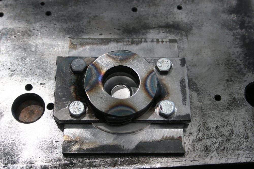
There needs to be something to hold the punch pin fairly solidly and precisely. Pic 1 is those two fortuitously sized holes mentioned before, cut into rings. Welded together these will be the guide extension for the punch. The top plate will also be part of the guide. So cutting the big hole in that plate is the next job.
Pic 2 is drilling a hole in the plate, wide enough for a boring bar. In pic 3, the lathe has a 4-jaw chuck holding the plate, with the hole bored out to fit the punch. Shown fitted in pic 4. Pic 5 is the entire stack assembled, ready to weld the upper guides.
 |
 |
 |
 |
 |
Now to shape the surfaces that will do the work of deforming the stainless disks. I don't want the front of the 'bump' to make contact with these dies anywhere apart from a small ring at the base of the bump. Since all contact will mar the surface finish of the stainless, which will make more work later. It's also important that the pressure points should be rounded, otherwise a sharp-edged weak point could be formed in the stainless sheet. Or even a tear. Also these plates are just mild steel, which is softer than stainless steel. So the pressure points need plenty of backing metal.
Upshot of all that, is the hole in the bottom plate has to be conical, with a rounded top edge. At least it's easy material to machine to a good finish. Unlike the punch, which needs more application of the grinder.
I was a bit worried that the bottom plate sides around the hole were maybe too thin. So I added some reinforcing bars to the edges, then ground the welds flat. Yes, the joint was v-grooved.
 |
 |
 |
 |
 |
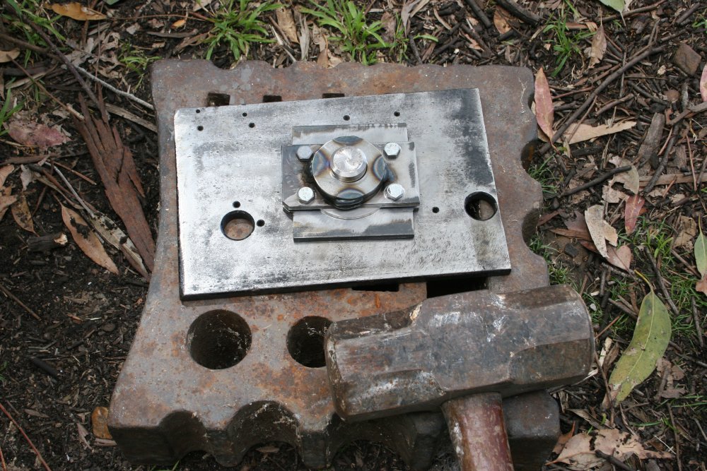
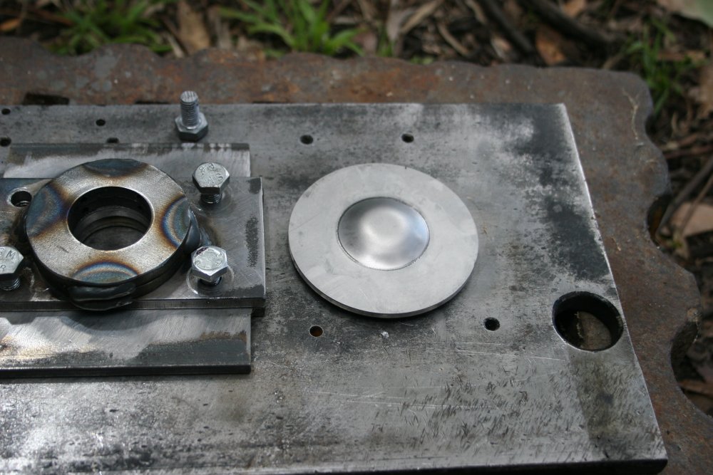
With the upper guide rings welded on, the whole thing is ready to go. My anvil is currently buried under a pile of stuff (still waiting completion of the Forge Shed), but its brother the swage block is accessible. I lugged it outside to serve as a base.
My biggest hammer is a 14 pound sledge. I wasn't at all confident it would be enough, but it was worth a try. Standing back and taking a swing wasn't an option, since the sledge needs to hit the punch as close to flat, centered and in-line as possible. So the method was to sit next to the assembly and sort of vertical-drop the sledge. Not conducive to achieving a massive impact.
But it worked! After getting the hang of striking, it takes about four or five strong blows to get the right sized 'bump'. I was stopping with the bump about half a millimeter short of the underlying plate, since if it bottomed out the surface of the stainless steel sheet would be marked.
 |
 |
 |
 |
 |
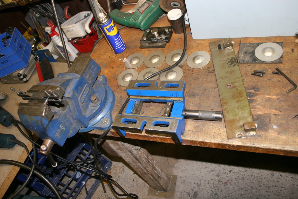
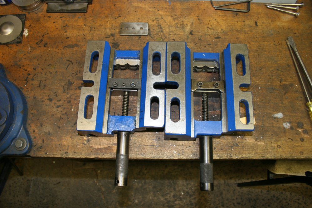
Next day started with a slight sidetrack. I needed to make a jig for drilling the holes in the disks. Found a suitable bit of scrap steel plate, but when checking it would fit in the machine vice I use with the drill press, the vice jammed. Taking it apart to figure out why, it seemed like a design problem. I'd never opened this vise to its full width before, and that's where it jammed. The piece under the slides that holds the movable jaw in place isn't wide enough, so the jaw can lock on the slides. Also the screw shaft centers in the frame and the movable jaw are about 0.5mm different heights, which also contributes to the jamming when the jaw is opened fully.
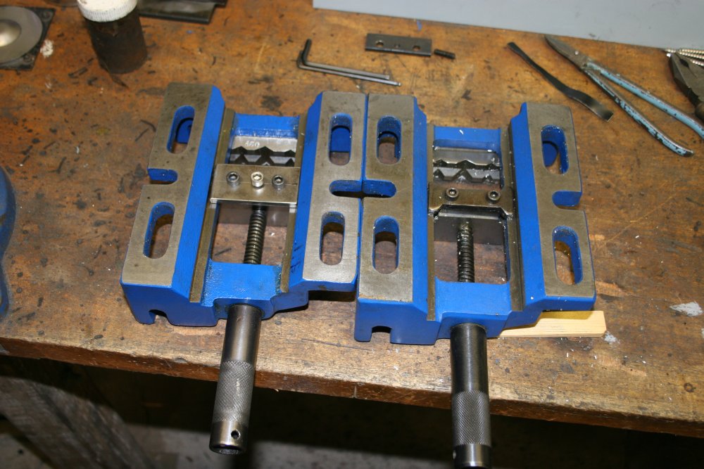
Hmm... I have two vices the same, so I looked under the other one. Wait, they are not the same! There are many subtle differences. Mainly, on the 2nd one the cross piece is done right, so it doesn't jam. Apparently the jammed one is made in a different Chinese factory than the other. Sigh. OK, so I have to make a workable cross piece for this 'cheaper copy' of a cheap Chinese machine vice. Pic 4 is with the new cross-piece in place (on the left vice.) A small shim fixed the height mismatch problem.
Then back to making the jig. The first thing was to add stops and clamps so the stainless disks could be repeatably positioned. And no, when doing something like this I don't care about neatness. It just has to work.
 |
 |
 |
 |
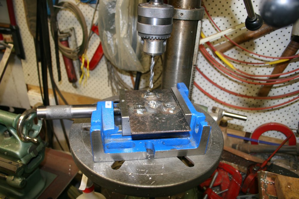 |
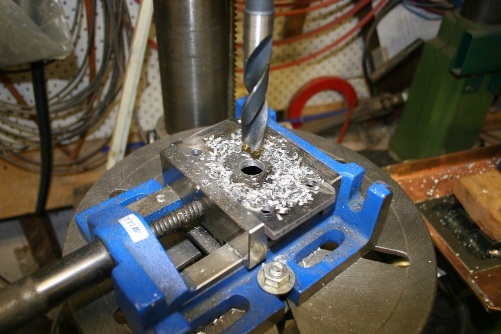
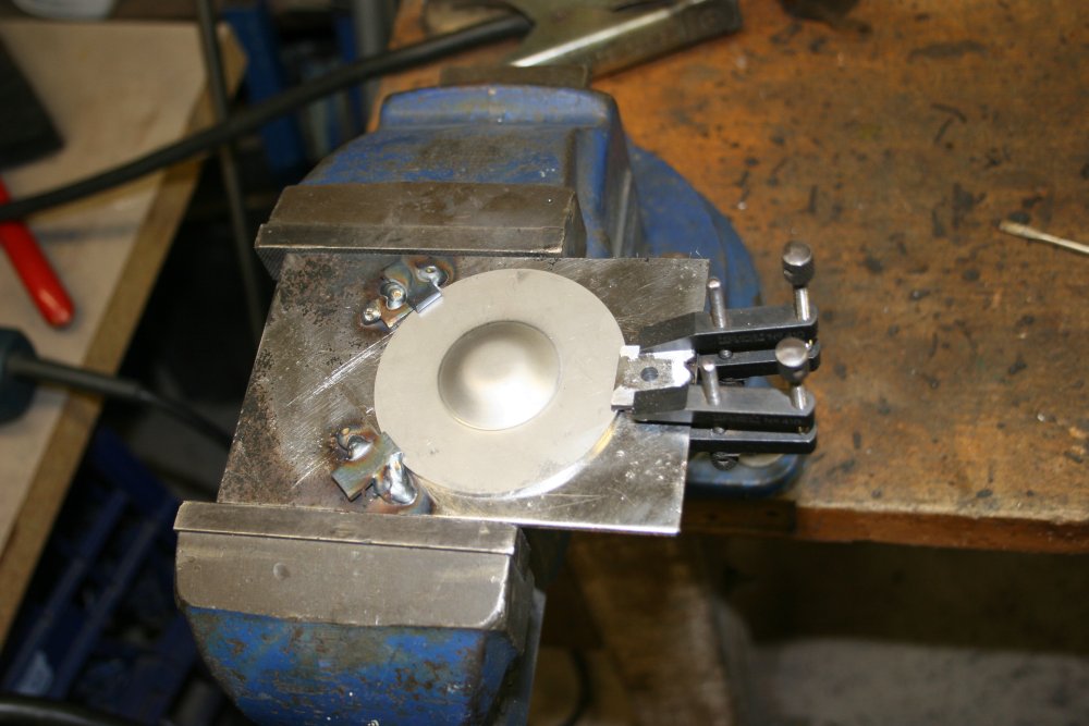
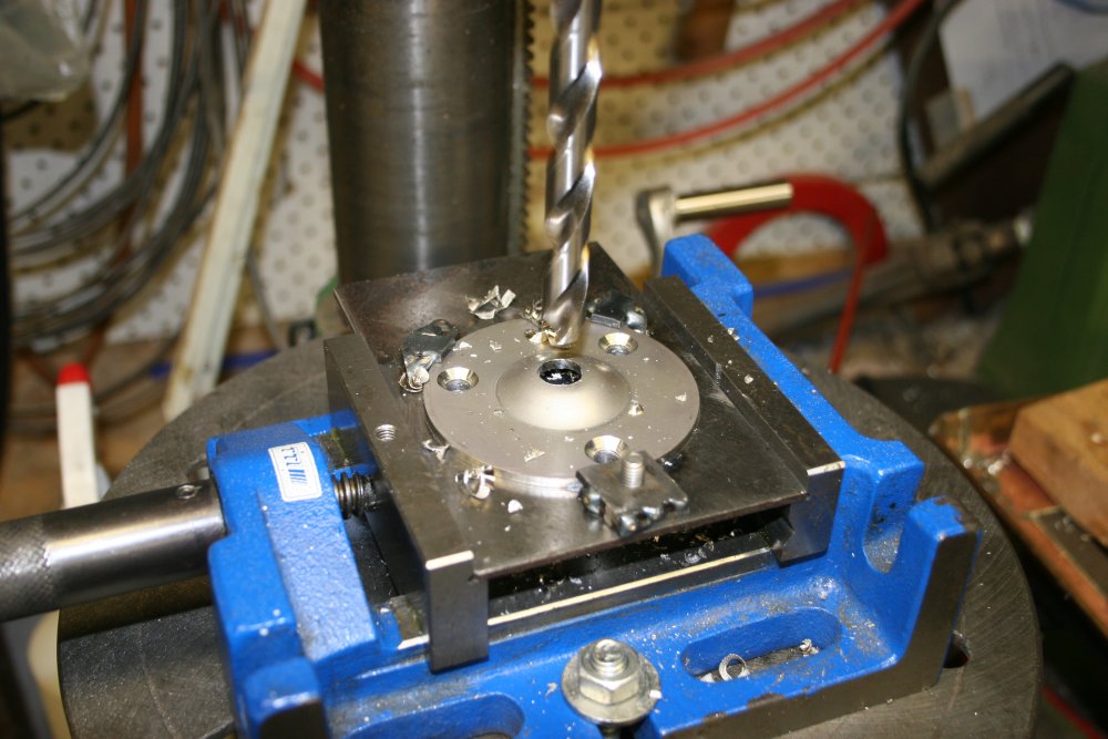
That's the disk clamping done. Then the disk outline is scribed, allowing layout scribed lines and center punching for the holes. Since the sheet is only 3mm thick, and I'll be drilling eight of the disks, the guide holes needed a bit more solidity. So I welded some backing pieces on and drilled through them too. Finally, in the last pic, the repaired vice is holding the finished jig with a stainless steel disk being drilled.
Stainless steel is a little tricky to drill. These alloys 'work harden' as they are deformed or heated. If the drill bit cutting edges are allowed to repeatedly pass under pressure over the same surface of the stainless steel, the stainless steel hardens, becoming nearly as tough as the drill bit metal. Once that happens, suddenly a lot more heat is generated by the metal to metal friction, and everything heats up rapidly. This destroys the temper of the drill bit metal, making it softer. Then you have a hot, soft drill bit, rubbing against hot, hard stainless steel. And that's the end of the attempt to drill a hole.
The right way to do it, is to ensure the drill bit is sharp (less distributed friction), run the drill at a medium-low speed, (less friction heat), and drill the hole with strong continuous pressure, so the drill bit is always cutting a slice of metal off. Thus the cutting edge never touches metal that has already been work hardened. The drill chips are hard, and tend to jam the drill bit in the hole if they build up. And by 'jam', I mean really lock the drill bit suddenly, possibly snapping it off. You can hear if this is about to happen, as it starts making little popping sounds. At the first sign of this, quickly withdraw the bit to clear the chips, going from full pressure to removing it suddenly so there's virtually no time when you're only pressing lightly. Pressing lightly is bad — it can lead to that hard-hot and ruined drill bit failure mode. Likewise when restarting to drill, begin immediately with strong pressure.
One last thing to bear in mind when drilling stainless, is that the drill swarf strands are extremely tough, and razor sharp. With mild steel it's generally OK to ignore the swarf brushing against your fingers. Not with stainless. Wear thick leather gloves, or keep hands well away. Those little swarf strands whizzing around the spinning drill bit can do serious damage. Think flying razor wire.
 |
 |
 |
 |
 |
Drilled. Then there's the countersinking to do, to match the shape of the screw heads. For this I reground the point of a large drill bit, to the 45 degree countersink angle. An ordinary countersinking bit, as for woodwork, could not possibly deal with stainless steel. Only something that takes a clean cut with each pass can work. With only two cutting edges a drill bit for countersinking has to be ground to a shape very close to conical, otherwise it will wobble around in the hole it's making. The result is a non-round hole, often more like a triangular hole.
This attempt worked well enough. I did one countersink hole by eye, checking the fit with a screw as it got close to right. Then set the drill press depth stop to do all the others the same.
Ha ha... Or I thought I did. You can see in the last pic that somehow I missed doing one of the disks. Blind. Didn't discover this till later, by which time the drill press setup had been changed. Sigh... set it up again...
 |
 |
Now for the curved metal bars to support the railings. First thing is to decide what shape I want it. How far out from the wall should the railing be, and how high above the mounting plates?
I cut a short piece of the railing tube off the stock, to use as a layout puppet. While hand filing the edges smooth, drew first blood on this job. A small cut, where I pinched skin between the tube end and the file. Trivial injuries are the best kind, since I'm apparently too stupid, clumsy and careless to avoid any at all.
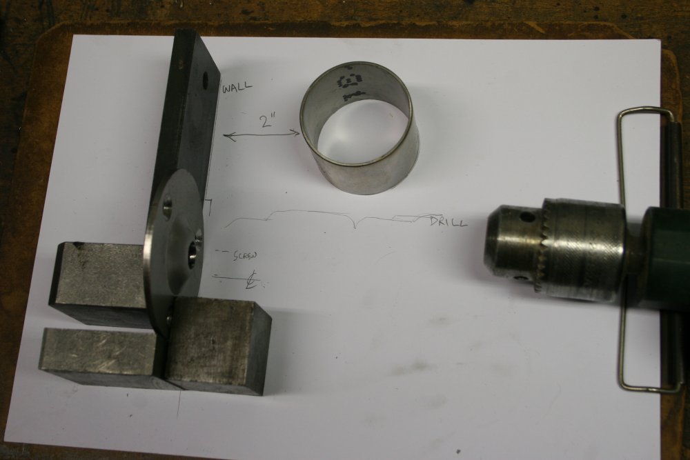
One thing I want to be sure of, is to not end up with a construction where the drill can't access the screws. So that sets the minimum height of the railing above the wall plates. Also I'd guessed a two inch gap between the wall and the railing would look about right, and a web search confirmed that meets the relevent Australian standard.
 |
 |
 |
 |
 |
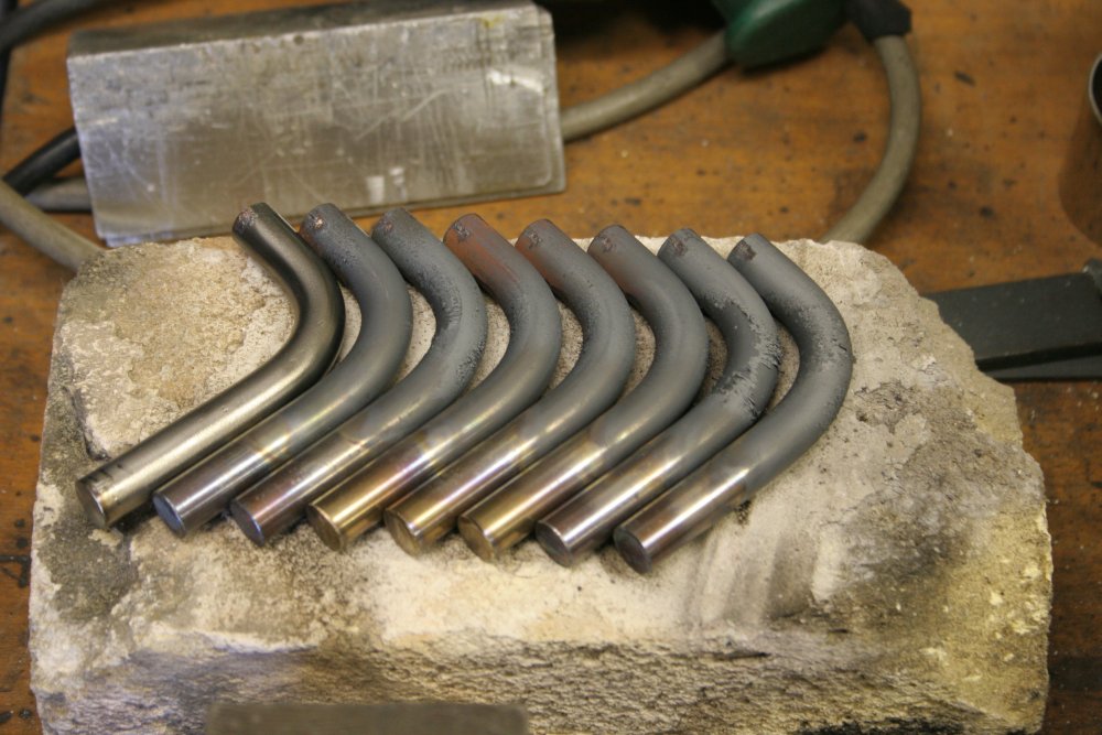
Now I know what shape I want the support bar to be, how to bend it? More to the point, how to bend eight of them the same?
Obviously, they'll need to be red hot while bending. Also the bar will be much easier to cut to identical lengths before bending the pieces. So I'll be bending red-hot short pieces of bar.
This implies several things:
- The bending operation must be done very quickly, since this 12mm thick stainless steel bar won't stay red hot for long once it's out of the flame.
- The jig will have to be something that can take the heat.
- Same for whatever I use to hold the end of the bar to apply the bending force.
- To ensure the bent bars are all the same, one end has to be clamped in a uniform position during the bending.
- And that clamp has to be precise, and quick to apply, to not waste time. Strike while the iron is hot, etc.
- Also, the heating of the bars has to be fairly similar for all bars. In the intended bend area, but not so much the two ends.
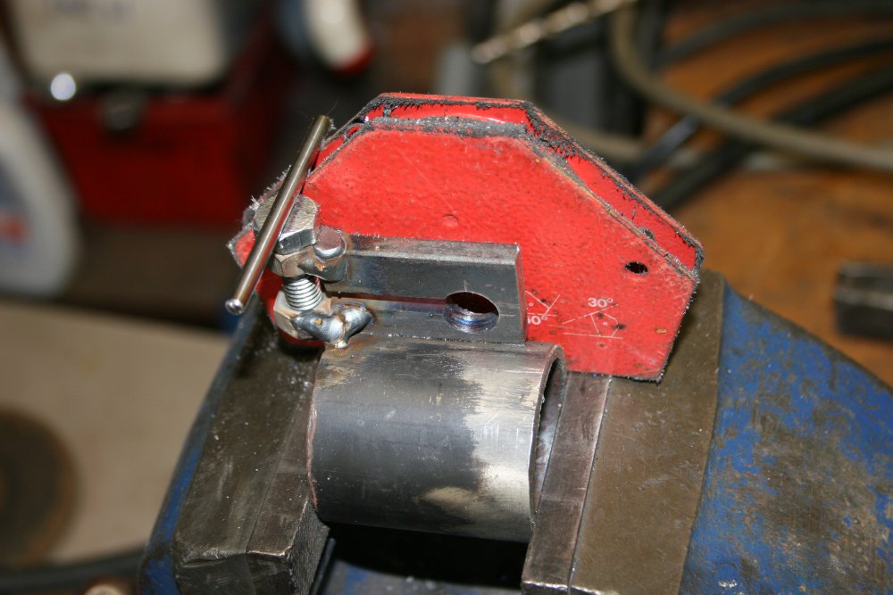
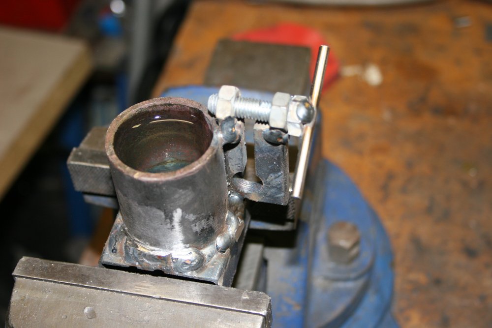
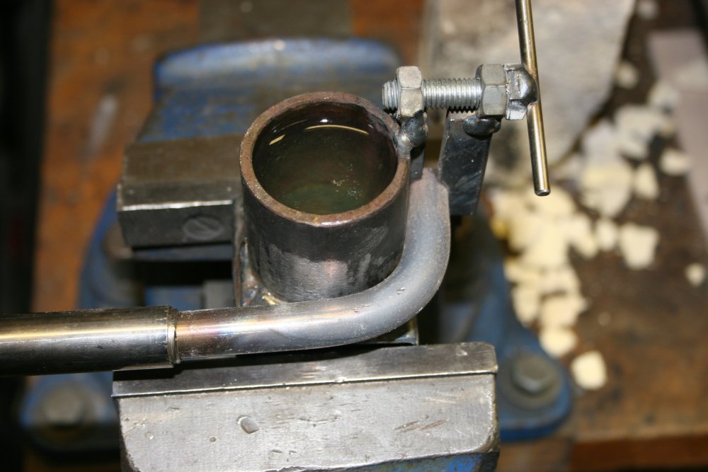
A piece of heavy walled steel tube with the right radius turned up in my scrap pile. The 'clamp' is a piece of flat bar, drilled and slotted so the hole can clamp tightly on the rod end. The clamp bar is welded to the tube piece, using the actual round bar as a positioning guide. A pair of M8 nuts are welded on the end of the clamp, then the outer one drilled out to 8mm, and a bolt with a cross piece welded on its head completes the clamp. Not shown, is that while welding the nuts I had a strip of thin sheet metal wrapped around the bolt, to protect the threads from welding spatter.
Finally the tube end is welded to a bit of rectangular hollow bar, to serve as a base to clamp in the vice. After doing the initial welds there, I realised "Oh hey, I could fill the tube up with water to keep it cool." So then I tried to complete a water-tight weld around the base of the tube, and stuffed it up somewhat. First attempt leaked in several places. On the third attempt it held water.
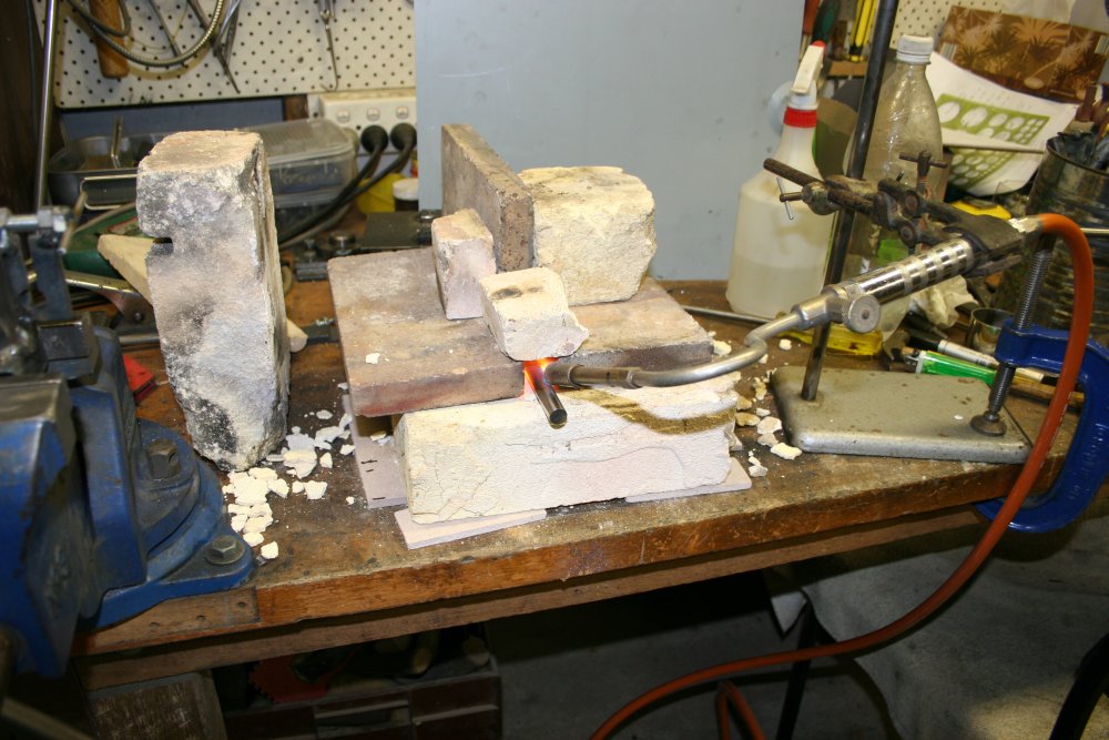
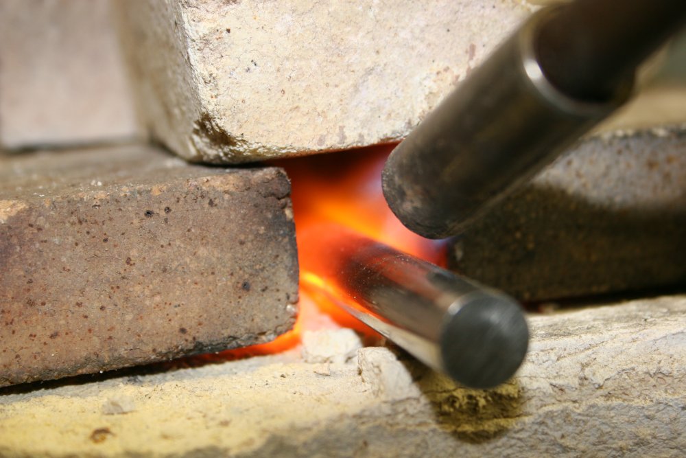
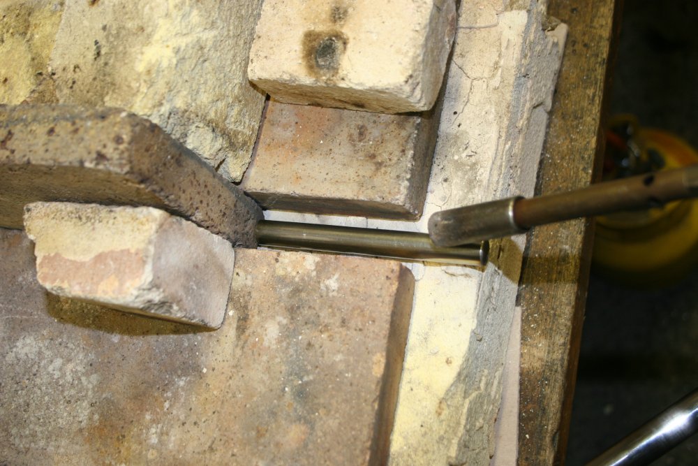
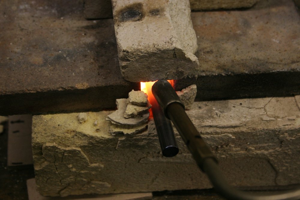
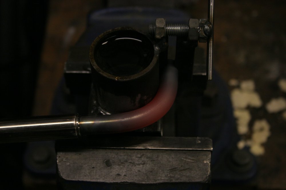
Then a quick improvisation of a mini-furnace, with a guess of how much of the bar should sit inside, to leave enough cool metal at one end to grip it.
 |
 |
 |
 |
To pick up the red-hot bar, position it in the jig, then bend it, I'd found a long hollow polished steel printer rail in my box of bars from printers, photocopiers and such. The inside diameter was a little smaller than the 12mm stainless rod, but that was easily fixed in the lathe. I only drilled it out to about an inch depth, so the rod sits on the internal lip. I need to be able to press the hot stainless bar into the clamping hole.
So that worked. I'd cut the rod a bit longer than I thought it needed to be, since it's hard to estimate what the resulting size will be after bending. With it bent I measured the amount that needed cutting off the end. Subtracting that from the original length gives the length I need to cut the other seven.
 |
 |
 |
 |
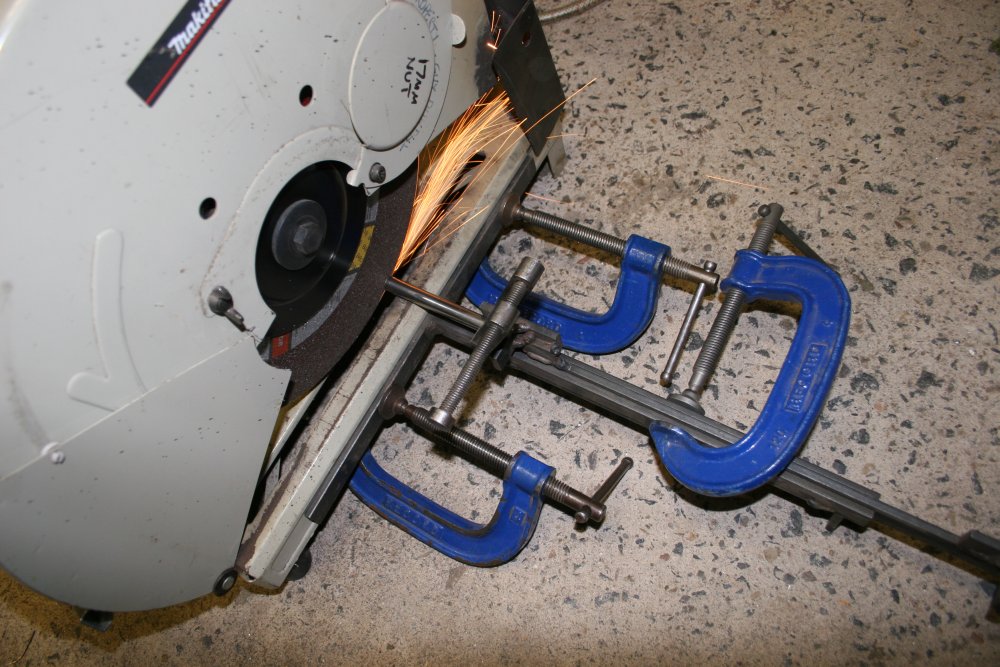
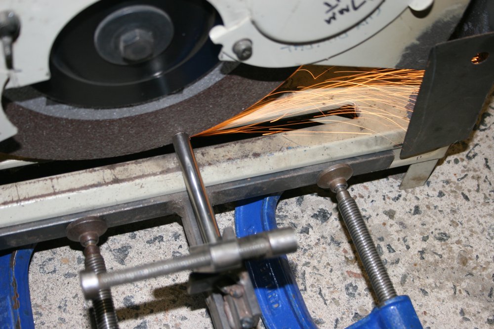
 |
Using an end-stop on the abrasive cutter, so they are all exactly the same. With the piece being cut having its end against a stop, it's important to clamp it. Otherwise as the cut completes, the now free piece of metal will rotate, making itself effectively longer - between the end stop and the cutting disk. The result can be bad.
With them all cut, it's time to fire up the miniature furnace again.
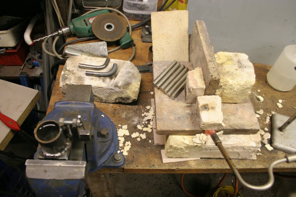 |
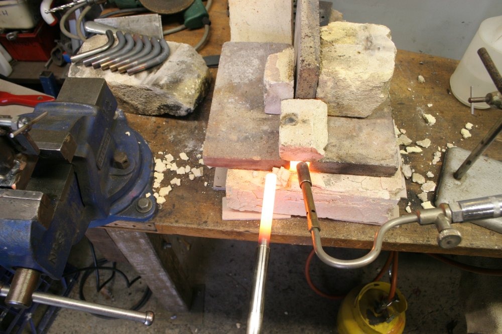 |
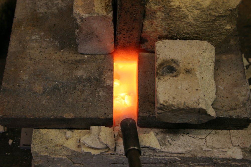 |
 |
 |
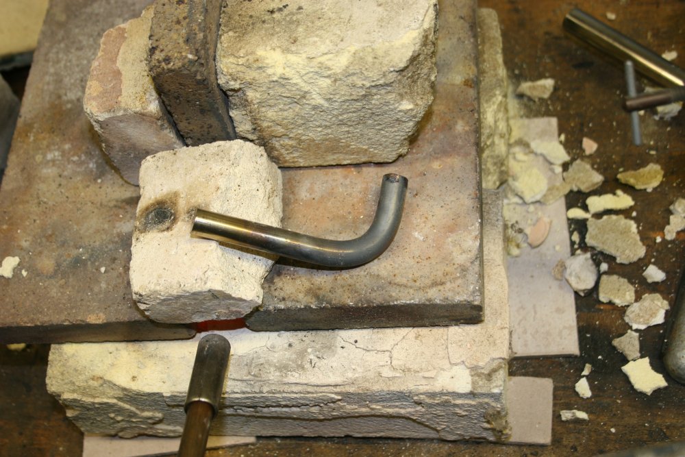
The second one, that was cut to the right length then bent checks out — it matches the first one. So the rest of them can be done quickly. Ha ha... the clamping screw lever on that jig is not far from the bright red hot bar when tightening it up in a hurry by hand. Slightly nerve wracking. Anyway, they all turned out OK.
Finally some wire brush cleaning to get the scale off, followed by some buffing.
 |
 |
 |
 |
 |
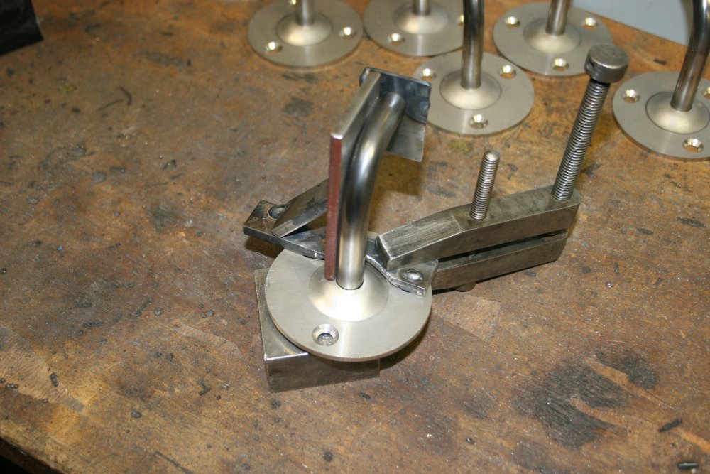
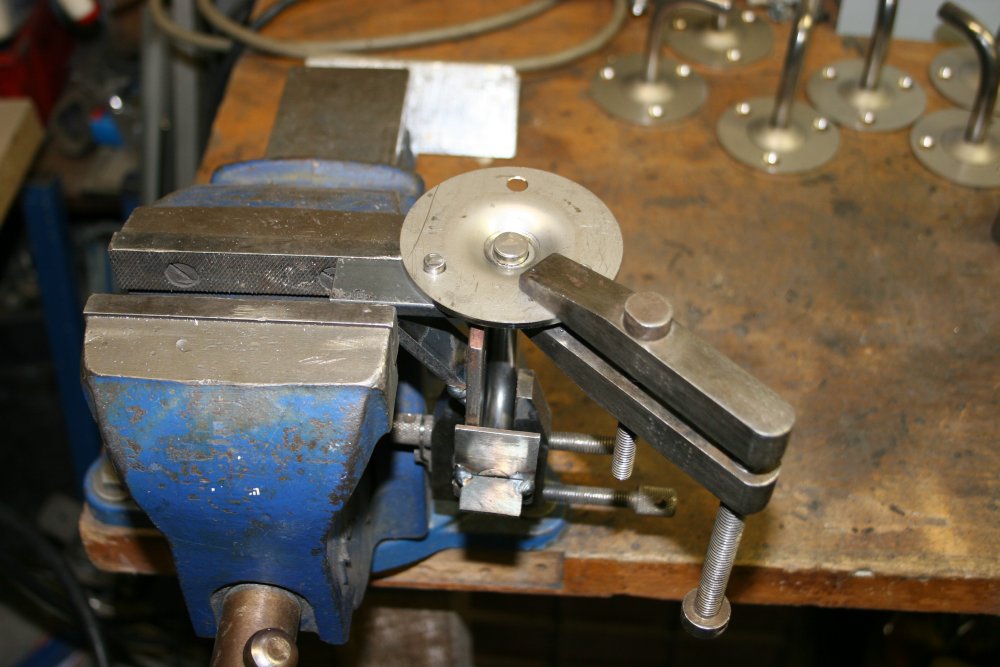
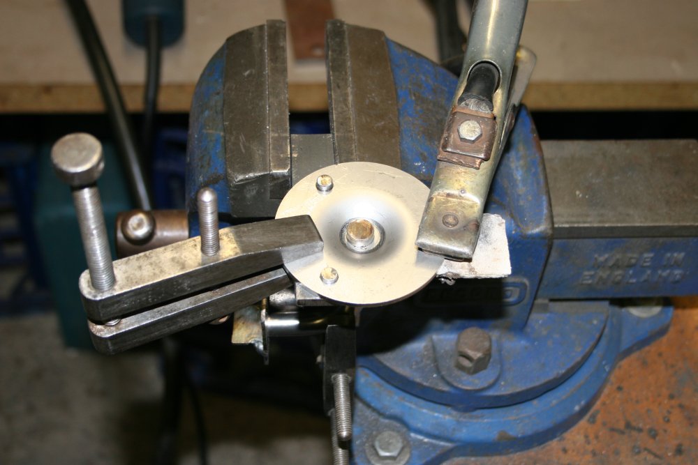
The next stage is to weld the disks to the elbows. To get them all the same, requires... you guessed it, another jig.
 |
 |
 |
 |
 |
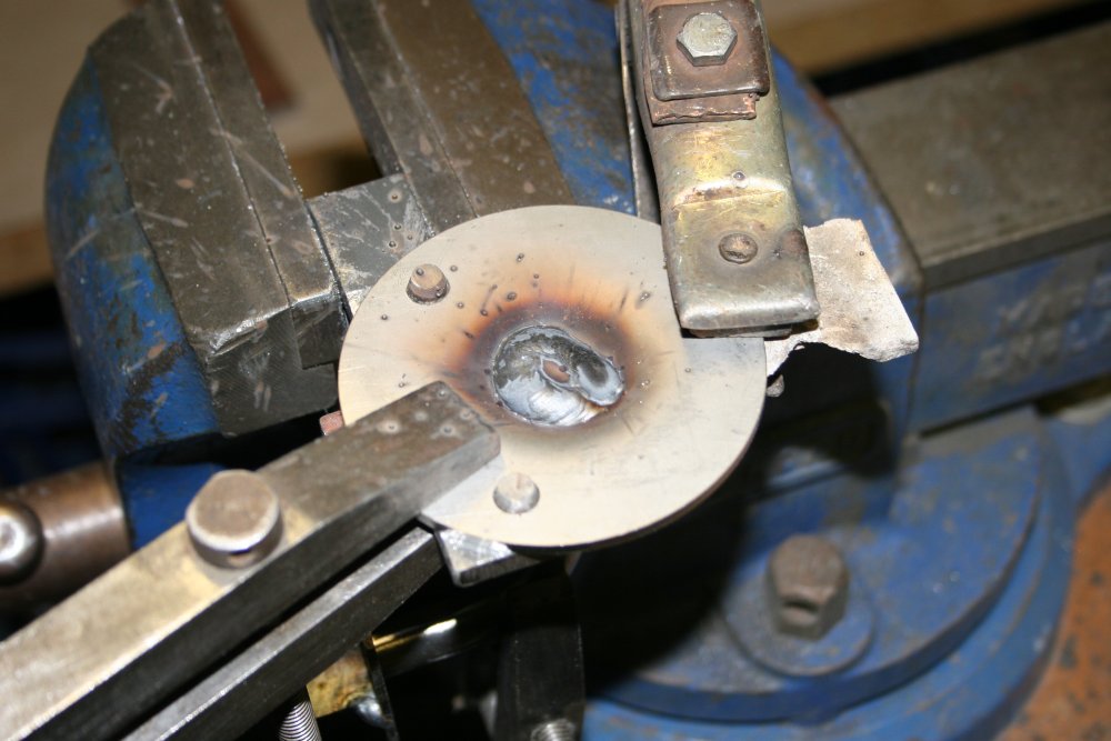
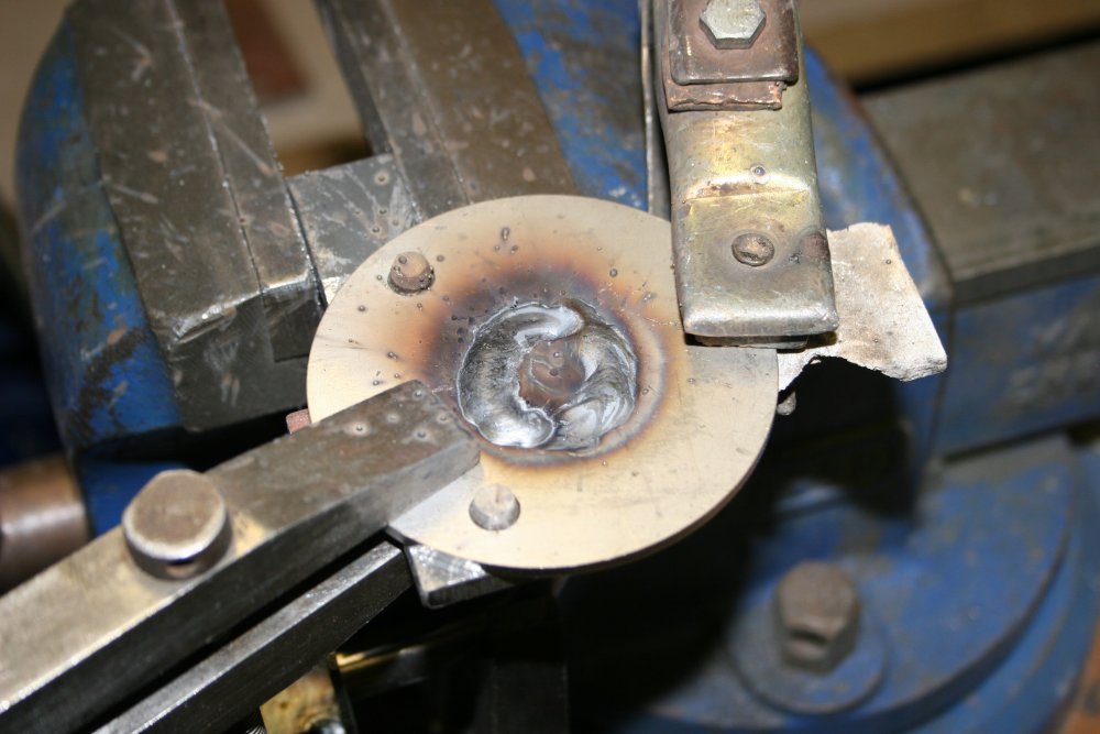
Then on to the welding. Changing the wire roll in the MIG welder is a pain, but has to be done. I swapped the steel wire roll with the roll of stainless wire, made a guess at the best current setting and feed rate on the welder, then tried the first one.
That probably sounds easy, but actually this was a moment I'd been dreading. To properly melt into the end of the thick stainless rod I knew the welder power had to be set fairly high. It doesn't have quantified Amps values on the dials, just numbers one to ten. I set it to 6, which is high for 0.8mm wire. The worry was I didn't really know how much chance there was of burning through the 3mm disks with the weld metal pool. When there's a large difference in thickness of two parts (12 mm rod vs 3 mm plate) it's easy to melt through the thin one while welding the thicker one. You'll notice I didn't buy/make spare disks and elbows. This was more a case of 'pray' rather than confidence in my ability to guess right.
The technique is to play the arc mostly on the thick piece, and weave it to the thin one only enough to flow the weld pool onto the thin piece just enough to melt in, not enough to go right through. Having put a fair bit of work into these parts already, the feeling during the actual welding is a kind of terror. It has to done fast and the visibility through the visor is crap, so it's as close to winging it as can be.
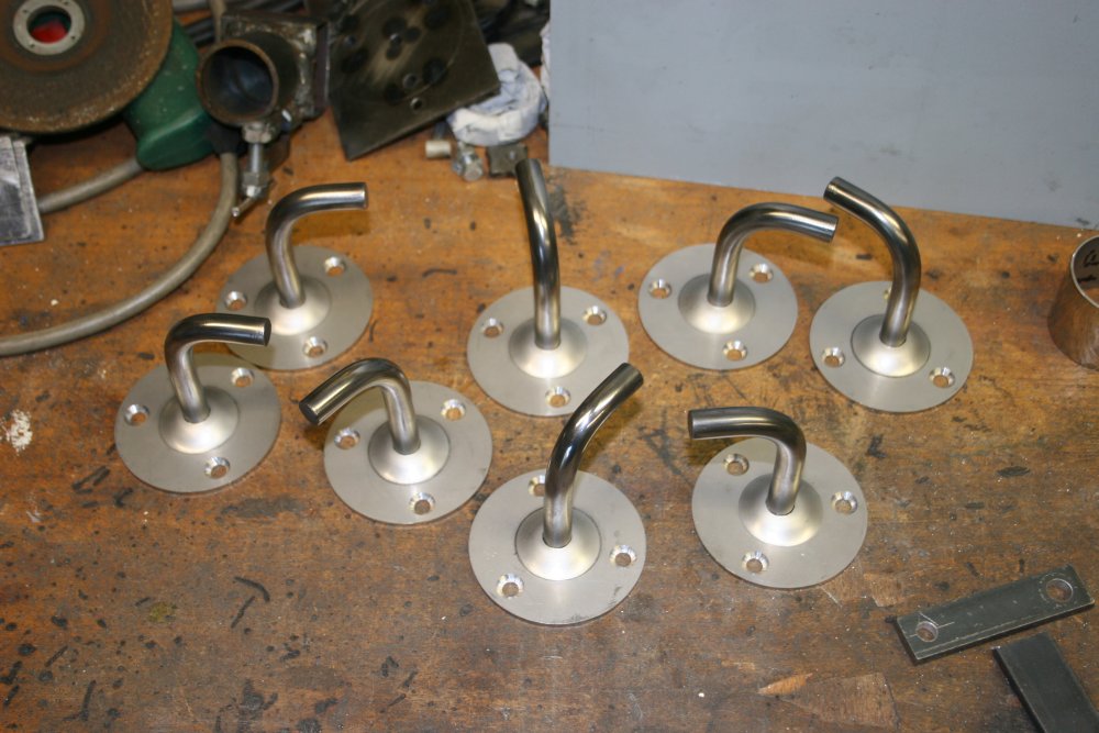
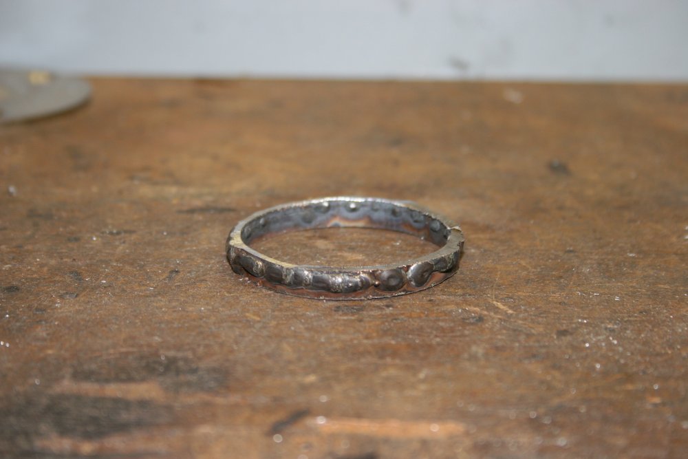
Anyway.... it worked. At least no melt-throughs. A couple ended up beading higher than the disk base plane, so need grinding back. Because of setting the current high, there's quite a bit of spatter adhesion. But that's easily ground off too.
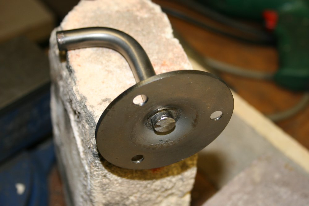
Something I didn't anticipate was that heating the center like this resulted in a noticable warp on most of the disks. With a pair of soft jaws in the bench vice and some careful hammering, it only took a few minutes to have them all straightened out again.
 |
 |
 |
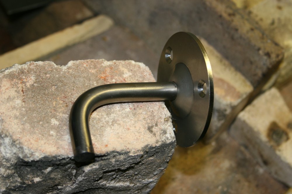
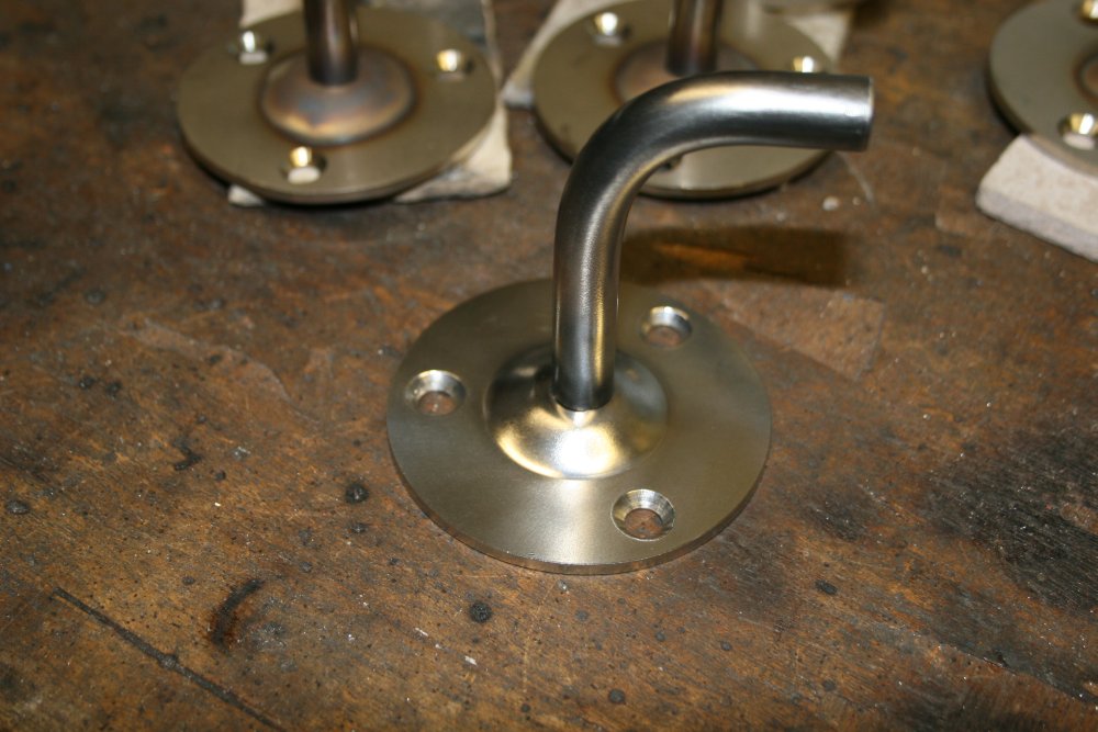
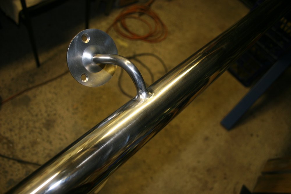
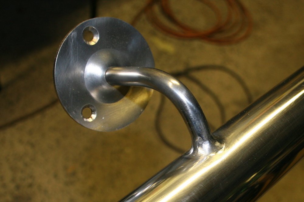
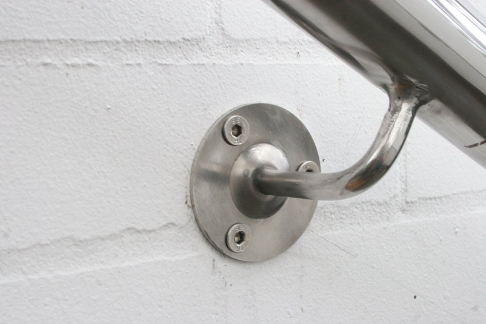
Polished up, it looks as good as a bought one.
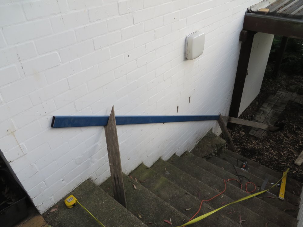
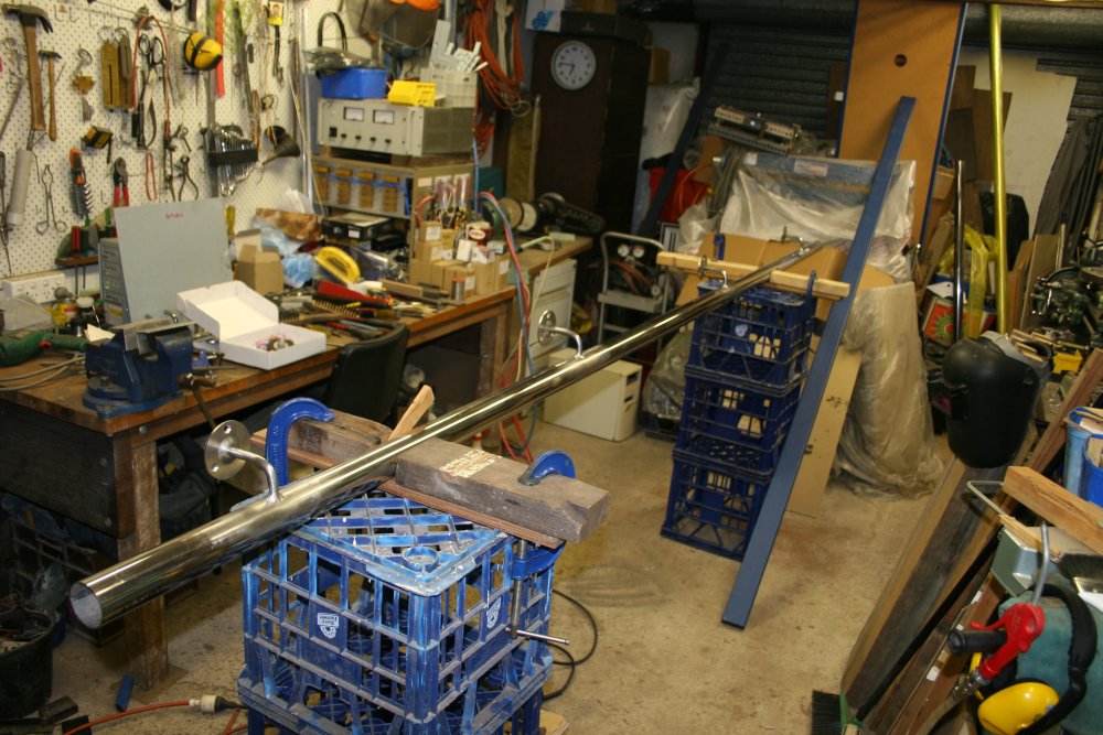
Next day was a trip there to mark up final positioning. Using a long steel beam as a straightedge on the stair walls, I'd worked out positions for the brackets so the screw holes didn't fall on or near any brick edges. Mortar is softer than the bricks, so it's not possible to drill a hole at the brick edge - the drill will drift off center into the mortar. I'd also noted cases where the brickwork was out of flat enough to require offsetting the height of the mounting disks. Most were OK in a plane, but a few had to be set a bit lower.
 |
 |
 |
 |
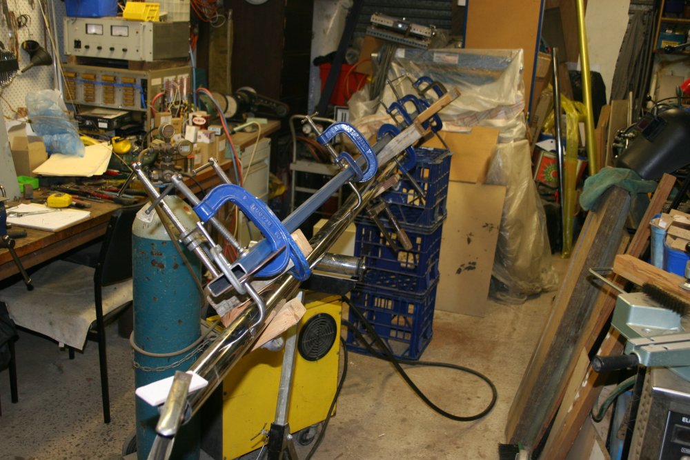 |
Now for the welding. The task was to rigidly mount the brackets against the stainless tube, according to the measurements I'd taken. Unfortunately it was too windy outside for welding stainless steel, and my workshop central floor space was occupied with a pile of stuff that had been there far too long. So there was a sidetrack involving moving stuff elsewhere.
With the floor finally clear, I used the same long steel beam I'd used as a straightedge, this time as a reference plane for the brackets. Then once it was set up, it took me a while to gather confidence to actually try doing the welds. My welding skills are rubbish, I know it. I'm entirely self-taught; never even had the benefit of criticism from someone who knows what they are doing. I don't know any professional welders, or even anyone else who welds regularly.
Faced with the prospect of potentially wrecking some very nice (and expensive) stainless tube, I chickened out for a while. Then there was a day of drama related to a large package coming from overseas. Finally it arrived OK, and the item was everything I'd hoped. With that boost, I hoed into the welding. Heh... starting with rigging up a small test piece, using short scraps of the same tubing and rod. That worked, so I did the first actual railing weld. Well, half of it, since I couldn't get at the other half in that position.
On inspection, the weld was OK (if a bit rough) but there were a lot of spatter adhesions spread around on the nice shiny tubing. Even several cm from the weld. That's one problem with stainless - it has such low heat conductivity, that molten spatters melt into the surface very solidly. Yes, I know, excess spatter means the weld current is too high. But I needed it high in order to be sure the bead would cut into the thick stainless rod properly, and be able to steer the bead onto the thin tube in short pulses. At least that's the theory.
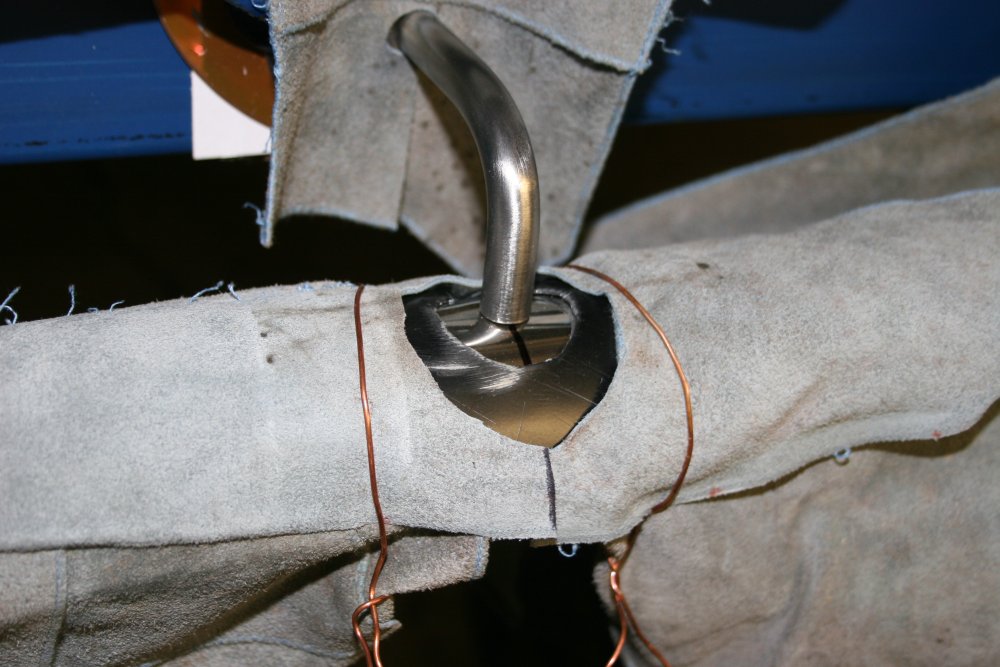
So to cut down the damage to the nearby tube surface (it makes more work polishing!) I made a rough stencil of a piece of copper foil, and also used some leather gloves to cover the tube beyond the stencil. Then proceeded on to do the 'top side' welds on the other brackets. Then rotated the whole thing round and did the other sides of the welds.
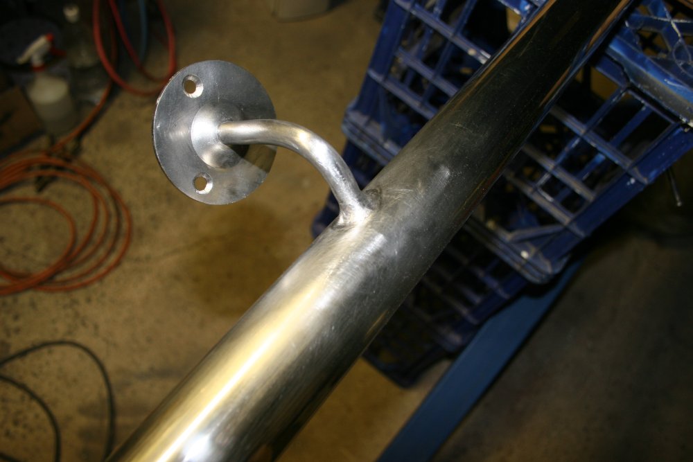
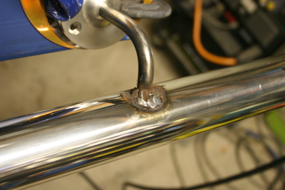
After removing all the clamping, the nastiness of my welding really stands out. I imagine someone skilled at this would be able to achieve nice neat weld fillets that didn't need any more work than descaling and polishing. Not so mine. What's needed with them is a more or less total re-profiling with a grinder. Which of course provides plenty more opportunity to mess up the job fairly badly.
 |
 |
 |
 |
 |
After gritting my teeth and getting through the grinding tedium, it's starting to look not too bad. Then there's the hand filing with a big round file to remove the worst of the grinding disk cut planes, then the hand sanding with emery paper, then the power buffing with a calico wheel and polishing compound. Pics 3 and 4 are the more or less final result.
So that's one railing done. As expected the welds along one side of the tube have resulted in the tube being very slightly bent at those points. As the weld cools it contracts. I'm not sure how to reverse this slight bend effect on such large diameter tubing. Heating the entire tube to red heat at the weld vicinity, and forcing it straight using a jig and jack? Maybe... But it's a very slight bend, and some forcing of the mountings should be enough to make it look straight. So I'll leave it.
The end caps are a press fit. I debated whether to tack weld them in place, but decided it would be better to leave them off for now, then glue them in with silicone glue once the railing is mounted in place.
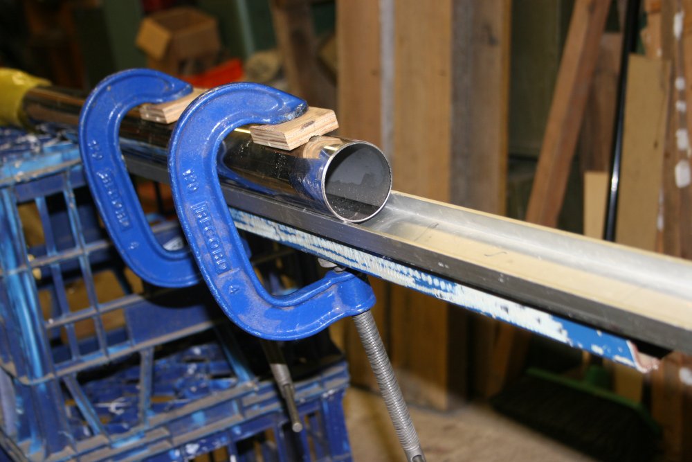
The next task is to join two sections of this tube together neatly, for the other railing. At the supplier the tube comes in 6 meter lengths. They only had one full length plus an offcut. This was actually good, since if I'd insisted on two 3.5 meter lengths I'd have been charged near the price of two 6 meter lengths, as that's what would have used up from the supplier's point of view. As it was I got one 3.5 meter length cut from 6 meters, the 2.5 meter remainder, and an longish offcut at a good discount since it was effectively scrap to them.
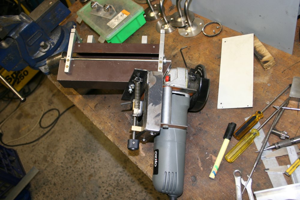
But now I have to join the pieces. I can do this, since the last time (first time!) I did some stainless railings I'd made a rotating pipe welder, and a gadget for precision grinding the pipe welds flat. This time is only different in that the pipe is much longer, and larger diameter.
So the first task is to make a couple of roller bearing pipe supports, to take the weight off the pipe ends so my rotating pipe welder can handle this. The last pic above is cutting some pegs to mount the roller bearings.
 |
 |
 |
 |
 |
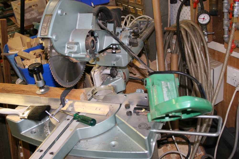
Then of course when I tried to use the drop saw to cut the two aluminium brackets for the roller bearings, the saw's main bearing immediately semi-siezed. How ironic. Fortunately a quick disassembly, cleaning the bearing in kerosene, and reassembly fixed that problem. The rest of the roller bearing construction went quickly, and there they are.
 |
 |
 |
 |
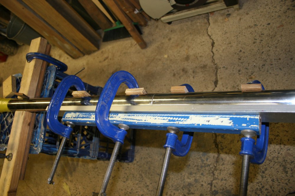 |
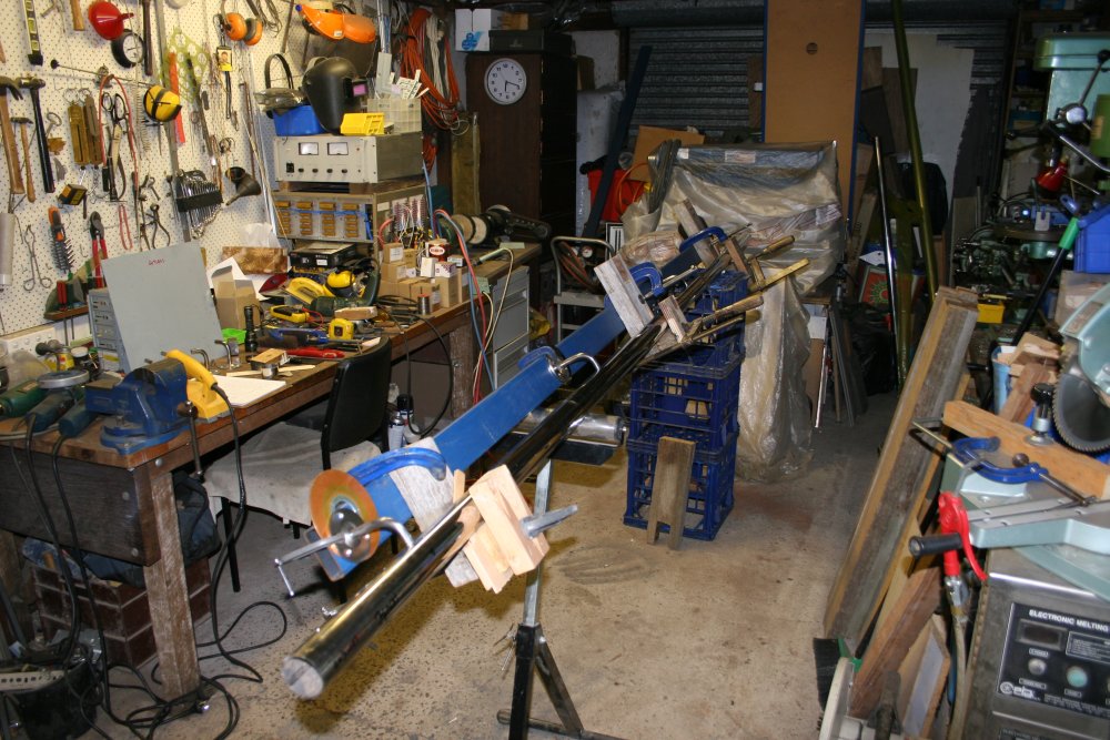
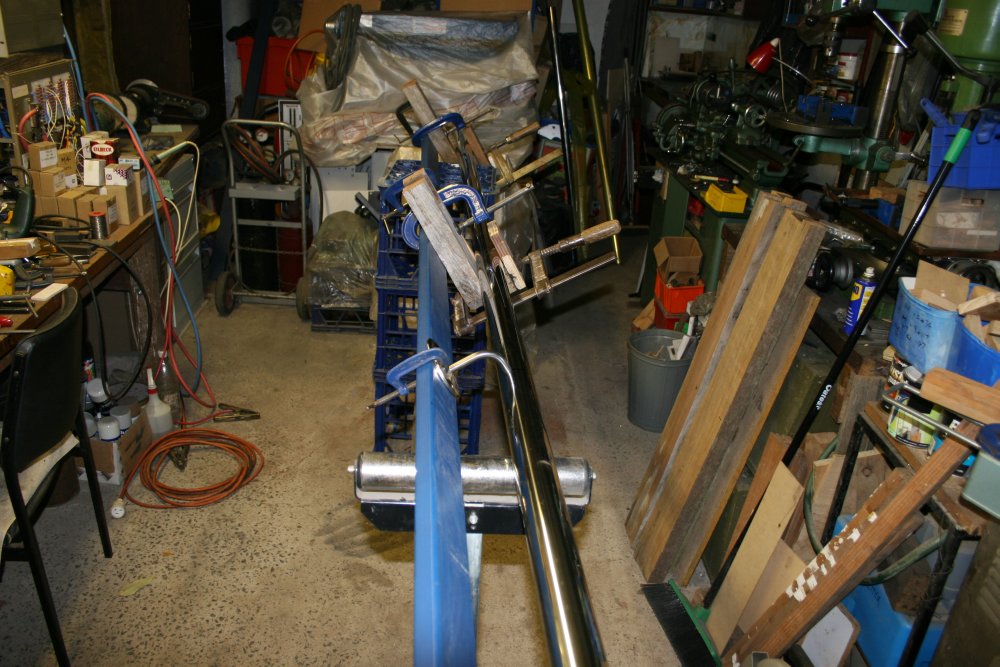
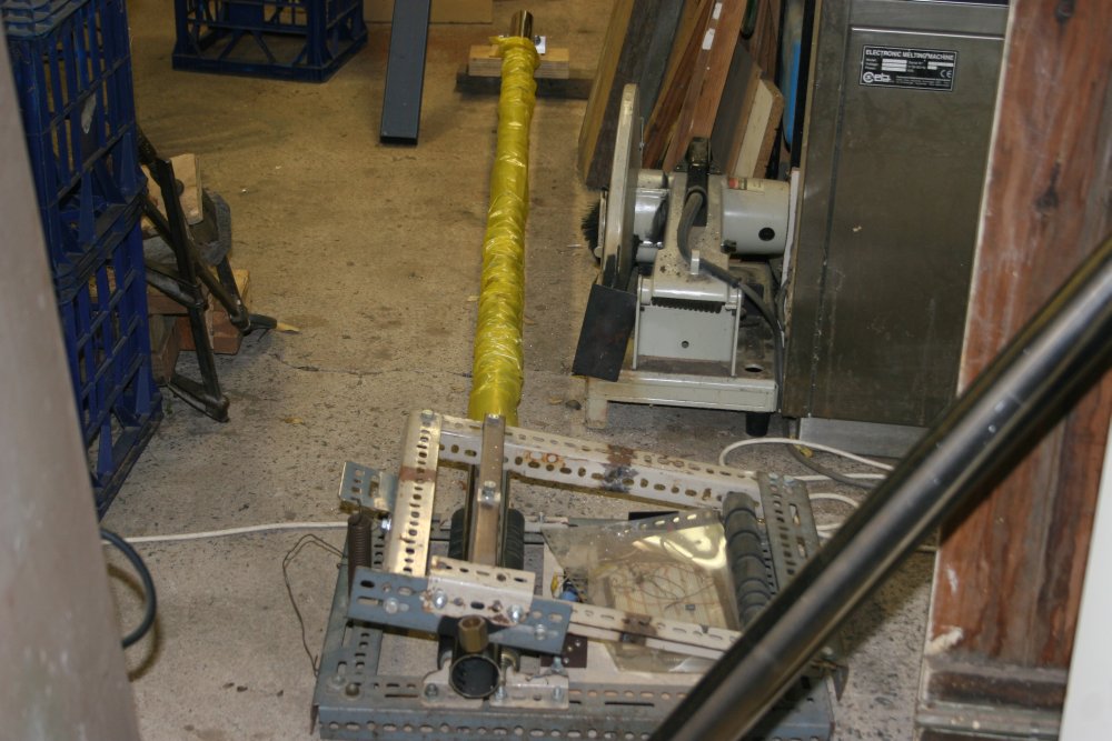
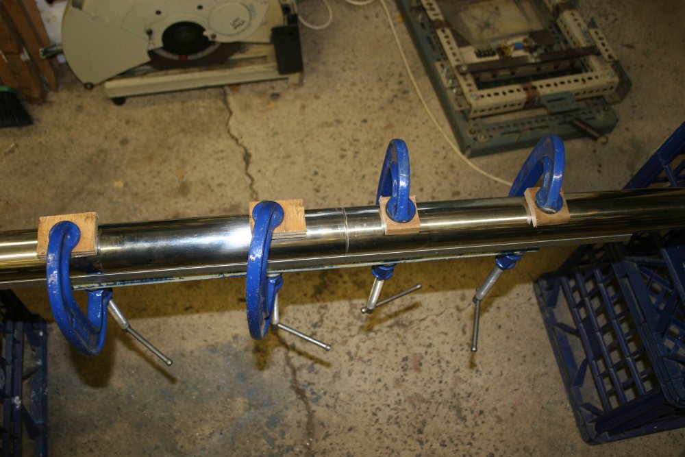
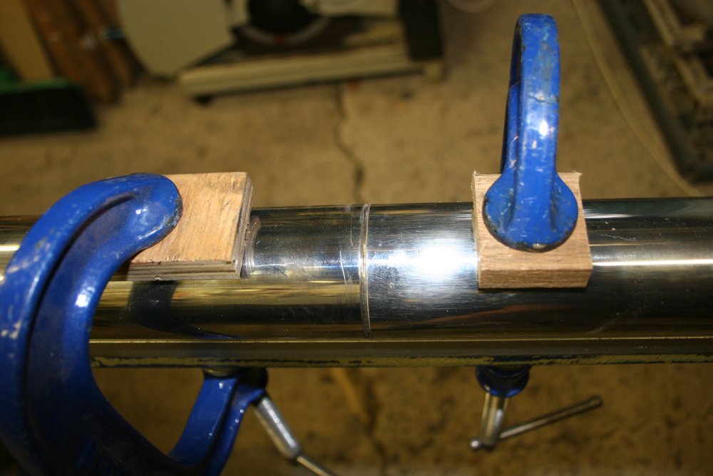
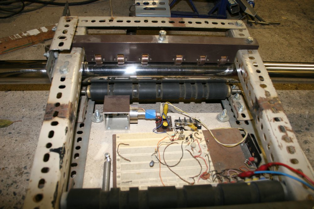
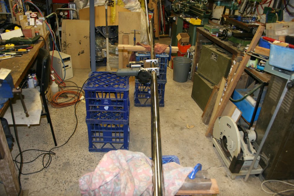
That... thing on the floor in pic 1 is the improvised pipe rotator, with the 2.5 meter section of tubing in it. This is just setting up to see if there's enough space. There is if I run the other piece of tubing through the doorway into my electronics workshop. I don't want to cut the short one to get the right total length yet, since if the join weld doesn't work out I want to be able to cut it out and try again.
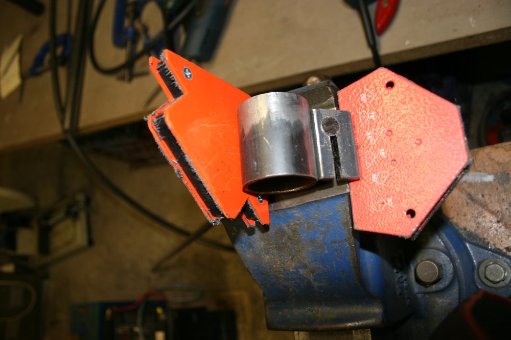
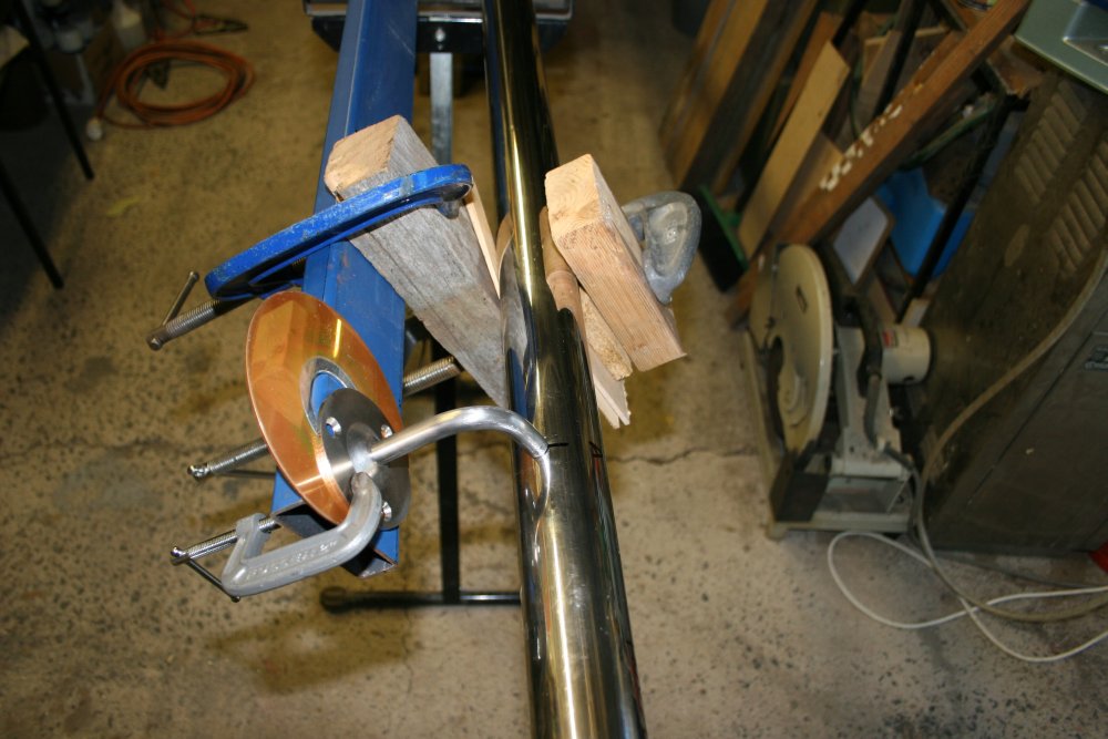
Then there's the issue of making tack welds on the join while holding the two pieces of tube exactly aligned axially. That turned out to be easier than expected, since a section of aluminium U channel I had was just the right size. Plus a bit of steel behind it for added stiffness.
 |
 |
 |
 |
 |
Over-optimistically (and because I knew I could easily undo it) I tried a manual weld around the seam. The weld itself was sound, but due to heating unevenness around the tube, the result was a non-straight join. I'd pretty much expected that. So cut out that weld to try again. The first pic is the cut-out ring with the weld around the middle.
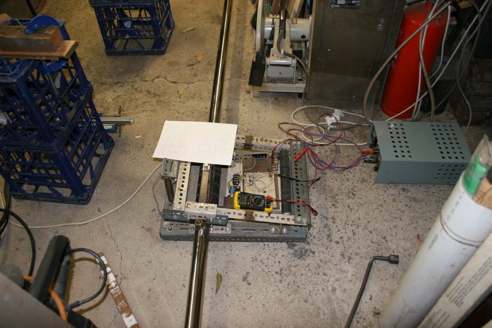
Repeating the tackweld setup, this time I wasn't tempted to try anything but three small tacks equally spaced around the tube. The result was straight, but obviously not very strong. Handling the long tube very carefully, I transferred it to the pipe rotator, and connected a power supply.
 Hah. My jury rigged circuit, that has been sitting on a prototyping plugboard for years because I've been too lazy to replace it with something more permanent, now doesn't work. A quick debug identified the jumper wire that had come loose, then it worked.
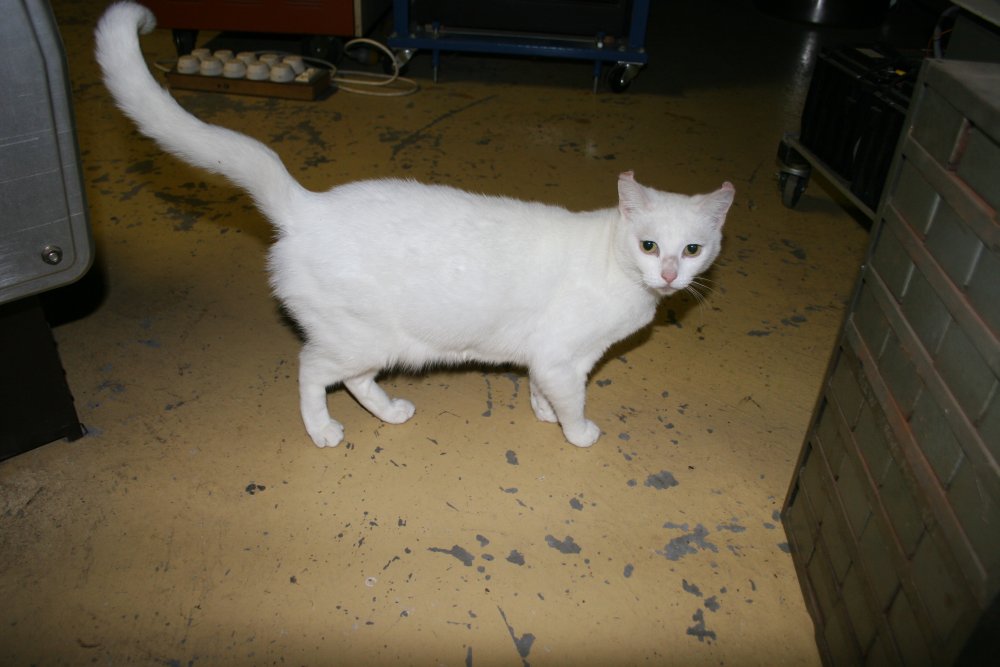
The weather's a lot warmer lately, so my cats rarely come inside to visit. Tonight Blanc was the representative sent in to enquire about when dinner would be served.
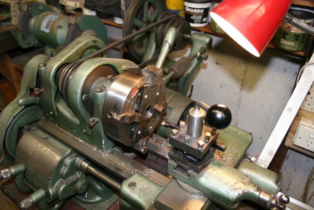
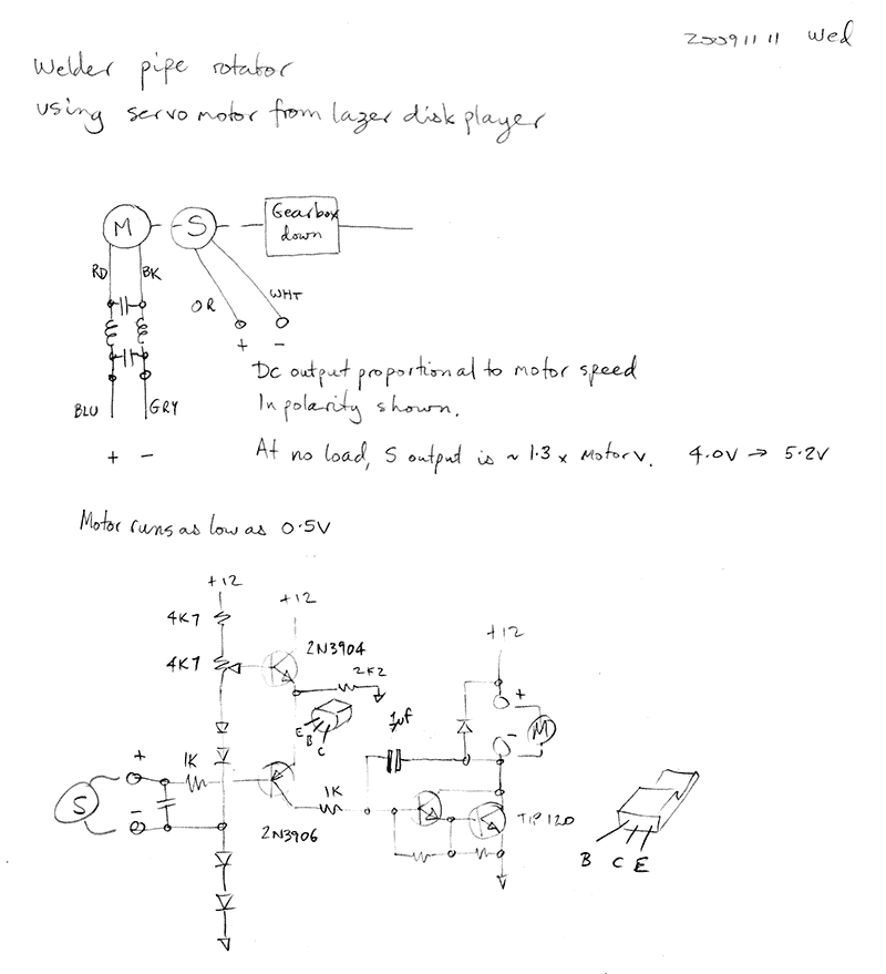
The rotator is primitive; it's another of those things knocked up in a hurry to do a job. But it does work. At left is the schematic I'd settled on when building it.
It looks cool with the welder operating; too bad while it's welding I have to closely watch it with my finger on the welder 'run' button, to stop it when the weld wraps around to its beginning. So couldn't take a photo.
 |
 |
 |
 |
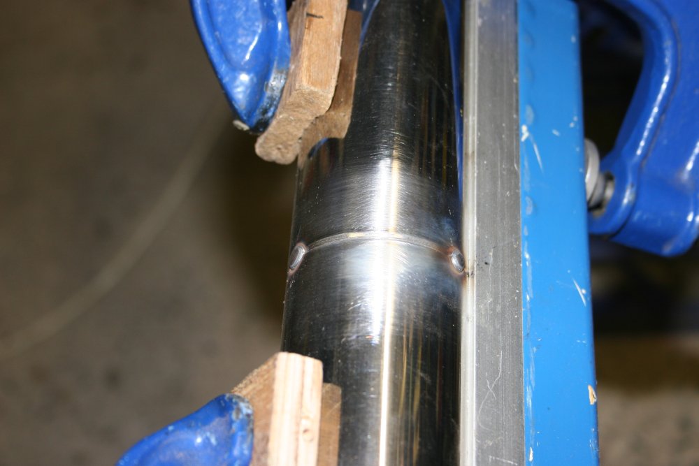
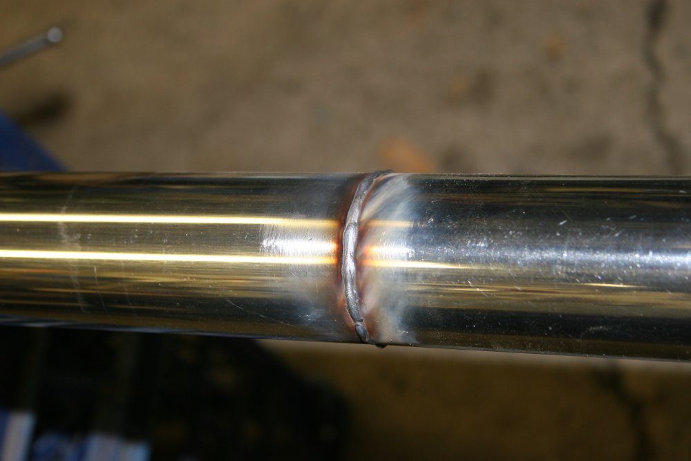
Success! I think I had the wire feed set a bit low, since I could hear the welder power fluctuating and the weld bead is a bit uneven. But that doesn't matter so long as it penetrated properly, Which I'm sure it did since the power settings were the same as for the manual weld, and I set the rotation (weld feed) rate slower than I'd been moving the torch by hand. The excess bead is going to get ground off anyway.
Much to my relief, the join is still nice and straight after cooling.
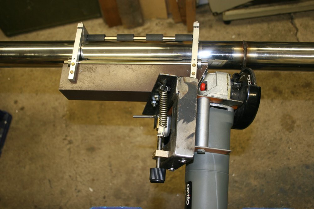
Years ago I made a precision pipe weld grinder, but unfortunately to suit a smaller pipe diameter than this railing. So the next chore is to modify it for the larger pipe.
 |
 |
 |
 |
 |
Which didn't take too long in itself, but there were some life dramas setting in at this point so there was a gap of several days. Anyway, my big box of rollers, rods and bush bearings salvaged from old printers came in useful yet again.
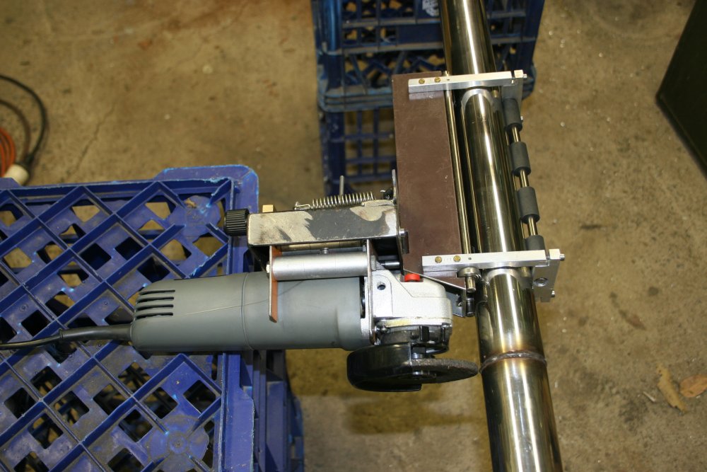
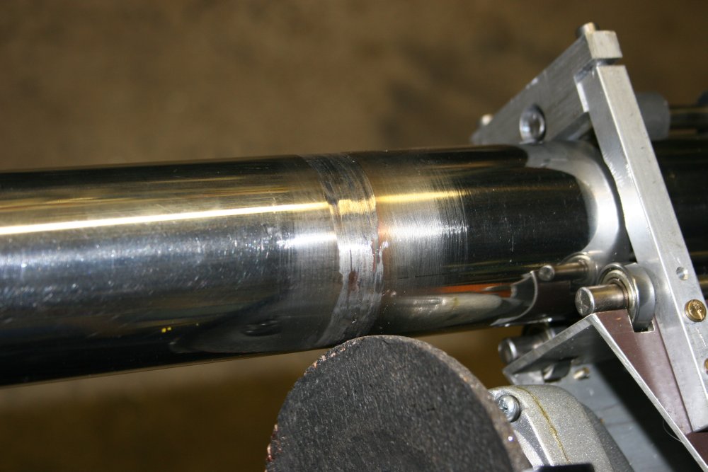
This jig allows the grinder wheel to be set precisely relative to the pipe surface. The pipe is rotated by hand, while the grinder is set gradually lower. Ideally the result is a perfectly even surface, and it's usually possible to get very close. The worst imperfection is that the jig rollers are not in the same line along the tube surface as the grinder contact point, so if the tube is out of round the grind profile doesn't quite match the tube surface. And tubes like this always are at least slightly out of round, so a final stage of hand touch-up with a fine flat file is necessary.
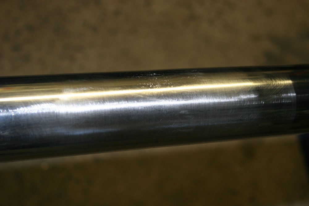
This time a few points on the weld were very slightly too low, with the result that I got too vigorous with the final filing touch-up. Thus leaving some scratches that couldn't be removed without taking off enough metal to make a noticable hollow in the pipe profile. Yep, my metal polishing skills suck as much as my welding abilities.
 |
 |
 |
 |
 |
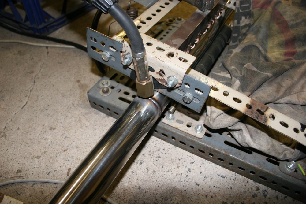
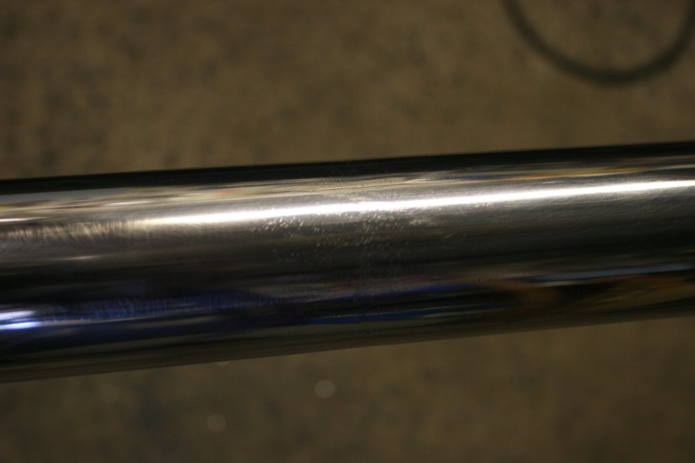
Still, it wasn't too bad, and polished up OK. So then this one's mounts were set up according to the measurements I'd taken, then welded. This time I used a better spatter shield, but was a bit clumsy with a couple of the welds. Which just made more work with the grinder, removing metal to get them back to a neat profile. I didn't bother taking pics of the whole grinding, filing and polishing tedium, since it's same as the first rail. Also 'life interruptions' were still active, so when I did get to work on the railing I prefered to just do it.
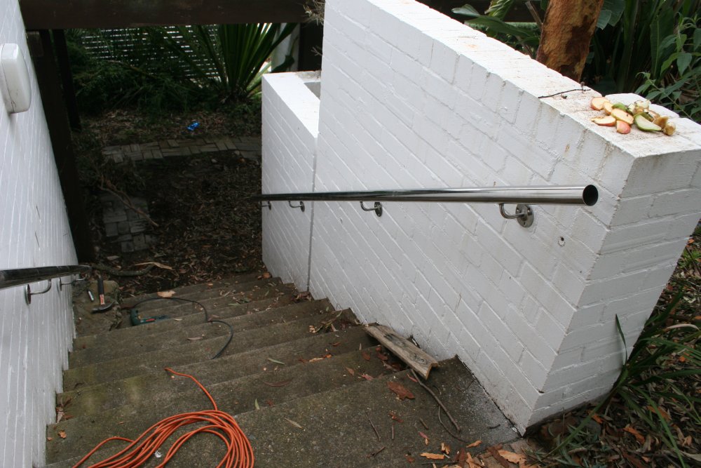
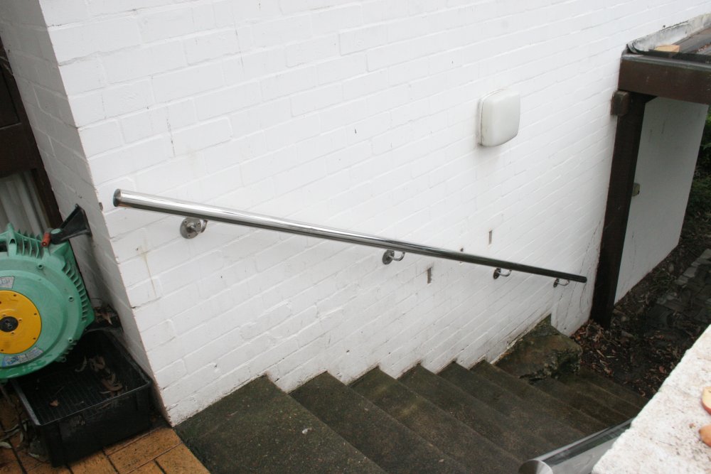
Finally on the 11th Nov the second rail was finished, and I took them round to my mum's and mounted them. The slices of fruit on top of the wall are put out by my mum for possums.
 |
 |
 |
 |
 |
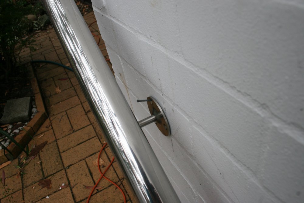
To mark the holes for drilling, I began with a single hole at one end, drilled it with a small rock drill, shoved a bit of stick tightly into the hole then hammered in a small nail. Bent that up to form a hook, and hung one end of the rail on it. Then held the other end of the rail in place by hand, marked one more hole there, then repeated the small hole, hammer in stick and nail. With the rail hung in the right place by a nail at each end, all the other holes could then be marked on the wall with a felt pen through the bracket holes.
Next with the rail removed I drilled all the marked positions with a small rock drill. Rock drills tend to wander a bit while starting a hole, and for this railing the holes need to be accurately placed. Hence beginning with a small drill — being smaller than the round mark dots it doesn't obliterate the mark before getting well started. It's also easy to keep lined up in the center of the mark while starting the hole, and doesn't take much effort to drill into the brick. Next the final size rock drill is used, which follows the center of the small pilot hole. Since I wanted the plastic rawl plugs to all be seated at the right depth for the screws, I used a screw and rawl plug placed next to the rock drill to work out exactly how deep the holes should be. Then some electrical tape is wrapped around the drill to mark the exact required depth.
Once the holes are all drilled, one end of a couple of feet of thin nylon tubing is stuck into the holes to blow out the loose brick dust.
Another thing about rawl plugs in any kind of soft brick, is that if the plug ever starts rotating as the fastener is screwed into the plug, the plug wears off some of the brick, making the hole too large and 'lubricating' the hole with dust, so the plug just gets more loose and free-turning. The solution is to inject some kind of glue into the hole before pushing in the rawl plug. It needs to be something that will adhere to both the dusty brick surface and the plastic rawl plug. I find water-based caulking compound works well. Use a water spray bottle to squirt some water into the hole first so the caulk adheres to the brick, then a caulking gun to insert a bead of the caulk into the hole, a small rod to squish the caulk around to coat the inside of the hole, then push the rawl plug in with a metal rod that's just a bit smaller diameter than the plug, and also marked with tape to indicate when the plug is properly seated all the way in.
That left just the railing end caps, which I glued in with clear silastic leaving a small drain opening at the bottom edge of the lower end ones.
Done! The rails feel nice and solid, and didn't budge while I played monkey-bars on them. A few things about these are a bit rough, but overall I'm not too unhappy about them.
Quite a relief to get that finished. My 'tasks in progress' stack is currently stupidly deep, with multiple unrelated projects each halted due to something of higher priority pushed onto the stack. These railings totally monopolized the workshop, so it's great to 'stack pop'. Now the task list is stupidly deep minus one.
The bolt holes from the old railing are still there; the next few times I go round I'll smooth off the paint, cement fill the holes, then patch the paint.
See also other maintenance at my mum's place.