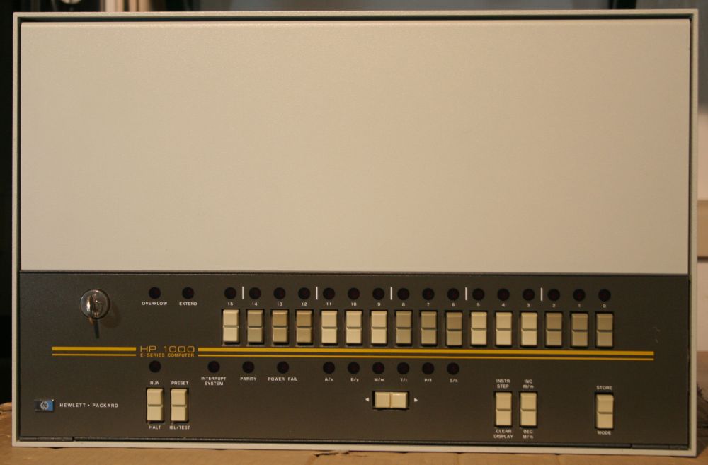
The front panel.
Some recent purchases of equipment produced a cascade of effects. One was my workspace finally becoming completely unworkable due to lack of space, and places to usefully put the new equipment. Hence the recent rearrangement and building project. Which has only solved the space problem in one area — there are other parts of my workshop that are still stupidly over-packed, to the extent of obstructing real projects I need to do.
Fundamentally, I just have too much stuff. A lot of it was acquired on the basis that I'd like to do things with it, in the future when I get some free time from all the other projects. Or because I like collecting interesting historic technology — otherwise known as Boat Anchors. Sometimes it was just that I saw some wonderful old bit of technology about to be willfully destroyed and could not bear to see that happen. So rescued it.
Another result of recent purchases, is I'm now totally out of money. (It's not worth going into my financial situation or why it's like that, but 'totally out' is not a euphemism.) Not unexpected; it was going to happen, and so I made sure to get some things I needed for long-term projects while I still could.
So now to drown two birds with one boat anchor - sell some stuff.
One precious relic I've long known I should get rid of, is my HP 1000-series minicomputer system and accessories.
It's a very nice machine, and the idea of spending some time restoring and playing with it 'some day' is very appealing. The history of early computing is something I find fascinating, while Hewlett Packard (as they were in the 1950s through to the 80s) is definitely my favorite high-tech instrument maker company — verging on hero worship. Since the 1000-Series was the first minicomputer model Hewlett Packard made, to me it's the intersection of two fixations. When I discovered my one, it was about to be destroyed then become landfill. So it had that 'one small thing I can do to fight the Stupidity' appeal. There really wasn't any question.
Plus the machine has quite a clean processor architecture too, by all accounts, and I've been longing to have a good look at it … eventually.
There's yet another appeal; it has a front panel with register LEDs and bit toggles. This is actually something approaching a fetish with me - I really, really like old computers with LEDs and paddle switch front panels. The early DEC PDP-8 and PDP-11 for instance, complete with those oh-so-60's color schemes. I wish I had one of those! Alas I've never found one that was available to me and my perpetually miniscule financial resources. The HP 1000 is cute, but the front panel rocker switches just don't appeal to that particular paddle switch kink of mine. But close, close...
On the down side, although the system I have is very intact, unfortunately I have no winchester hard disks, terminals, bootable media, etc. This means the system isn't complete in terms of being brought up as a working, bootable installation. To get it there would require quite a lot of hunting and effort.
I do have two HP 7970B tape drives that came with the HP 1000 mini, complete with interface cards and cables. Apparently the system could boot from tape, but I have no original tapes.
The real killer for me though, is the HP-1000 and two big tape drives take up a lot of room, on the scale of my storage needs. The two big tape drives in particular have wedged an area of my lab that I want back to use for an aluminium anodizing setup.
So, it has to go. I'm already looking forward to the free space.
However I can still have fun with the machine first, by tearing it down, cleaning it, and seeing if I can get it working. (Not to mention for a better sale price.) I've never had an opportunity to even try running the machine, since when I got it originally I was busy housebuilding. Ever since, there's always been other more urgent things to do.
Hence this teardown thread. It's really a 'farewell my dear minicomputer', and a bit sad.
However realistically, I know I have too many other projects... too many to ever get through in my remaining years. I'll never have the time to really get this old thing to the stage of a fully restored system with correct peripherals, and so on. It will only sit around gathering dust.
Much better to give it what it deserves — a good cleaning, inspection and photoset put online, and attempt to get it to run a few lines of code. A respectful sendoff, hopefully to the hands of someone who'll appreciate and perhaps even use or publicly display it. So here we go.
The front panel.
This is a HP 1000 E-Series Minicomputer, model 2113E, with Options 004 & 014.
It's not what you'd call a desktop computer.
Intended to be rackmounted, it measures 482 mm wide x 310 high x 580 deep.
No, it isn't turned on yet. With old, precious electronics that has been sitting in storage for years you never just turn it on. There's a lengthy proceedure to go through first, including cleaning it inside and out, carefully inspecting everything for problems, gradually energising the power supply to help old electrolytic capacitors re-form the insulating barrier, checking power supply rails are sensible and come up in the right order (so as to not destroy the whole machine in one pop), and so on.
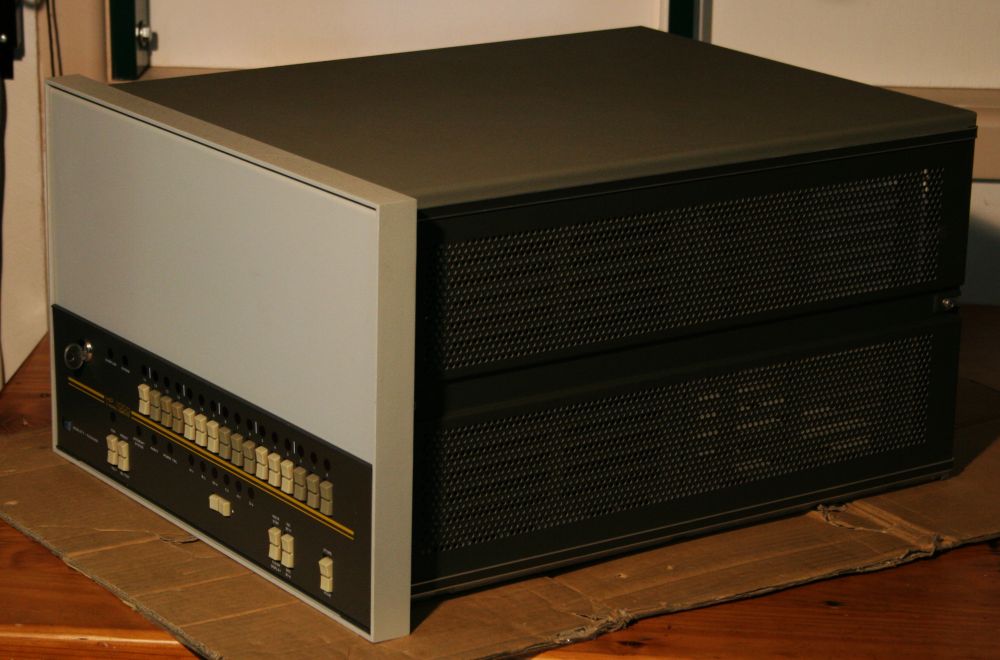
Actually, those pics are getting slightly ahead of things, since they were taken after the teardown and case cleaning. In them the machine is mostly empty. But clean!
The two HP 7970B tape drives are still in storage, and won't be dug out until I'm finished with the processor unit. Lack of space, plus they are very, very heavy, so minimizing moving them around is important (for my back.) Here's a pic of one of them, taken over 10 years ago.
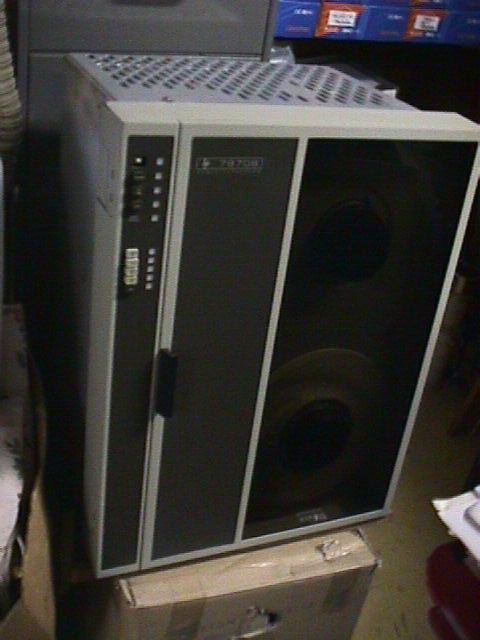
Crummy quality due to early digital camera. This unit is in good condition apart from a missing button. The other unit has some external damage, but unbroken buttons. Back around then I swapped the buttons. So now one tape unit is fully intact, the other one is for spares or repair. Incidentally, it comes with the original connectors and cables between the HP 1000 I/O cards and tape drive unit.
So, on with the teardown and cleaning. Lots and lots of cleaning...
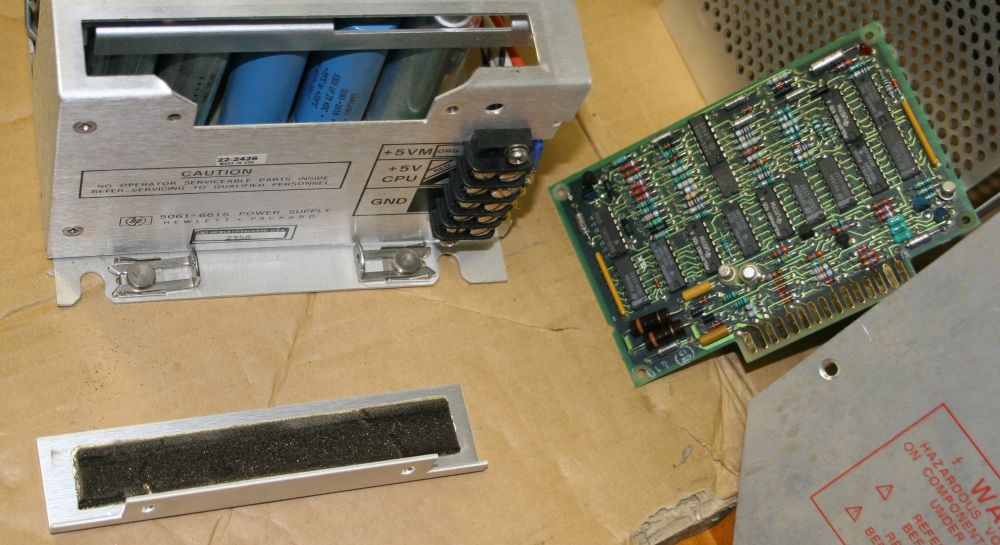
Top cover removed. There are basically four parts to the system: power supply (foreground in photo), I/O cardcage (left rear), memory cardcage (right rear), and the processor board (underneath, not visible here.)
What is visible here is dust. Some of it my fault - back around 2005(ish) there was some carpentry I needed to do, and no other place to do it than my main workshop. I covered all my equipment including this thing with plastic. But have you ever used a router? (Woodworking, not networking.) They make incredibly fine dust, that seems to laugh at plastic drapes. Any barrier that isn't totally hermetic is futile. When I discovered how badly it was dusting up all my equipment I stopped. Won't be doing that in my electronics area again! And so since the 'dirty work' separate workshop is still unfinished, so are most of the wood and glass panelling doors on all the cupboards around here. Oh well...
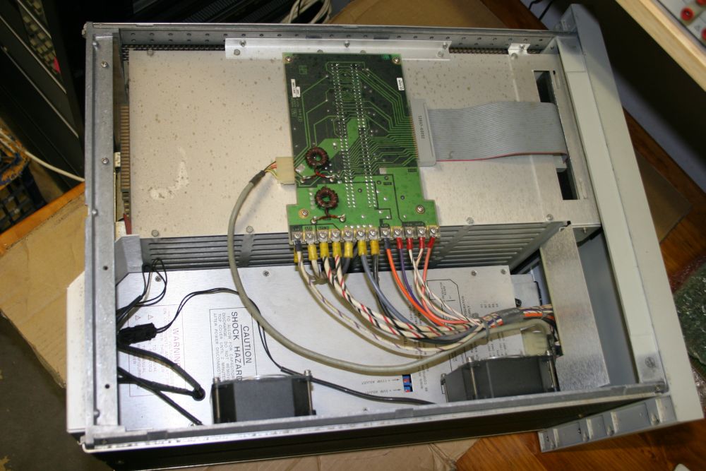
The PCB visible is mainly the interconnect between the two card cage backplanes and the power supply. The small round gray cable is power control signals, while the ribbon cable goes to a front edge connector on a card labelled "D.C.P.C." - don't yet know what that stands for, but it's providing an interconnect between the memory & processor support card cage, and the I/O card cage.
By the way, as this progresses I'll be referring to the following information sources:
vintage-computer.com - Some history of HP and the HP 1000 minicomputer.
http://bitsavers.trailing-edge.com/pdf/hp/1000/
http://bitsavers.informatik.uni-stuttgart.de/bits/HP/HP_1000_software_collection/specials/index.html
Bitsavers maintain a huge archive of saved documents and code, for all kinds of old technology.
Additionally:
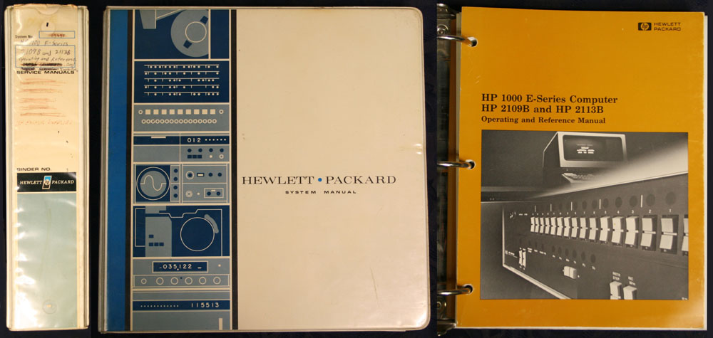
Some years ago I was lucky enough to find this HP 1000 manual on ebay.
A 3-ring binder, it's obviously been used quite a bit. Rather sad that it no longer contains some of the things hand-written on the spine, but what it does contain is not bad:
* HP 1000 E-Series Computer
  HP 2109B and HP 2113B
  Operating and Reference Manual
  PN 02109-90014  February 1983
  (Stiff board cover. 2-colour printing on glossy paper. Excellent condition. 64 sheets.)

* Batch-Spool Monitor Reference Manual
  (Stiff board cover with photos only, remaining pages missing, dammit.)

* Input/Output Instruction Group, I/O Channel, and I/O Extender Diagnostic
  Reference Manual
  PN 02100-90213   April 1982
  (21 sheets. Black printing. Stapled together at corner. Handwritten '7603' on title sheet.)

* HP 1000 E-Series Computer
  HP 2109B and HP 2113B
  Installation and Service Manual
  PN 02109-90015  February 1983
  (Stiff board cover with B&W photo. 24 sheets incl 4 foldouts. Some hand yellow highlighting.)

* A set of firmware/hardware notes, missing cover so overall title unknown.
  Had been all stapled together, now loose. Some yellow highlighting throughout.
  In general they are installation/setup instructions.
  - Section I   HP 13304A Firmware Accessory Board          (3 sheets)
  - Section II  HP 12791A Firmware Expansion module         (3 sheets)
  - Section III HP 13197A Writable Control Store            (5 sheets)
  - Section IV  HP 1000 E/F-Series Dynamic Mapping System   (2 sheets)
  - Section V   HP RTE IV A/B Extended Memory Area Firmware (1 sheet)
  - Section VI  HP 13306B Fast Fortran Processor Firmware   (1 sheet)
  - Section VII HP 1000 F-Series Dynamic Mapping Instructions and
                Fast Fortran Processor Firmware             (1 sheet)
  - Section VIII HP 1000 F-Series Scientific Instruction Set Firmware (1 sheet)
  - Section IX  HP 12824A/29A Vector Instruction Set Firmware   (1 sheet)
  - Section X   HP 91740B Distributed System Firmware       (2 sheets)
  - Section XI  M/E/F-Series Control Memory Allocation      (2 sheets)
  - Section XII HP 1000 E-Series Base Instruction Set and EIG/Floating Point Firmware (2 sheets)
  - Section XIII HP 1000 F-Series Base Instruction Set and EIG/Floating Point Firmware (2 sheets)
  - Section XIV E-Series RTE-6/VM Operating System/EMA/VMA Firmware (1 sheet)
  - Section XV  F-Series RTE-6/VM Operating System/EMA/VMA Firmware (1 sheet)
  - Appendix A  HP 12823F F-Series Enhancement Upgrade Kit    (1 sheet)

* 3 sheets lined green notepad paper, with handwritten service notes
  Covering '9836' and 'Double sided 8" Drive"

* 6 sheets of paper, dot matrix printed, quite battered and with some hand notes,
covering:
  - Start up proceedure for the HP1000 Computer
  - HP1000 Shutdown Proceedure
  (These came with the machine I have.)
That's not the only thing that has to be digitally secured. As I started extracting the boards, I was grateful to find that most programmable devices are ROMs. No 'EPROM evaporation' to deal with. But then... sigh. Nope, there are some EPROMS. The good thing is they are on a type of IO card that there are four of. So I'm hoping that at least two of those EPROMs compare the same.
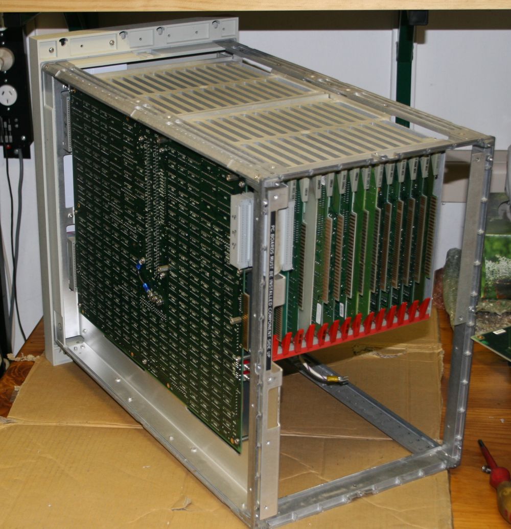
Getting ahead of things again. This is the rear of the machine:
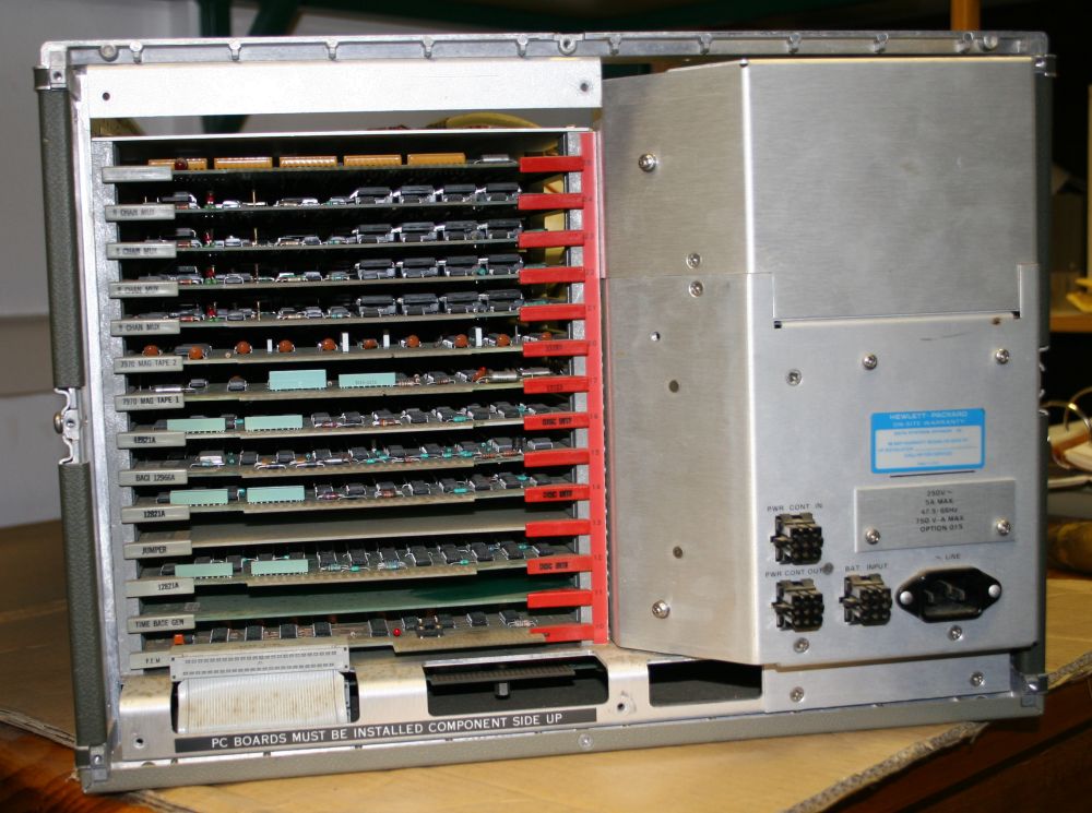
Looking at the I/O Card Cage rear, and power supply. Unlike a couple of other machines I've seen for sale now and then, this one is fully loaded in the IO card cage. Oh and there are a few other boards that come with the system too. Will get to that later.
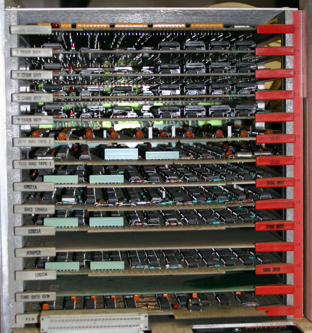
Close up of the I/O cards.
Notice the red strip with the slot numbers? See anything odd?
It made me laugh when I saw it. If you read my 'Retarded ideas in Computing Science' post, you'll remember the conflict between my love of old computer hardware, and my deep loathing of the Octal numbering scheme.
So, I wonder what's behind these physical card slots being numbered in Octal? The count goes 15, 16, 17, 20, 21... Ha ha ha! Whyyyyy?! Was it a little joke, or is there some slot interrupt numbering or something that really needed it like that?
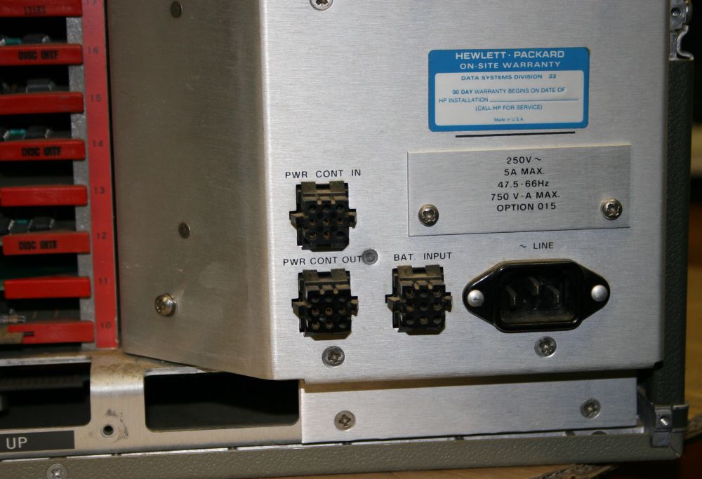
The rear power connectors. The labels say the machine is wired for 240VAC, but that's something I'll be checking before applying power. A more serious worry is those three rectangular black connectors. When I got the machine it had one 'jumper' plug with it, that fits these. But which one? Don't know. I'm guessing it would be the 'Power Cont In', but that will have to be determined for sure.
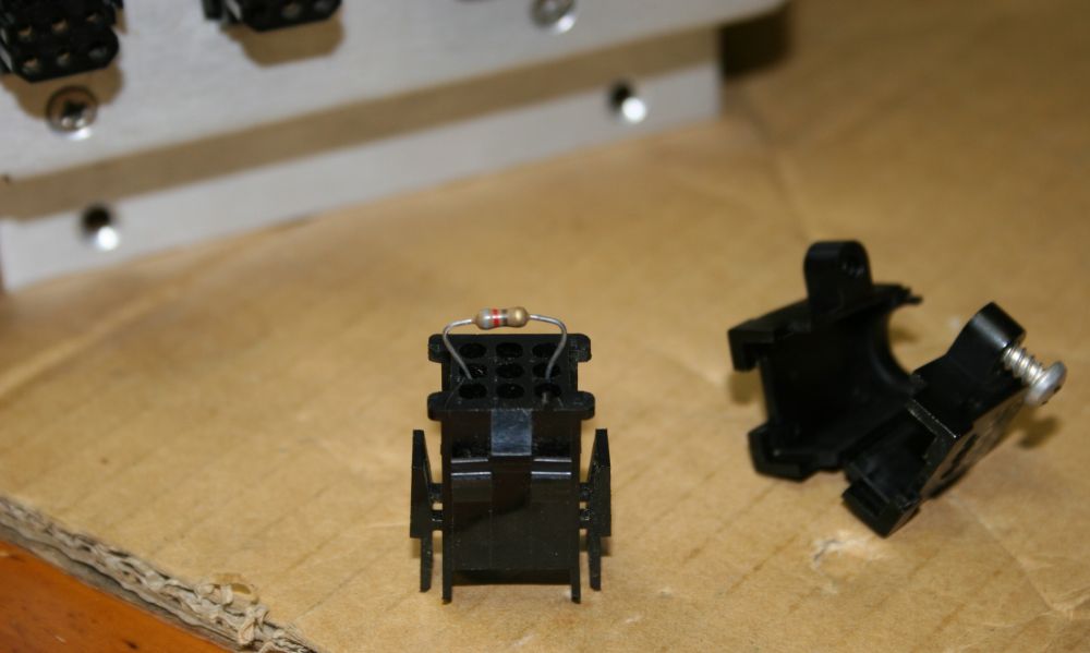
The jumper plug, opened up. It contains one 820 ohm resistor.

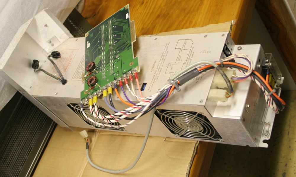
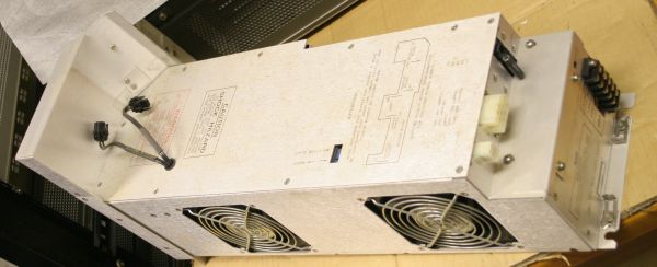
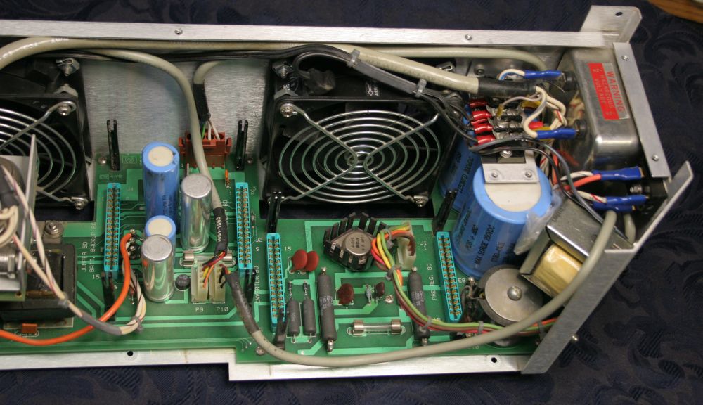
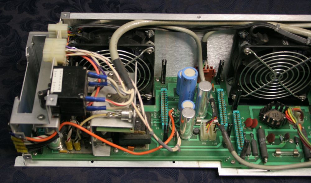
With the power supply removed. Just three screws and a couple of clips, plus three leads to free, and the power supply slides out easily. Nice. Also a first view of the processor board, peeking though cutouts in the baseplate.
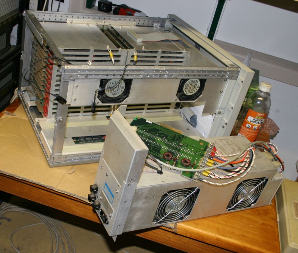
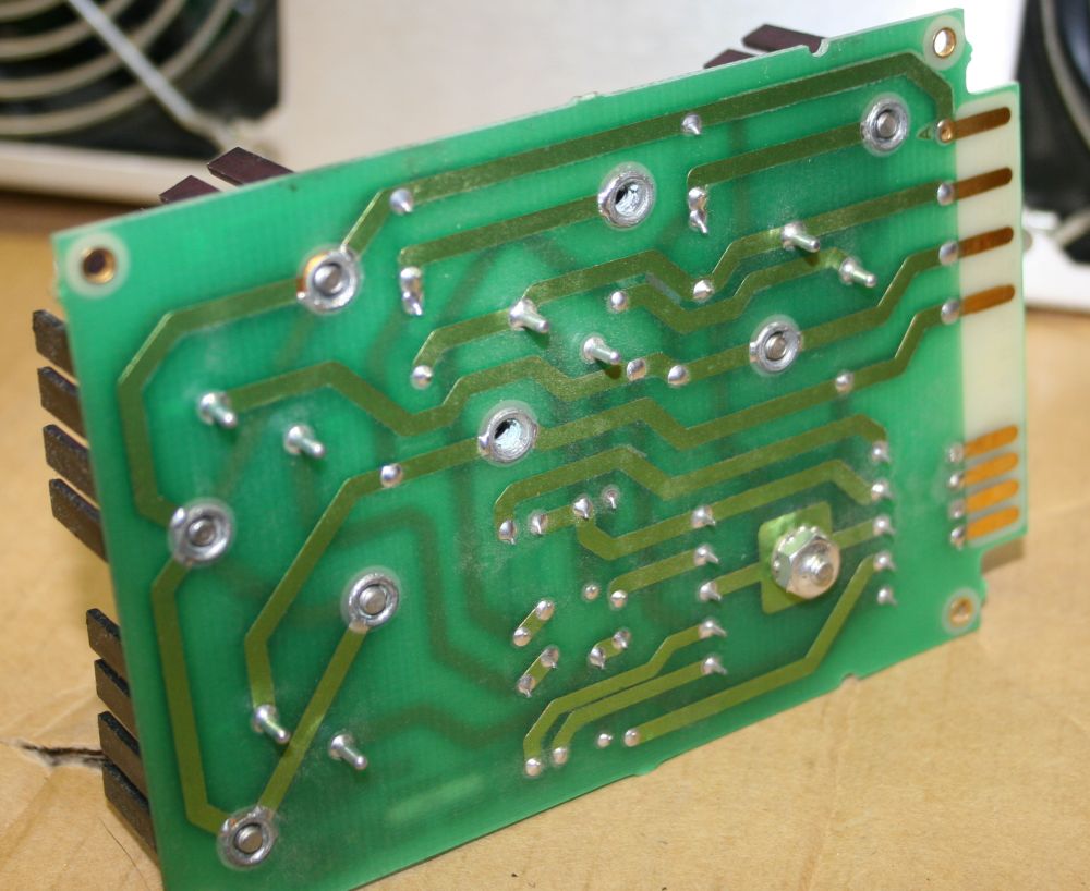
The power supply, with backplane power board still attached.
The machine front panel hinges down once the key is unlocked. Then two screws to remove the front card cage cover.
Oh thank you, thank you fate! — HP didn't use stick-on urethane foam as a board and connector retainer. Whatever this foam sheet is, it's not urethane, and seems in perfect condition. Maybe some silicone type?
Anyone who has restored old electronics will understand my joy. You see urethane foam turns out (after about 20 years) to undergo some decay process that turns it into the vilest sticky black sludge. Which is resistant to removal by virtually every solvent that won't give you cancer or destroy the item you're trying to clean.
Looking good so far - I haven't seen any urethane foam in this machine yet. Such a pleasure!
I'm not so excited to see the frequent use of insulation displacement connectors and ribbon cable throughout. From my days as a service tech long ago (not on machines like this) I developed a strong distaste for IDC connectors. One of the more unreliable system components, as the contacts between wires and pins tend to go bad. And there are a lot of contacts.
Maybe these ones are better. I hope so. Running a big fat bus on an IDC ribbon cable, to memory cards as HP have done here... does not give me a good feeling about the chances of this machine working right after oh... 30 years?
Side view.
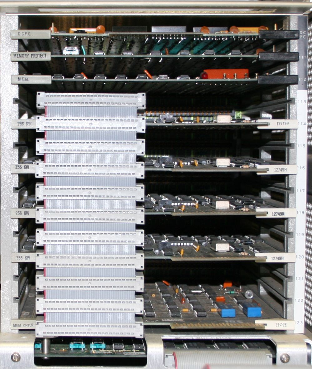
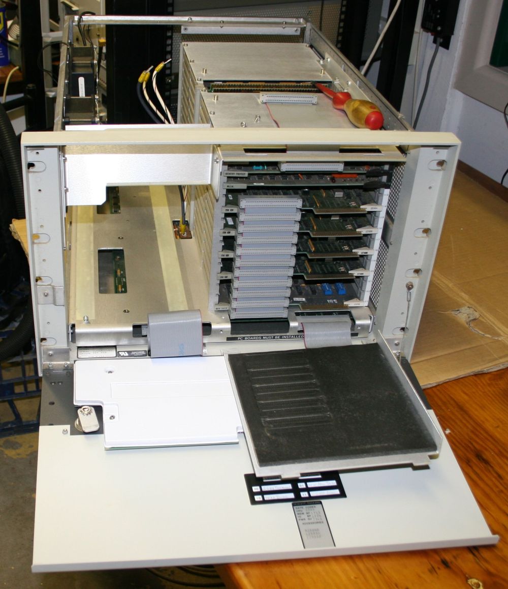
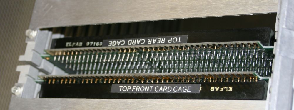
Close up of the front card cage. It seems to be mostly memory-related.
Hmm... Four 256KW cards. That would be 1 Meg of 16 bit words. Not bad at all for those days.
Curiously, the slot numbering in this cage doesn't have that Octal jump, unlike the rear cage. It has its own mysteries - why start at '111', and why is the DCPC slot named as opposed to numbered?
I presume the black/white colour coding of the RH ejector levers relates to whether the slot is for memory cards, or specific control cards.
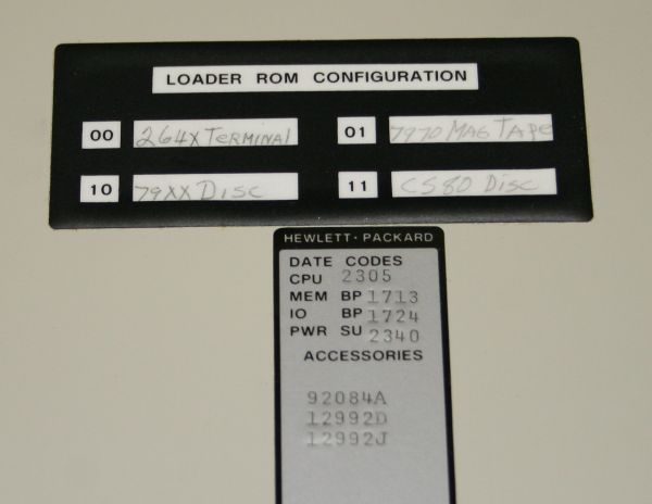
Labels inside the front panel. Sigh. I only have one of the four peripherals listed. Presumably the others made it to landfill before I could find them. What a pity.
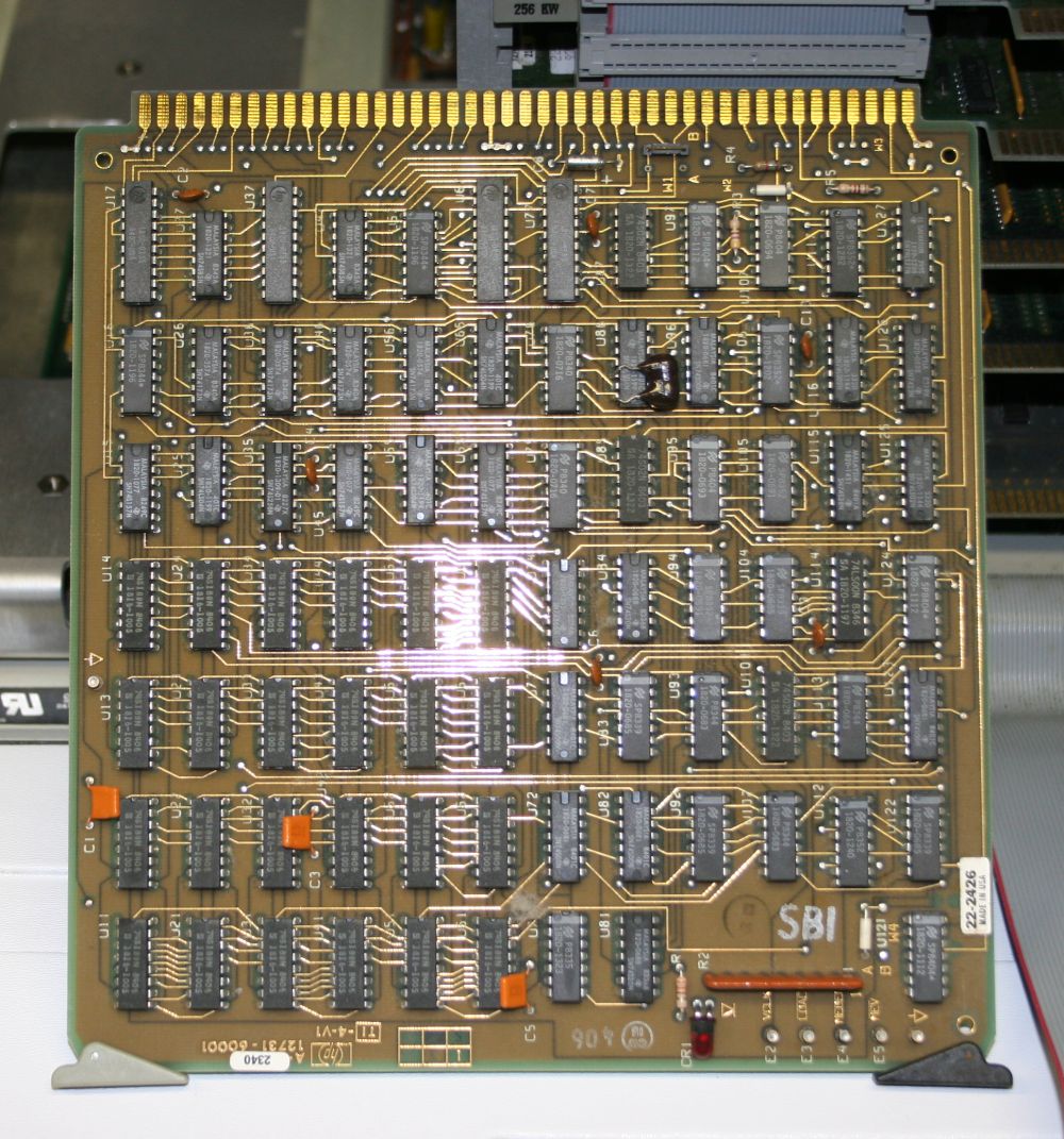
One of the front cage cards pulled, just to wet my appetite (and yours.) All ICs with HP part numbers, not their generic numbers. I wonder if a full service manual with schematics for these machines survives anywhere?
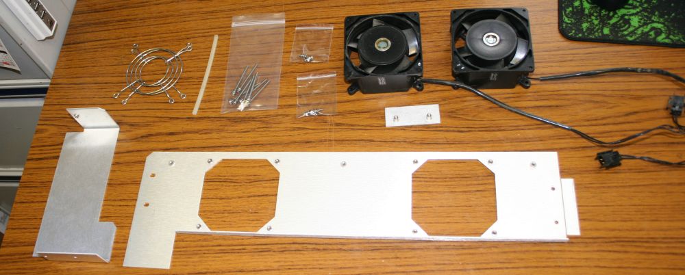
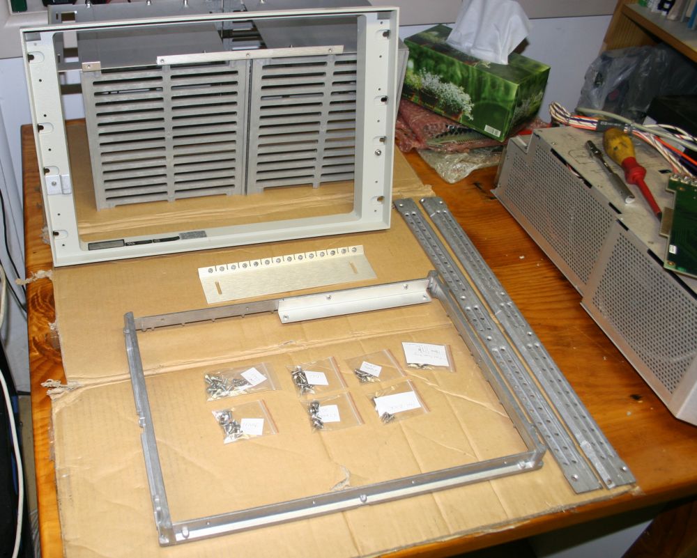
The fans panel disassembled. Everything has to get stripped down like this, for cleaning.
Ziplock bags! What a great invention. Can't be beat, for organising small parts that must not be lost or mixed up.
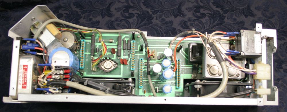
First full view of the processor board.
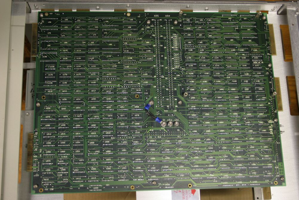
Or rather its underside. The processor board also has direct connections to both backplane cards.
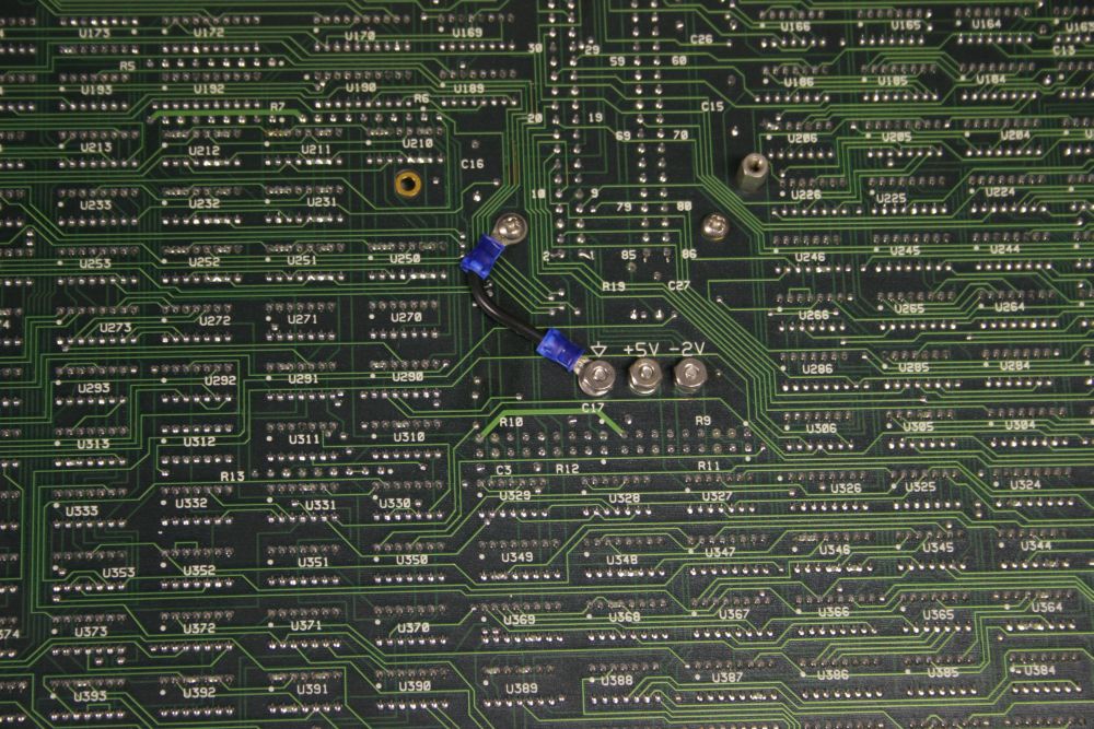
Two power rails, +5V and -2V. So, there's some ECL logic here?
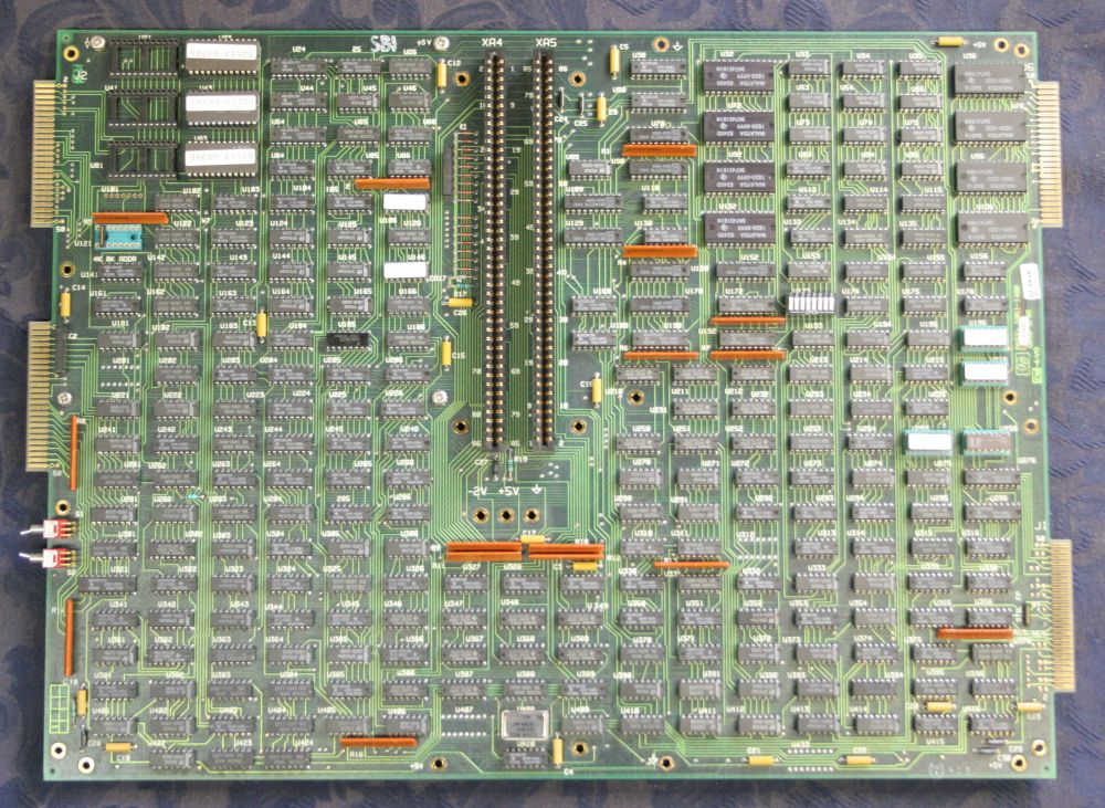
Proper view of the processor, component side.
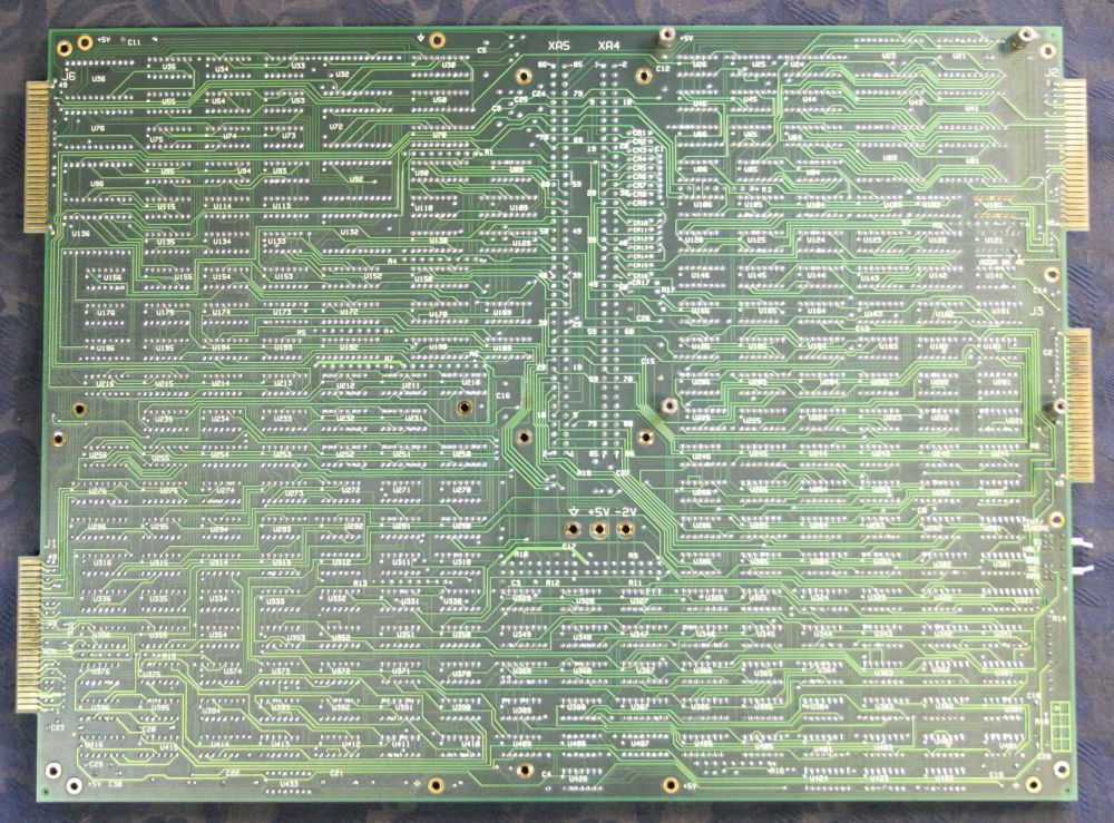
Ditto, the rear side.
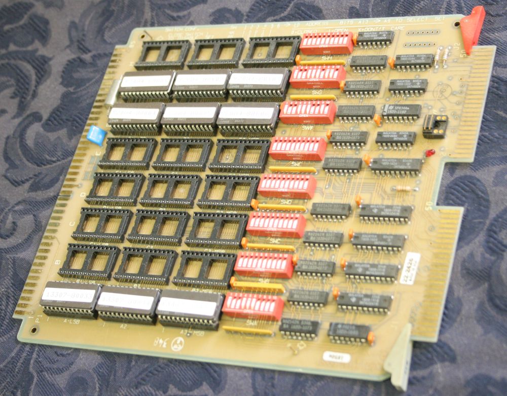
So I'd started pulling all the card cage boards. This one is the system firmware options board. The moment I pulled it out I thought "Photo. NOW! Before any of those DIP switches get accidentally moved." Urrrgh! I can imagine how much trouble just one bumped switch here could cause.
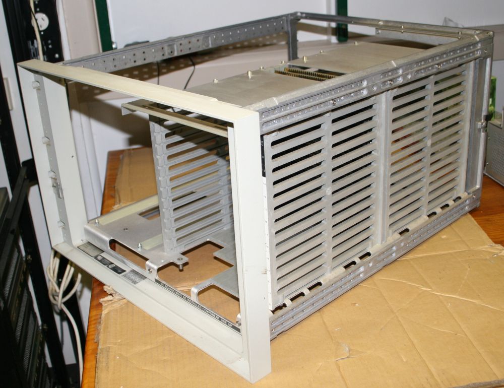
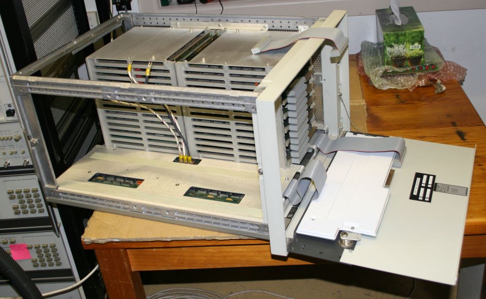
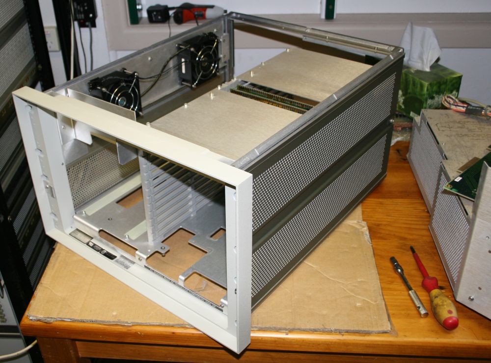
A very gutted system frame. There's just a couple of cards to remove - the backplanes.
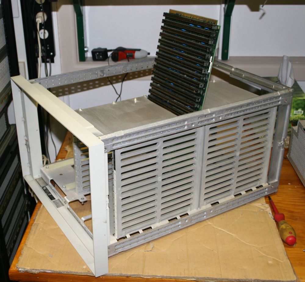
Do you know how much trouble it is to remove backplane PCBs from virtually any system that has them?
Normally it's a collosal pain in the arse, with at minimum two awkward to remove screws per slot.
Well not with the HP-1000! Once all the cards are removed, the backplanes just slide out! That's it! There are no retaining screws or anything! The backplanes are held in place entirely by all the other cards and a couple of slots in the cage. Genius!
But wait, there's more! Often when disassembing stuff you get the feeling the designers wanted you to put it back together wrong, so you'd break it and have to buy another from them. Not HP! How plain and helpful can labelling be? This!
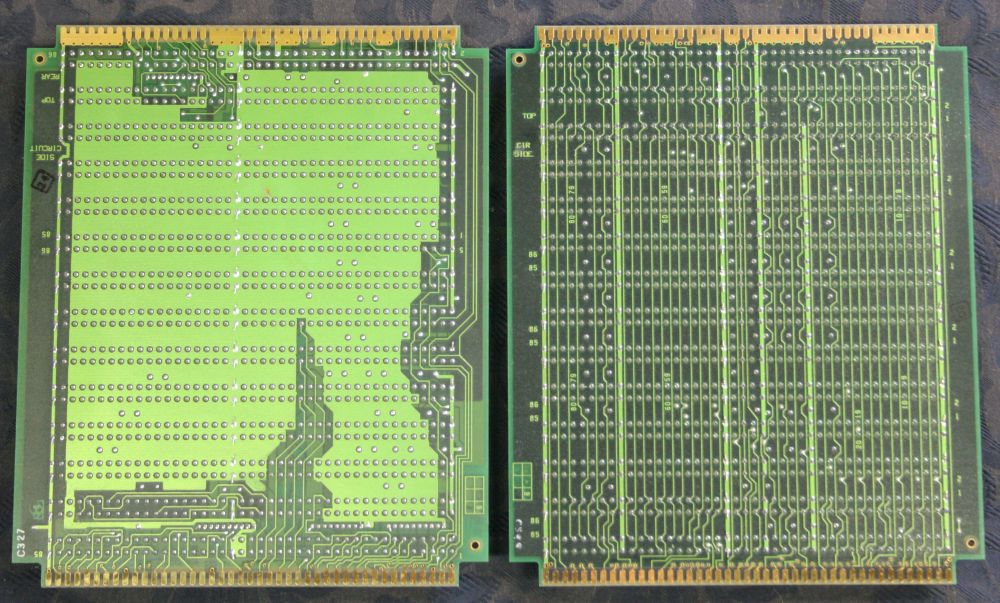
The two backplanes, solder sides.
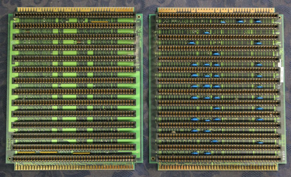
Component sides.
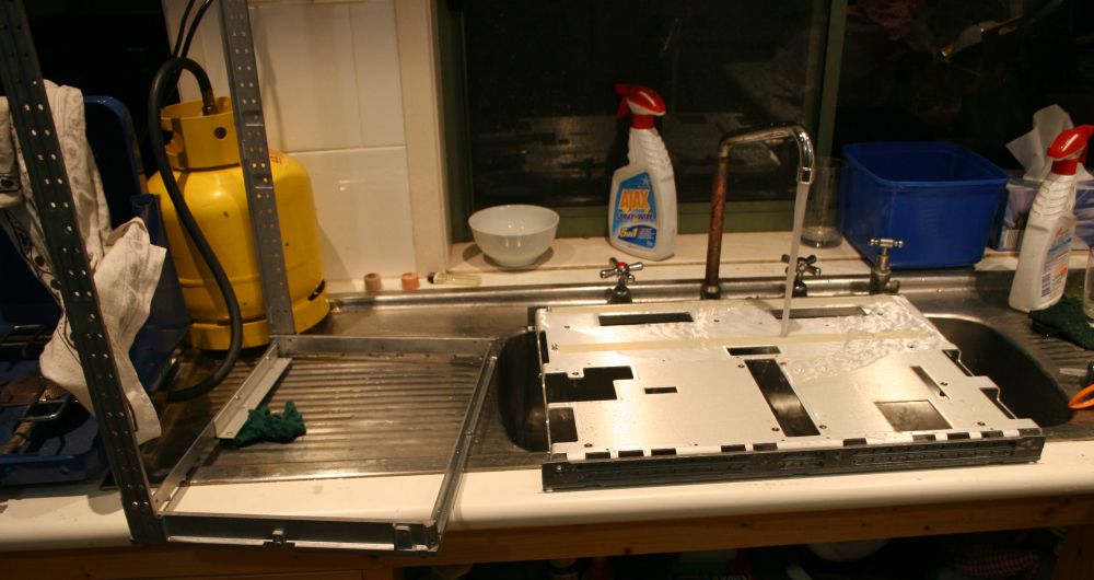
Meanwhile, in the kitchen. I haven't been showing it, but every piece of metal removed has been getting a scrubbing. Mostly I can get them looking like new. It's nice that the whole machine is in such good condition overall. No dings at all, virtually no scratches or stains. Compared to some machines I've cleaned up, it's a pleasure.
Point being, as I take this apart all the photos are pre-cleaning. There'll be some at the end showing the gleaming beauty of a like-out-of-the-box restored machine.
The frame of the HP 1000 is very minimalist. That's it there, apart from the baseplate.
Reassembly begins. That's the frame done - easy stuff first. Next is the power supply.
Thinking about where to begin. Removing the cables for a start.
They go like this. No, I don't trust my memory, or that colour codes, etc may match printed instructions.
Without the wires.
Top cover removed.
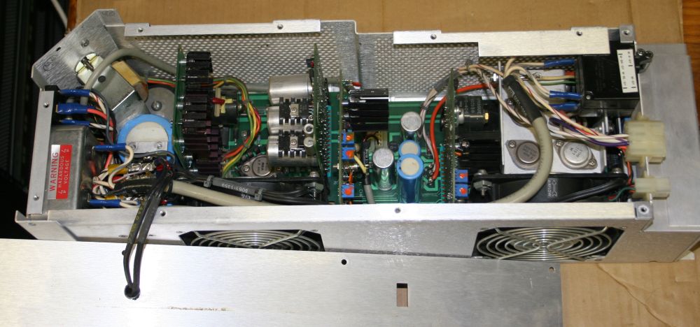
Caution! There is a mysterious error here. MUCH later (2021 via cctalk@classiccmp.org) it was pointed out that the two riser cards at left are swapped. The card with the silvery electros should be leftmost (it is the "pre-regulator board.") The card with the several TO3 transistors on large black heatsinks is the "inverter board" and should be where the pre-regulator is in this photo.
The layout as printed on the power supply cover in the next photo is correct. But at the time I didn't notice there was a discrepancy between the cards and card position diagram. The cards are not actually labelled with their names, you have to deduce their function from the nature of the circuitry. Which is obvious once you pay attention.
How did these boards get swapped for this photo? I am pretty sure back in 2013 I took the photo before moving anything. 'Photos first!' is a rule I apply quite strictly. (But maybe I had a brain fart this one time?)
Another possibility, is someone decided to make the system mysteriously non-functional when it was being de-commissioned, hoping to acquire it cheaply themselves? It isn't much work to get access to this state, if that's all you want. I much perfer this version, in which I am not going senile.
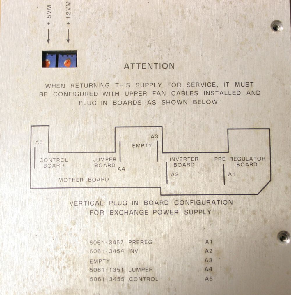
Interestingly the diagram on the cover doesn't exactly match the contents. For instance 'A3' slot is not empty.
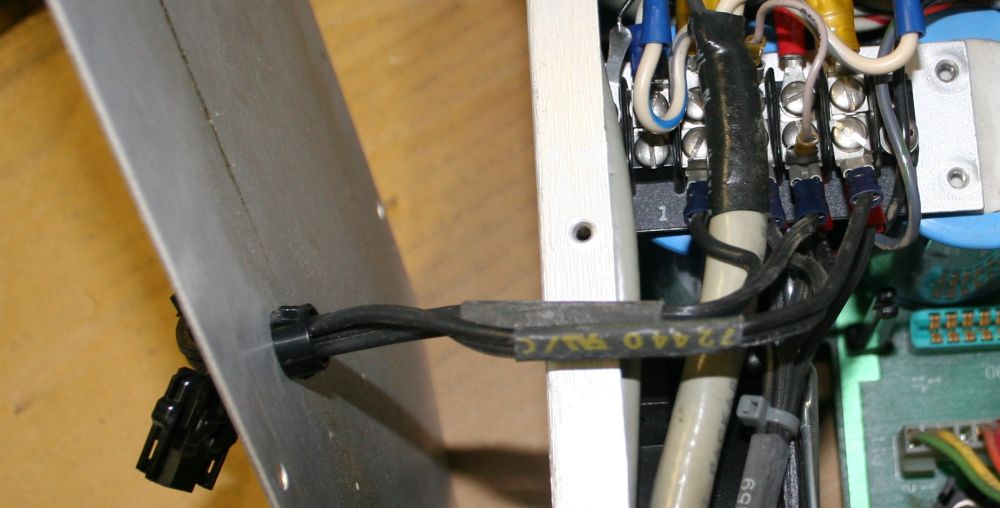
Taking a note of how the two 115V fan cables attach, before I remove them.
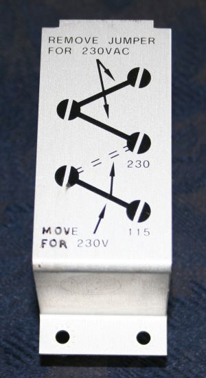
The small gray jumper in the previous photo is the mains voltage setting. Set for 230V.
(2021: Correction! This is the Inverter Board, NOT the Pre-regulator Board. And that whole mechanical interferrence problem vanishes when the two swapped cards are returned to their correct slots! I'm leaving the text below as-is, to show how confused I was by the unexpected board swap.)
The "Pre-Regulator" board. Something struck me about those transistor legs. With the board plugged in, the leg ends press against the side of one of the large electros. Huh, seems a bit careless, why didn't they clip them short? Pulled the cards, thinking I might trim the legs to fix that mechanical interference. It actually pushes the card a little to one side. On inspection, those legs look strangely thick, and why weren't they clipped short before, anyway? Could those be...?
By golly, they are! They are miniature soldered-in pin sockets. All these TO3 transistors are plugable, for easy replacement.
I guess I'm not clipping the 'legs' after all.
Ha ha ha ha! So, there IS some urethane foam in the machine! One small strip, used to extra-securely hold one card in place in the power supply. The 'control' board. What's the bet this foam was an afterthought? After one of these boards worked loose and caused the supply to go over-voltage and destroy everything in a machine. Expensive! So, add some urethane foam, that won't cause any problems, ever. Right?
Well at least the decay process is only just begun here, and the rotting foam seems to be all still in place, rather than distributed through the machine in sticky, corrosive fragments. Needless to say, I removed it completely. 'Mechanical scraping is the only way', as they say. Followed by hot air gun to peel the backing adhesive strip off, then solvents to get the glue off, then scrubbing and polishing to get the metal clean. Oh I love urethane foam.
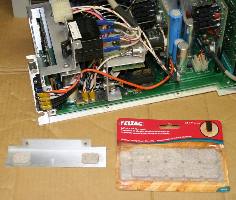
To reproduce the 'firm holddown' of the card, I used some furniture base stick-on felt pads, that were just the right thickness. They are some form of felt made of very tough fibers. Should be good for the life of the machine. Unlike urethane.
Stripping the supply down for cleaning. In this case with compressed air and brushing.
See the little folded up plastic bag, wedged between the big blue electrolytic and the small transformer?
It contains the other two jumper leads needed for 120V operation. Someone shoved them in here when converting this machine to 240V for use in Australia. Instead of just throwing them away. That was thoughtful, thanks to whoever did that.
(2021: Hmm. So someone involved in maintaining this machine in its working life in Autralia had seen inside this power supply. Was that who swapped the boards later, on decommissioning?)
All the electros look fine to me. No signs of leaking or corrosion. I think I'll give them a pass for now, and see how they go with power.
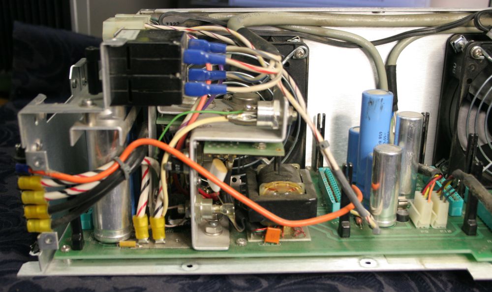
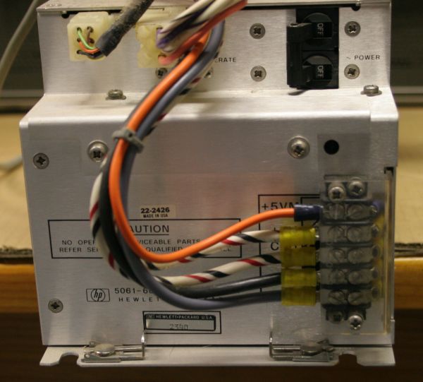
Final output stage.
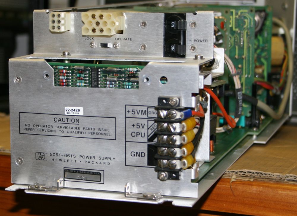
Closeup of the back. Hey, there's a little slider switch hiding under that big white nylon connector. I didn't even see that before. It's labelled 'Lock' and 'Operate'. Presumably 'lock' means 'don't operate' and it's quite well hidden when that cable is plugged in. Is it a 'secret' way to prevent others from turning on the machine? I'll be interested to see what the documentation will say about this.
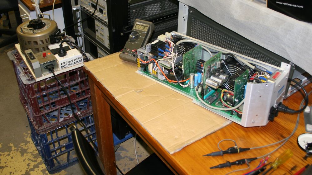
A first power up test. Without the black rear jumper plug. Mains increased slowly via Variac at first. No bangs or smells, which is always a good start. Also it's not dead. The main 5V rail ramps up slowly to about 3.2V, and stays there. All other rails are zero. Considering nothing is plugged in, that's not unreasonable behavior. I'd expect it to try a soft power up, realise something's wrong with its load and halt.
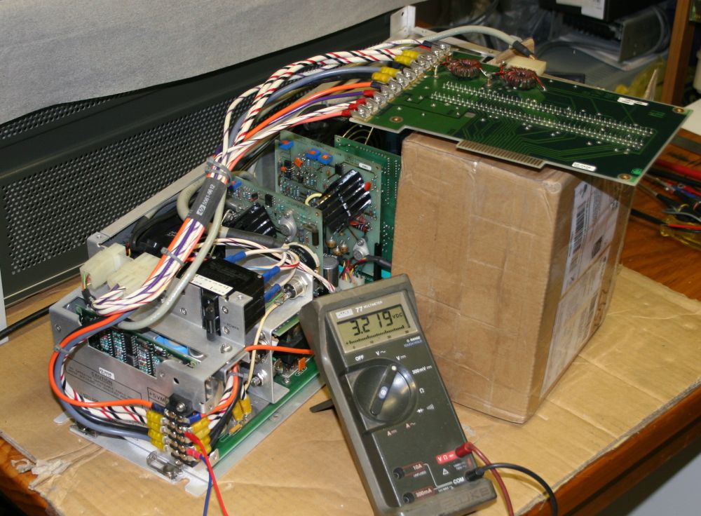
Adding the backplane power interconnect card. Nope, as I expected it didn't make any difference, since most of the signals on that small 'control' plug come from signal lines on the backplane. It's going to take a bit more subtlety to make this thing believe it has a system attached. I'm not going to just plug everything in and try it.
So it's Research time. Need to find a manual for the power supply.
Plenty of other things to do in the meantime. For instance scanning the manuals I have.
To be continued
Meanwhile, my attempt to scan the first of the manuals has also hit a bit of a problem.
I'd appreciate any suggestions.
The disassembled HP 1000 has been sitting in a box since then. I had changed my mind about selling it, after I learned of the HP 1000 feature of user-extensible microcode. That really interests me, so it's a keeper. My storage problem is somewhat alleviated by a building extension. In late 2017 I joined a couple of mailing lists for vintage computer enthusiasts, which solves the difficulty of my not knowing anyone with expertise in these old systems. Enough time has passed now. This year (2019) I'll get it under way again.
Positives: