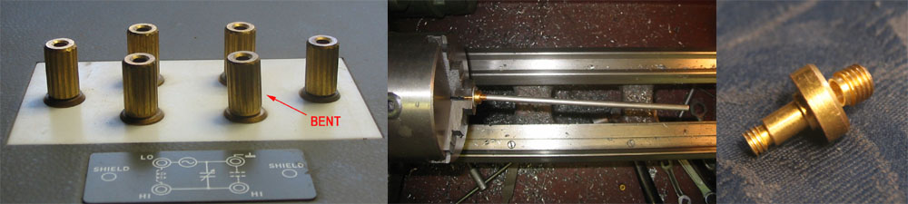
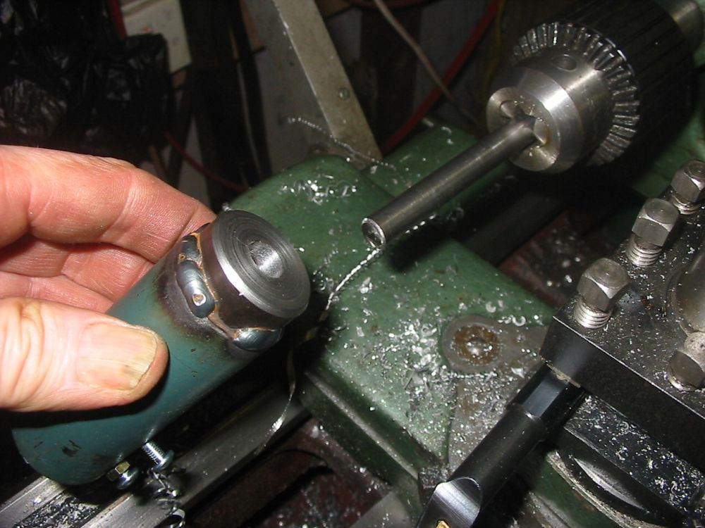
The bent post, how much it was bent, and the fractured post base.
This is an update to The Q Meter
To recap: The HP 4342A Q-Meter I'd bought via ebay had arrived with one of the test port terminal posts bent due to inadequate packing for shipment. My attempt to straighten it hadn't worked - the thin brass wall of the post base had fractured, despite my attempt to use pressure rather than tension during the straightening.
The bent post, how much it was bent, and the fractured post base.
By the time I determined the post was unrepairable and I'd have to make a new one, it was Friday evening. Then it turned out I didn't have any brass rod of sufficient diameter for machining a new post, so I couldn't do anything more till Monday.
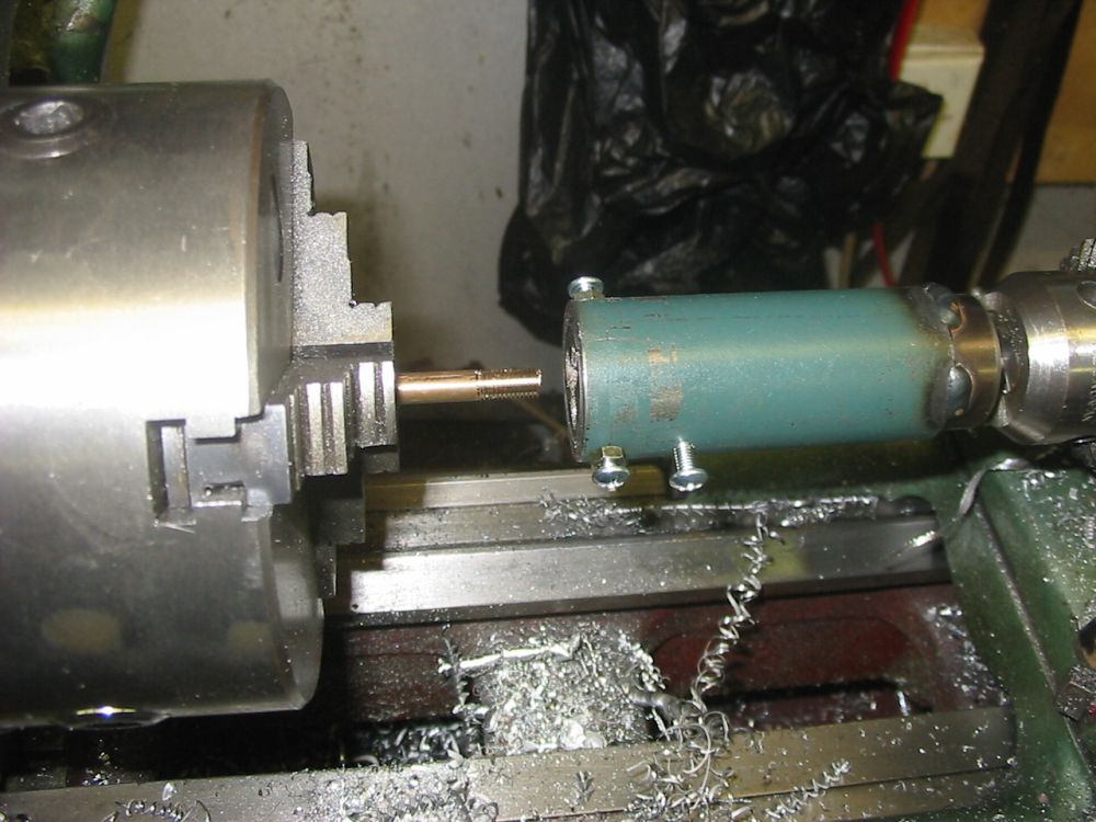
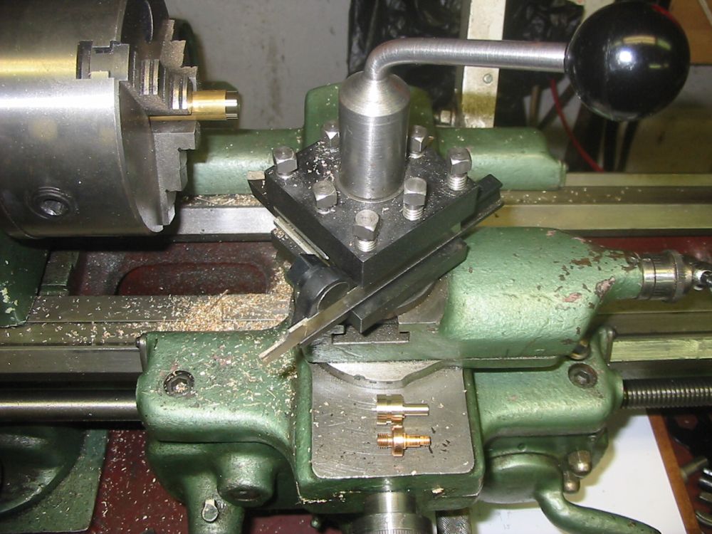
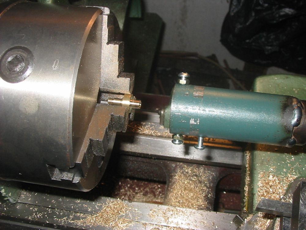
My lathe can do screw thread cutting, but I didn't trust my skill to try doing these small precise threads. So I decided to buy button dies for them. But that raises another problem - using button dies by hand it's difficult to start threads exactly axially on a rod. So the first thing to do was to make a jig to hold button dies axially to the work.
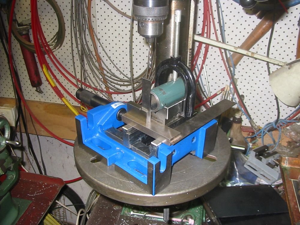
Marking out for screw holes on opposite points on a cyclinder. Sadly all my fabrication skills are self-taught, and I'm pretty sure I'm crap at this. For instance, how do you mark exactly opposite points on a cylinder, without access to the end? I have no idea.
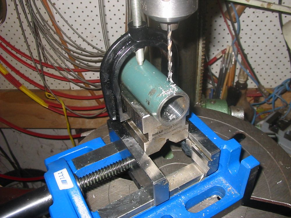
Drilling for screw holes to lock the button die in place.
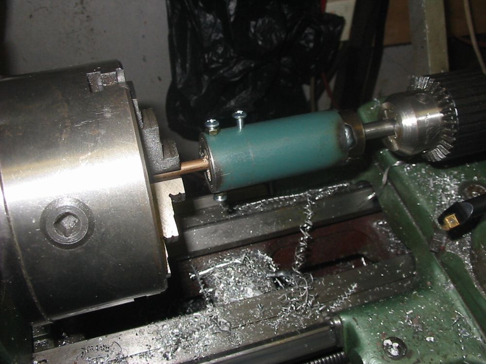
The jig in use on a bit of scrap brass rod. The lathe is just used to hold things axially, with all the thread cutting rotation done by hand.
End result. It works nicely.
The jig just slides along a rod held in the tailstock chuck.
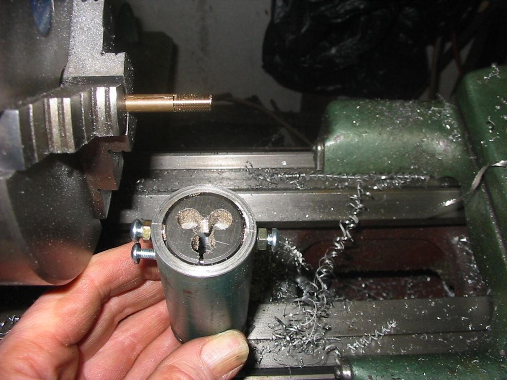
Button dies sit flat against a machined face, to ensure an axial cut. There's room around the die to allow for adjustment of the die thread diameter.
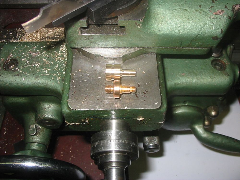
Starting to make the new post. Doing stuff precisely on a lathe with imperial gradations (inches - thou) when all your measuring instruments are in millimeters, is a royal pain ita.
Wider shot.
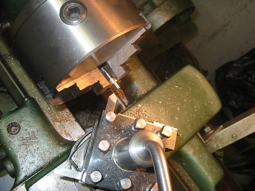
Thread finished on the base end, now roughing the upper end of the post. I'd discovered that the UNF #10 button die had some taper on both sides of the button. So it could not cut the thread fully on the last couple of turns. I'd had to use the thread cutting bit at lower left in this photo, to very carefully lathe-cut the last bit of thread. Turning the lathe by hand, after running along just outside the threads first to check it was going to align properly. It worked, though the thread profile isn't perfect.
Getting there.
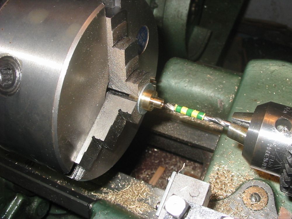
Drilling the hole.
The thread cut. This button die is better. With no taper on one side, it could complete the thread.
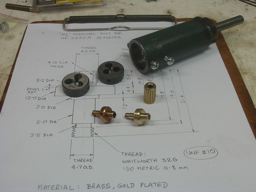
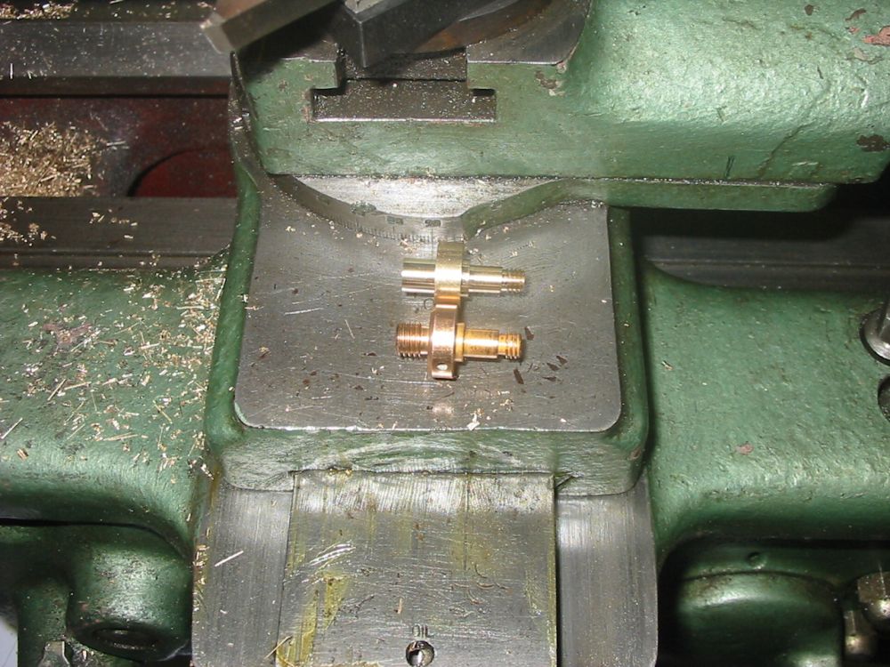
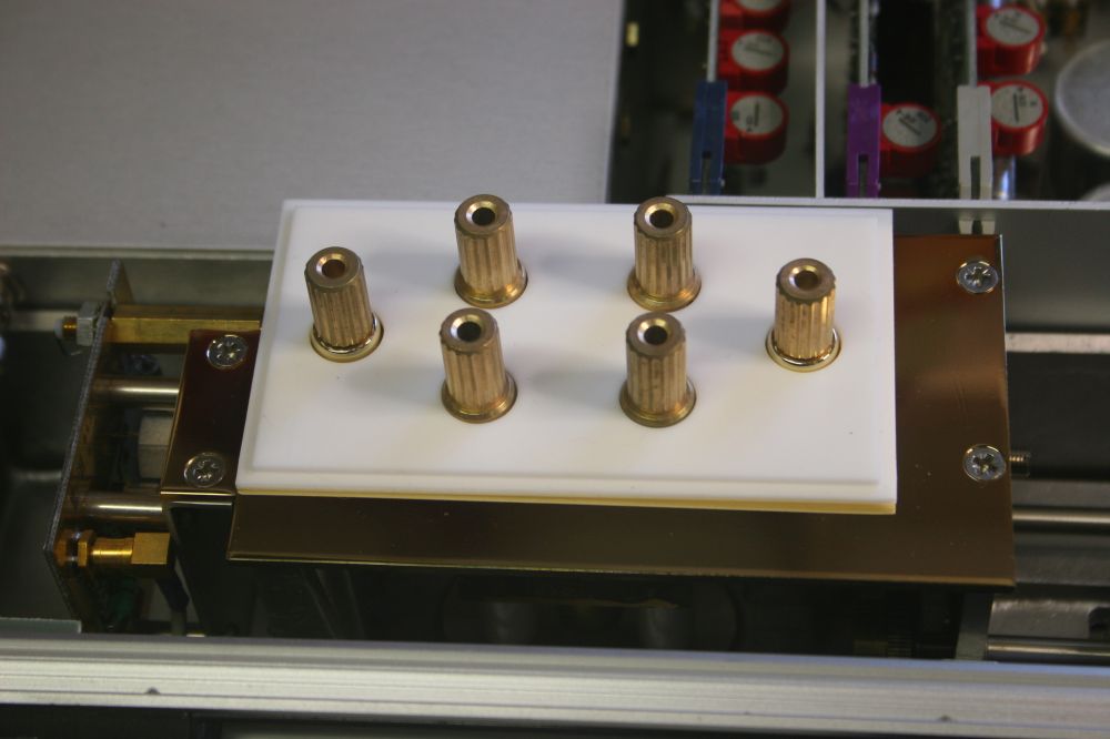
Finished. The other (undamaged) original post on left, my newly made one at right. The post top screws on nicely.
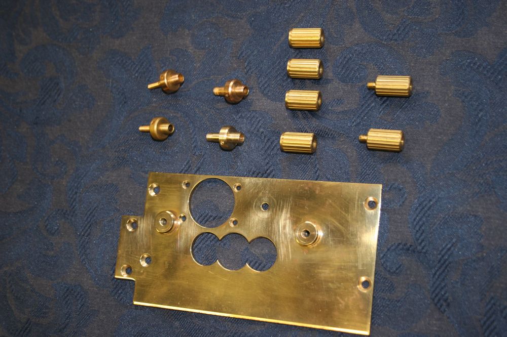
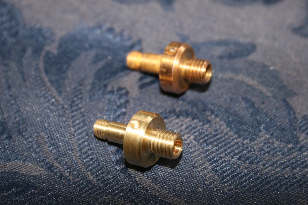
All the parts. Since I have to get the new part gold plated, I might as well restore the gold plating on all of them. After cleaning the tarnish off, some of them look like there's little if any gold plating left.
Closup of the made and original part. OK, I'm proud of it. My workshop is strictly hobby level and I'm not in any sense a capable 'machinist', so it's nice to have something like this work out well.
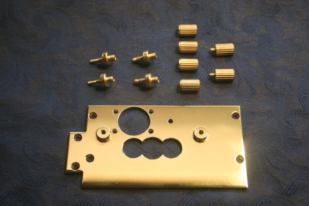
After gold plating. Pretty! I'd expected it might be a bit of a search to find a gold plating service. But serendipitously a post on eevblog.com/forum recommended one that's very close to my home. Industrial & Decorative Gold Plating Co, in Milperra. This plating cost $200, sigh. The overall cost of this Q-meter in money and time is really adding up.
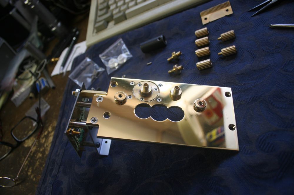
Beginning reassembly.
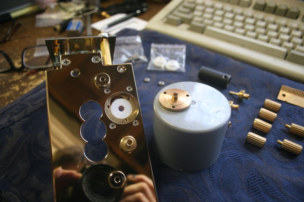
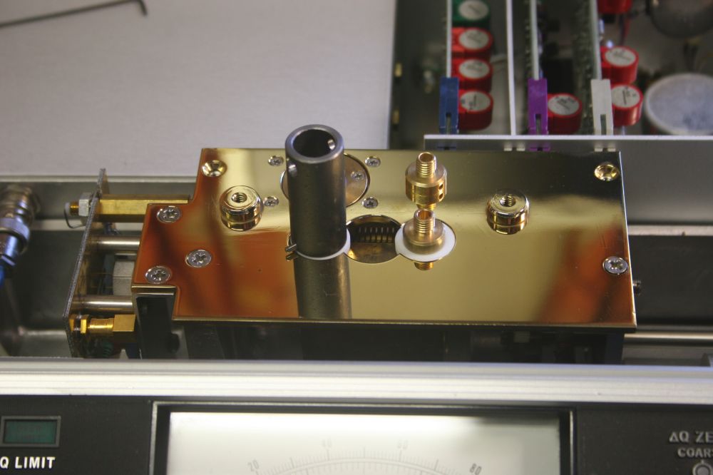
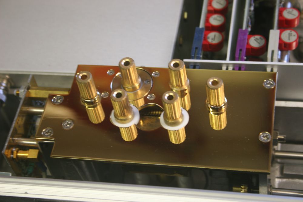
Opening up the 'detector' post structure. The removed disk with projecting cylinder is part of the grounded Faraday cage that surrounds the current transformer underneath.
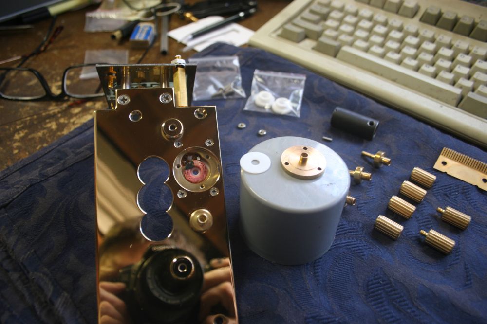
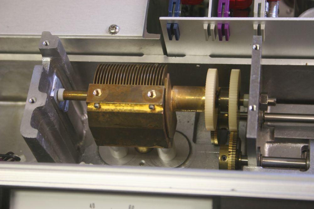
The current transformer torroid. It picks up current flowing in the banana post stud connecting it to the grounded plate.
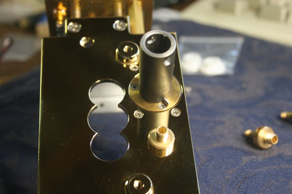
Tightening the banana post studs. Another small special tool made for this project.
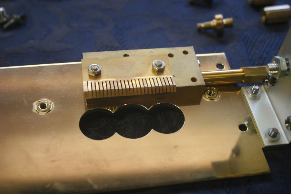
The contact fingers for the vane capacitor.
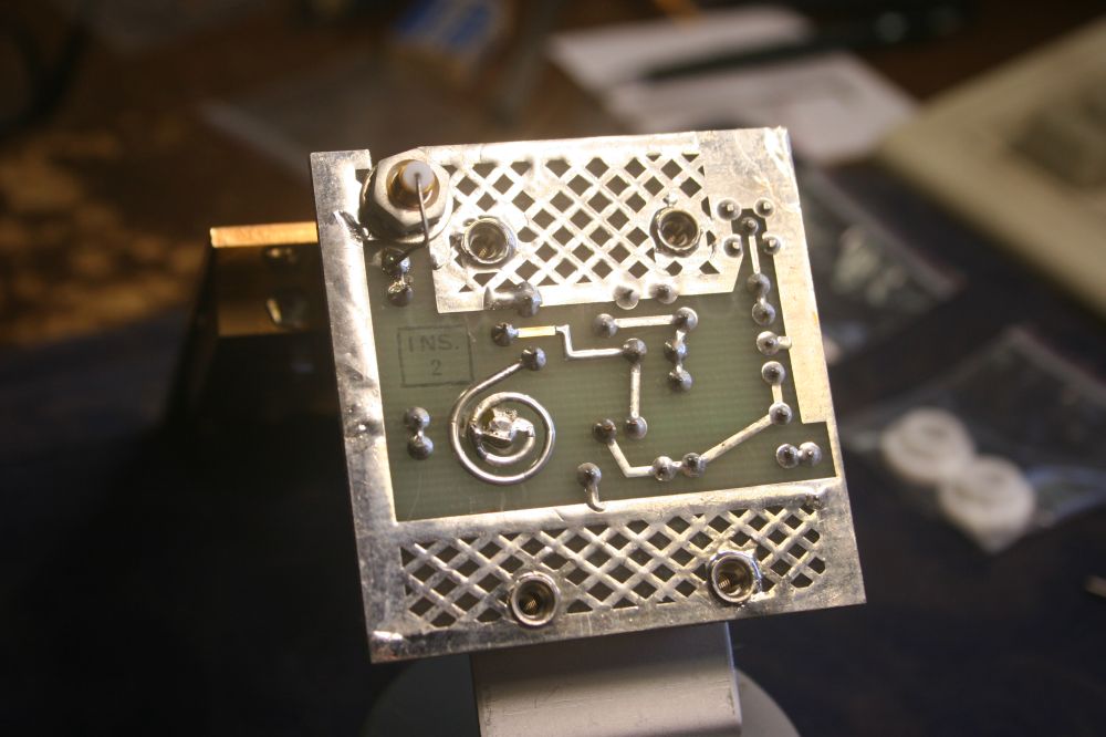
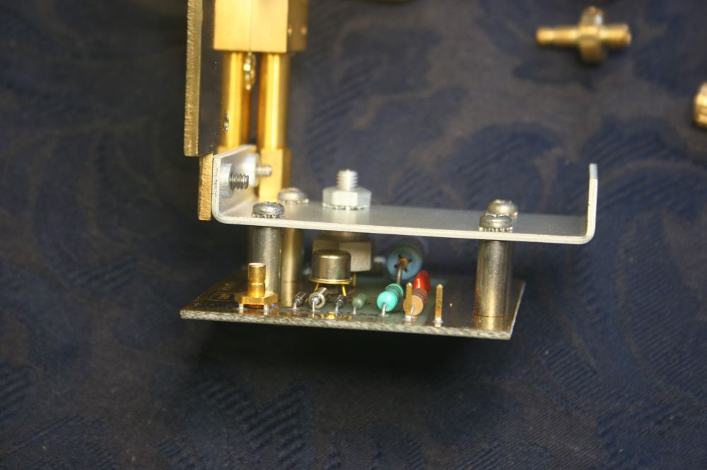
Tracks on the current detector amplifier PCB. Note the 'factory set adjustment' of the small inductor formed by the trace spiral.
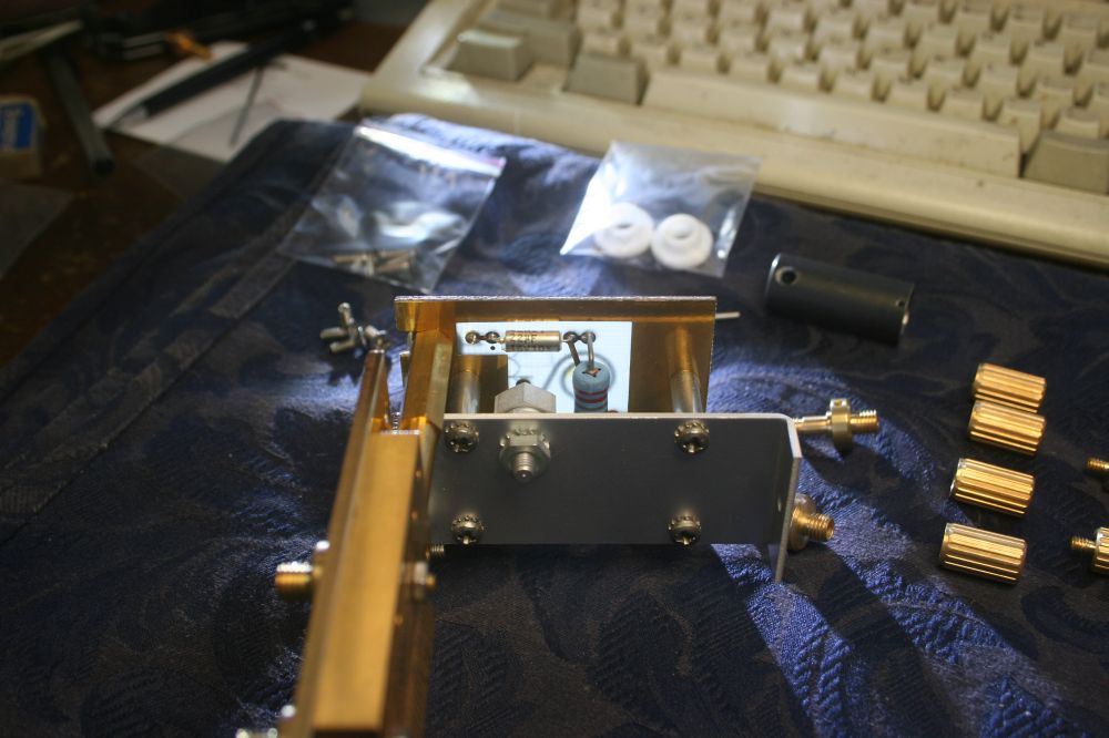
Final stage of assembly. Tightening the posts with the base plate fitted over the teflon insulators. Then the base plate has to be removed again, to allow tightening the locking grub screws on a couple of the posts.
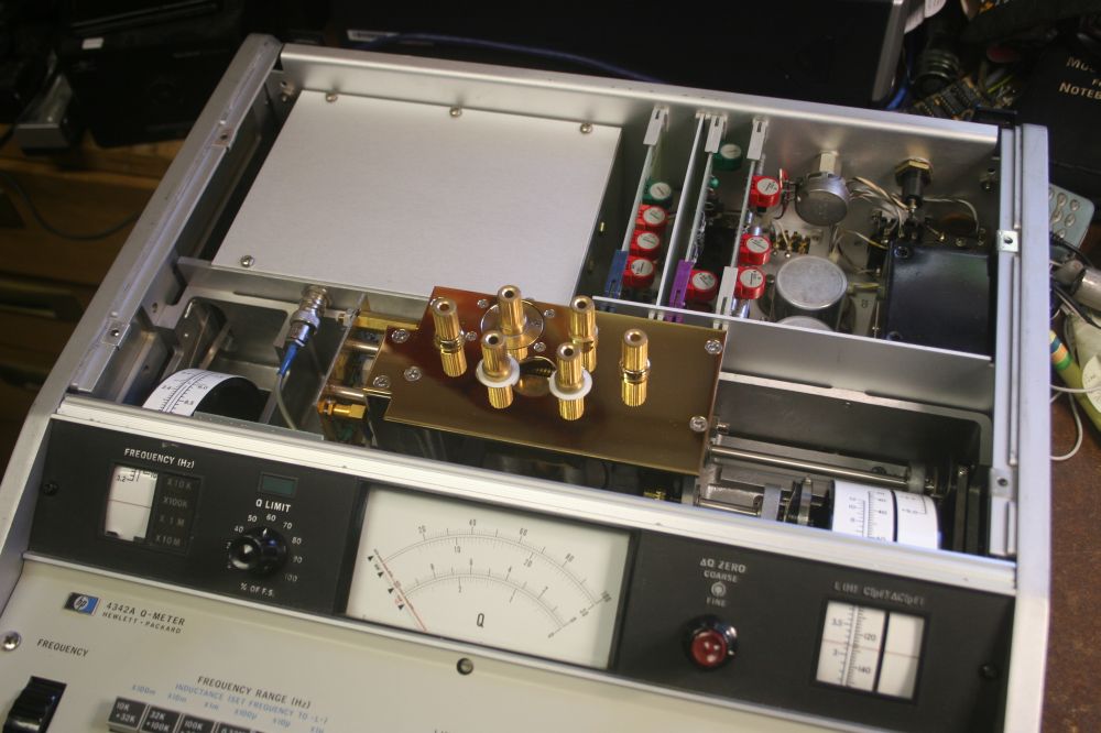
Done!
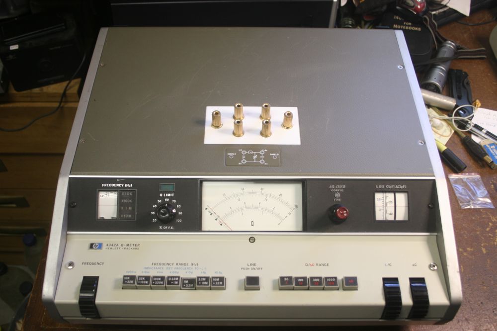
Now to buy an original operation and service manual, then find out if the Q-meter is actually working and calibrated.
Hopefully...