Making a Mill Bed Skirt
20111213 TerraHertz http://everist.org
When you have a cobbled together hobby workshop, made of shoe strings, old fence posts, improvised tools and a few termites for luck, the path from A to B can sometimes go via C, D and Z. Project planning is something they do in other places, on projects they have done fifteen times before. In my little joke of a workshop, almost everything I attempt is unknown ground (for me) and usually involves quite a few surprises.
Currently I'm trying to design and build some quite ambitious double swing doors for my future sculpture workshop. They're unusual doors. For one thing they are huge - the opening is 2.7m wide by 2.6m high. I want to keep the top two thirds of the door area open to light, ie made of glass with as narrow frame edges as possible. But the doors also need to be as soundproof as possible when closed, so the glass must be thick, preferably even double layer. Because the doors are so large, for safety and strength the glass has to be laminated. These doors will be very heavy.
But there's one more real design challenge. The doors swing outwards, have to swing 180 degrees to lay right back against the walls, aaaannd... because of sloping ground outside the structure that isn't practical or desirable to reprofile, one of the doors has to rise up as it swings out, to clear the rising ground profile.
All this makes for some pretty unusual requirements for the hinges. Oh, and they have to be seriously burglar deterring too, despite having the hinge pivot exposed on the outside. Plus they have to be permanently weatherproof — no rust allowed.
The eventual design involves extruded aluminium rectangular sections for the door frames, and custom-built hinges — made of welded stainless steel components. My MIG welder can handle stainless fairly well, I know from experience. And so I began to make the hinges.
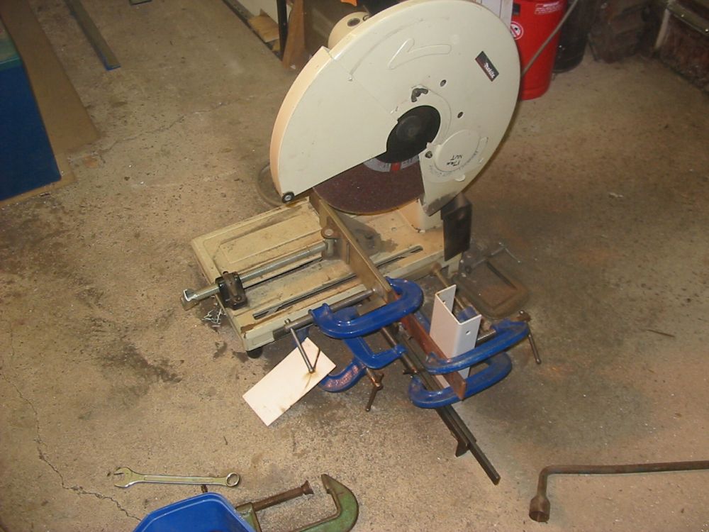
Cutting the flanges for the hinges. That's a big bar of 316 stainless steel, ready to cut. The thing attached to the disk cutting machine is an adjustable end stop I'd made a while ago, plus some improvised clamping to hold the cut-off piece of bar in place through the entire cut.
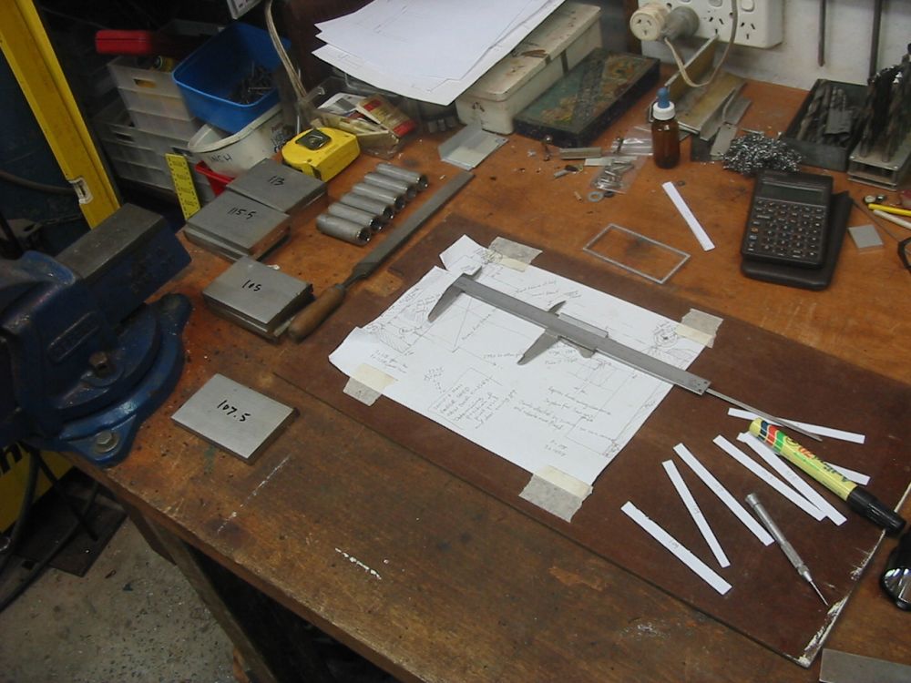
Most of the stainless hinge parts, rough-cut. There will be six hinges, three to each door. Still needed to do some more of the tube pieces, and the pins. The drawing is a full-size dummy of the two door frames layout, for direct measurement of dimensions.
Next step is to true-up the ends of the stainless bar pieces, since grinding disk cut-off tools are far from precise.
For hinges they need to be perfectly square, and correct lengths. But how? Stainless steel isn't exactly easy to work with. The only feasible way (for me) is to mill them. I do have a (toy-like) milling machine, but for stainless it's absolutely essential to run coolant fluid over the cutting bit. Otherwise it heats up and loses the temper of the cutting edge. Attempting to machine-cut stainless steel without coolant is a near-instant way to ruin cutting tools.
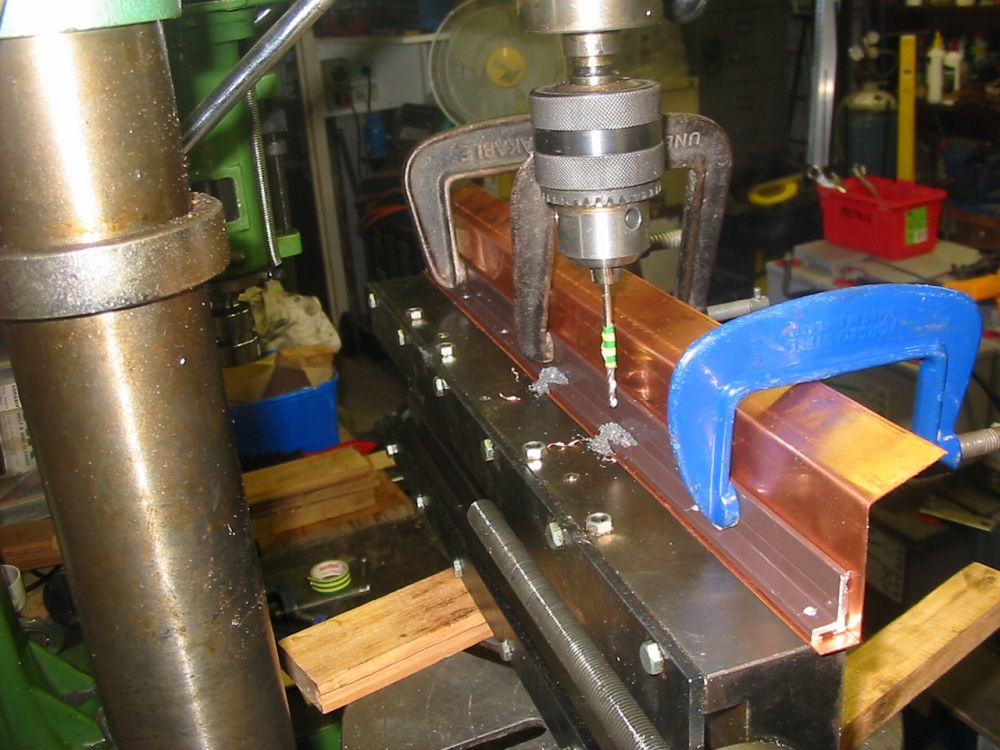
But my mill has no coolant fluid setup. So between that last pic and this next one, I'd bought and installed a cutting fluid system on the mill. Sidetrack number one. Rather improvised as you can see.
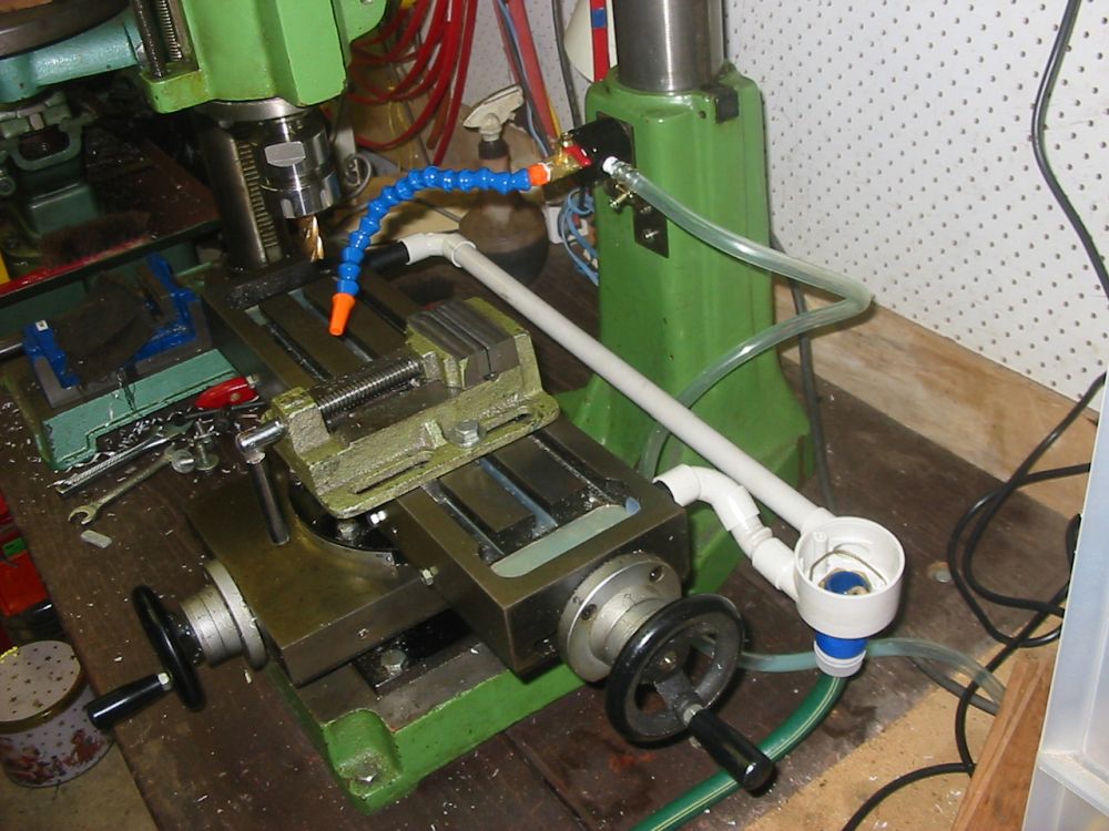
The flexible nozzle tube (blue with orange tip) is attached to the mill with a magnetic base, so it can be easily moved around. This milling machine had only token facility for installing a fluid loop. Just two unthreaded outlet holes from the mill bed. After some futzing around I found a combination of tubing and pipework that would press-fit hold together. That's the gray tubing and repurposed junction box. Draining to a garden hose via a clip-on hose fitting. In this simple form it worked, so long as the nozzle was oriented to ensure all the fluid flowed down into the bed slots. I had a feeling that wasn't going to be very practical.
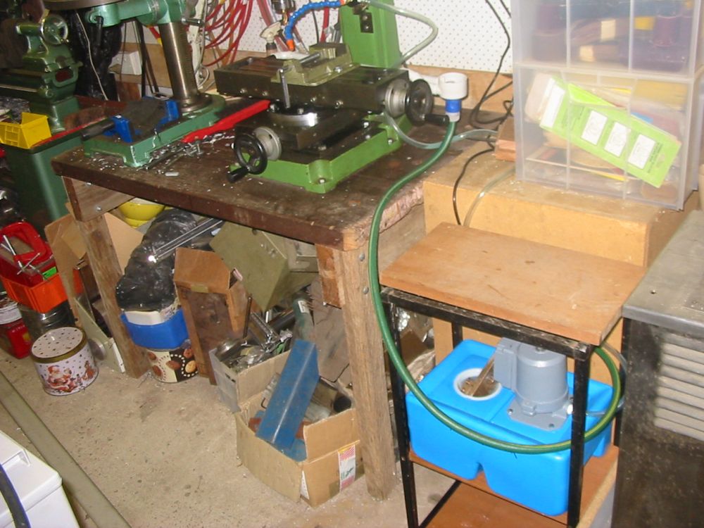
Just to show the cutting fluid tank and pump. It recirculates.
You thought I was joking about old fenceposts, didn't you? Nope, that bench under the mill and drill press is actually made of old hardwood fenceposts, and some wooden stair step boards. The junk piled under the table is made entirely of junk.
So then I tried some test cuts.
I hadn't really been planning on writing this up, since I didn't know it would get so complicated. So there's a bit of a gap in the record here. You can guess what happened with the test cuts, right? Yeah, cutting fluid everywhere. Some going back to the pump tank via the pipes, but most going on the bench.
That's why real milling machines have wide gutter-like upturned skirts around the edge of the bed, to prevent just that. The cutting fluid is not very nice stuff, and getting it on your hands, bench, floor, etc is undesirable. It also turns out to have the most amazing power to rapidly disintegrate particle board I've ever seen. Something to do with being a mix of water and a penetrating solvent. Nearly instant decomposition, literally while you watch. And that cabinet to the right of the mill bench is a sound damping enclosure for a small air compressor, and is made of particle board, unpainted. Why did I never paint it? I don't remember. Stupid me. Now it has one corner sort of 'dissolved'.
Anyway, it was immediately regretable, and imediately obvious that my toy mill needed a not-so-toy liquid-catching skirt around the bed, or this wasn't going to work. At all.
Ah. OK, how am I going to do that? Err...
After quite a bit of dithering, I decided to use some thick copper sheet I had leftover from a shower base in-wall damp barrier construction.
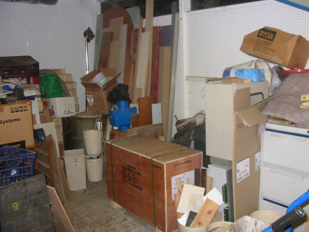
To make the necessary neat folds... Hmmm. I'd have to dig my brand new, never used sheet metal folder and guilotine out of storage. I'd bought it over a year before, and planned to set it up in the sculpture workshop when that reached lockup stage. Trying to avoid the decision to get it out now, and set it up in the machine shop where there really wasn't room, was part of the reason for dithering. Such a lot of effort. The pic above is of the folder/guilotine transport crate, after I'd unburried it from a heap in the unfinished sculpture workshop. Which currently serves as a disorganized general dumping ground.
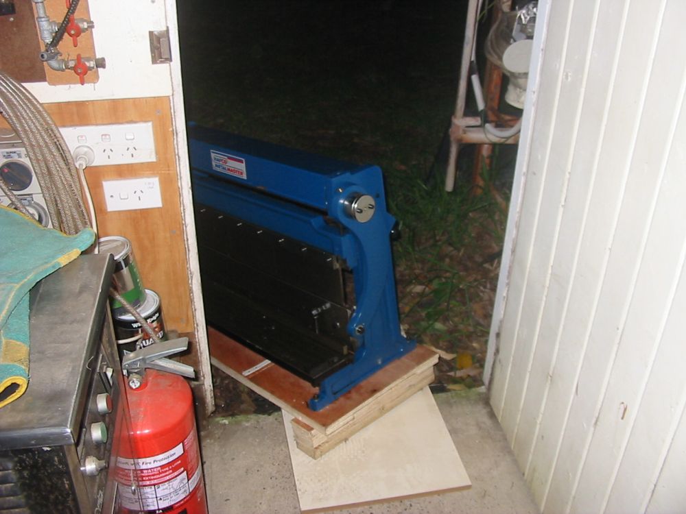
After de-crating it, there's still the problem of moving it around. No way can I lift it. I can only just move it around on a trolley on flat surfaces. Pulling it up small steps - not a chance. That's what ramps are for, as seen here.
I wasn't terribly pleased about how far removed this was getting from hinge-making. All I wanted to do was make some simple hinges, and already I'm several layers removed from that task. So I didn't take any pics of setting up the sheet metal folder.
But as you'll see...
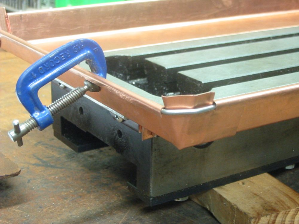
The sheet metal folder at least works fine, the way it's supposed to. Here's one folded copper sheet having mounting holes drilled in it and the mill bed. The clamping is arranged to get the top of the copper skirt exactly flush with the top of the bed.
The same drilling seen from the other side. The brown powder coated aluminium section is cut from leftovers from when I built a screened patio enclosure at my mum's place a while ago.
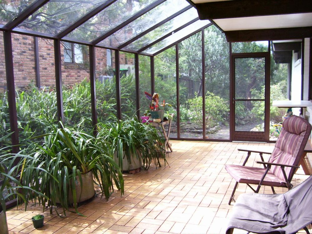
This patio screening. So, at least all these side tracks so far were not costing me anything but time.
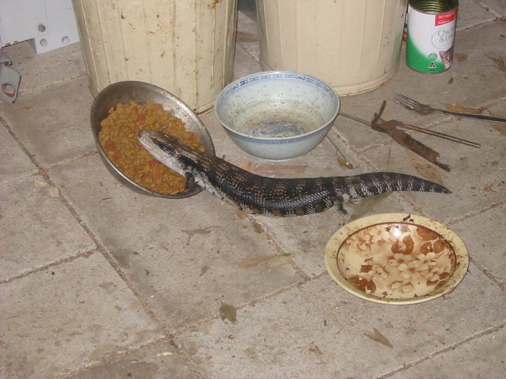
Since the theme is sidetracks, here's a photo-sidetrack. This bluetongue lizard lives around my unfinished sculpture workshop, and raids the cat biscuits bowl when he (or she) thinks no one is looking. It's cute, and harmless, and if I could tell him it was OK to take the biscuits I would.
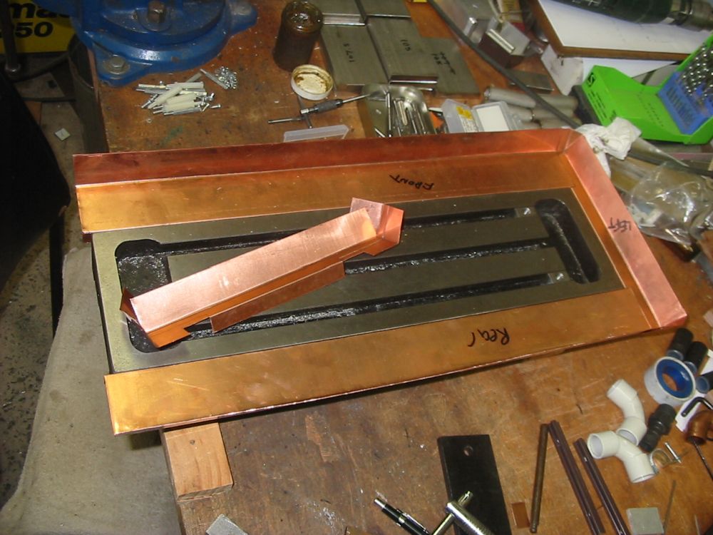
Progress. It's starting to look like this will work as planned, rather than blow out into yet another layer of sidetrack due to finding something else I'd planned to do but then found I didn't have the means to do it.
All the tricky folds are in the small end pieces. It's planned that way so that if I stuff something up, I can just do a new one without wasting too much copper sheet.
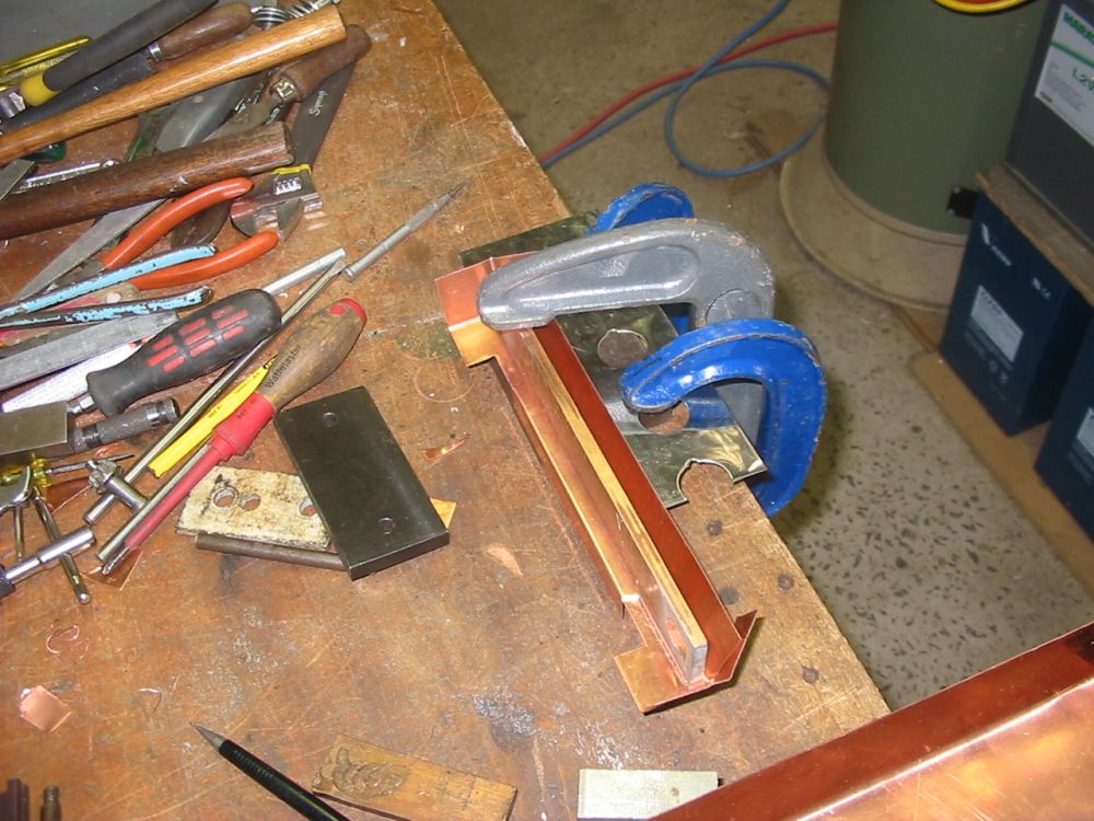
Beating the stepped lip for overlap with the long side pieces. You can't see it here but there are layers of steel shims under the copper, to produce that sharp lip on the step.
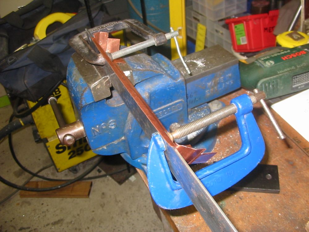
The upper rim of the skirt needs a U-shaped fold, to accept a stiff wire rim. This is how to make that U shape, using a strip of iron the right thickness and with a rounded edge. It's clamped to the copper, then the sheet is progressively beaten over the lip with a small hammer, working back and forth in small degrees of incremental bend, so as to not stretch the copper much.
With everything assembled, the wire (stainless steel TIG welding rod) is bent to fit and slipped into the copper lip. Then the lip is turned further in to lock the wire in place. Small tabs on corners of the skirt are beaten over the wire using just the stiffness of the wire to form the edge.
Once the edge wire is solidly in place, all the seams of the four skirt sections are soldered and brushed flat while molten.
The lip wire was also soldered in, for extra rigidity. After it's all soldered it's rigid and can be unscrewed from the bed.
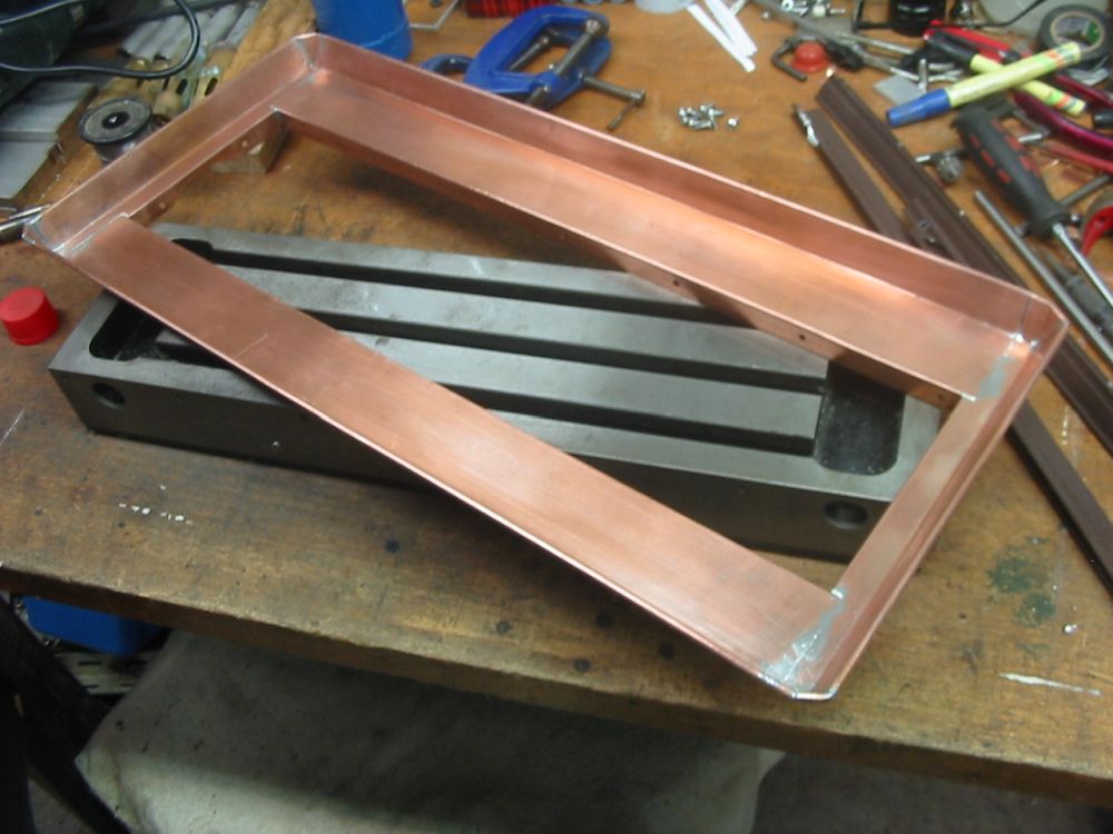
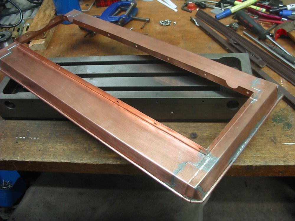
Top view, the completed skirt. I've always loved working in copper. It's such a beautiful and easily workable metal.
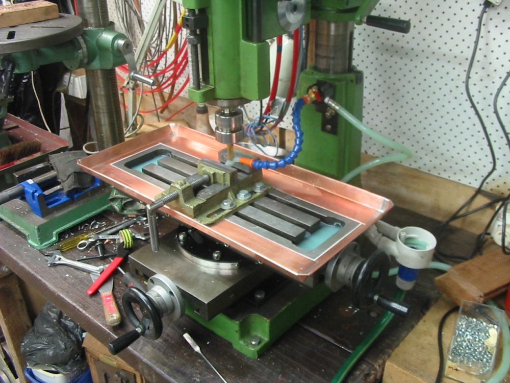
Cutting fluid, Take Two. After reattaching the skirt with a silicone rubber watertight seal in the joints the whole thing works like it should — no more fluid spills.
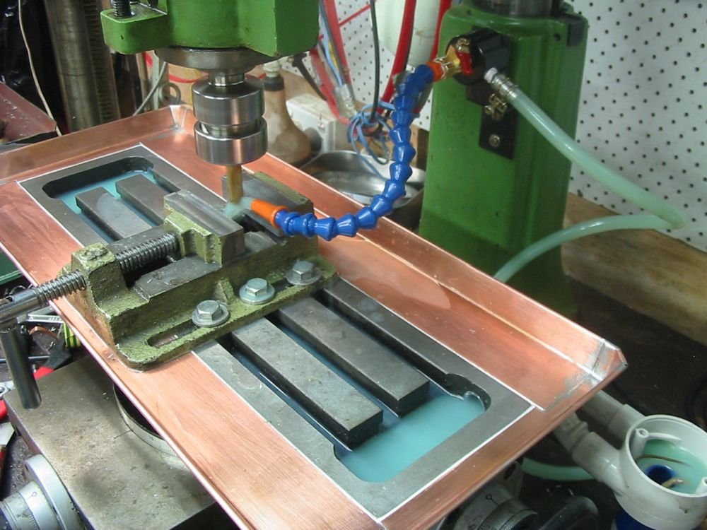
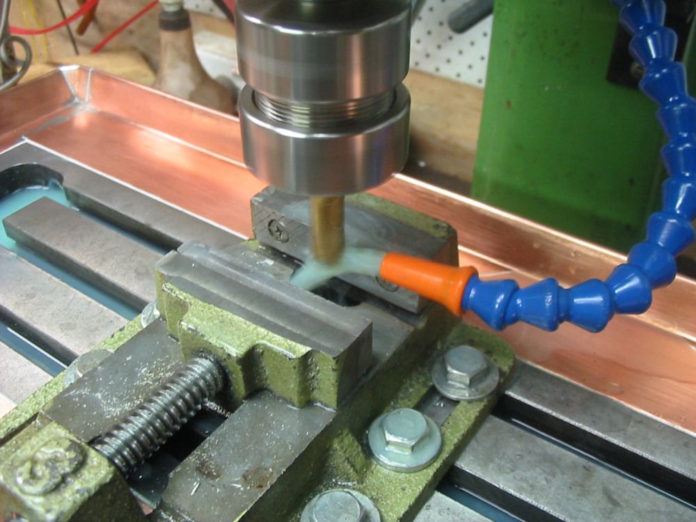
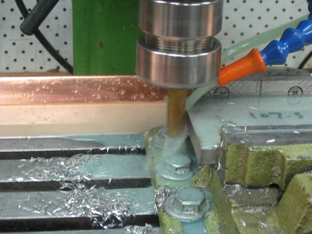
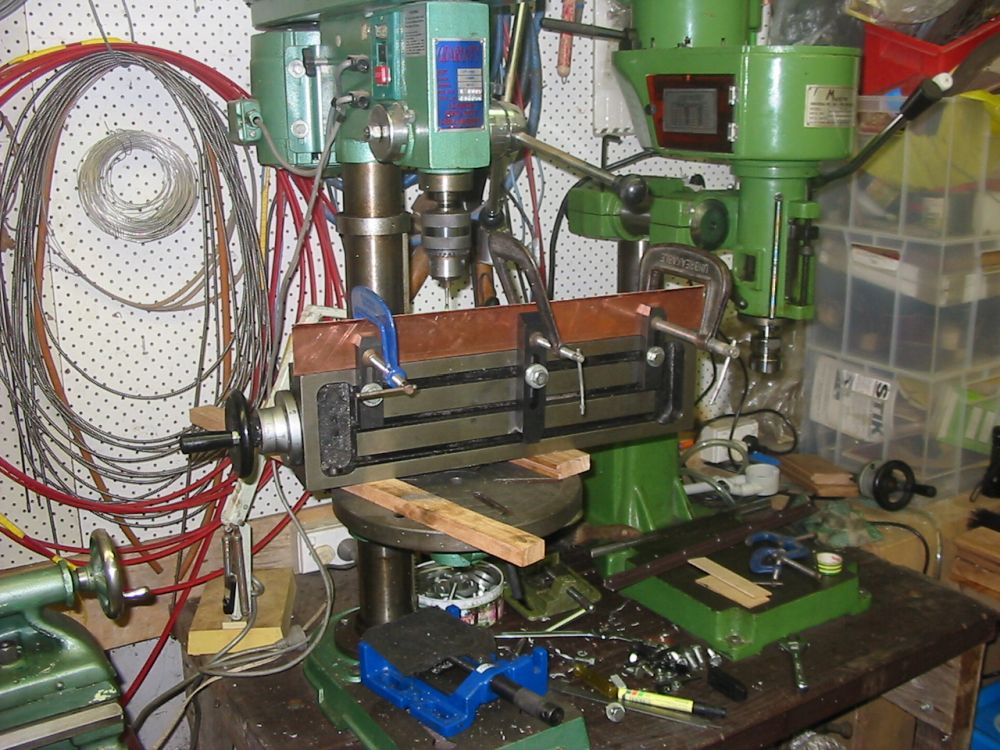
Finally! Back to the hinges and an actual final cut. It works great! This is actually a big achievement for me, as I've never before had the facility to machine stainless steel. Now I can.
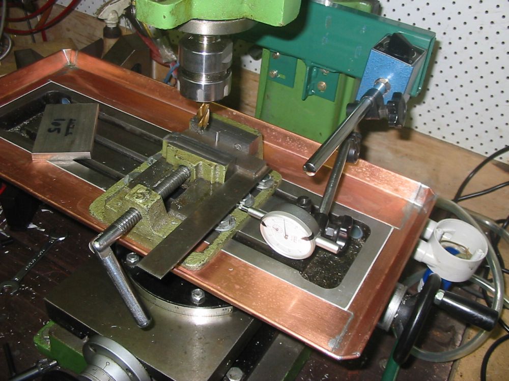
Checking the trueness of the vice face to the X-Y axis of the mill. Since I'd had it all apart during the sidetracks.
Notice anything else?
Yes, another sidetrack. I'd become dissatisfied with the magnetic clamping arrangement for the fluid nozzle, and so added a platform for attachment of magnet based things.
That all went fairly well, considering. What I didn't know then was that the whole hinges thing would turn into a long-lasting wedged dilema. But that's another story.
Update 20150712
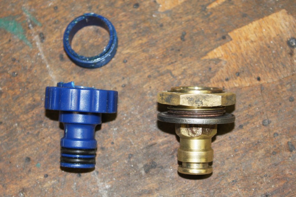
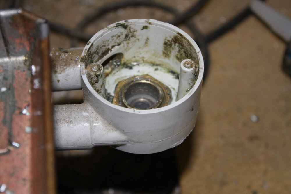
Recently while I was milling the end blocks for a camera mount, suddenly there was cutting fluid pouring onto the chipboard cabinet next to the mill. The plastic hose attachment for the fluid drain had snapped off.
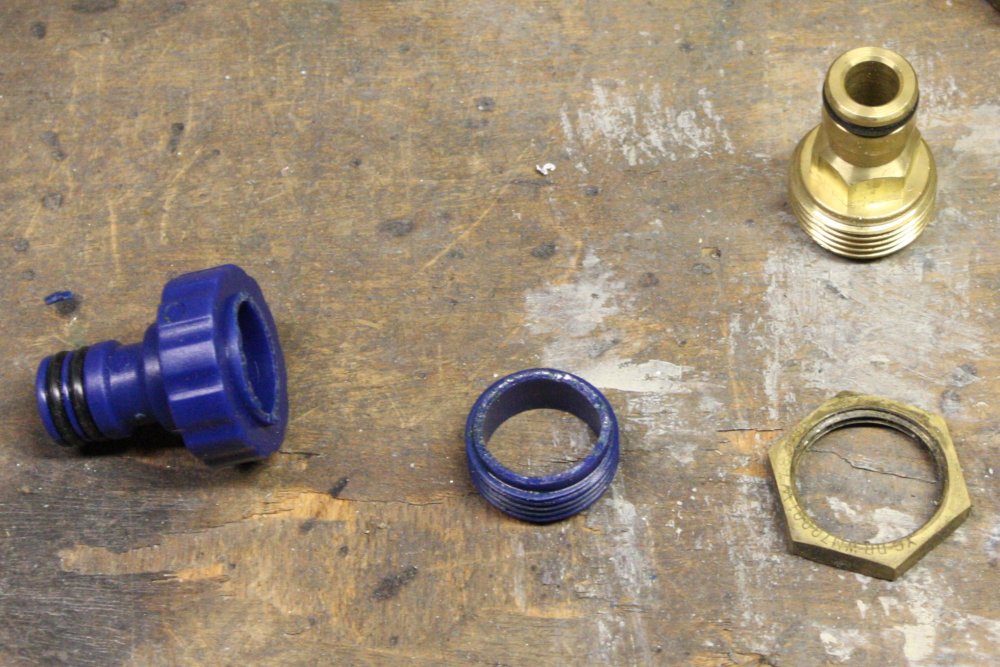
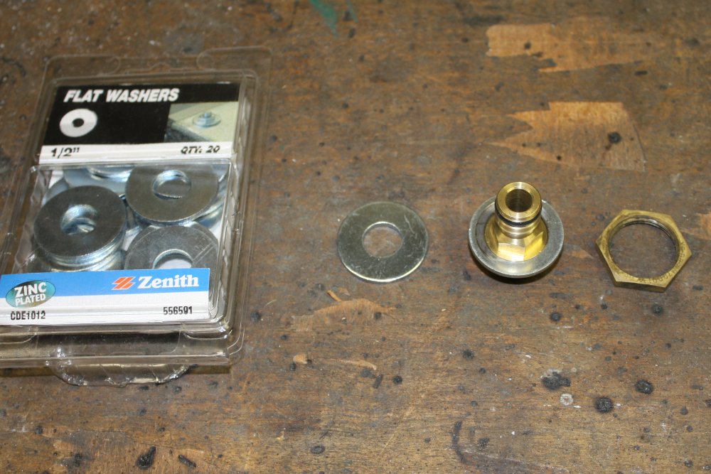
The replacement had better be metal. At top right is the brass garden hose part I'll start with.
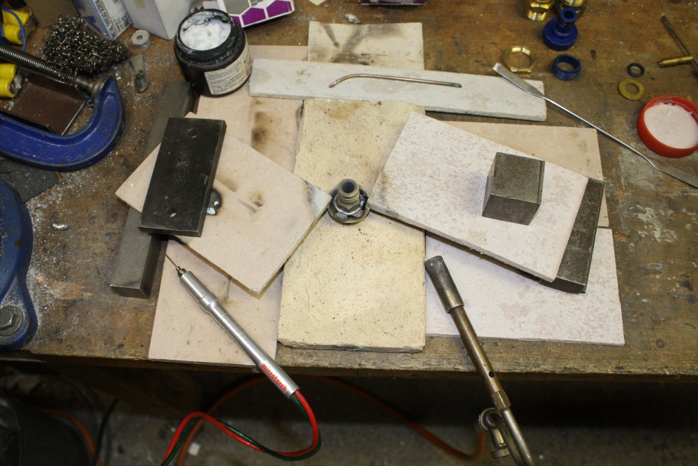
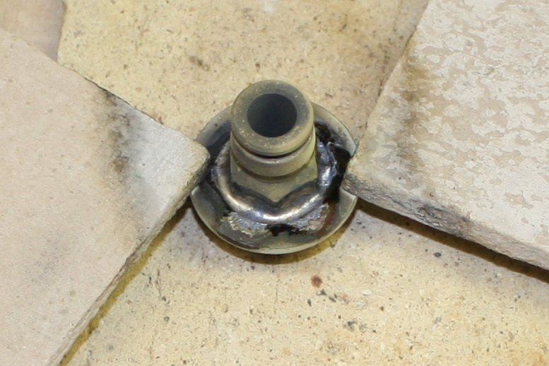
Easy. I bored out the center of a large steel washer to fit the base of that brass hose fitting, then silver-soldered it on. Screwed it into the cutting fluid drain with silastic sealer. Done.