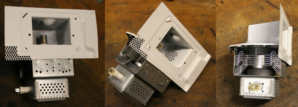
The magnetron and entry waveguide, bare. Ha ha, definitely not to ever be powered up like this!
A while ago a friend gave me a salvaged new-style inverter-based microwave oven, and so this story began.
Previously I'd mentioned to him that I'm interested in the new inverter-based microwave ovens, as they have a lot of potential for electronics hacking. The old transformer ones are very simple and could be used to make regulated HV supplies using triac phase control on the mains into the transformer, but the big HV transformers are very heavy and you'd still need some linear post-regulation. Which at several KV, is a bit of a pain. I've at least two big cardboard boxes full of parts from old transformer microwave ovens, but never worked up the enthusiasm to do anything with them. Wasn't even bothering to salvage tossed old-style ovens from the kerb anymore.
The new ovens however, use a high frequency inverter to generate the HV for the magnetron. The whole power chain is very light and small.
This type has been around for several years, so now and then one already finds an inverter type microwave oven thrown out on the street. It's easy to tell which kind one is — just pick it up. If you go "Oof!" it's the transformer type. If it's very light and feels like an empty box, either someone took all the guts out and it is empty, or it's an inverter type.
I'd found two inverter type ovens so far, but both of them were in such nice condition, and so easily fixed, that I couldn't bear to strip them down to the basics for hacking experimentation. They're both sitting in my workshop 'kitchen', in use as an oven, and well, a backup oven.
The first had a blown drive transistor in the inverter, so that was just a matter of buying a new transistor. When I found the second one I thought OK, now here's one to be hacked. Opened it up, and it turned out there was nothing wrong with it except that the flexible strip connector to the front panel membrane buttons had slipped out of its socket. Plugged it back in and the unit worked perfectly. After that I couldn't bear to tear it down and scrap 80% of it - the case, etc.
Interestingly, although those first two were different Panasonic models with different front panel styling, they both appear to use the same HV inverter PCB. That made me hope the board was going to turn out to be very common. All the better to base a project on.
Then my friend found another street-tossed inverter oven, and gave it to me. It's a Panasonic model NN-SD686S, rated at 1100W.
For a moment I thought I was going to have the same problem - it may turn out to be too nice to rip to pieces. The cabinet is brushed stainless steel, which is a style I quite like. For some reason the previous owner had chosen to leave the thin blue protective plastic film in place, and although it had peeled a little at the edges and so looked very ratty, I was resigning myself to finding the unit might look brand new with a little cleaning and peeling the film off.
No such problem, however. For one thing that 'protective' film was now totally unremovable. It seems the film degrades and gets more fragile over time, while the adhesive gets tougher. By now the adhesive is stronger than the film, so any attempt to peel it just results in the film breaking. Nothing I tried would get it off without scratching the brushed stainless underneath.
So... this machine will always look disgusting. Good! Also, lesson: peel the damned protective film off right after purchase, idiot.
Secondly, it wasn't working. But, it does have that same power inverter PCB again. Yay! Three out of three.
At this point the unit sat on the floor of my workshop, cover off, for about two months. 'Too many projects' is pretty much the rule around here. The microwave would have to wait till there was something else sufficiently horrible I was supposed to be doing, that I'd end up procrastinating over that by looking at the microwave instead.
Well, right now I'm supposed to be fixing four, dammit four of my Tek R7903 scopes that all turned out to have died during a long interval of not using them. All power supply problems. I hate those compact Tek scope power supplies. And I've almost run out of other things to procrastinate with.
So, now to give the microwave some attention.
It powers up, the display and controls work, but pressing 'Start' does not produce any oven-like effects, not even the fan. Then a few seconds later the microprocessor gives up and returns the display to an idle state. No actual information, just 'Nope, not gunna do it'.
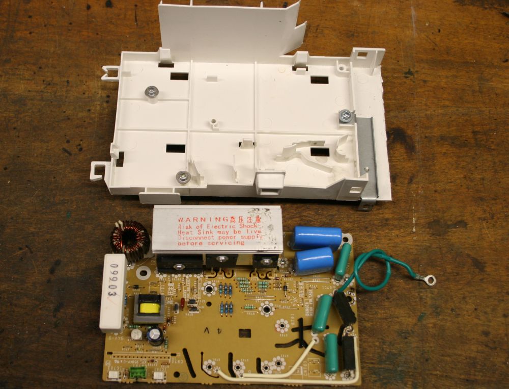
A quick bit of debugging later, it turned out the small relay on the control PCB that passes mains to the power inverter, has an open circuit coil. An easy fix, if I had a substitute relay. But it's too much bother. Or rather, enough of an excuse for me to decide to kill this sucker.
So I stripped the machine down, flattened out the stainless sheet cover for my scrap sheet metal pile, then used a thin cutting disk in an angle grinder to slice the magnetron mount and entry waveguide from the case. Finally cut the rest of the case up very roughly with the angle grinder into flat pieces and dumped in the recycling bin. The glass front from the door went in my glass sheets stock, and the door mesh got put aside for possible future use as a shielding mesh for my vacuum chamber view ports.
And that's when it occurred to me to start taking photos. Oops.
The magnetron and entry waveguide, bare. Ha ha, definitely not to ever be powered up like this!
One amusing side effect of the absence of a very heavy transformer, is that the body of the microwave oven can now be made of extremely thin steel. Since there's no need for the strength required to support the transformer. Most of the oven I just cut up was only 0.5mm thick, including the white paint. It's like paper. That's why the edge of the white-painted steel looks so thin in the photo — it is.
If they make these any more flimsy, the ovens will crumple up if you put anything heavy on top of them.
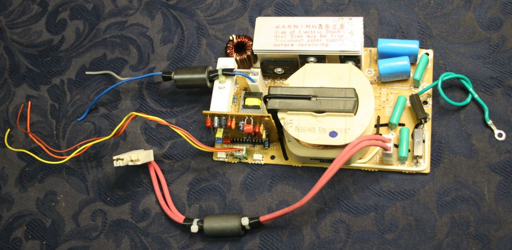
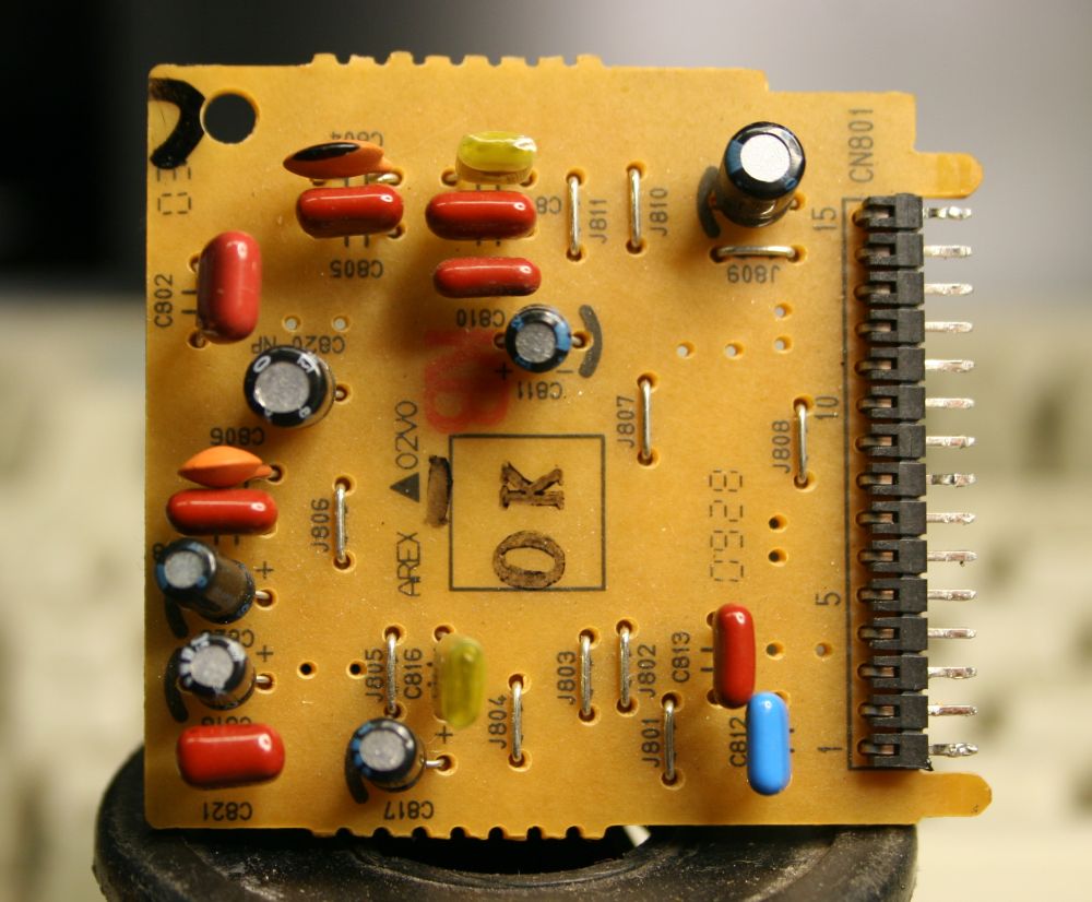
The inverter board. Blu-Gry wires are 240VAC mains in, Yel-Bn-Or wires are control & status logic levels via optoisolators on the inverter PCB, the two fat red wires are the cathode filament HV drive to the magnetron, and Grn is a chassis ground.
I'm hoping the control/status lines are static, as opposed to some fancy serial command protocol. There's just one small IC on the small vertical rider board, and fingers crossed, it's just a plain switch-mode regulator controller.
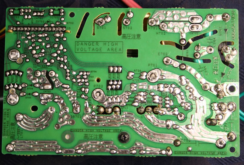
The back of the inverter board. I'd already desoldered the transformer and rider board before sitting them back in temporarily for this photo. So those are not bad solder joints, they are un-soldered joints.
Note the liberal use of cutouts to prevent surface creepage currents between high voltage traces.
The PCB mounts on an insulating molded carrier, which has fins that project up through many of the anti-creepage cutouts. It's pretty clever, I think.
The small rider PCB, which appears to be more or less all the control circuitry for the inverter. Except for...
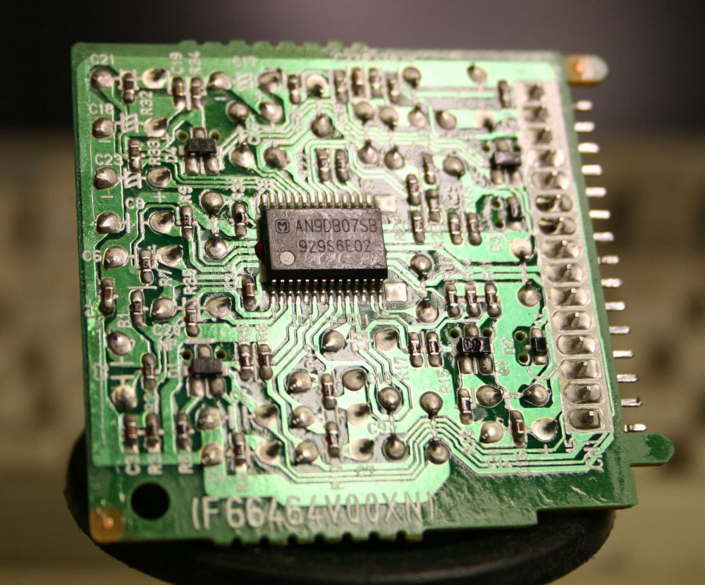
The rest of it, surface mount on the copper side. Most of the work in getting to the point where I can re-purpose the inverter, is going to be in reversing this circuit. The main PCB will be easy; this one will be a bit more effort.
Just for starters, what is that chip? First stabs at net searching for data turn up nothing. I don't even recognise the manufacturer's logo. That's not a good sign.
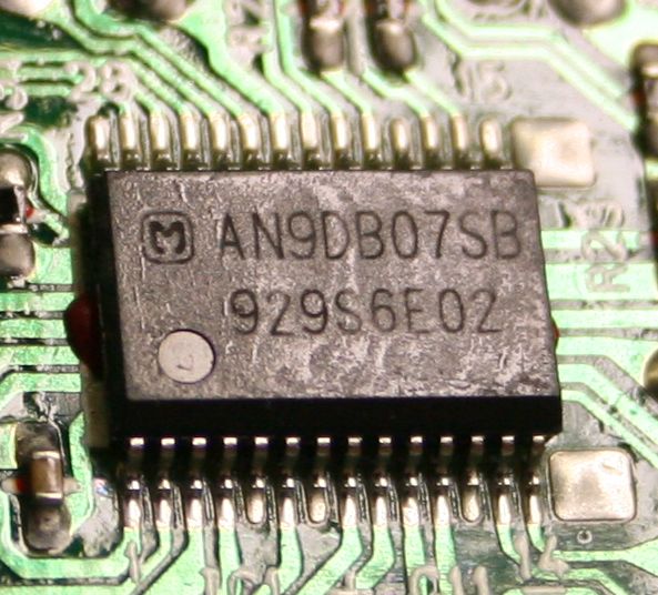
Hello there, where's your data?
Part number AN9DB07SB 929S6E02
Anyone?
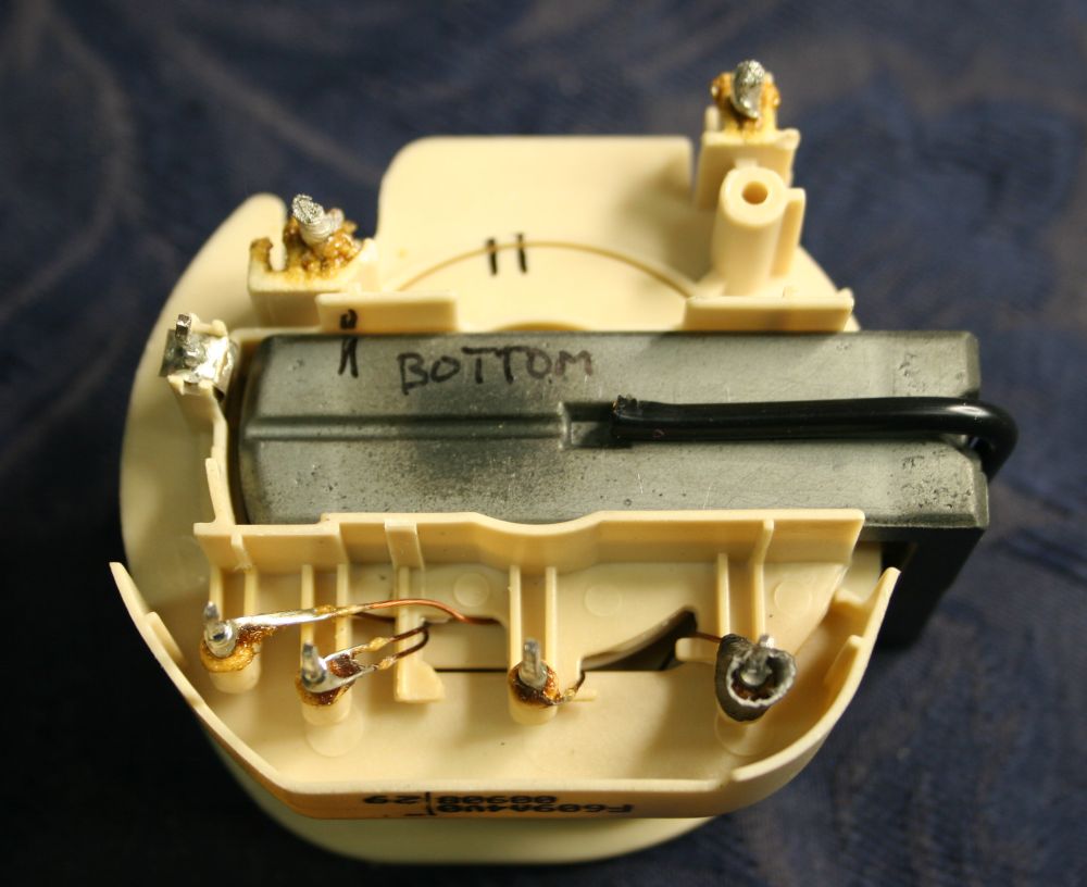
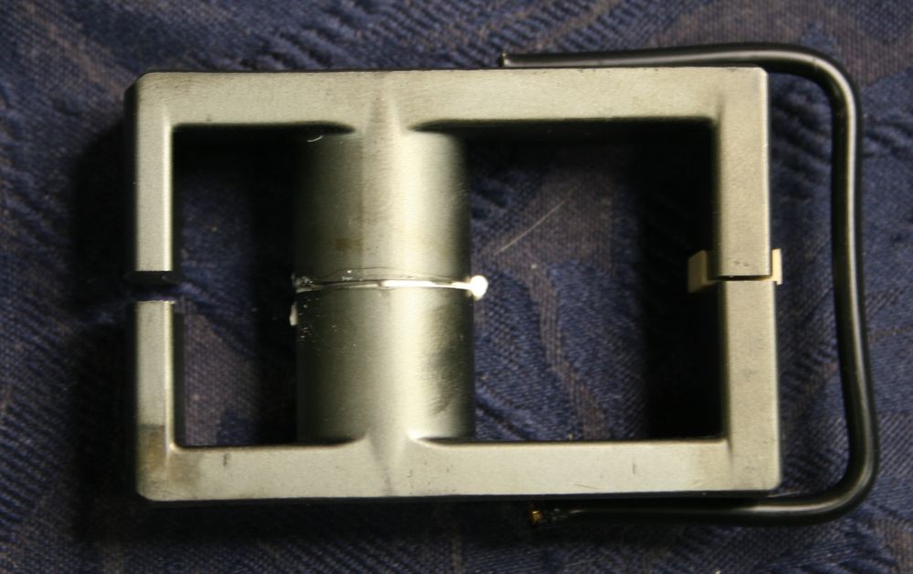
The underside of the inverter transformer. When I was repairing the first microwave oven I found with this board, I'd taken the transformer out from curiosity, and discovered something quite remarkable. Can you spot it?
Not the crappy writing in marker pen, that was me. It's also not the pin at center-left, which is chassis ground and has a small spring contact pressing against the ferrite so it can't develop a static charge. That's neat, but is not the surprise.
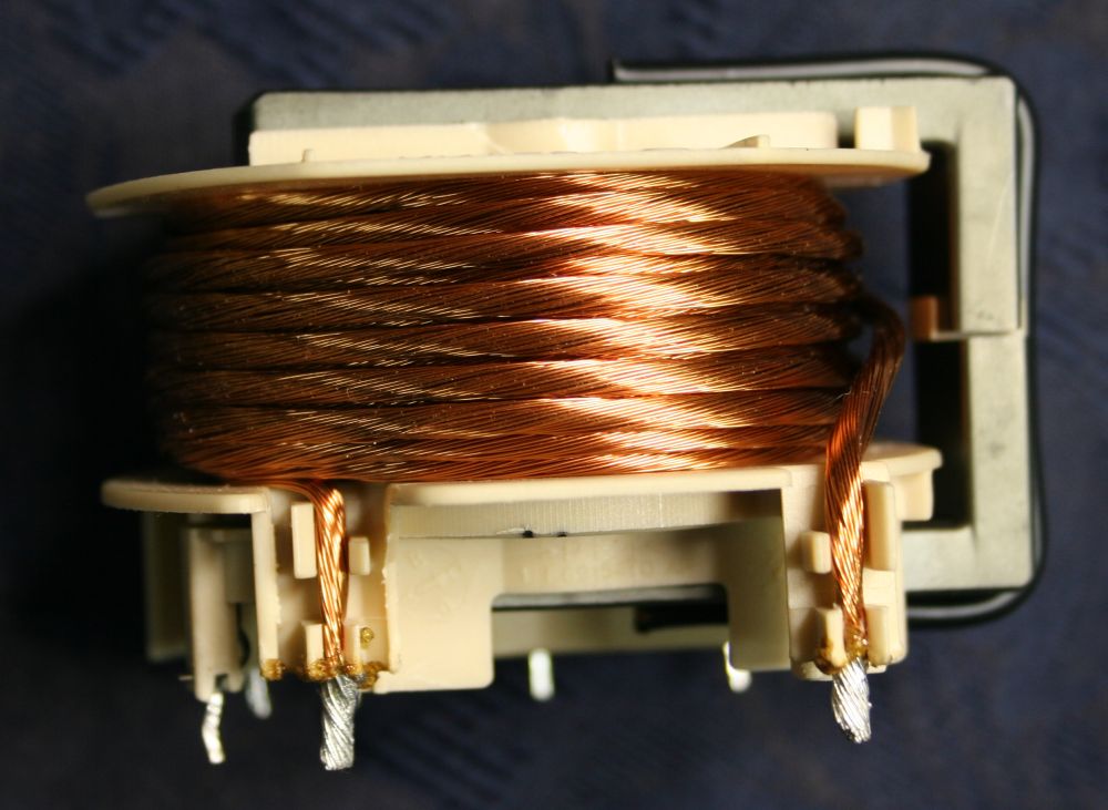
It uses Litz wire, which is nice. This is the primary, which is driven with rectified and HF chopped mains. Also note that the windings are loose, ie not cast in a solid block of epoxy. Which means the primary can be easily modified if desired. Wonderful!
But that's not the remarkable thing either.
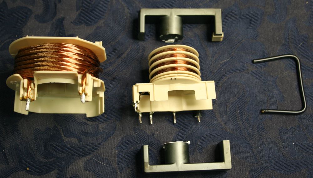
THIS is! The entire transformer comes apart!
Just slide the (non-magnetic) metal spring clip off the ferrite core halves, then carefully pry the cores out. The small gap between the faces in the center of the transformer is filled with fairly soft white material, perhaps a kind of silicone sealer. But it separates fairly easily. It appears to be there more to prevent mechanical vibration than to actually stick the faces together. Don't remove it from the faces, it needs to be there when you reassemble it. Just make sure no loose bits prevent achieving the same ferrite gap as originally present.
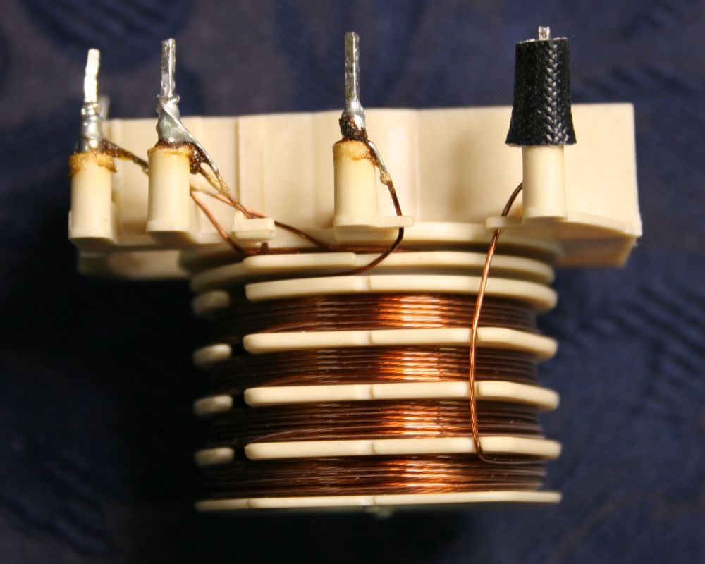
This is the HV secondary. Litz wire again, this time with the strands encased in some clear insulating material. But once again the overall coil is loose, ie still no epoxy potting. There are two independent secondary windings — the many-turns HV winding divided into several sections for reduced parasitic capacitance, and the drive for the magnetron filament, consisting of just one turn of doubled wire.
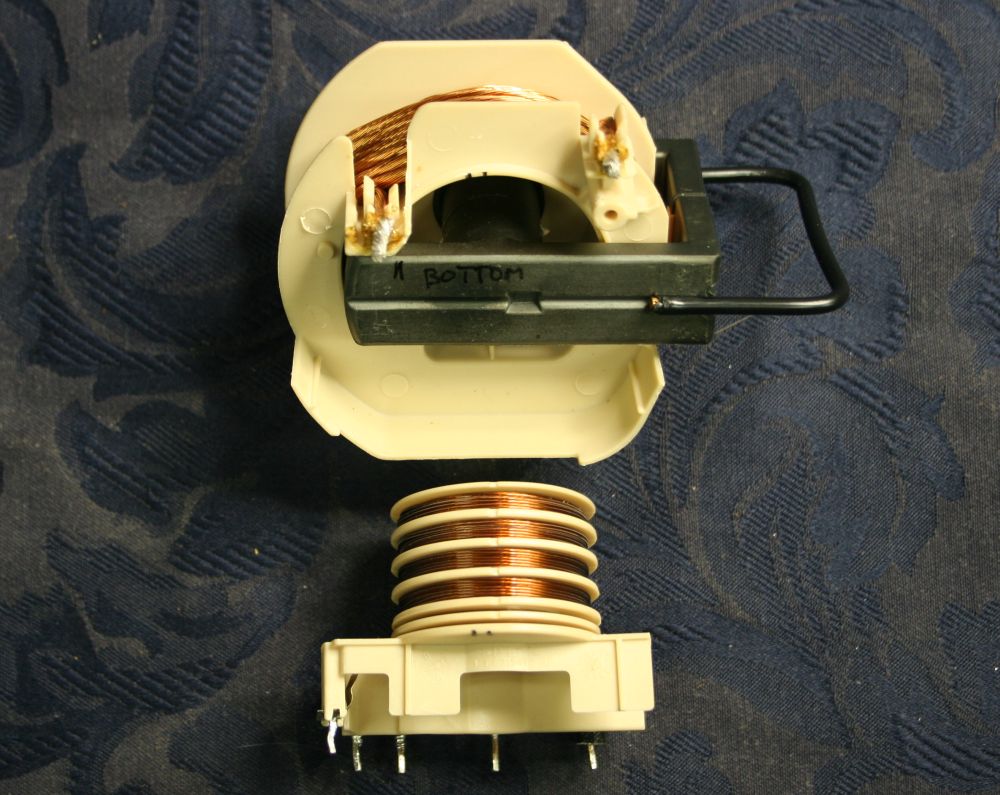
But wait, there's more! Did you notice something funny about the geometry of the ferrite core?
Have another look.
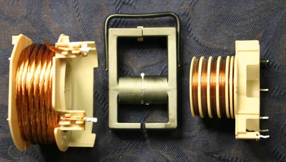
There are two different magnetic field circuits in this thing.
One is normal enough; just like the EHT flyback transformer in a CRT TV set, it's a complete ferrite loop around primary and secondary coils, with a small air gap (the sum of two gaps) to adjust the magnetic permeability down to the desired value, plus diminish saturation effects. That's the 'ring' including the top and center parts of the ferrite in this photo.
But then... there's another 'ring' here, which encloses only the secondary, inner copper windings. It's the center and bottom parts of the ferrite, and has a much larger air gap.
I've never seen that done before. I don't really understand why it's done here, and would very much like to understand.
The effect is... I think... the secondary winding has a greater inductance than the primary, and it's also decoupled from the primary ... um... my head hurts. Does this mean the field can collapse faster in the secondary, without so much affect on the primary?
Probably it's best if I work out which mode this transformer is driven in, before trying to understand the effects of this rather odd magnetic trickery. So that will have to wait till I find data on the control IC. Though I can begin with tracing the main PCB first.
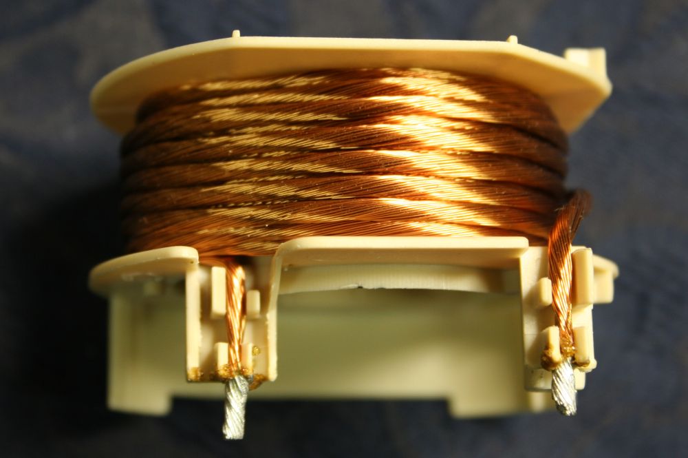
Close up of fiendish magnetic trickery.
Secondary windings. The pin at the right is the 'hot' end of the EHT winding. The sleeve is probably there to inhibit corona discharge from sharp points on the solder joint. On the other side of the PCB, the insulating plastic shield will achieve the same result.
I really admire this high voltage insulated Litz wire. It's very pretty. Wonder where one can buy a roll of it?
One last close up of the primary. It's pretty too.
The whole transformer is very nice. I wonder if the guys that designed this are all open-hardware enthusiasts, and deliberately made something that almost begs to be modified, and easily?
That's all for now. More later, after I've traced the schematics. Assuming I can get data on that IC.
Or... probably I should stop procrastinating, and do something 'useful'.