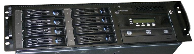
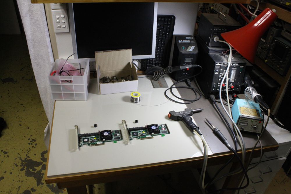
Back in 2013 I was given a very nice rackmount RAID server, with eight 1TB drives.
It has an Areca ARC-1220 8-port PCI-Express SATA RAID controller, which turned out to be completely dead. Bummer.
That's the fatal flaw with RAID disk arrays. So what if they offer safe data retention despite individual disk drive failures? There's still a single point failure mode where the control card dies. And RAID array disks (even RAID-1, ie straight mirroring) always seem to be formatted in a way making them unreadable by anything other than the original controller card. So there's no fallback.
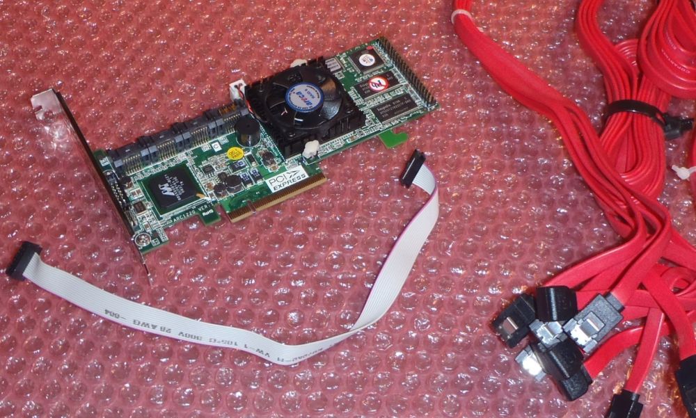 It took a while to find a replacement identical card. Eventually one turned up on ebay, claimed to be working. I bought it.
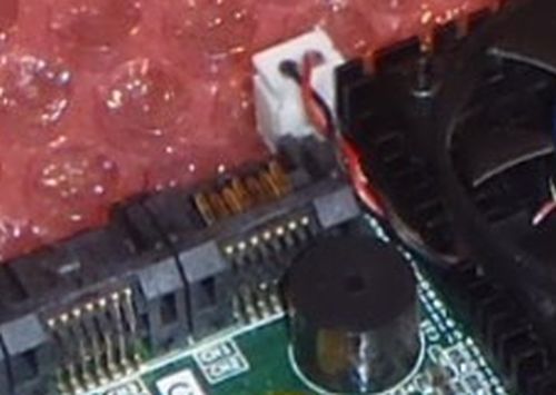
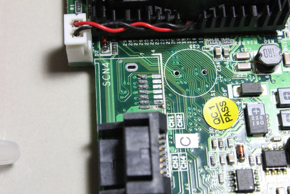
Perhaps I should have examined the seller's picture more closely. Click for larger size. Can you spot the problem?
(Hint: Detail of seller's pic.)
It arrived, and turned out to have one of the SATA connectors broken. Fortunately once you knew what to look for in the seller's listing pics, it could be seen to be broken there. Subtle but clear enough to demand a refund, which I was given. And was also allowed to keep the broken card.
 So now I had two dead cards.
How on Earth did someone manage to break the plastic tab off like that? Anyway, a 7-port RAID card isn't much use when you need an 8-port one.
But the card electronics seem to work, and it's recognized by the system. So how to fix that connector?
The obvious solution was to swap a connector from my dead card to the new one.
Only problem was, the connectors have two rows of surface-mount solder joins to the PCB, and one of the rows is well underneath the connector. Perhaps it was assembled in a vapor phase reflow process? In any case it presents quite an obstacle to hand repair. So I didn't tackle it for a long while, just pushed it down the projects queue.
It finally bubbled up to the top again, and now it's done and works. Here's how. (Discussion at eevblog.)
 |
 |
 |
 |
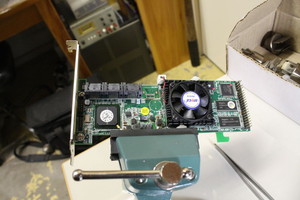 |
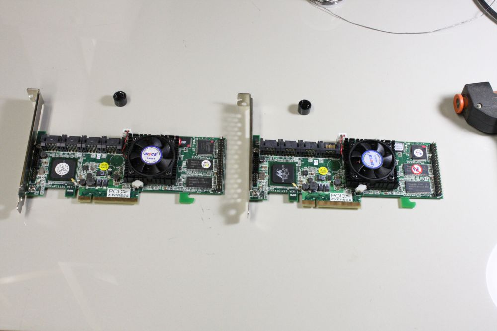
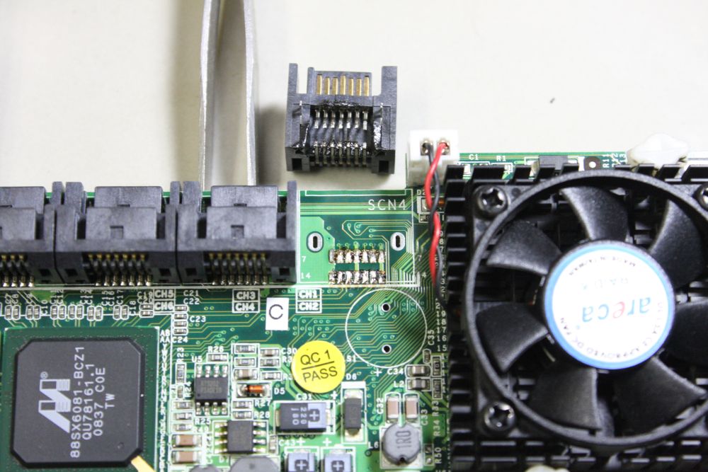
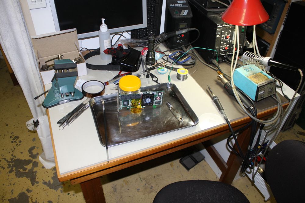
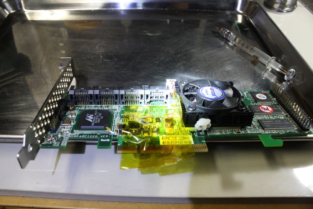
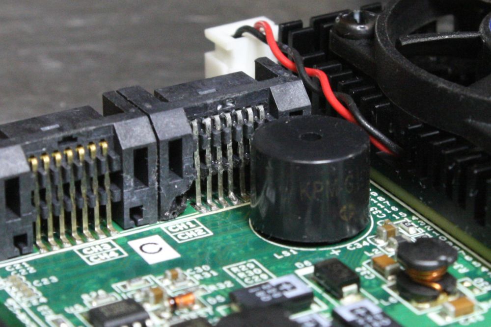
1, 2. Dead card on left, bad connector one on right. First step, remove the piezo buzzers that were in the way. I figured I had four goes at getting a connector off the dead one, in usable condition.
3. First one off, after a LOT of struggle. It didn't go well, and the connector body was too melted and distorted to reuse. Part of the problem is a copper power plane to which two of the pins attach. It sucks a lot of heat and goes under the plastic connector body. How to get it hot enough without completely wrecking the connector? I'd begun with a single small nozzle hot air gun, but that was hopeless.
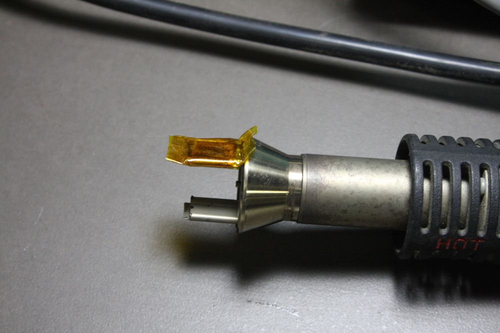
4. I didn't have a single 'wide, flat' air nozzle, but I did have one with two wide flat nozzles. I tried blocking off one with capton tape. (Actually 'coptan' according to the Chinese seller, which is amusing.) That, and turning the air temperature way up, worked.
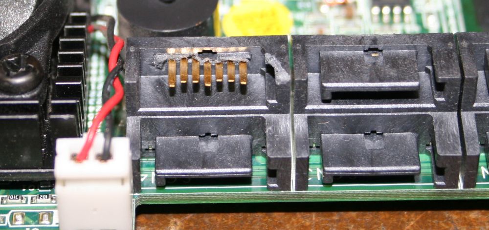
5. First connector removed, showing the ground plane that makes desoldering extra difficult.
 |
 |
 |
 |
 |
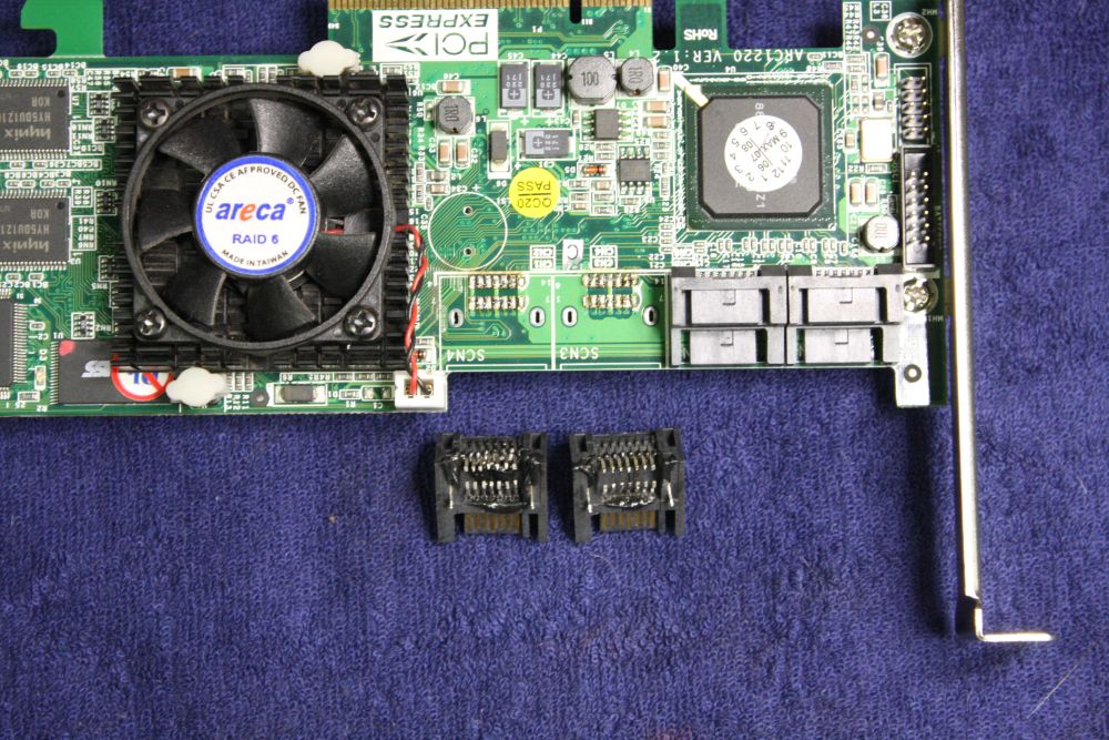
1, 2. First removed connector on the left. Ruined. You can't see, but the SATA connector tabs are distorted.
Second attempt on the right. Hmm... I can work with this.
3. I found I could pull out the pins on the outside row, and get them back in again. Making it possible to solder the inner row of pins with the outer row removed. Yay.
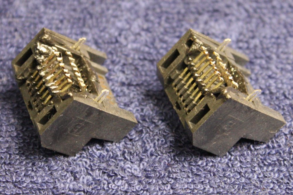
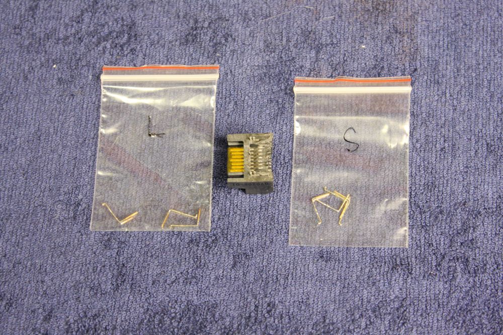
Here all the pins on the back row are pulled out. There are two slightly different lengths; 3 long and 4 short. This is so the three ground pins make contact first when hot-plug inserting SATA. But the length difference is very very tiny, and hard to see by eye with loose pins. It later turned out I'd mixed up two of them. Not the kind of goof one makes twice, but then I hope I never have to do this again.
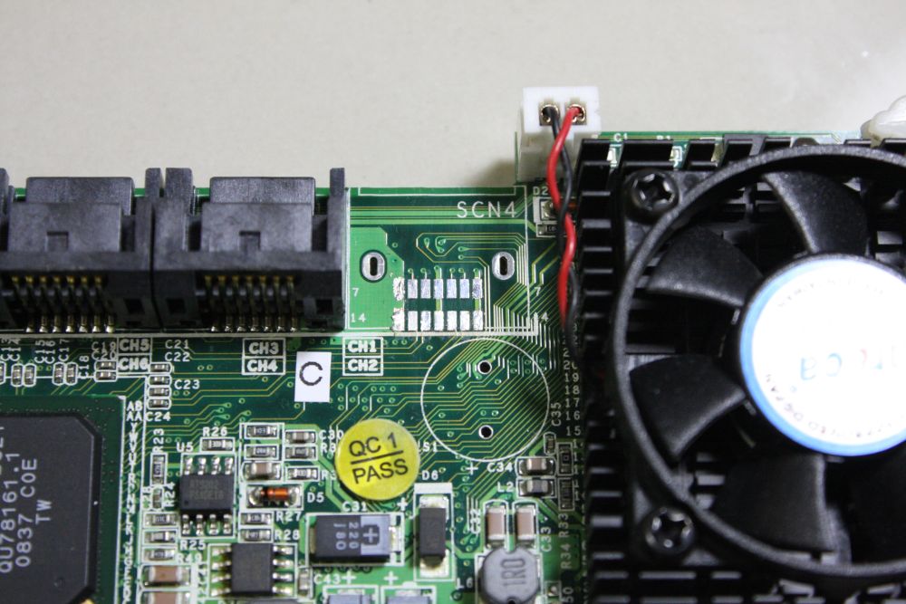
4. The working board, with the broken connector removed, and the usable good connector cleaned up (enough.)
5. After cleaning the PCB pads with solder wick, then trying to solder the connector by hand with soldering iron and solder wire. This failed on the very first pin, where I couldn't do it without bridging pads. Too little room to work in, underneath the connector to get at the inner pins row, without doing more damage to the connector plastic.
I removed it; this photo is before re-cleaning the pads with wick.
Btw, does anyone know who makes these connectors, and where I can buy a few?
I might still be able to get the dead card going, as a spare, if it turns out to be just a lost data fault in the flash ROM.
 |
 |
 |
 |
 |
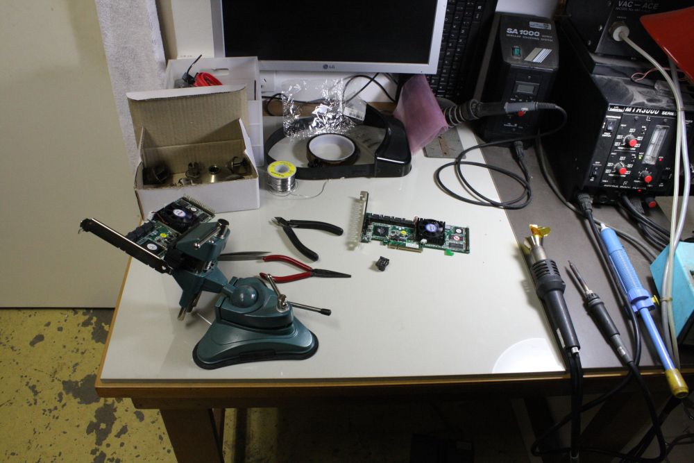
1. An aside. By chance both this RAID server and my current primary PC happen to use the same kind of DRAM, and also allow ECC (error code correction) type. I'd found an ebay seller with 1GB ECC DIMMs of the right kind, going cheap, so had bought enough to fill all 4 slots in both machines. They'd arrived, and here I'm putting them in. They worked. It also involved a bit of education in what utilities are available to actually tell if a system has ECC turned on and working. Enough to satisfy myself that they are, in both machines.
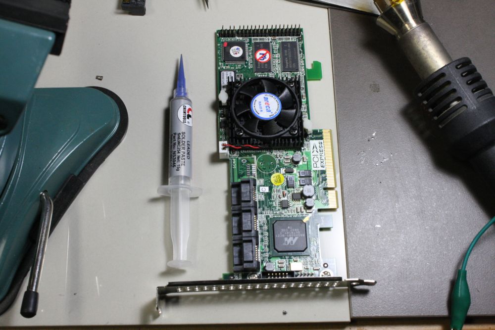
2, 3. Having found I couldn't manually solder the pads in that confined space, I went and bought some solder paste. Not the first time, I just didn't have any atm. Here the paste is applied. It turned out to be quite a bit too much. It's been a while since I used solder paste.
4, 5. What happens when you have too much solder paste, and can't hot-air-jet heat it very well anyway due to the joints being down in a hole with plastic sides? Why, it's a mess. You get hundreds of little solder balls stuck to the board all around the pads. Though, the actual pin to pad joints are OK. But since a lot of the little balls are inaccessible under the plug body, cleaning them out was difficult.
I resorted to blasting them with IPA from the needle of a glass syringe, which worked (gradually.) Trying to avoid washing them into other nooks of the board, like between pins of SMD ICs and under the big BGA chips, I kept the board this way up while spraying it, and stuck on a 'wash skirt' of capton tape. The adhesive of the tape seems to be able to resist IPA well enough. All the IPA squirting done on a metal tray, so I could recover most of the IPA. Lots of room ventilation required!
I cycled between IPA jet soaking, scrubbing with a pointy stiff bristle paint brush, blowing out with compressed air, then trying to peer into the gap under the socket with a binocular inspection microscope (really poor visibility in there.) Finally a little poking with a dental pick, and that row was finished and clean.
 |
 |
1. First three of the outer contacts row back in place. These are the 'long' ones, or were supposed to be.
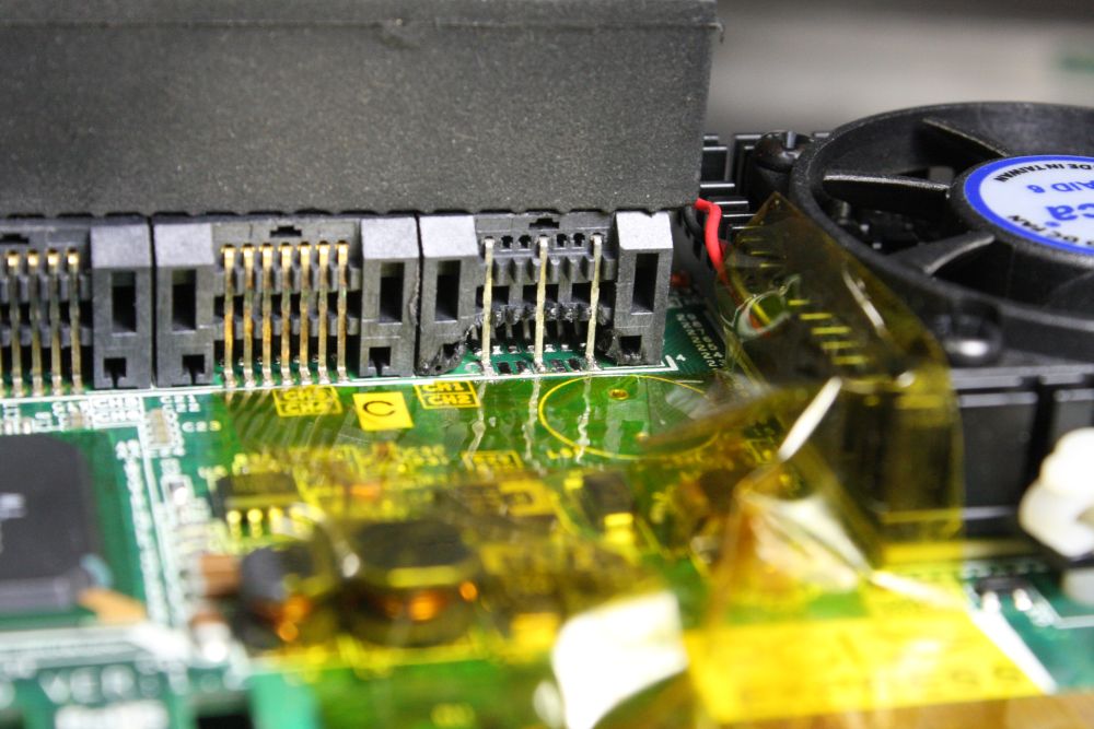
2. All done. Except after soldering all the pins and cleaning off the solder balls (less) from this step, while inspecting under the microscope I'd spotted my mistake with the two swapped long & short pins. You can see it here; 2nd from the left. It's a 'long' pin, and won't go all the way in due to being in a 'short' slot in the plastic.
I decided it didn't matter and it was best to stop pushing my luck with desoldering and soldering on my one working board. It's not like I'll ever be hot-plugging this internal conector.
I added a little super glue since the barbs that held the pins in the plastic originally have lost much of their their grip. After the glue dried I made sure to clean off the contact faces again since superglue can deposit a film on nearby surfaces through evaporation and condensation. And I certainly wouldn't want to create any intermittent problems. I hate intermittent problems.
So then, big moment. Did the board work now? It's had a LOT of handling while doing this, and did I avoid static zapping it, or lodging solder bits between anything?
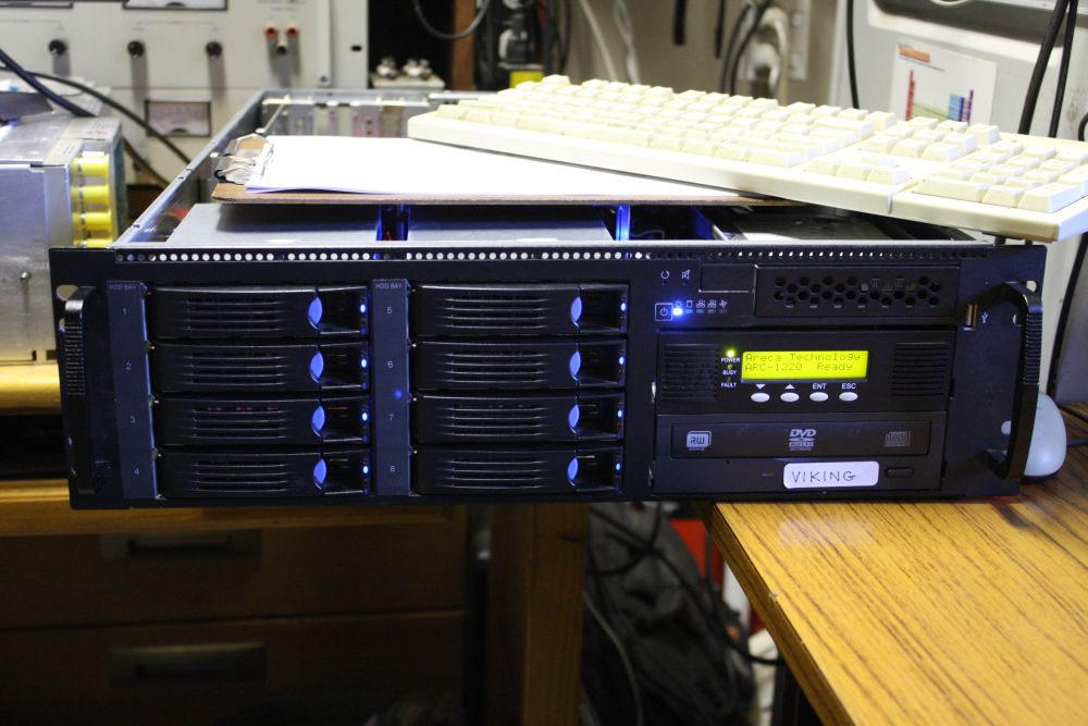
Plugged it in, started the system. The RAID card inserts its initialization stage into the BIOS startup, and it has its own status display, plus good/bad LEDs on the 8 drive trays that it blinks as it evaluates the drives.
It started up, scans the drives (further than I'd had the machine before) then complains there's a problem with drive 3 and 4. "Disconnected"...
Dammit, 3 & 4 are on the SATA connector next to the one I replaced. By this time it was late in the evening. I tried some swapping - drives, cables, the two whole drive bays, and just managed to confuse myself. The problem was intermittent and variable, and I wasn't able to isolate it to a particular module. It didn't seem likely to be the card, but....
Getting depressed, I gave up and went to bed.
Next morning was better. A few more swaps and I was sure the problem was with the left hand bay of 4 drives, and specifically the bottom two slots. But symptoms were variable.
 |
 |
 |
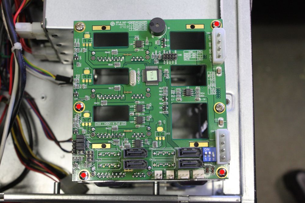 |
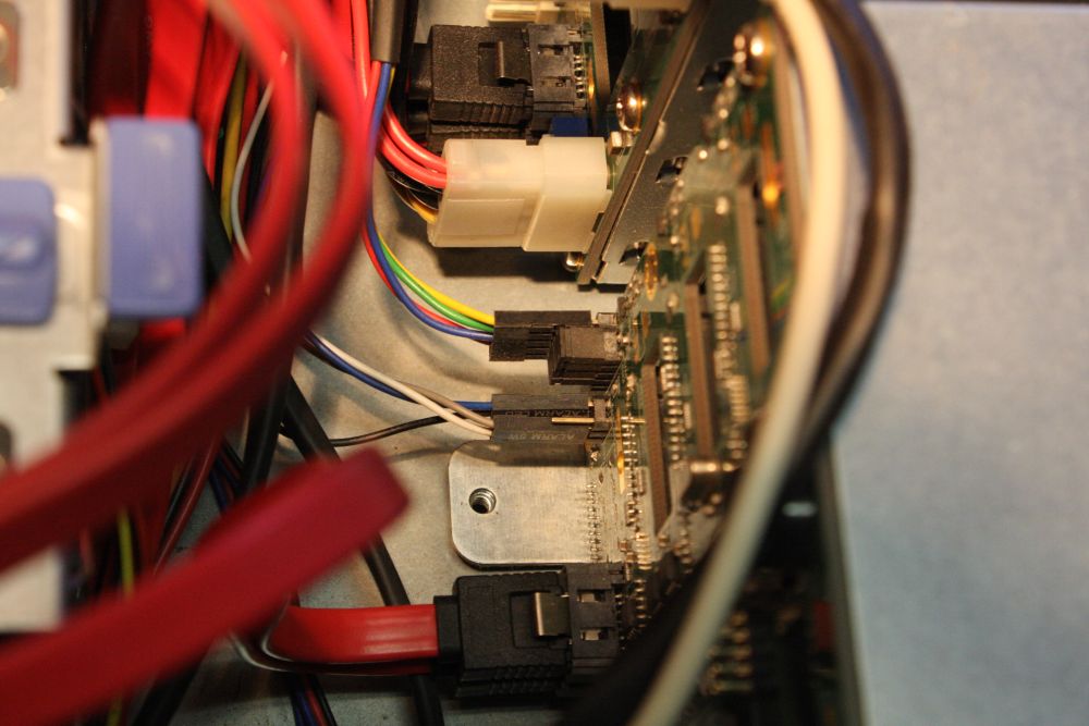
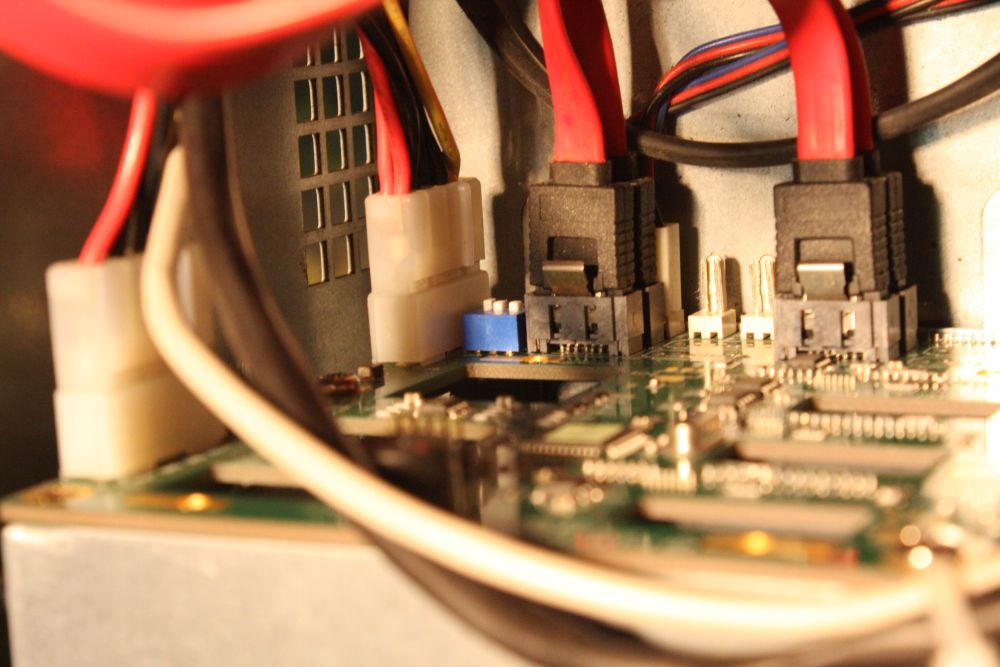
1, 2. I'd need to pull the whole drive bay out, to have a look at the rear PCB for any obvious problem. But first, there are a lot of assorted cables plugged into the rear PCB on the bay, and although I have the Areca pdf manual for the RAID board, I know from experience not to assume any manual will make it clear how all the cables are arranged. So these are a couple of photos I took, looking down the back with the bay still in place.
I'd hoped the problem would be obvious as opposed to some subtle intermittent electronic fault, since there's no way I'm going to find a schematic for this board. But I didn't expect it to be so obvious that I should have spotted it already at this point. Later I realised it's even visible in these photos. Can you see it?
3, 4. And obvious it was. Sometime in this machine's history, someone had removed the 4 screws I've marked in the fullsize pic #4 with red dots. Result: the board flexed enough that the bottom two drive SATA and power connectors made intermittent contact. I replaced the screws, took these photos then reassembled the machine.
 |
 |
 |
 |
 |
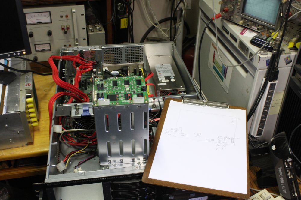
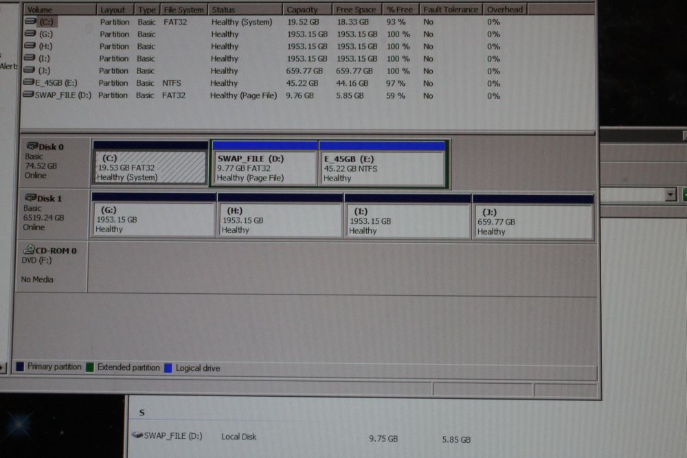
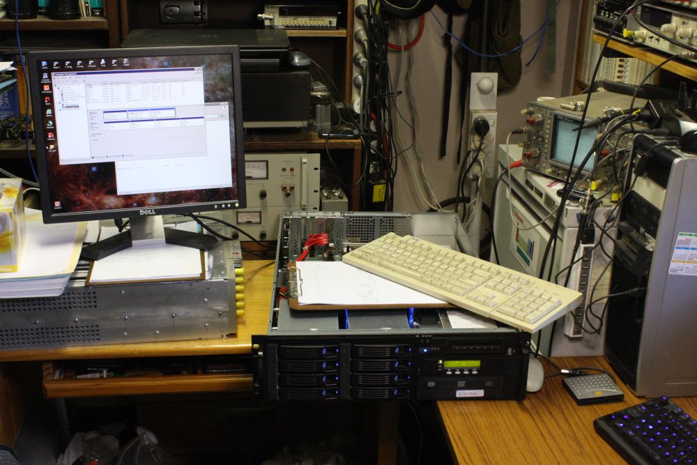
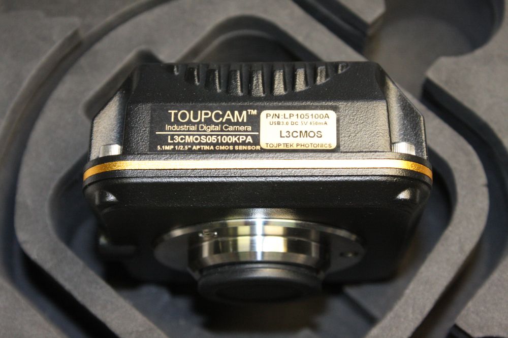
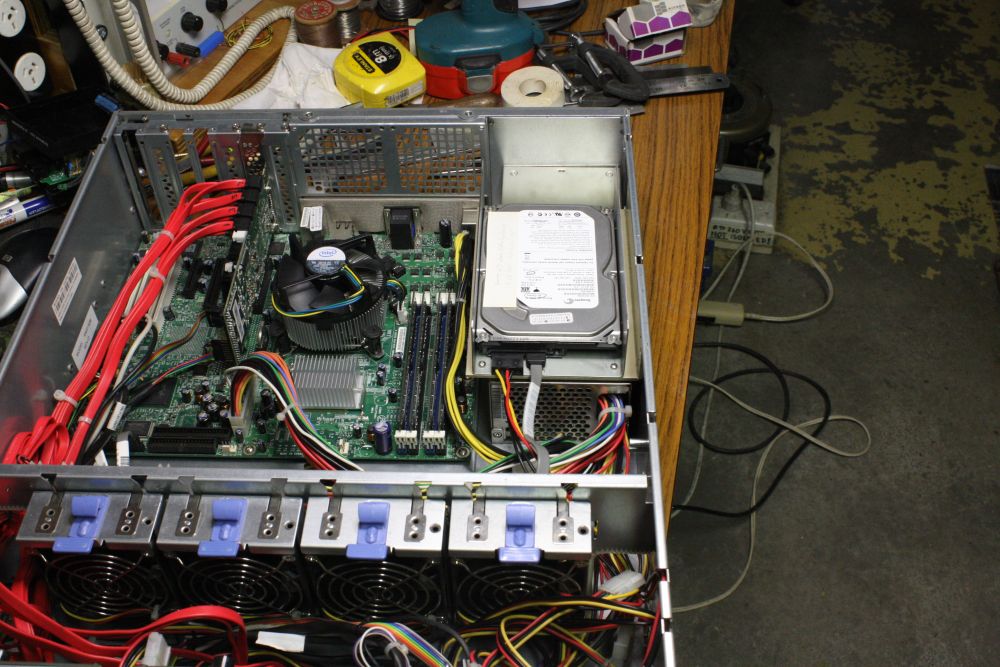
Now it works! All drives present, and after some grumbling the RAID BIOS presents four RAID arrays of a bit under 2TB each. I don't care what they are, as I'll be restructuring and formatting them. And a few other hacks to the machine too. This machine will be archival storage, and USB-3 server for the nice microscope video camera I bought earlier this year.
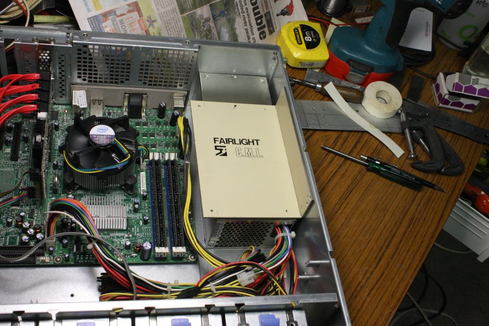
The first mod was to free the front small drive slot for a universal flash card reader. Which meant moving the existing boot hard disk somewhere else. The best place was above the power supply in the case rear. For which I'd need to make a support bracket.
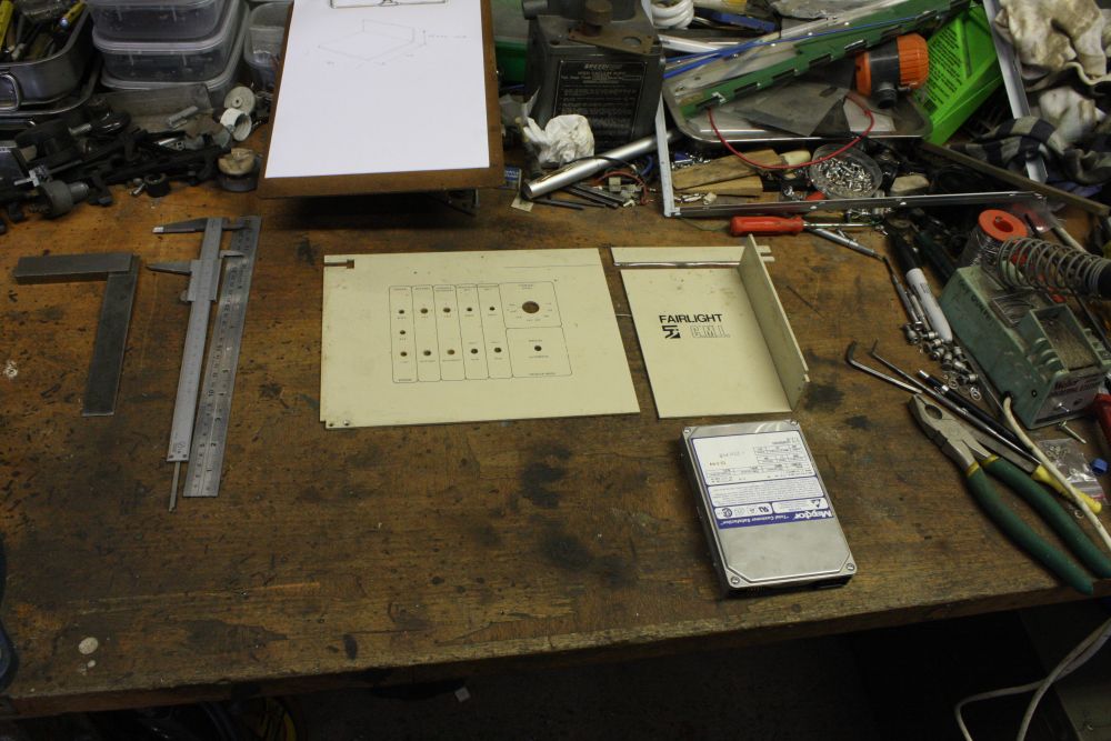
A bit of tech history here. Back in the 1980s there was a company called Fairlight Instruments, who pioneered the digital music synthesizer, The first one they sold was called the Series I. It used dual 6800 processors, in a proprietary 24 inch standalone frame. Some details here, and here.
I was working for them for several years in their Rushcutter Bay building, then later in the Alexandria building. In Rushcutters Bay one day, they were throwing out a lot of obsolete metalwork they had in stock from the Series I and some other products. The pile of boxes was sitting in the loading bay, and I noticed there were lots of useful aluminium sheet pieces. I asked if I could have them, and was given permission to take whatever I wanted. And so, among other bits I ended up with a foot-high stack of unused front panels from the Series I synth. They are nice thick aluminium, and only have a few small holes. Ever since, any time I need to make anything small out of 3mm thick aluminium sheet, that's what I use. Still have most of those panels.
 |
 |
 |
 |
 |
1. Hence making this hard disk bracket from a piece of history.
2, 3. Needed to drill some holes in the server case for the bracket. The bit of aluminium clamped on in Pic 2 is a bit of scrap used as drilling template, both here and on the drive bracket, so the holes are guaranteed to match.
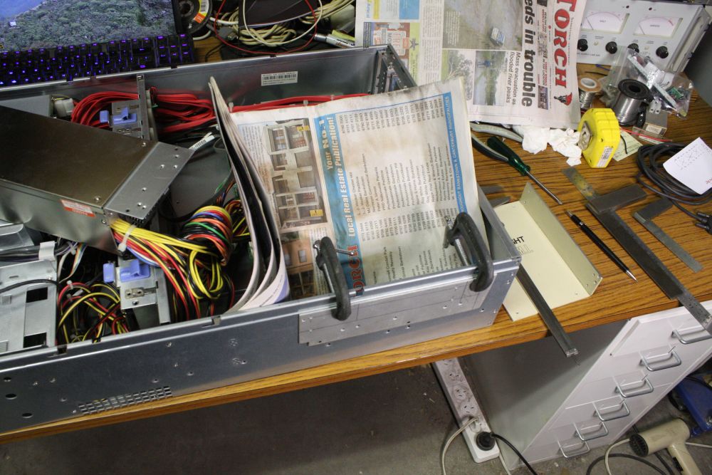
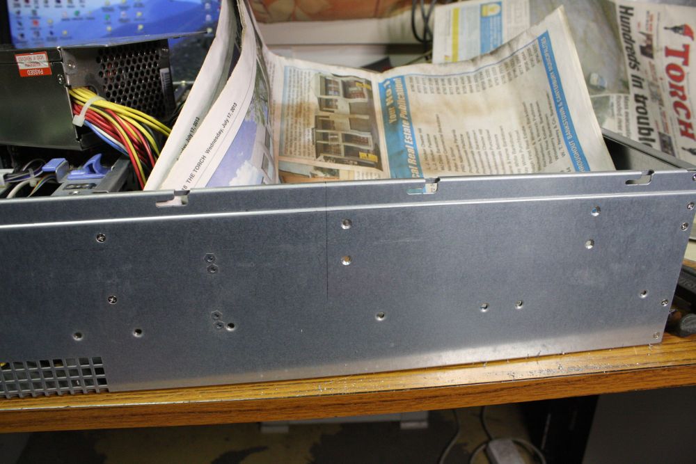
Drilling steel next to PC motherboards is not recommended, due to the risk of getting tiny but conductive bits of swarf on the motherboard, where they wreak havoc. So, newspaper and very careful vacuuming once done.
4. In place. There's a small gap between the bracket and the power supply, with a strip of foam tape in between to absorb vibrations.
5. Finally the HD mounting plate, made of sheet steel. Room for another drive too, if needed in future.
Now the machine is back in storage, waiting for a couple of other minor things. Not long now, I hope.
Ha ha, the usual several-deep chain of project dependencies. The microscope camera awaits this machine; at least two other projects stopped awaiting the microscope camera to be working... and so on.