For a project I've been working towards for years, one of the needs is an optical detector that works up into the GHz frequency range. When you're working on a shoestring budget, that's not an easy thing to find.
Back in Sept 2002 this item came up on ebay:
 The listing said:
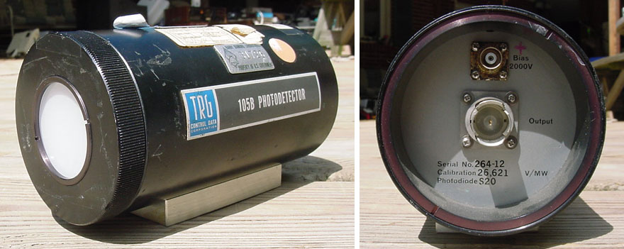
The TRG 105B Photodetector can directly measure the power of Q-switched laser outputs. To obtain a response from DC to 1.25Gc, the photodetecting photosensor element, the bias supply and the coaxial connector are part of one homogenous microwave structure. Unit has a rise time faster the .3 nanosecond, output of up to 70 volts into a 125-ohm load, a DC bandwidth to 1.25Gc, and an Output impedance of 125 ohms.
Very interesting to me! I hunted around on the net, but couldn't find any further information on these. It was originally listed at US$99, which I couldn't afford at the time. It didn't sell, was relisted at US$49. I was dithering over spending that (plus postage to Oz) on something looking quite dinged up and for which there seemed to be no data, when it sold.
Instant regret. I set up an ebay search, hoping another one would turn up.
Nada. Years passed without even a hint of one anywhere. Neither ebay, or even google. Presumably there were never very many of these made. Another factor in their rarity on the second hand market might be what they could have been used for. That brief seller's text mentioned Q-switched lasers, but for a laser detector there's no need to build the thing like a tank. For nuclear weapons testing though... such a use might explain their scarcity. Both due to secrecy, and potential contamination.
Anyway, that just piqued my interest. I really wanted one, both for its capability and to take it apart and see how it was constructed.
Finally in April 2016 another one appeared on ebay. But with a problem — that translucent white front aperture glass was missing. Another glass further in appeared to be intact, but it raised the question of what else was missing or broken. Listed for $50, the seller dropped to $40 when I pointed out the missing glass. I bought it, had it posted to my US reshipper.
Where it sat for a while, till I could afford the Au$60 postage to Oz.
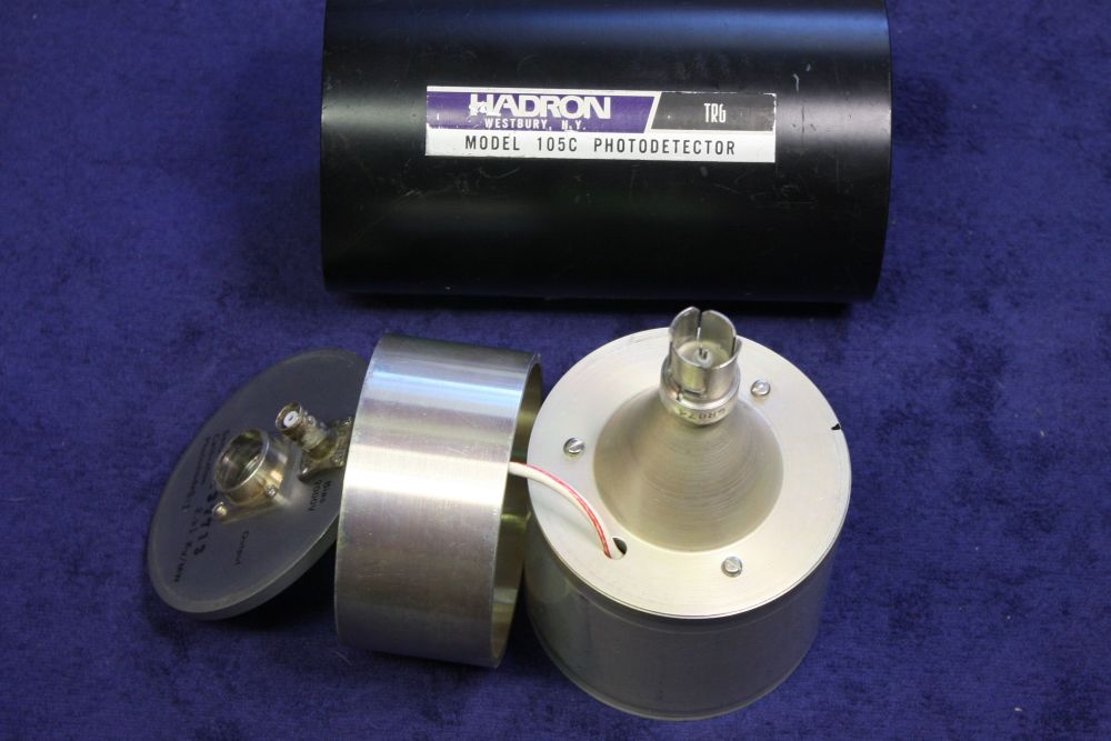
It arrived here today. So, here are some teardown photos. Only delayed 14 years from when I wanted to do this.
 |
 |
 |
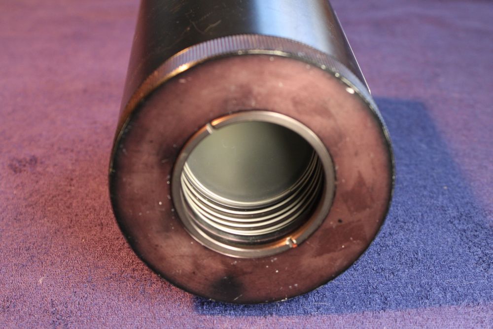
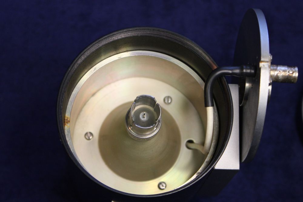
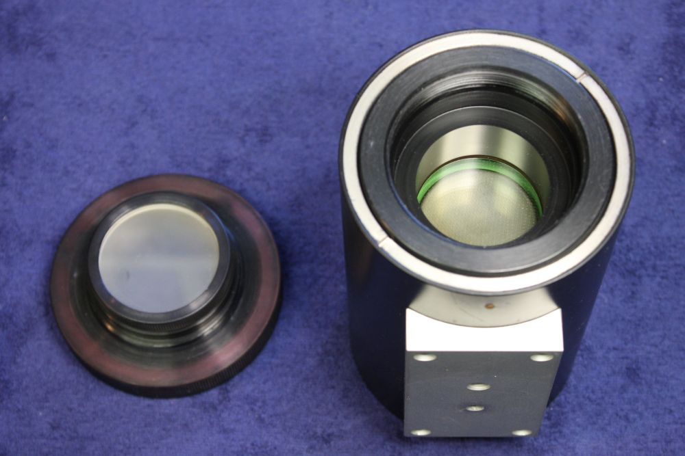
1. The inner 2nd diffuser glass visible. That spring is there to allow adding more such disks of glass in front of the sensor tube. Presumably filters, and there's room to stack a lot of them. Resulting in a very high light attenuation. For the obvious case where the unit would be looking at something extremely bright. Such as, oh I don't know, a nuke going off not far away. Alternatively I suppose that space could contain a block of scintillator material, for detecting things other than light from the same kind of source.
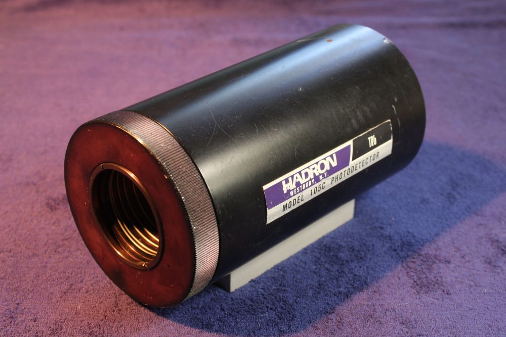
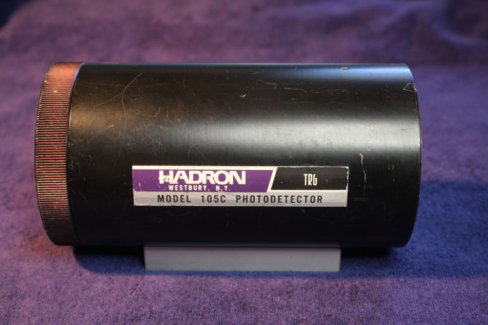
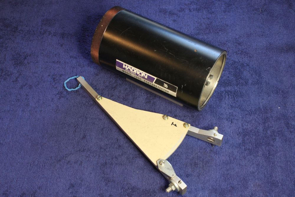
2. The one in 2002 was a 105B, by TRG/Control Data Corporation. This one is a 105C, by TRG/Hadron. The usual corporate mergers churn, plus a slightly later model. I don't care. Though, if they wanted to avoid hinting that these detectors were intended for hot nuclear physics, they shouldn't have named the company 'Hadron'. Which is a family of nuclear particles including protons and neutrons.
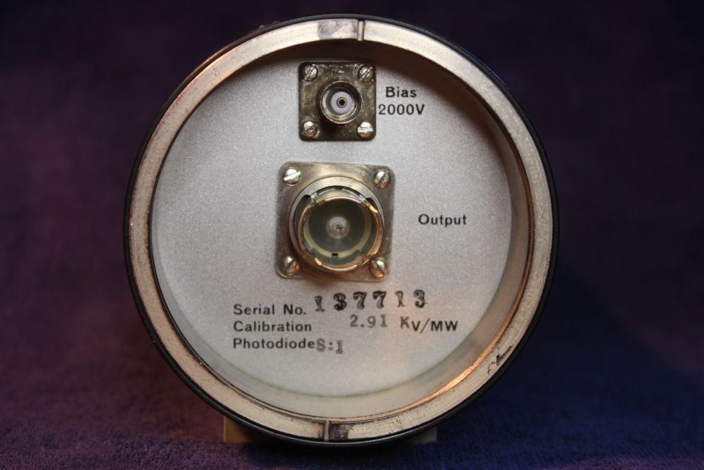
3. Slightly different details on the rear plate.
2002: "Serial No. 264-12, Calibration 26,621 V/MW, Photodiode S20".
2016: "Serial No. 137713, Calibration 2.91 KV/MW, Photodiode S1".
26.6 vs 2.9 KV/MW is a considerable decrease in sensitivity. Due to the different photodiode S20 vs S1 I presume. Is there any speed difference? (more on this later.)
The top connector is a HV variant of the standard BNC. The larger center one is a General Radio corp coaxial connector. It has the unique feature of mating with an identical connector, ie it is genderless. It's old, but no problem as I have an assortment of these already, including adapters to more common coaxial connectors.
What is a problem is the required cable impedance, according to that 2002 listing. Common coax cable types are RG58 (50 ohms) or RG59 (75 ohms.) RG63 (125 ohms) is much less common and I don't have any. Google says it's available, though finding a small roll cheap may be a problem.
 |
 |
 |
 |
 |
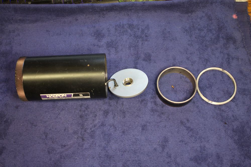
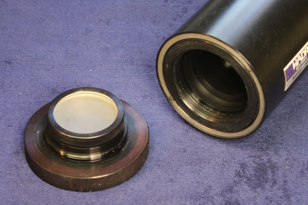
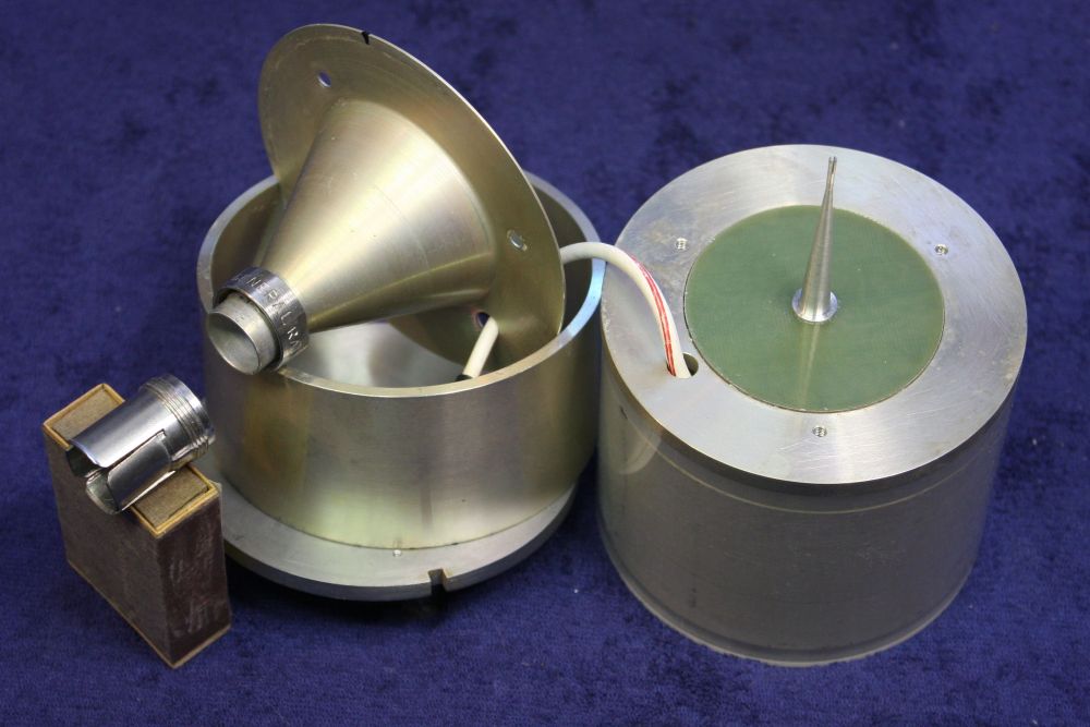
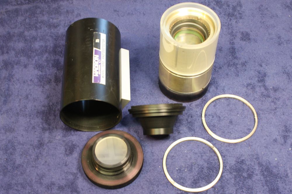
1. Disassembly requires one small Allen key, and a tool for turning those large threaded rings with a couple of small slots. I made such a tool long ago, for working on camera lenses. It did the job here easily.
2 - 3. I'm liking this a lot already. No electronics to fail in here! Just a conical structure that's probably related to impedance matching to the output coax.
Slight signs already that at some time in its life this instrument was left out in the rain. But very minor and easily cleaned.
4. At the other end that knurling turns out to have a purpose. The whole front filters assembly unscrews easily, giving access to the rear screw ring for loading filters etc to that spring-loaded space. There's no lock-screw on this, so it's meant to be opened easily and often.
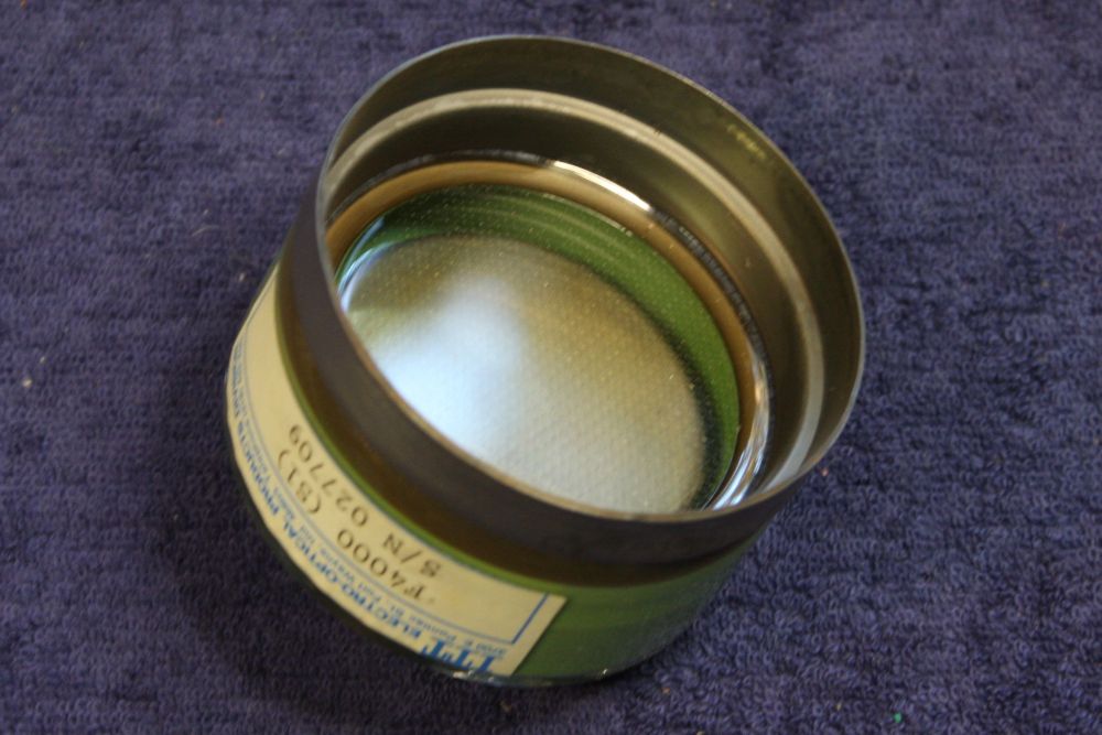
5. Moment of truth. Till this point I didn't know for sure that the internal photocell was intact. It is; you're looking into the face of a bare vacuum photocell. It's not a photomultiplier, just a simple photo-emissive surface adjacent to the HV mesh on the inside surface of the glass.
 |
 |
 |
 |
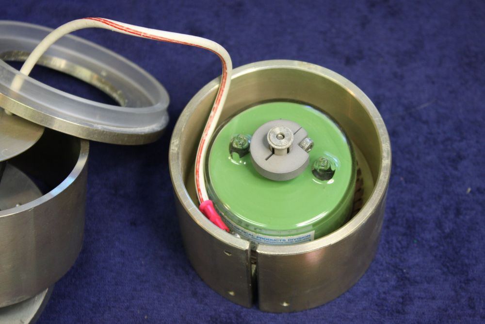 |
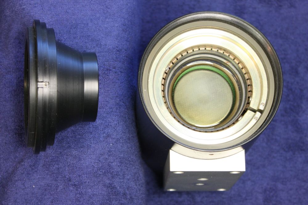
1. After removing another threaded ring and loosening off a grub screw, that black structure lifts out. It's plastic, and along with a plastic liner inside the main metal cylinder acts to insulate the entire metal structure seen here. These turn out to be directly connected to the 2000V input (which is +2000V btw.) This makes sense; the front mesh on the tube needs to be positive to attract the electrons knocked off the photocell cathode by photons.
2. Closeup. Some more slight moisture corrosion visible. But again it was all very superficial and easily removed. Now it's clear the tube is held in place with a circle of spring fingers. But how to get it out...?
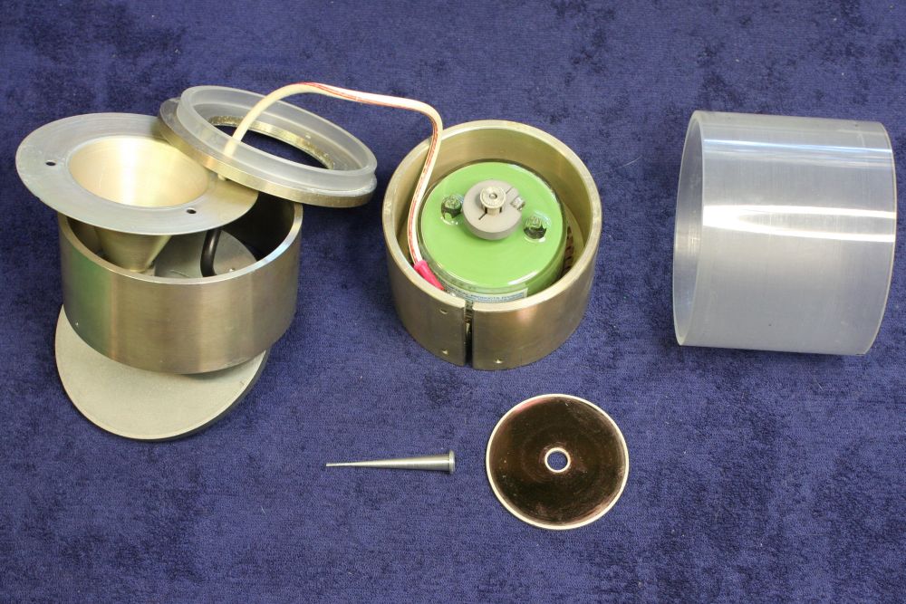
3. The whole structure slides out of the case. Looks like we need to approach the phototube from the rear. At this point I'm bearing in mind that the rear connection(s) to the tube will be delicate, in delicate glass seals. Care!
4. OK... That was a bit nerve wracking. The GRC connector's rear pin has to be pulled out of that tapered shaft, quite firmly. Since I couldn't see this till after it came apart, there was no way to be sure nothing was going to break. But there didn't seem to be any other way. Phew.
5. A series of terrifying steps. The end of that central tapered shaft obviously had to be connected pretty directly to the glass-seal parts of the phototube. But how to disconnect it? If I twist it, might the glass break?
Turns out it's screwed on to this structure, and the screw wasn't very tight. So after a slight twist I could feel it unscrewing without any 'snap' feeling of breaking glass.
 |
 |
 |
 |
 |
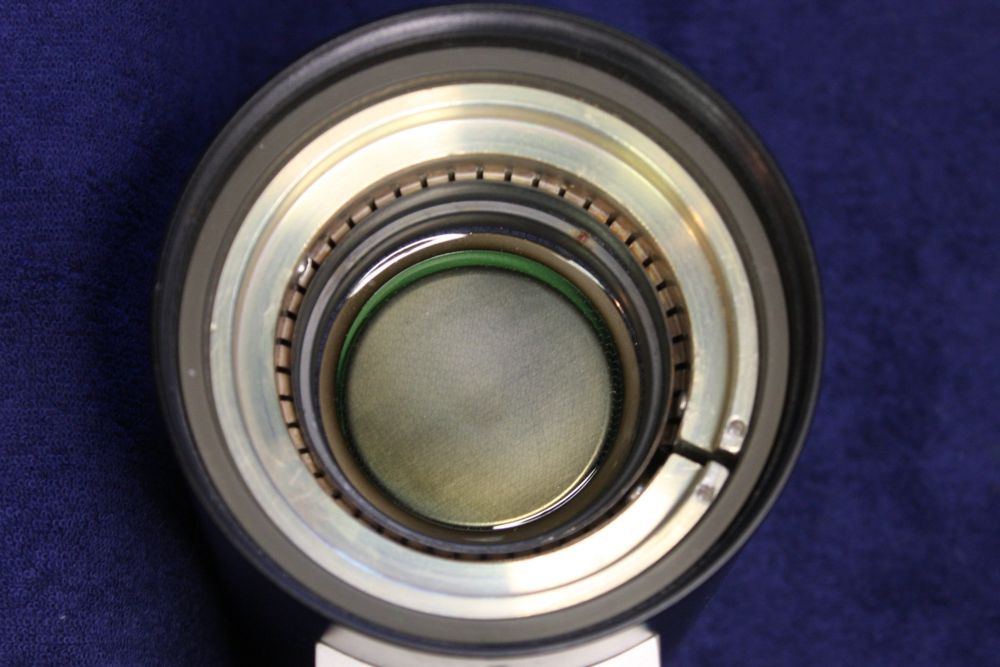
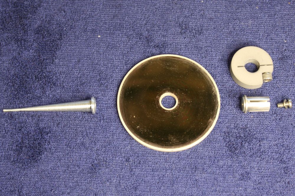
1. The other side of that green fiberglass disk in the previous pic set, is a circular thin-film resistor. It forms the load resistor from the photocell cathode to ground, and also the coaxial cable source impedance match. It's very fragile looking, so I avoided touching it or its edge metalizations. It isn't part of that fiberglass board, it's a thin flexible film laid against the fiberglass.
2. Two more scary steps without disaster. Firstly the tube just pushes out of the ring of spring fingers, but takes quite a bit of force to shift it. Then that split ring with the lock screw had to be removed, but the lock screw was oriented so a glass nipple of the tube obstructed the Allen key entry line. Solved with a ball-head Allen key, that could be inserted diagonally. The screw is very tight, and to avoid putting any stress on the glass I held the metal ring in pliers while loosening the screw.
3. Closeup of the thin film resistor. It's really the sole 'electronic' component in the detector, and boy is it an irreplacable oddity. If broken, forget about repair. The surface has some colour blemishes, but I'm not even going to try a small spot-cleaning. The total resistance value of this disk (center to edge) will be critical, and any scratches or surface wear will change it.
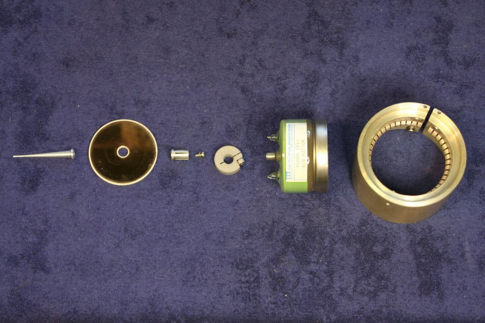
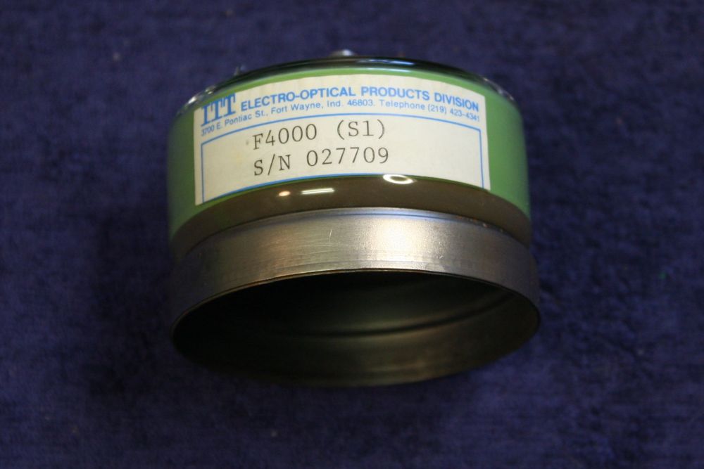
4 - 5. The tube. Well, well, TRG just armor-packaged someone else's product. The photo-detector tube is by ITT Electro-Optical Products Division, 3700 E. Pontiac St., Fort Wayne, Indiana. Presumably long since ceased to exist.
Excellent! This gives me a second chance to find some data on the device.
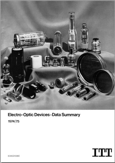
This time google comes up with something, though it's not much. From https://frank.pocnet.net/other/ITT/ comes an old ITT shortform catalog Electro-Optic Devices - Data Summary 1974/75.
Click on these for the relevant data:
 |
 |
Ah, so the "S1 vs S20" refers to differing spectral response of the phototube. But there's no speed difference.
 |
 |
 |
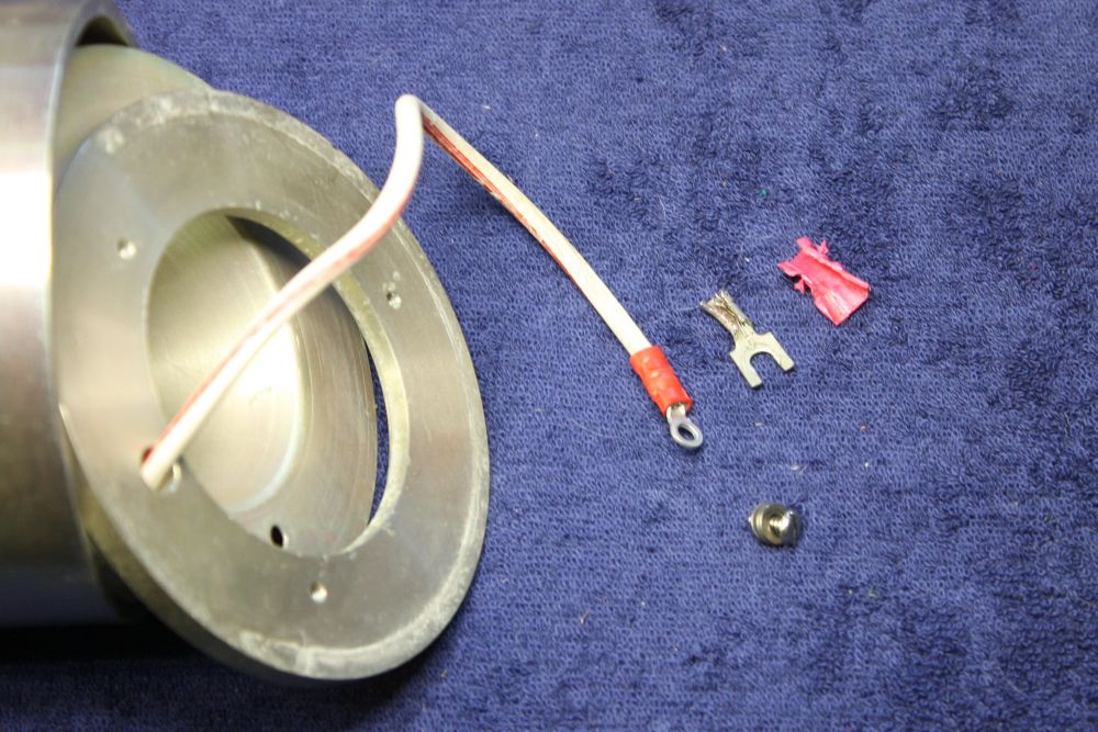
1. Annoyingly they'd put a lug on the HV cable that was too big to fit back through the holes in the metal rings. I wanted everything apart for cleaning. So I cut the lug off and replaced with a smaller one that fit the screw better anyway. And it doesn't have to be a spade lug.
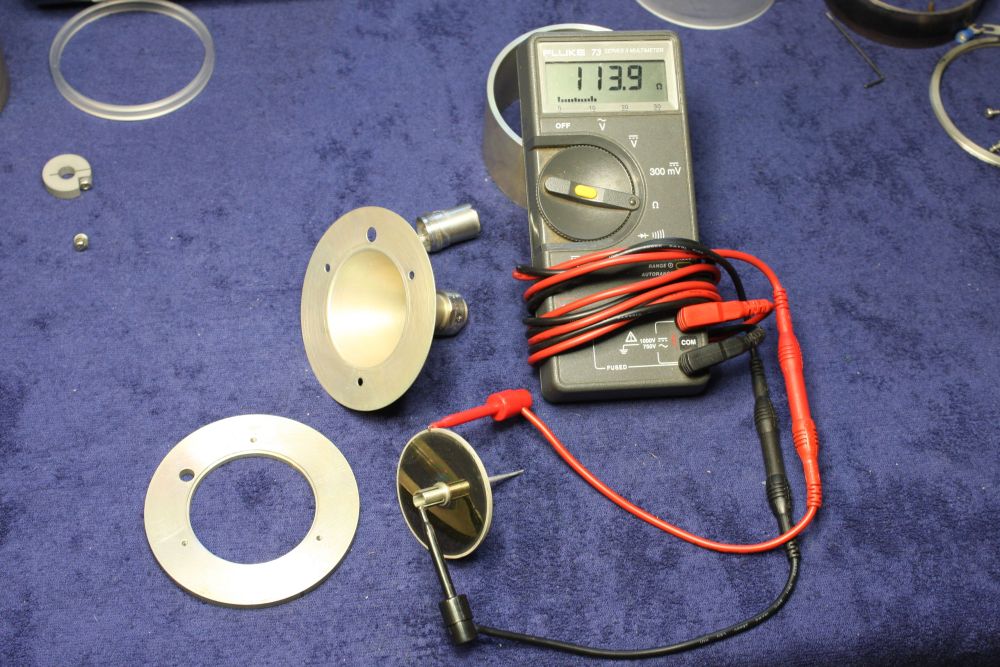
2. Beginning reassembly, with the load disk and connector structures. The resistance of the disk measures as 113.9, say 113.0 without lead resistance. Not far off the 125 interface impedance suggested. Presumably that guy had access to some data on the unit. Too bad he didn't bother to list a reference.
Something that had occurred to me, unfortunately after I'd removed that split lock-disk, is that it can be positioned variably on the sleeve. And since it is electrically equivalent to a distributed capacitance to the resistance disk, the position will certainly matter. In fact it's probably the one adjustment for response compensation. Sigh.
Fortunately there were still faint marks from where it had been originally, so I hopefully put it back close enough.
3. The remainder of reassembly went smoothly. All back together now.
The missing translucent glass front port disk should be 51.0mm diameter. Finding something equivalent to keep dust out of the entry shouldn't be too hard.
Next: trying it out.
Slight problem — I don't have anything that can generate very fast optical pulses. Will just have to try it at low frequency first. I have a suitable power supply, but will need to hunt up some 125ohm coax and terminators, etc.
To be continued...