We have a pretty big property (nearly 1200 sq m) and a nice big 2-story house built in 2000. With plenty of roof space. It would have been great to take advantage of the government incentives for solar power panel installations while that was going on, however we also have a lot of trees. Big ones, and I like them. The downside is all of the roof faces everywhere on the property are mostly tree shaded. The back yard too is mostly shaded, by the house and trees.
So solar electric isn't feasible here. Which is a shame, since I really like solar electric in principle and have long wanted to experiment with autonomous solar power systems. Not so interested in the 'politically approved' grid-tied systems with no power storage, since for me the ultimate goal is complete power independence.
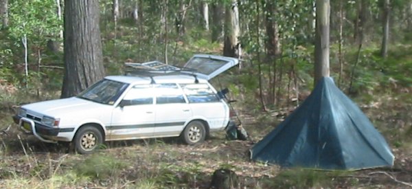 These are not the panels we're talking about
Back in 2012 I did buy a couple of small panels to use while car-camping. See A Bush Workbench. That system works well, but it's nothing like what my home and workshop needs.
It would be nice to have some large solar panels to experiment with, but they are still expensive and it's not sensible to buy them when they can't be put to much use here. If this property does end up having to be sold, then open space for a large solar array is definitely on the requirements list when relocating.
Then recently, once again Serendipity lent a hand. Early Thursday morning, 20160331, I walked the few houses up to the shops to get milk for my breakfast. On the way back, there was a van parked across the road almost directly opposite my house. A guy was loading what were obviously old solar panels into the van, with a couple still leaning against the front street fence still to go in the van. His ladder was still against the two storey house there, with shiny new panels on the roof.
On the principle 'grasp potential opportunities in the moment', and that he was obviously finishing up and about to leave, I quickly walked over and said hi, are you disposing of those panels, and could I possibly have them?
I then went into detail, about being a retired electronics engineer, and wanting to examine a bunch of old panels to see how they degraded, what kinds of faults, etc.
He had to phone his office to ask. While waiting for them to call back he explained they were a warranty replacement, since the house had been struck by lightning and they were probably dead. I said I didn't care, in fact that made them more interesting. (I was thinking it unlikely they were ALL dead, plus I would actually like to see the result of lightning-struck solar panels.) I asked how often that happened, and he mentioned only ever having had to do this about 6 times, in several years.
We talked about the idea of mini-inverters per panel with 240VAC outputs in parallel, vs panels in series and one bulk inverter. I mentioned the idea of a system with sense wires to each panel, logging stats of individual panels. He says there is such a thing, google "Tigo". The office called back with an OK, much to my surprise.
We stacked the panels against my front fence. He asked if I had a multimeter and I laughed and offered to show him my electronics workshop. But he was in a rush to another job and had to leave. He gave me the box of mounting hardware, and a couple of rails. He'd installed only 6 new panels, presumably higher efficiency equivalent to the 8 old ones.
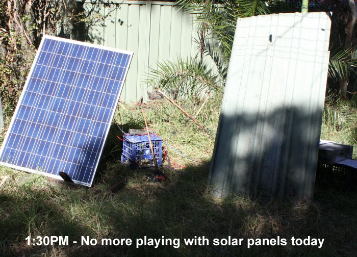
I moved the panels down the side of the house, then had breakfast. Afterwards moved them to the back yard, laid out in the sun.
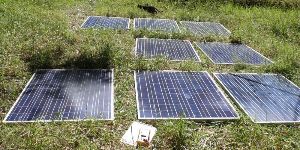
Btw, if you like your lawn, don't do this. I discovered the panels get hot enough within minutes to completely cook the grass in neat rectangles. Luckily I don't care about the grass.
These are probably another result of that wild electrical storm on 20160129, that took out some of my equipment too.
Now it's a cloudless sunny day, perfect for measuring their output. By 11:30am I'd tested each one and recorded values. Open circuit V, and short circuit Amps only. Wrote values on the panel frames in marker pen, then copied to paper, numbered them on paper in rough order of functionality, then wrote the unit numbers on the panels too.
The sorted data:
   Voc    Isc(A)
1  30.0   8.2
2  29.7   7.2
3  29.9   6.2
4  20.2   8.0
5  20.6   7.3
6  20.3   7.2
7  19.9   7.4
8  10.3   6.5
Number 8 is pretty dead, the others all seem not bad, and quite worth using.
Figures taken with the panels manually tilted up to approximately point at the sun. But a few minor shadings - long grass, clothes hoist, etc.
They all have some dirt and small lichen growths on the glass. Cleaning them may improve the figures a bit.
Panel model info (from label)
Ningbo Qixin Solar Electrical Appliance Co Ltd
Type:  SL190CE-27P
Peak Power (Pmax)           190W
Production tolerance:       +-5%
Max power current (Imp)     7.15A
Max power voltage (Vmp)     26.56V
Short circuit current (Isc)  7.65A
Open circuit voltage  (Voc) 32.56V
Weight                      17.0Kg
Dimensions    1485 x 990 x 40mm
Wind resistance   2400 Pa
After that I stored them away under cover. I'd been in a rush, had other things to do, and no time then to set up for measuring output power curves. I did notice that their output voltages were all near 10V, 20V or 30V, but put that curiosity away with the panels. For later.
20160412
I had mentioned these panels on eevblog, and a few days later on 20160412 a member commented:Ah ha! Of course, the diodes. I knew panels included diodes in parallel with groups of cells to protect cells from reverse current flow when shaded. But it had slipped my mind and I hadn't yet opened any of the rear junction boxes so wasn't reminded by actually seeing the diodes.
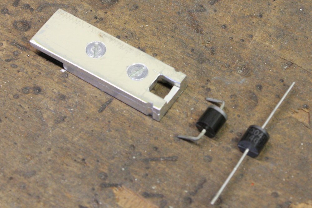
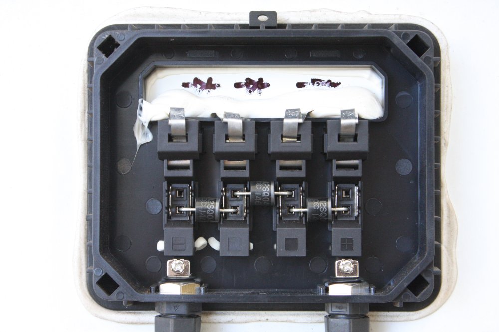
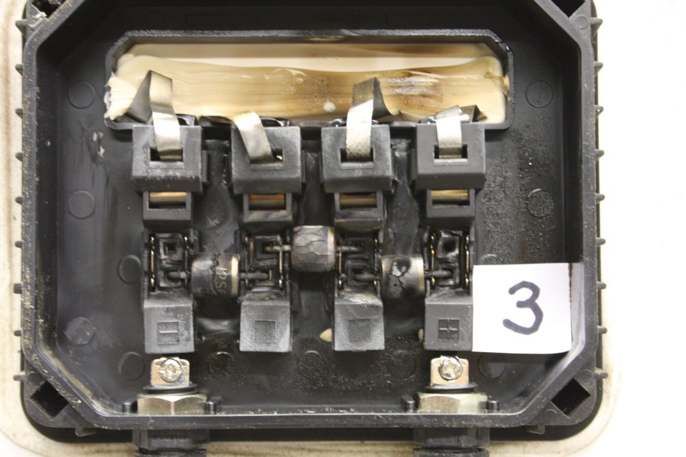
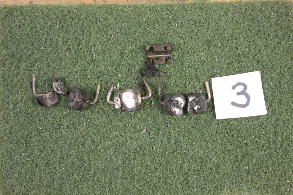
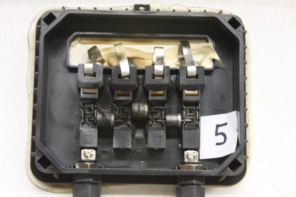
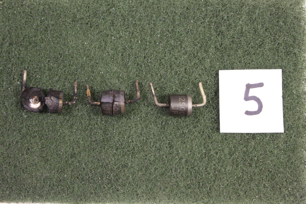
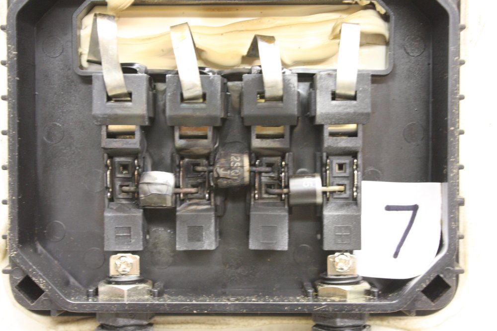
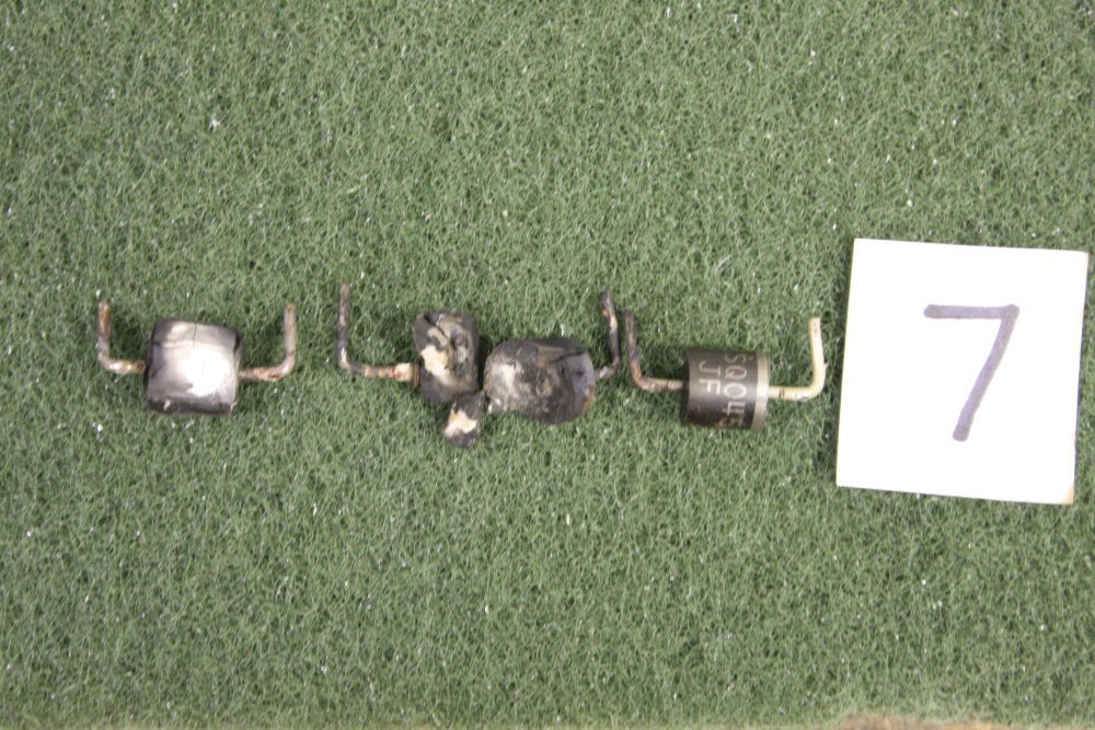
Now this was exciting. I dropped other tasks and pulled one of the panels from the pile. Picked #8, the worst one. Opening the box revealed three diodes — one for each string of 18 cells. And it was immediately visually obvious there was a diode problem, since one of them was discoloured by heat. Sensibly, the diodes are merely clipped in rather than soldered, so they can be pulled out easily. (Pics below.)
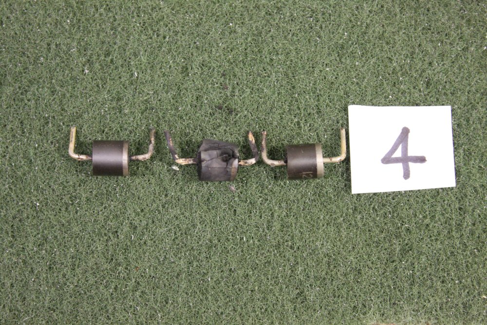
On measuring them the result was kind of the inverse of what I'd guessed from just looking at them. But it did explain the low (10.3V) output voltage. The two diodes that looked unburned were dead shorts. While the overheated one was around 300 ohms in both directions. Which makes sense; dead short means no power dissipation, while that 300 ohms 'resistor' was being solar-heated.
It was evening then. Under room fluro lighting without the diodes, the three cell strings (each 18 cells in series) produce 5.87V, 5.99V, 6.4V. Pretty close. The differences are likely mostly due to uneven lighting across the panel.
This was good news! Three diodes, hence that 'rule of three' clustering of the panel output voltages. I'll need to replace all the faulty diodes then re-measure the panels. Possibly, I may have 8 fully functional panels.
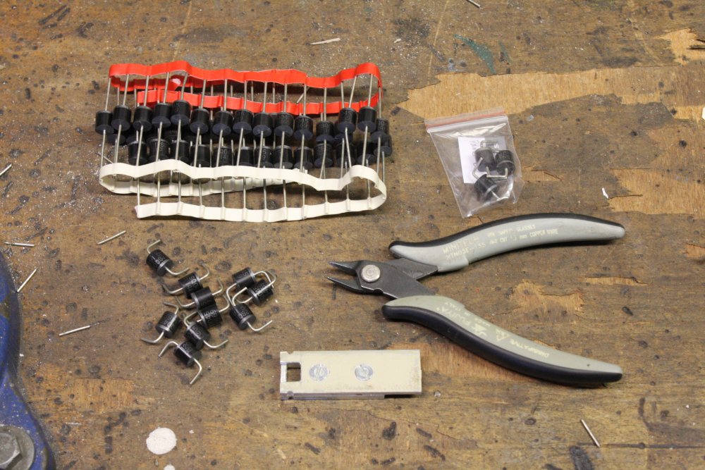
The diodes are 12SQ045 ( Schottky, 12A 45V, Vf=0.55V@10A ) Commonly available. I ordered 50 for US$15 via aliexpress.
20160420
Finally had some free time, and it's a sunny day. Took panel #8 outside (with no diodes installed) and measured its output.Voc: 31.9V Isc: 8.03A Excellent!
20160502 Mon
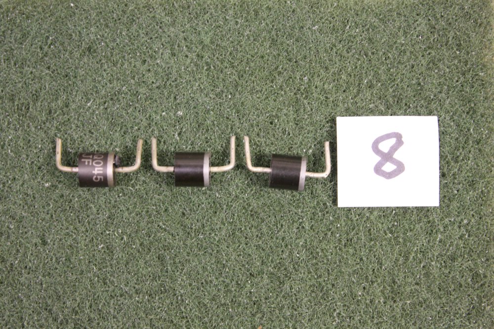
The 12SQ045 diodes arrived. Qty 51. Measured Vf @ 10A = 0.41V Better than spec.20160503 Tue
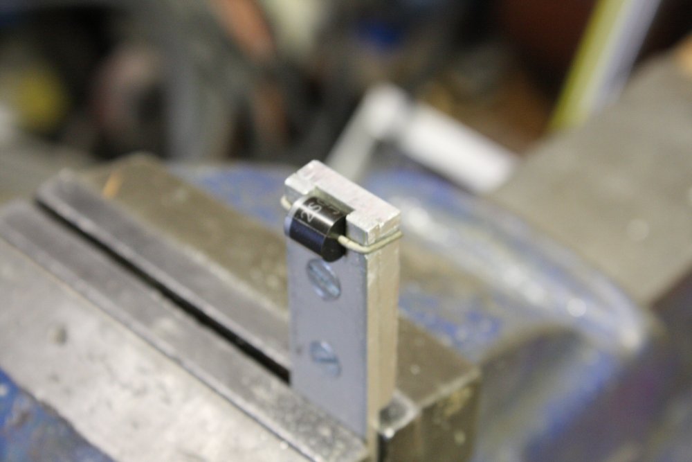
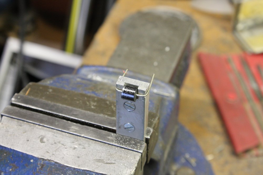
Made a lead former/cut guide for the diodes.
 |
 |
 |
 |
 |
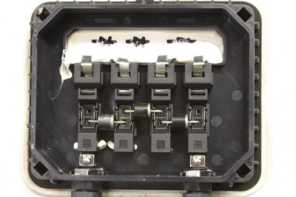
Lead-formed about 10 diodes. Put three in panel #8, clipped on the cover.
Missed the 3 hour slot when sunlight reaches an area of the back lawn today, so will fix and re-measure the other panels another day.
20160504
Cleaned all 8 panels, checked operation of my electronic load, started setting up for loaded panel measurements but ran out of sunlight as tree shadows crossed lawn. Another day.
 |
 |
 |
 |
So how do you characterize a large solar panel's output, under varying load conditions?
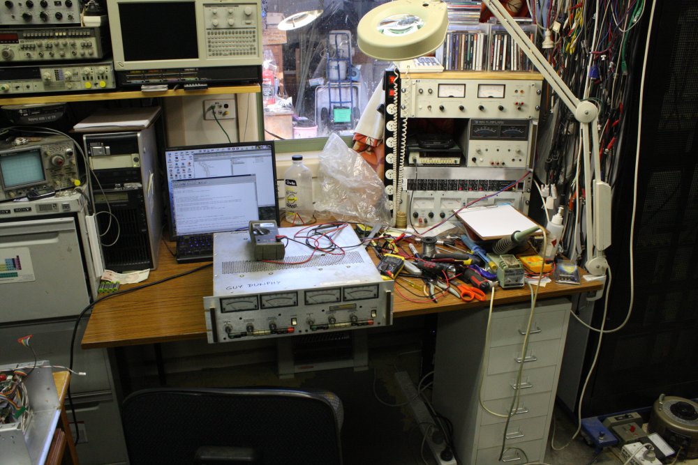
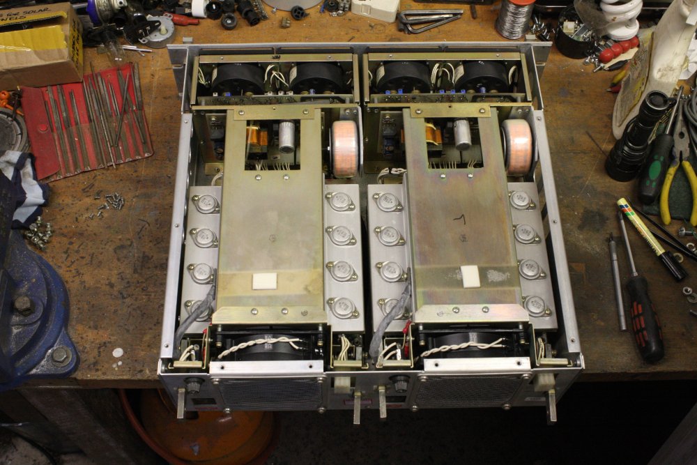
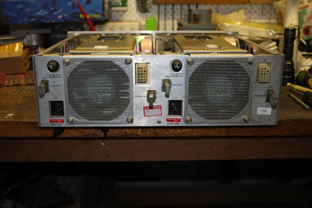
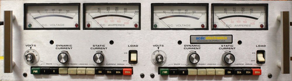
You need an electronic load of some kind. Like this EL750BR (which is a dual EL750B, in rackmount form.) It can act as a variable current sink, or a resistor. At max 60V and up to 200A current loading, which is pretty cool. Hence those big copper busbars sticking out the back, that are the terminals. For this use the 0 to 10A range will be suitable.
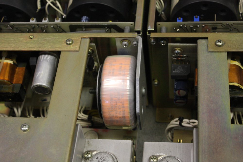
It's a nice unit, but when I got it back around 2000 I found that the US manufacturer was one of those who don't bother to make their gear switchable for mains voltages other than the US 110VAC. I had to improvise by having two small torroidal transformers custom made, and making mounting brackets to fit them in.
While cleaning the panels I noticed a few of them have lines on some cells that are either cracks, or something like Lichtenberg figures - lightning breakdown current paths. Hard to tell from outside the glass.
While testing the panels I should note these patterns (draw diagrams.) So can see if there's any correlation with performance figures.
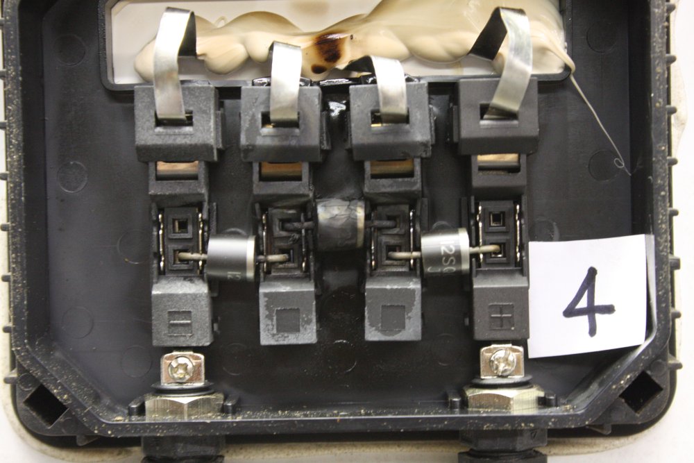
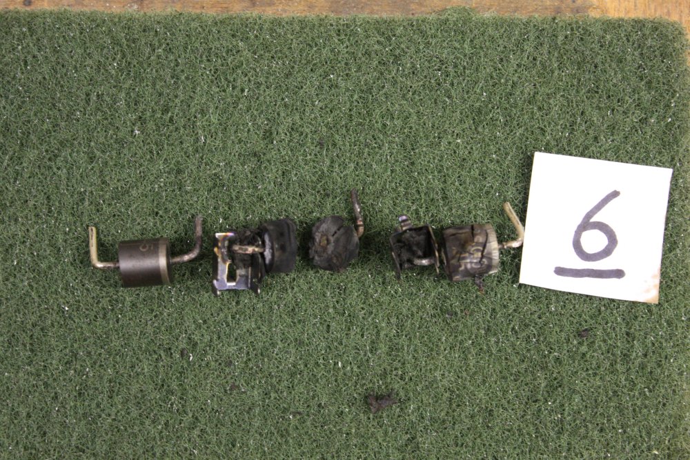
In the evening I replaced all the many dead diodes. Urrgh. Panel #8 was actually one of the better ones, as you'll see.
Also took some pics of the visible cell defects. They are definitely lightning-induced EMP tracking. More on this later.
 |
 |
 |
 |
 |
 |
 |
 |
 |
 |
 |
 |
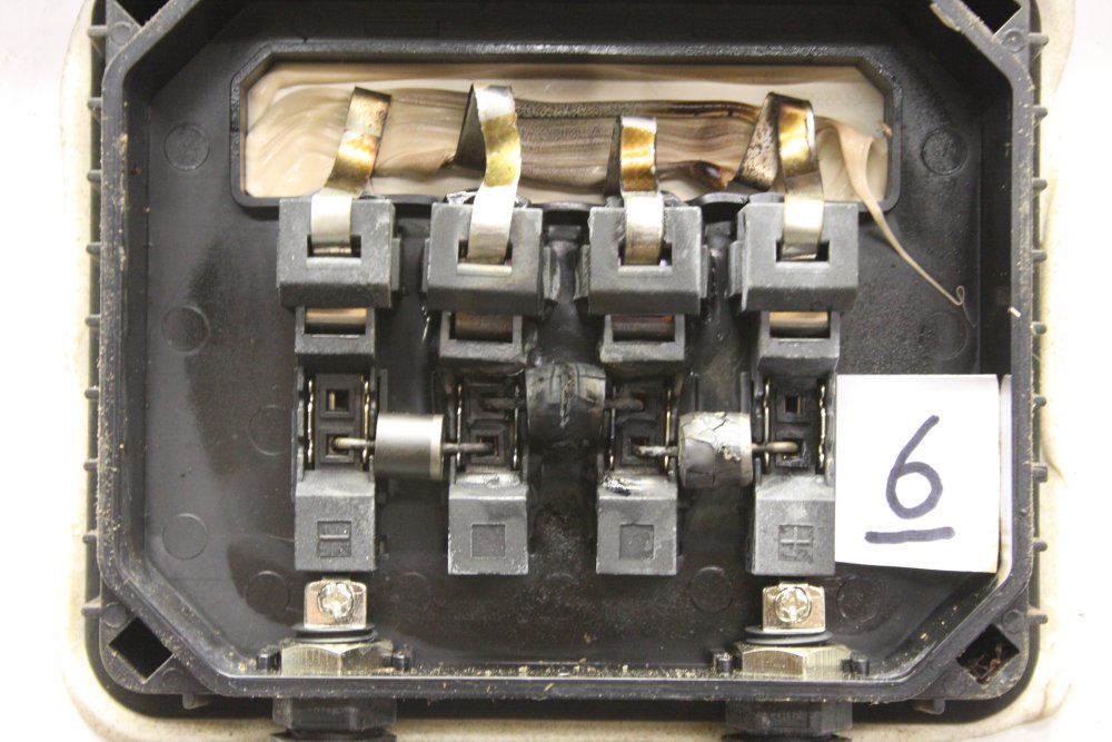
Apart from being horrible, this was interesting. All this visible burning and melting was not done by lightning. It's clearly the result of considerable heat dissipation over a lengthy duration. More on this too, later.
Despite the large amount of melted plastic, the contact fingers for the diodes are apparently made of stainless steel, and still got a good grip on the new diode legs. Checking continuity from the diodes to the cell straps, they all made good contact. So although the insides of most of the boxes look nasty, they still work.
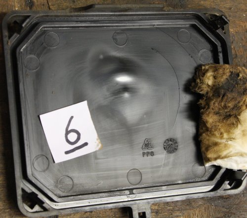 One major problem is that daily heating/cooling cycles from the wrecked diodes have caused cracks in some of the box clip-on covers. Like this one from #6, which has two semi-circular cracks.
But that too can be fixed. If it isn't possible to obtain spare covers, then a bit of hot plastic welding will do the job. Won't look pretty, but who cares?
The dirty tissue is from cleaning off the 'condensed essence of burning diode case fumes.' It's a nasty oily substance, probably toxic, it stinks, and from past experience it's also corrosive to metal. It cleans off reasonably well with methylated spirits.
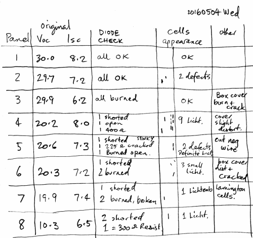 The notes taken while changing the diodes.
In the 'Cells Appearance' column, the little drawings represent roughly where the visible cell burn-lines are on the panel.
Observations:
2. The panel with the most visibly damaged cells is not the electrical worst, it's in the middle. (Remember that was with the damaged diodes in circuit, so may not mean much.)
3. The electrically worst panel only has one visible cell damage.
Aside: that should have been an <ol> list, but there's a html bug in both Firefox and Opera with ordered and unordered lists to the right of a float-left image. The point markers fall to the left of the page, rather than stay with the text. Even if the whole text is wrapped in a <div>. Google finds no sensible workaround. Ha ha, html/css still sucks so much, even with the simplest things.
20160506 Frid
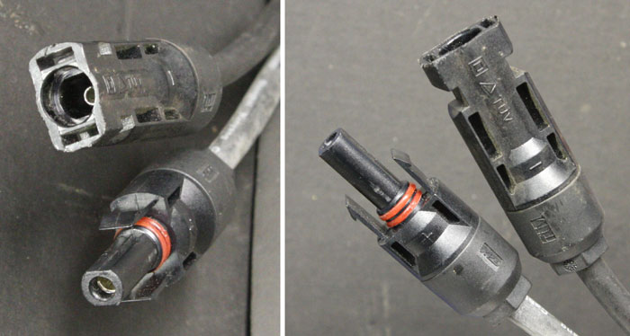 Another obstacle to load-testing panels, is these connectors on the panels. They are waterproof high-current mating pairs, designed to link strings of the panels together. Quite nice, but if you don't have any extra, how to make a stable contact?
Previously I was just holding multimeter probes in them, but that won't do for current vs voltage profiling.
Turns out a banana jack fits well in the positive (with the O-rings), while a small alligator clip was good enough for the other.
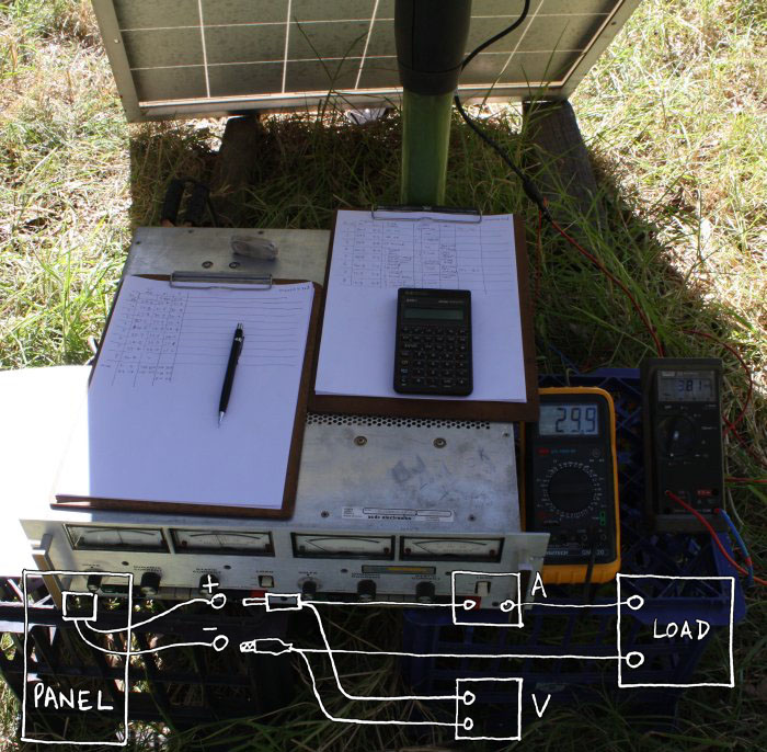 By strange coincidence, the clothes hoist is right in the middle of the only part of the yard that ever gets any sun. So it became part of the setup.
Aim: to record the panel voltage at 1 Amp load increments from zero to 8A. Using digital meters rather than the analog meters on the EL750BR.
One modification the electronic load needs is a 10-turn pot on the current setting, as with the present 3-turn pot it's still a fiddly pain trying to set current to x.00 Amps. So the current settings are all +/- 0.05 A.
I'd expected the current to voltage relationship to be a curve with voltage dropping off gently. But it turns out there's a very sharp knee, where above a certain current voltage collapses rapidly. Too unstably to get a good sampling of the curve, so I settled on taking two or three values for each panel, at whatever current the control knob achieved just past the knee.
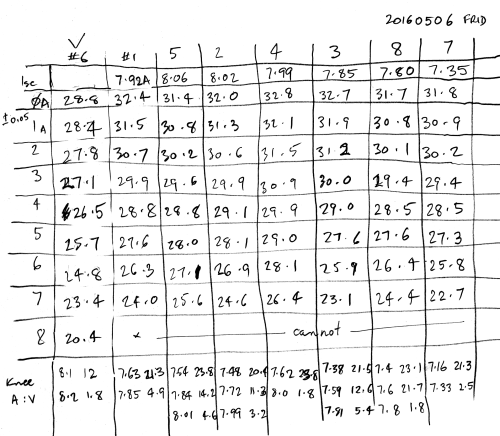
I did panels in the order they came off the stack in the workshop. Hence the random order of columns.
Only after I'd done the first one I decided to also re-measure Isc, so the first one (panel #6) is missing that.
The graph below is the end result. Panel data is shown in the resistor colour code for 1 through 8. The top set of curves are the current vs volts measurements from the table, using the left hand V scale.
The lower three curves are output power vs load current, for panels 7, 4 and 6. (Earliest knee, average, and highest knee.)
However notice that's also in reverse time of day order, so possibly some or all of the spread may be due to differing solar radiance.
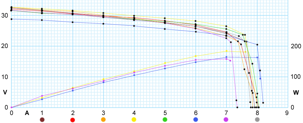
Overall, the panels are pretty good. The worst one was still delivering a peak output around 159 Watts, and that's with the sun mid way down in the sky (afternoon, May 6th in Sydney.) The panels are rated "Peak Power (Pmax) 190W" but you can bet that's only under ideal conditions.
Panel #4 was delivering 184.8 Watts, which under the far from ideal conditions is amazing.
Why panel #6 (blue line) was a couple of volts lower than the others, I'm not sure. Possibly because with that first one I hadn't yet noticed the clothes hoist was rotated so a bunch of clothes pegs were shading the panel. Or maybe it really has some cells shorted. Sigh... I'll have to set it and another panel up again and re-measure. #6 has very little visible arc tracking damage.
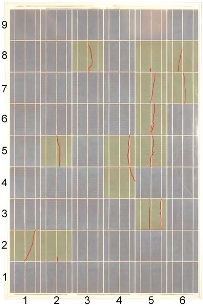
Which brings us back to the visible lightning damage on the faces of some cells, because strangely, panel number 4 was the absolute worst in that respect. It had 13 separate damage points, several of them quite large. While the next worst panel only had 3.
Here's Panel #4, with damage emphasized. Click the highlighted cells to see closeups.
 |
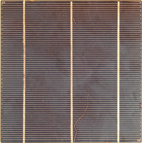 |
Well that's not very exciting, is it? Teeny little snail trails?
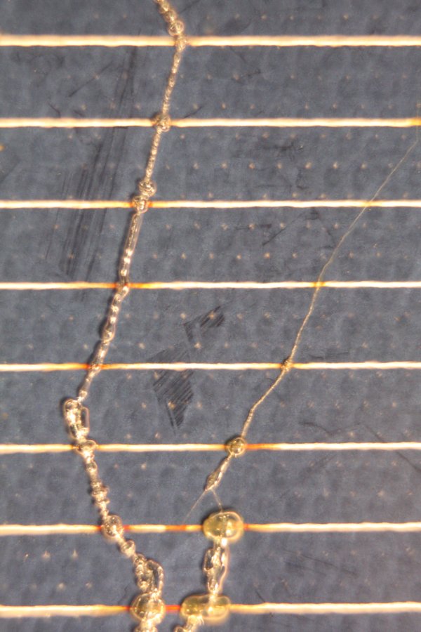
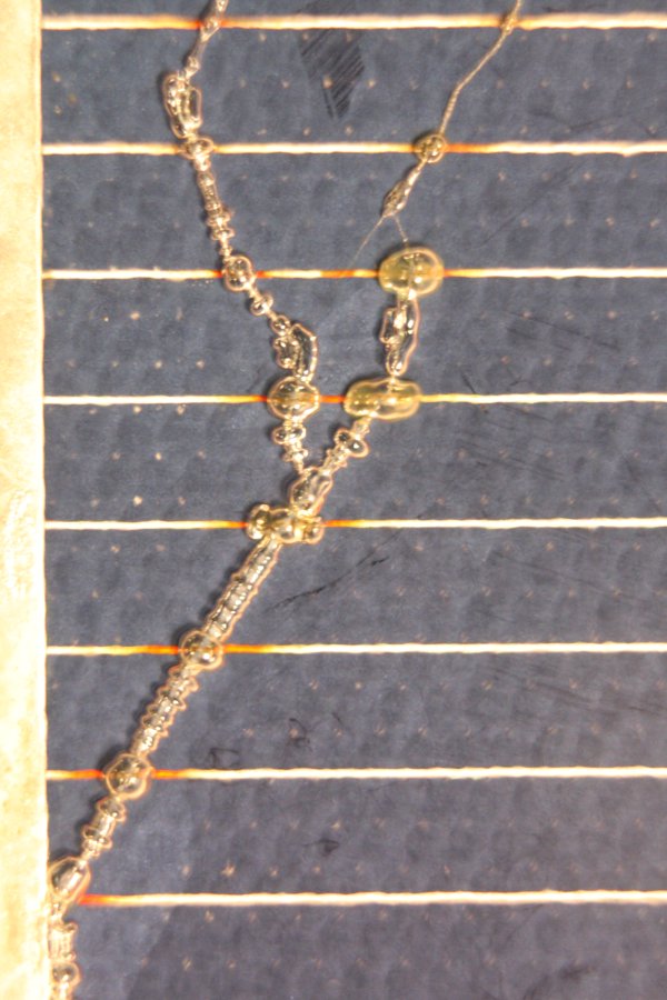
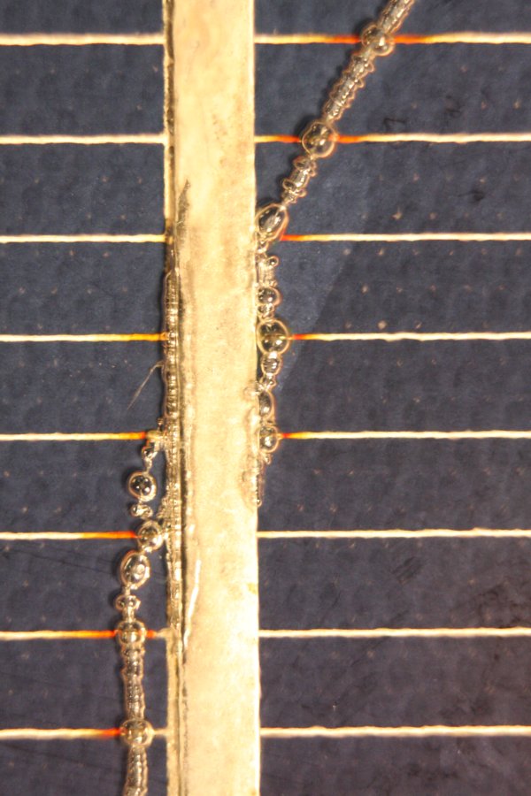
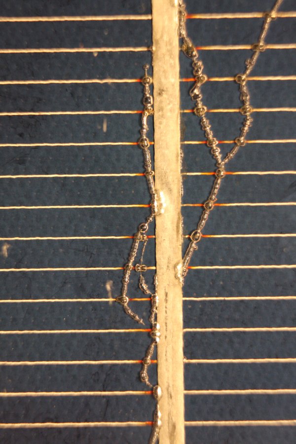
So here are some magnified views, taken with a macro lens extension.
 |  |
 |  |
 |  |
 |  |
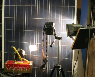 Big solar panels are a bit awkward for macro photography, being so big. This one I hung vertically from a rafter, and placed a heavy object behind so it couldn't swing. With the camera on a tripod, it was doable.
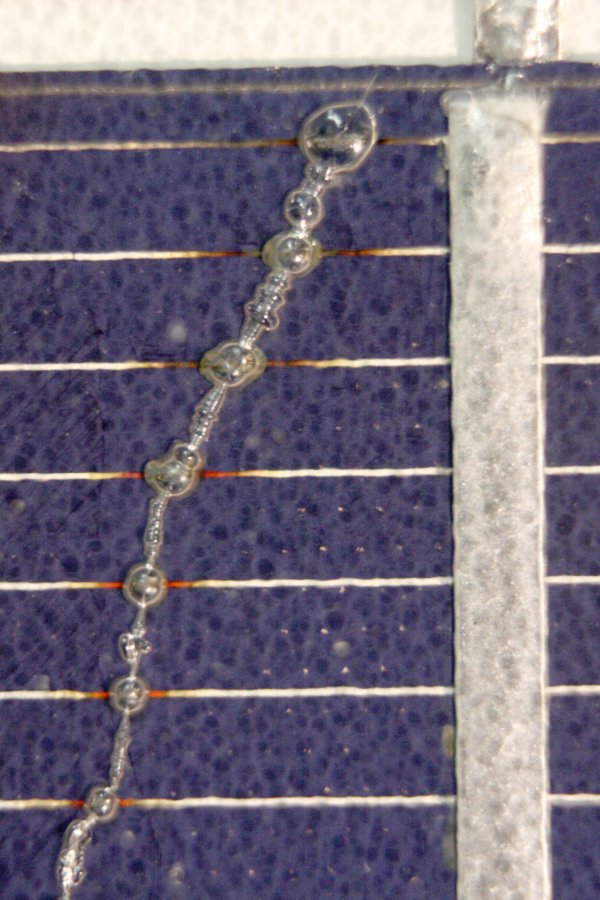
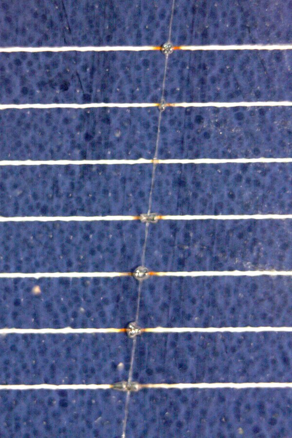
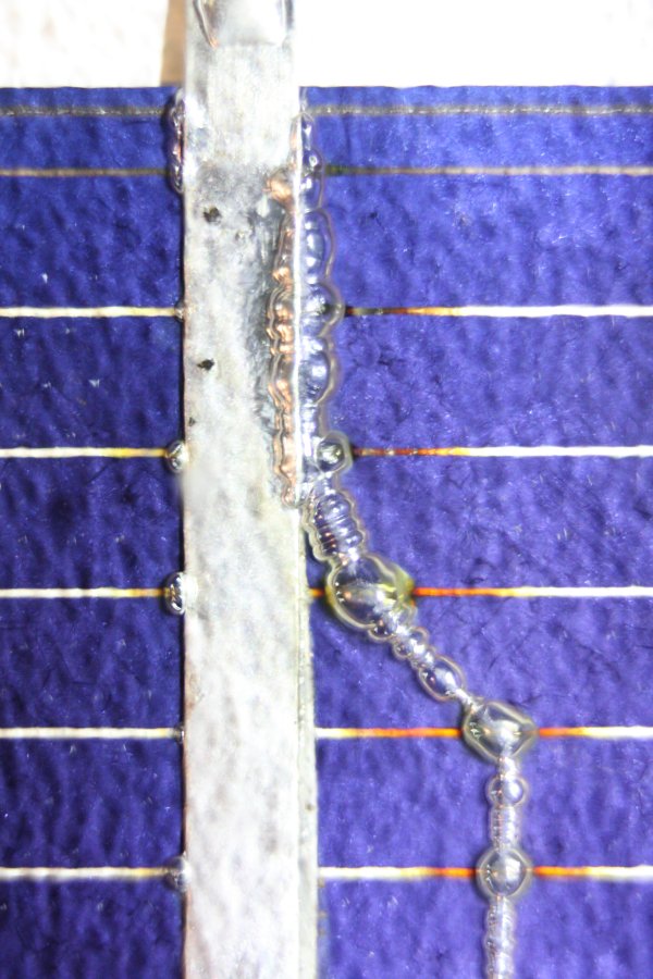
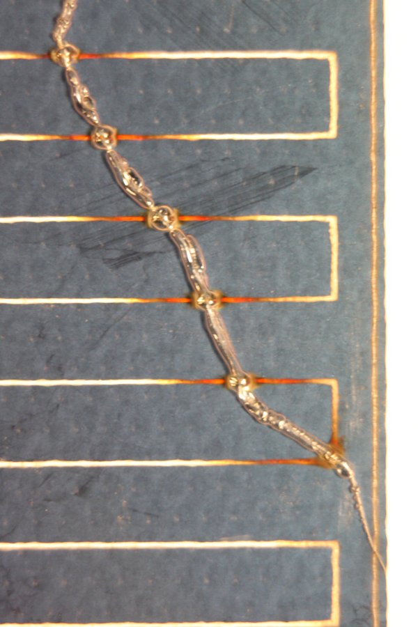
But what exactly are we seeing in the pics? I'd originally assumed the cells were in a cavity between the clear front glass and white backing glass sheet. But from the pics it appears that isn't so. More like the space between sheets and cells is filled with a very clear substance, perhaps a silicone compound. In any case, when subjected to fast arc current breakdown it seems to form small bubbles and cavities. With surprisingly clear inner surfaces.
At least that's how I interpret these images. I guess breaking open a panel and dissecting one of these trails would be the only way to be sure. Also the only way to even begin to examine what's happened to the silicon cell surface along those tracks.
But the key point is, we're looking at panel #4, which works better than the other panels with fewer or none of these tracks.
That's really curious, don't you think? Just a coincidence? Or not...?
Diagnosing Individual Cells
While I was measuring the panel outputs under load, it was becoming obvious there was no consistent difference between panels with visible cell arc tracking, and ones that seemed pristine. That was unexpected! I still had some time of full sunlight left, so tried an experiment to look for any difference in behaviour of individual cells, damaged vs undamaged.
But wait, do you think they are all sealed in glass and wired in series, so there's no way to measure the output of individual cells?
Well there is!
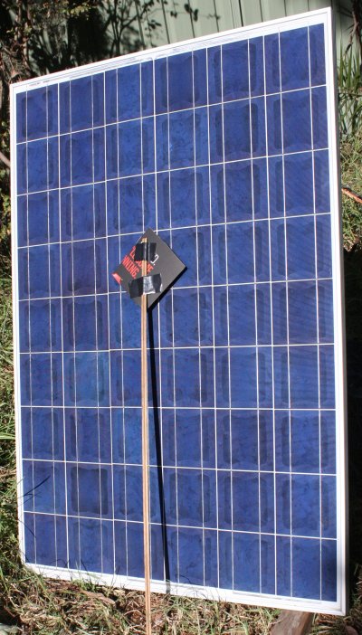 I cut out a cardboard square (from a pizza box) slightly larger than a single cell, and taped it to the end of a long stick. Now I could completely shade any individual cell in a panel. (Holding the square aligned with the cell, not crooked like in the pic.)
The idea is that shading a working cell will produce a repeatable voltage drop from the panel (operating under load) and that all working cells should individually produce the same output drop when shaded. Any cell that acts differently must have a problem. For instance if it was completely shorted, shading it should produce no change.
I started with panel #7, reasoning that it had one very definite cell damaged, so that would be the suspect one to check.
After setting the panel load to 5.02A, panel voltage with no cells covered is 24.4V. (Which is lower than earlier, showing that the sinking sun angle is having measurable effect.)
Then covered each cell in sequence. With one cell covered, panel voltage is 16.0.
Amazingly, this is true for all cells, including the badly arced one. So the damaged one is operating as well as the others!
Repeating with panel #4. Load current: 5.02A. Unshaded panel V: 27.1V, with one cell covered: around 17.3V. I say 'around' because at this point I was having to move the panel sideways to avoid fast-advancing tree shadow, so there was some variation. But I'd re-cal against unshaded, and in general this 'shadow scan' showed the panel had no cells that behaved differently to others.
Weird. This panel has 13 different arc-markings on cells all over the array, and yet has the highest output!
It's hard to believe, but there it is. Almost as if the lightning induced arc-overs somehow improved it?
Incidentally the panel pictured above is #7, and if you look closely you can see why I noted "lamington cells". It's the only panel that has this odd border colouration of the cells, where they look like a cross section through a Lamington.
At that stage I hadn't done the graph and didn't realise that panel #6 has a significantly lower output voltage compared to the others. Perhaps it has a few cells shorted? I'll have to try the cell-shading test with it another time.
Conclusions
There are some design lessons to be learned from what happened to these panels.
The diodes are supposed to be there to protect cell groups from damage due to reverse current. No doubt they do that.
They also have quite low reverse breakdown voltages, so perhaps can act to protect the cells from externally applied high voltages, since the diodes break down and probably fail short-circuit. But this is only effective against relatively low bandwidth external stresses.
The induced effects from nearby lightning strikes have voltage rise times far too fast for the diodes to do anything useful. They will die, but even if they were actually a piece of wire beforehand, they still couldn't prevent the kinds of high impulse field breakdowns seen on these cells.
Then, after the diodes fail, the real problems begin. All the actual serious, unrepairable permanent damage to these panels (the burned junction box fittings) was directly caused by the presence of the diodes. Once they fail they apparently are as likely to become resistive rather than dead shorts. Dead shorts would be good, since they don't convert the current passing through them from still functioning cells, into heat.
But when they become resistive, they typically dissipate much of the total power developed by their cell string, into heat within the plastic junction box. If this is allowed to continue for any length of time, the junction box will be severely damaged.
Conceivably, in some circumstances it could initiate a fire, despite the flame retardant plastics used. The boxes are seen to be cracking, could develop openings, and the panels are up on very hot roofs, with potential accumulations of dry leaves. Almost invariably there will be more leaf accumulations in gutters where any falling on-fire pieces are likely to end up.
The only way to alleviate self-heating damage and fire risk once panels develop diode failures, is to collapse the voltage produced by the cell strings. By either removing the panels from sunlight, or short circuiting their output connections. Either one of these must be done as soon as possible after diodes fail.
It would be advisable for solar systems to monitor cell strings for sudden step changes in cell string output power. Once detected, an urgent alarm should be given to human operators, and ideally the system should automatically short circuit either just the failed panel, or the entire string of panels if there's no connection to individual panels. Current will flow, but the voltages present across cell strings will be too low to cause diode overheating. This will prevent further serious panel damage and fire risk. Because the plastic diode mounts will be undamaged, the failed diodes can be replaced easily, resulting in like-new panels.
Possibly the best way to perform the panel short-circuiting, would be to include a relay inside the junction box. Or one per cell string, same as the diodes. This could be electrically driven from the master control system, or perhaps some thermally tripped device that stays tripped until the panel is serviced. Obviously, it's desirable to avoid more connections to the junction boxes (cost, weatherproofing complexity, etc), so the thermal short-circuit scheme seems most promising. There already exist very cheap bi-metalic overload cutouts, that open contacts when overheated and have to be manually reset. For solar panels this just needs to work in reverse - contacts that close when overheated. If the device could be made in a similar axial form to the diodes, very little design change would be required. The diode clip-in strips could be made with extra row of contact points, and a thermal protector plugged in adjacent to and above each diode. Allowing them to be easily replaced along with the diodes, if damaged or not resettable.
Alternatively, since existing panels like this have two rows of insert contacts, allowing the three diodes to be staggered, that leaves a spare contact in each of the end strips. So a single thermal protector could be retrofitted to existing panels if it was made with a suitable length. Just plug it in. It would short the whole panel when tripped, which achieves the desired result of protecting the panel, and would also make sensing of the fault by the main inverter very easy.
Ah. No, wait. A single short across the panel end-terminals isn't enough to prevent heat damage in the junction box. Because there's a case where the two end diodes have gone open-circuit, but the middle diode went resistive. Then the middle diode will still burn itself and the mountings. So it's necessary to short circuit all cell chains individually, ie one shorting contactor per diode. Pity.
There's a discussion thread over at eevblog.
This article is still in draft form. Several sections to add yet:
* Mention the connecting foil strips are supposedly silver.
  Ramificactions when (not if) silver price resets to historical norm (& url to links lists)


* Discussion of ways to EMP-proof solar arrays.
  - No protection scheme distant from the cells (and that includes in the junction box on the back) can protect
    against the kinds of breakdown traces seen in these panels. The rise time of the E-field
    arriving at the panel/cell faces is simply too fast for electrical involvement of anything
    further away than a few millimeters. Witness how the arc traces almost ignored very close-by
    main silver conductor traces.

  - Something like a metal mesh Fadaday cage around the panels might work. Not sure what mesh
    opening size would be effective.
     - How much shading would result?
     - How to clean the panels, when enclosed in a mesh cage?
     - Mesh is extremely efficient at trapping leaves, twigs and other debris. (But could protect against hail?)
     - Effects of electrical cables passed through the cage?
     - Perhaps the conductors should be coaxial? Coax with fat conductors for low loss with high current is not common.

    It's relevant that the tracking on these panels does not seem to have functionally impaired the panels.
    Maybe the best strategy is to ignore the tracking, but detect diode failures and replace them immediately?
    Slower EMP effects with cable runs need to be considered too.


Why these issues are important to some
If you are using solar panels solely for the power cost advantages, and don't envisage any kind of social crisis,
then you can just use them as they are and either rely on warranty or building insurance to replace any that fail
for whatever reason. If you're wrong, well bad luck.

If you are using solar because you are a Prepper and attempting to plan for various potential social collapse scenarios, then you
do need to think about these things.
Because it's entirely possible that at some stage during a collapse there might be EMP events. Or, your installation
might have a direct or nearby lightning strike after the collapse. Or even just a heavy hailstorm.
In any case, finding replacement panels after a general collapse is going to be very hard or impossible. So you need
to consider all means to preserve the panels you have. Laying in a stock of replacement diodes would be just a start.
But making sure failed diodes are not going to irrepairably burn and melt the panel junction boxes should also be high on your list.

Hence, thermal panel-shorting devices would be a good after-market product, for preppers.


EMP recording device
The bubble-tails left on these panels suggests another idea. The combination of a surface that promotes breakdown conduction paths when hit by an EMP field, with a clear material that cavitates and retains the cavities permanently, suggests something like the cloud chambers used to record nuclear particle trails.
Seems like it would be easy to make large panels optimized for this effect, for use in EMP experiments.

Mention similarity to: (and include pics):
 - CD-in-a-microwave effect.  (But it's not the same thing! Explain the effect.)
 - Lichtenburg figures in plastic. (Also not the same)  https://en.wikipedia.org/wiki/Lichtenberg_figure
 - Fulgarites (close similarity, but STILL not the same thing)
 - Skin tracks on people near lightning strikes.  See https://en.wikipedia.org/wiki/Lichtenberg_figure pics.
    Some maybe due to 'side streamers', but many probably *exactly* the same effect as on these panels.
    Migration and channeling of local free charge carriers, under influence of the E-field wavefront emanating
    from the main lighting-strike extremely high current and rise-time path.
 - Show the 'exploded tree trunk strip' I found on a bushwalk, describe scene. Explosive flash-boil of tree sap in layer just below bark, in a narrow strip.