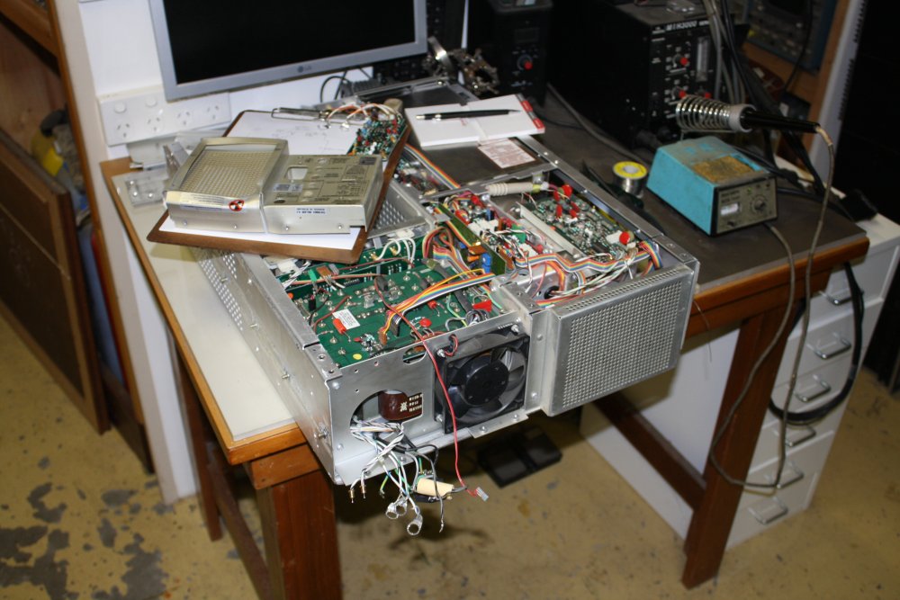
This begins as a repair, of an old Tektronix R7633 rackmount oscilloscope. Then it becomes a historical detective story, looking into the dying of a famous product line from a great company in the last days of its greatness.
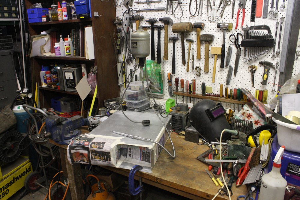
In the years after we built our new house in 2000, the 'garage' I'd built myself for the family to live in tween houses was finally all mine, as a workshop. It was still cluttered with building materials, but there was space to start acquiring the kinds of equipment I'd longed for all my working life. Not to mention things I figured I'd need for a little project — what the workshop was principally for. My list included a decent oscilloscope in each of several equipment racks. For these I chose to obtain various Tektronix rackmount versions of their 7000 series.
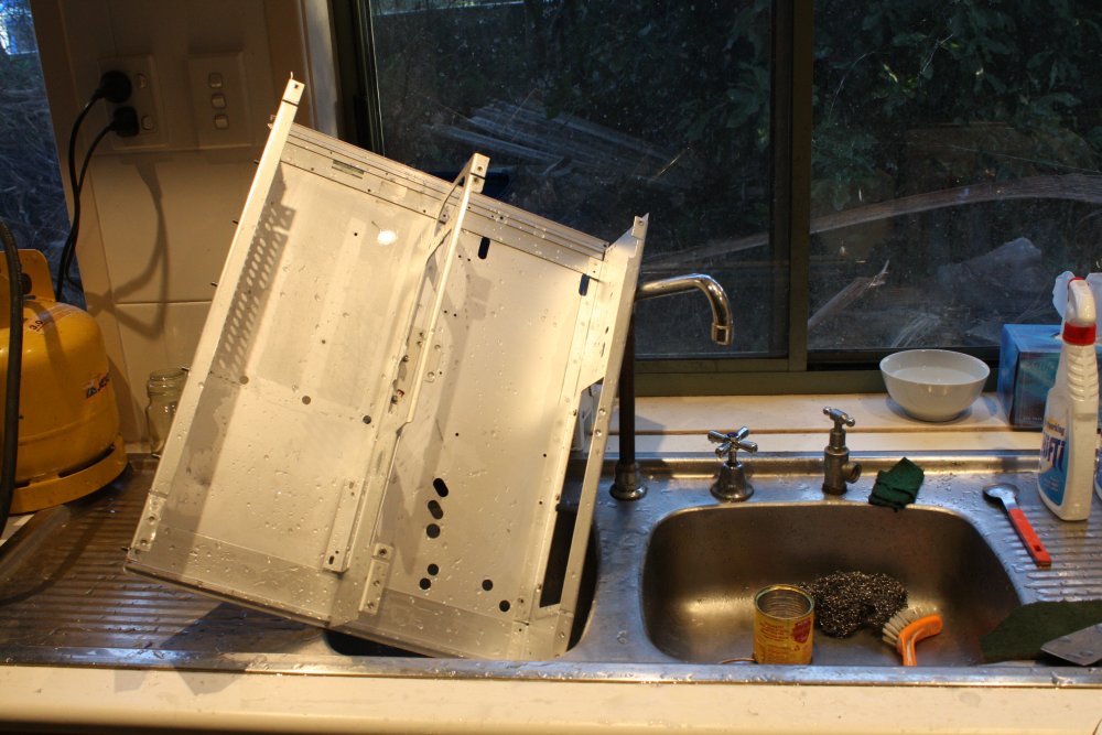
 One of these was a Tek R7633 scope, which is a storage tube variety. I wasn't terribly enthusiastic about digital scopes at that point, and besides, money constraints meant I could only buy old things.
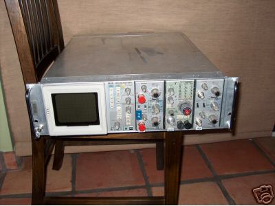
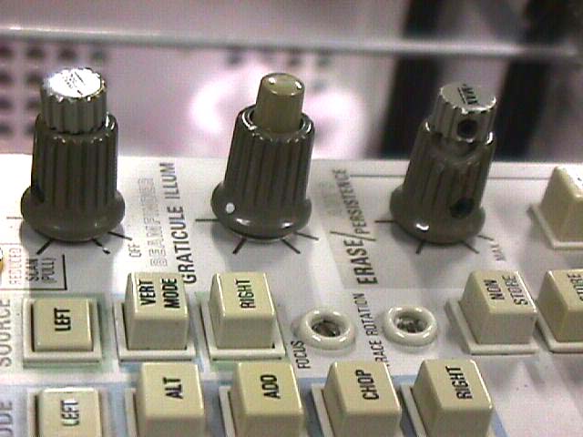
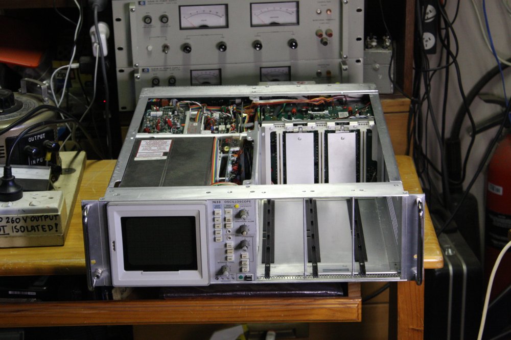
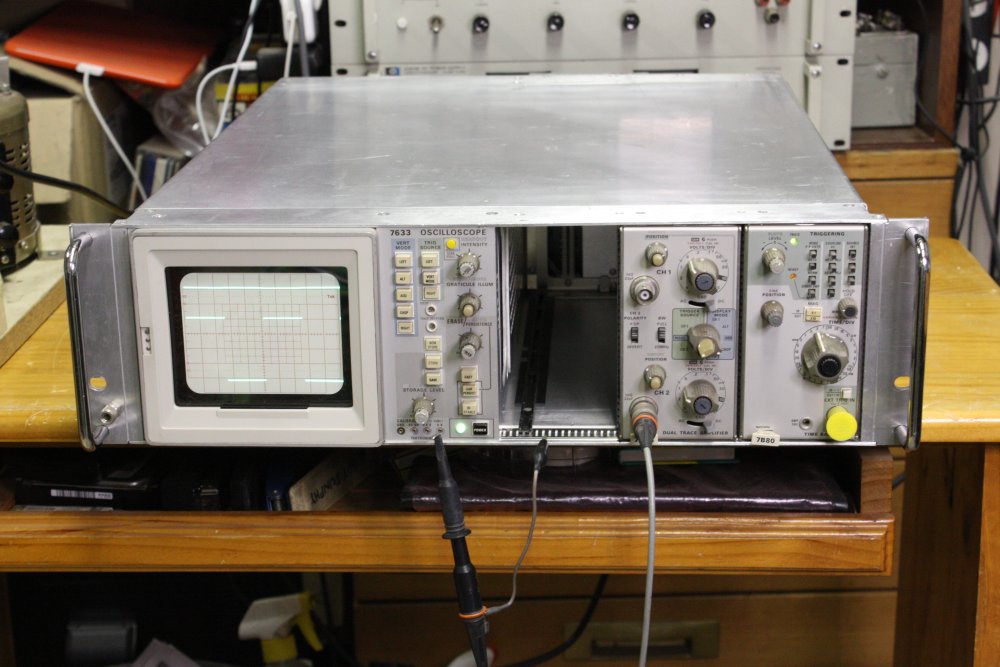
At left is the US seller's ebay listing photo, from 16th June 2004.
Those days I was relatively new to ebay (only had 200 rating then) and even more green regarding shipping from the USA. Probably should have read the seller's feedback comments, since "94% positive on only 33 total score" isn't very good. Also the photo shows the timebase module plugged into the wrong slot. It won't work like that, which shows the seller doesn't know how to use it. Plus it was listed as working, which shows the seller was loose with truth since with the modules wrong how would he know? Pics of trace or it isn't.
Naively I didn't recognize or take heed of these warning signs. Or perhaps I was on autopilot due to my best friend's death on the 5th June, of cancer, six months after first diagnosis. Anyway I won it for US$100, and paid another US$100.60 for surface shipping to Australia.
The seller took over a month to post, but finally at the end of July it was off.
It arrived 3 months after I'd bought it, appropriately on the 13th of October. But not happily.
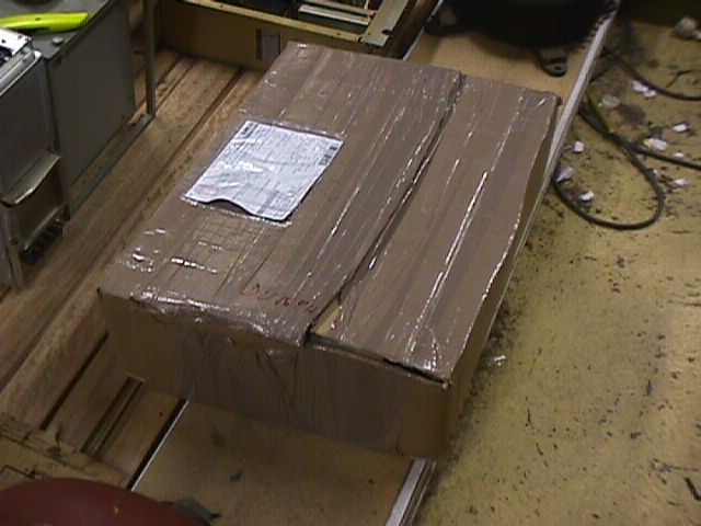
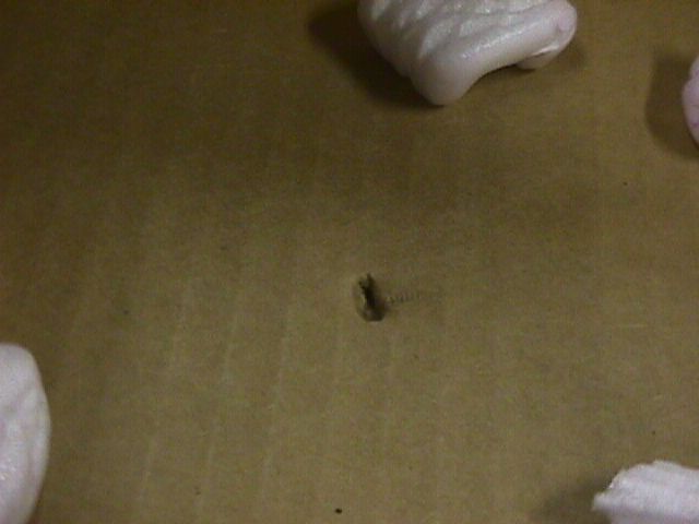
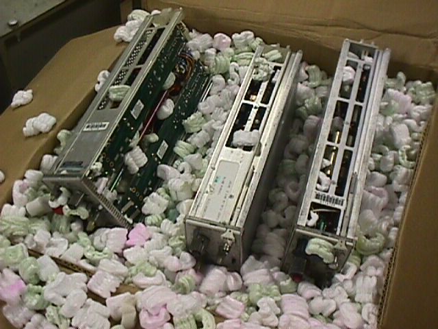
These photos of the unpacking were all taken in 2004 with my first digital camera, a Sony Mavica.
 |
 |
 |
 |
 |
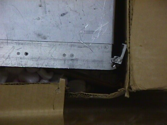
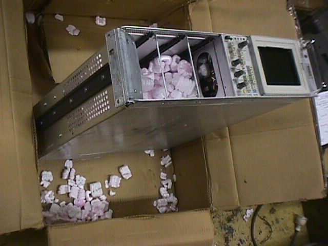
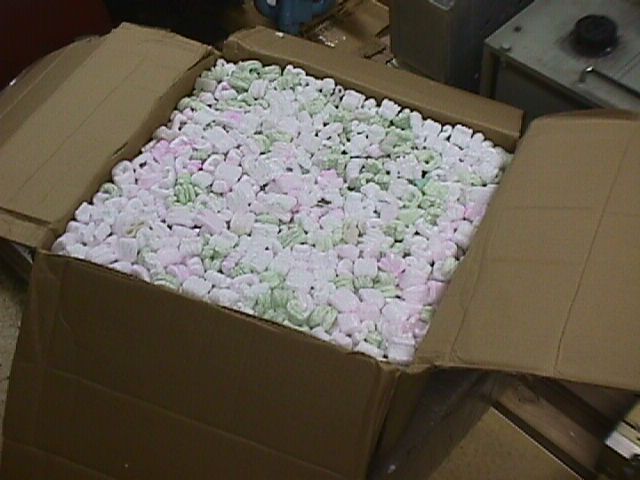
1. He'd cut a box down to fit a US postal size limit. OK I guess, so long as there's still adequate padding inside. Omitting 'Fragile' stickers was unwise.
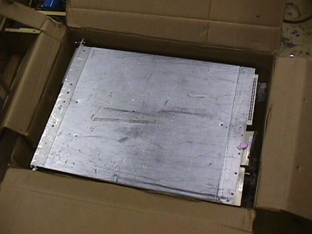
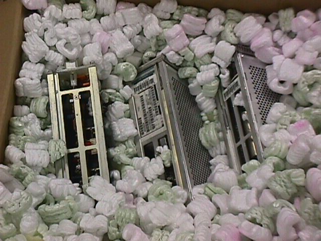
2. Opening the box, an immediate sinking feeling. Wait, where's the padding? A: Effectively there isn't any.
3. So of course the scope is mangled. Multiple damages as the box was tumbled and tossed.
4. RH mounting bracket almost completely broken off.
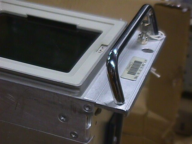
5. Left mount bracket not so bad, but the handle is bent.
 |
 |
 |
 |
 |
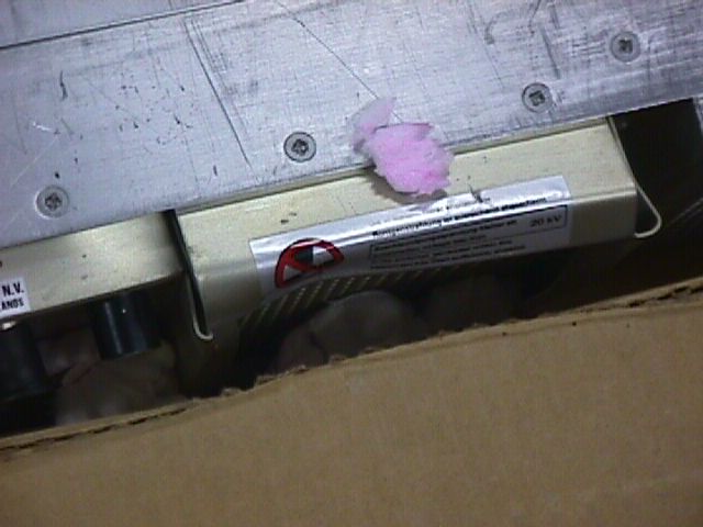
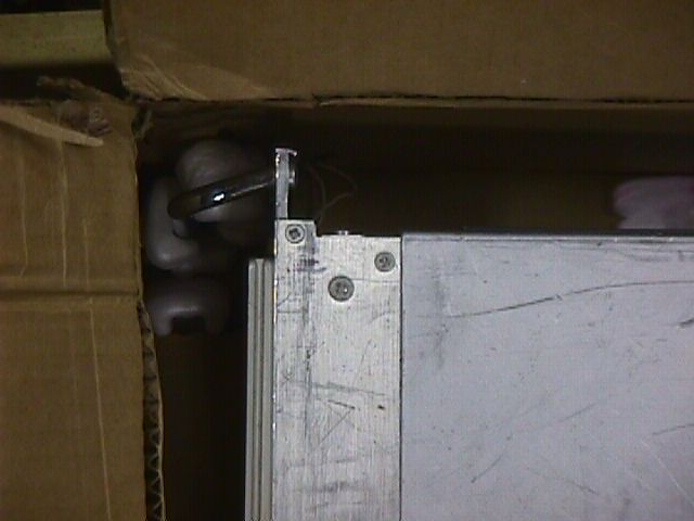
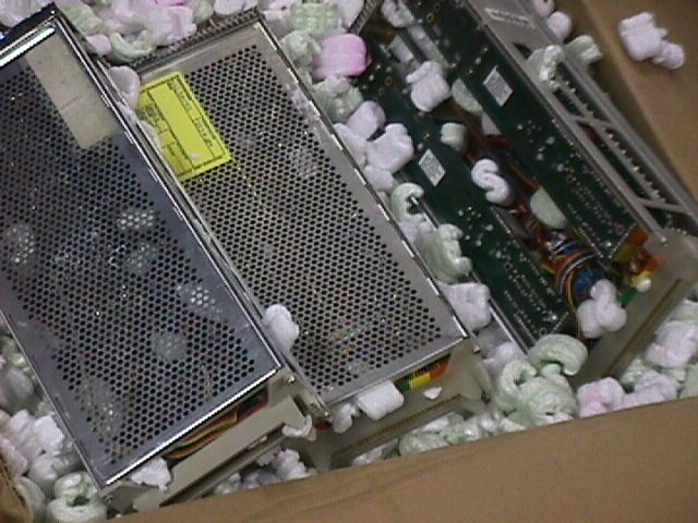
1. Found the stryro peanuts. They've almost all migrated to the safest place for them — inside the scope. That's actually how it was, nothing has been removed from the box. Just a few chips still underneath the scope.
2. Wrecked RH bracket metalwork.
3. Bent end knob shafts and cracked plastic knob.
4. Bent LH handle.
5. Rear metalwork, nothing left unbent.
 |
 |
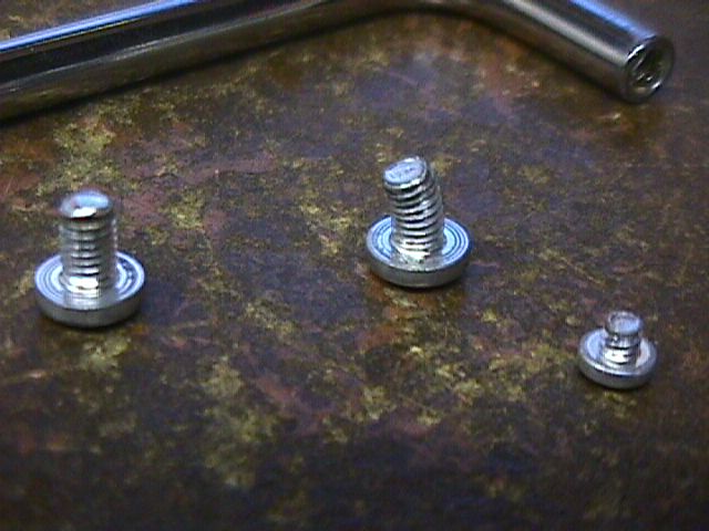 |
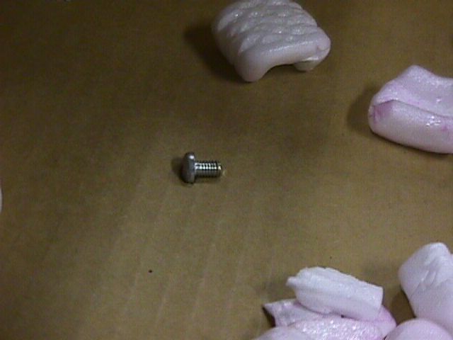
1 - 3. Screws that were broken loose in the box.
 |
 |
 |
 |
As you can imagine I was cursing the seller. Also worrying about the modules, which he'd sent in a separate box. That arrived on the 16th, and wasn't quite as bad as I'd feared. I'm glad he had separated them from the scope, but putting them loose against each other in a tub of styro peanuts? Just more of the same extreme incompetence. Very luckily there was no visible damage, apart from their insides being full of styro peanut fragments, same as the scope. What an idiot. Couldn't he even think to put each module in a plastic shopping bag or something to keep the peanuts out of them?
Worse, by this time the listing and ebay complaint interval had expired. I couldn't demand a refund or even give him a negative rating. Didn't receive any reply from the seller. He had an AOL email address; also not very inspiring of confidence in his intelligence. As for the scope's slide rails being only half there, well, it's typical for people selling rackmount gear to just slide the instrument out and leave the rack-mounted part of the slide rail system in the rack. Even when the slides are actually part of the scope, since the mounting screws are spot-welded into the chassis. Such stupidity, and so common.
This was all rather discouraging, so I didn't try to do anything with the scope then. Just stuck it on a shelf 'to fix one day.'
At that time I had no way to deal with the torn apart aluminium bracket mount points, and my metal workshop was an incomplete and disorganized mess anyway. I'd intended to at least try the electronics fairly soon, but then on 5th November another particularly dramatic life-interrupt occurred, that spun everything off on an unplanned trajectory.
Years passed, with major dramas continuing, plus of course the usual endless small-detail time demands.
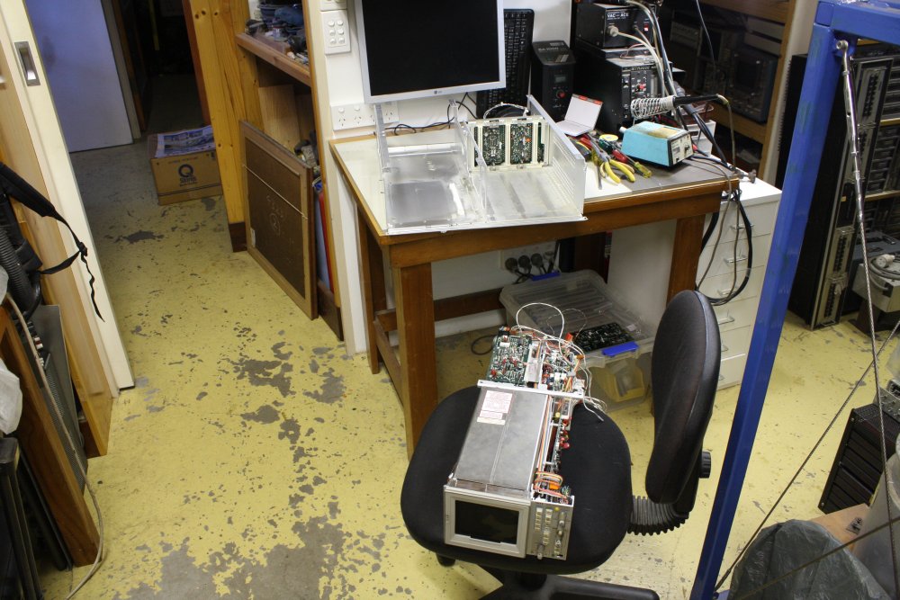
At some point I'd bought a TIG welder, and learned to use it somewhat (not well, just adequately) so thought I could probably fix that ripped aluminium metalwork. Then finally in 2016 an opportunity arose to try working on the 7633.
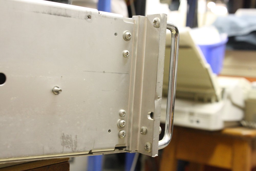
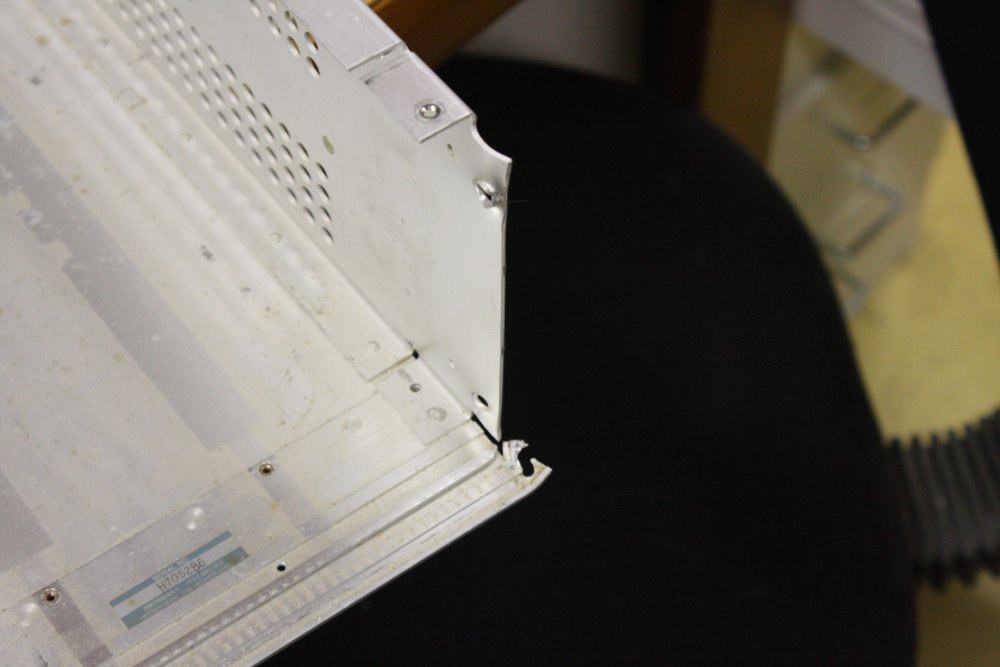
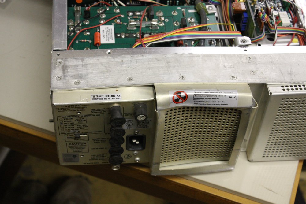
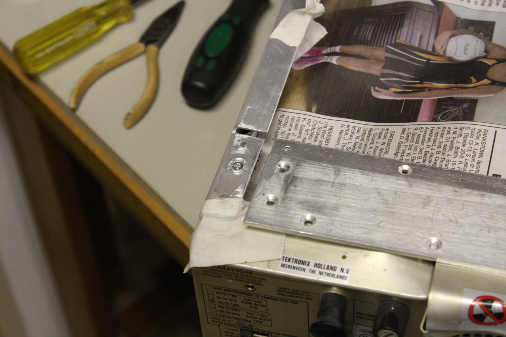
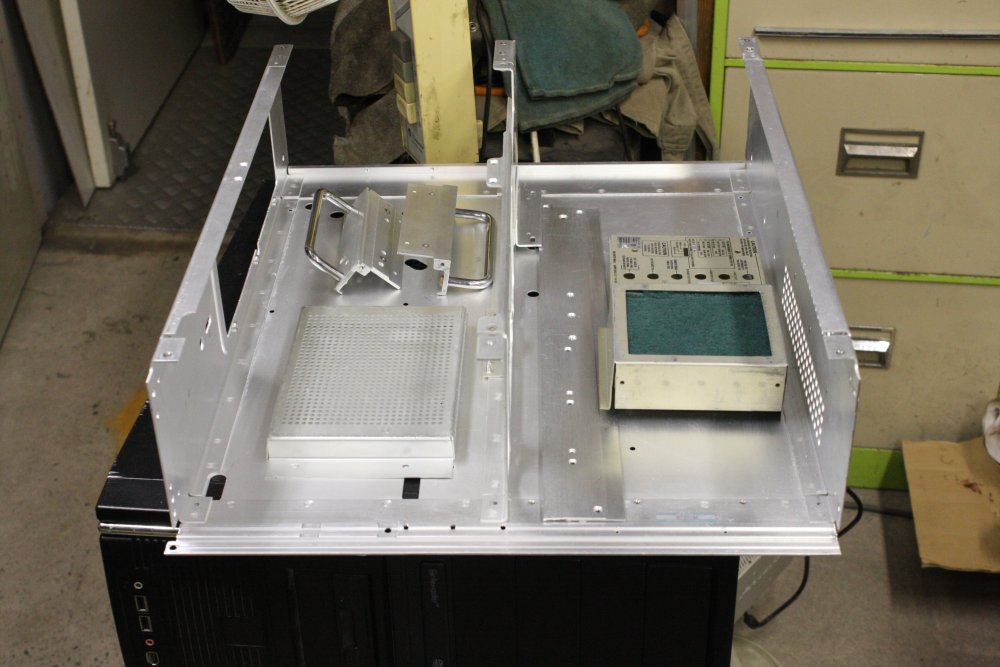
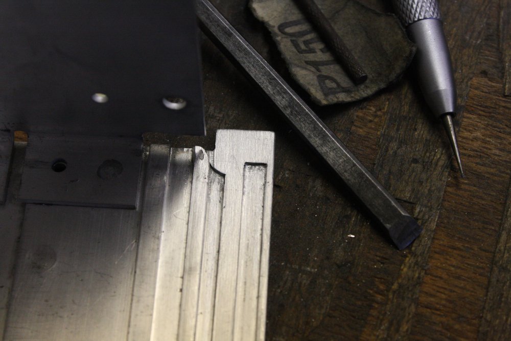
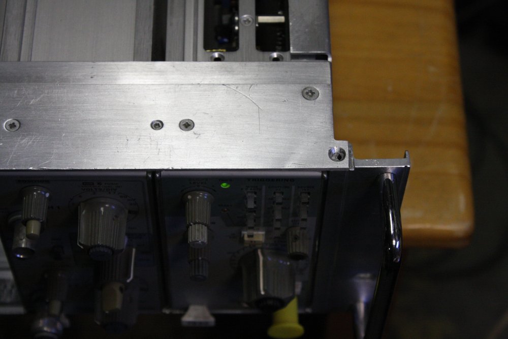
First, a review of the damage to the case, in better resolution:
 |
 |
 |
 |
 |
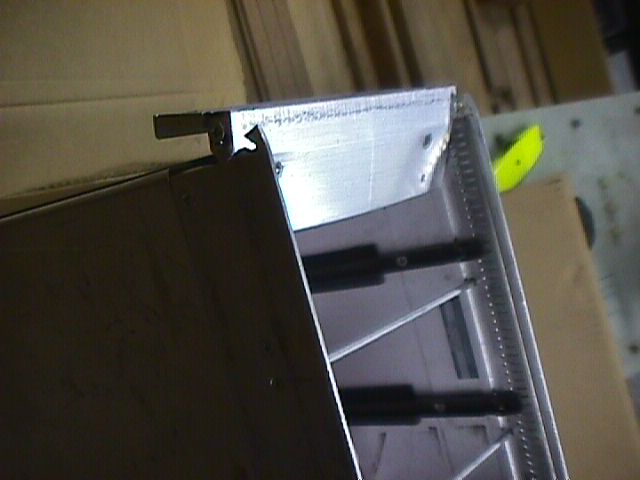
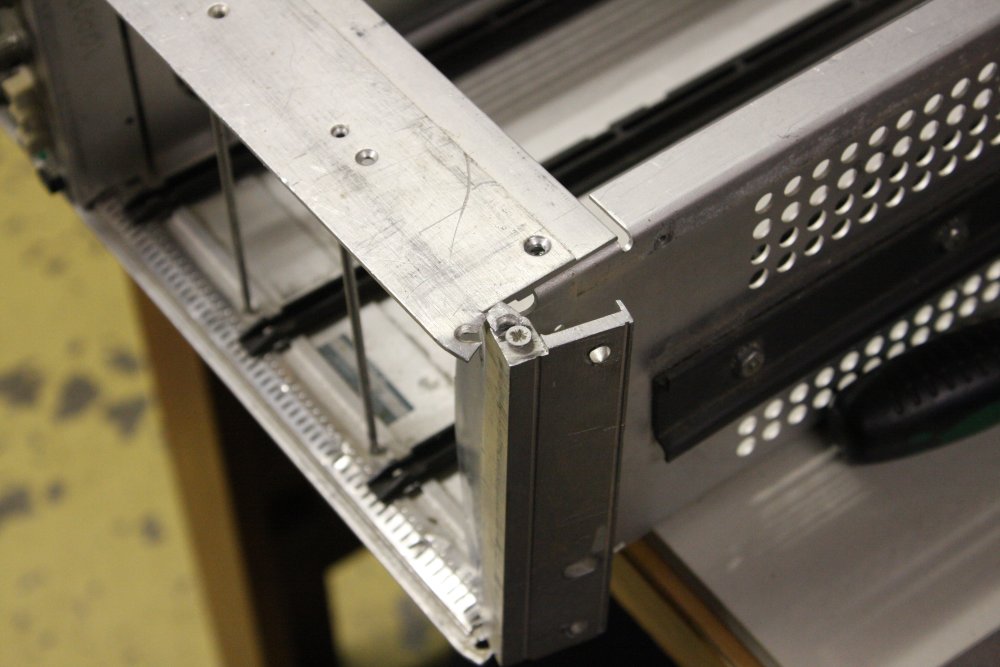
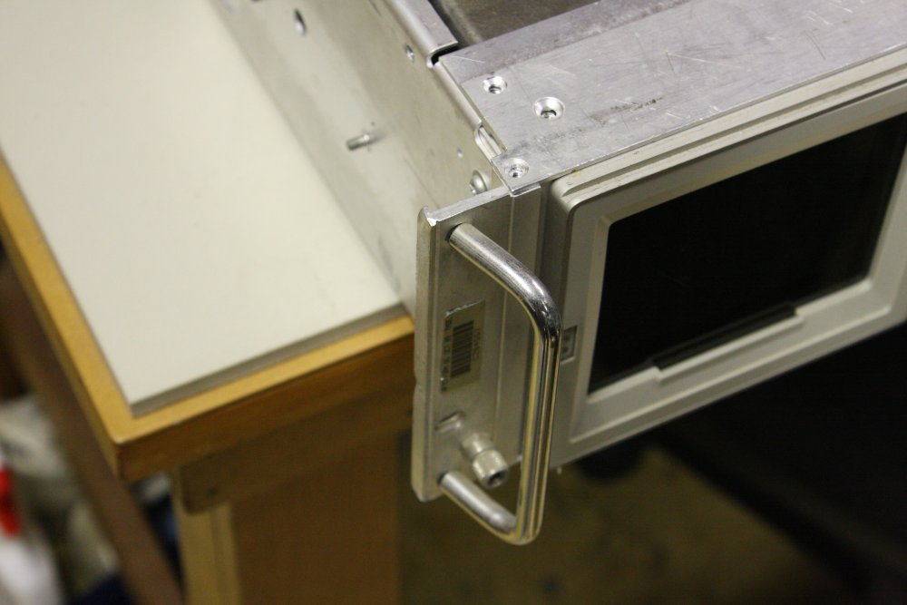
1. RH mounting almost completely ripped off. The attachment points to the main case are destroyed. There is also a handle, it was broken off but I'd kept it separately.
2. LH handle bent, by digging into the aluminium bracket.
3. Also various dings on the bracket.
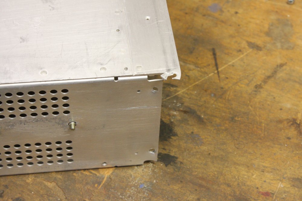
4. RH side of the case metalwork after removing bracket and top rail.
5. Rear metalwork.
 |
 |
 |
There's always one screw that doesn't want to come out. Here one screw on the rear top rail, due to the case distortion, had lost its threads up near the head. It turned freely, but would not start on the lower thread to allow it to be extracted. I had to drill off its head and enough of the shaft for it to drop out. Fortunately the stainless steel nut insert in the case survived.
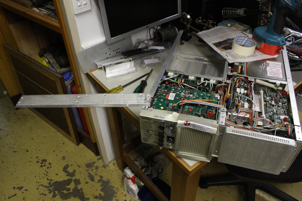
Well, the bits of metal that are merely bent can be straightened. And one of the completely ripped parts is removable so I can work on it separately. But there's that one at lower right, where a little tab on the main case body is wrecked. I'm not going to try welding and machining that with electronics still in the case. (Mainly, I don't want the electronics in my metalworking shop, where metal filings are everywhere.) So the scope has to be completely disassembled, down to the bare case.
There's also the question — should I try the electronics before disassembly, or only after? Before has the advantage that I'll know faults are from the seller and/or shipping damage (and being long powered-off.) But otoh, there could be damage from the impacts that might cause cascading failure if powered on. So I think I'd rather inspect first, trust my disassembly-reassembly to be right, and try it later.
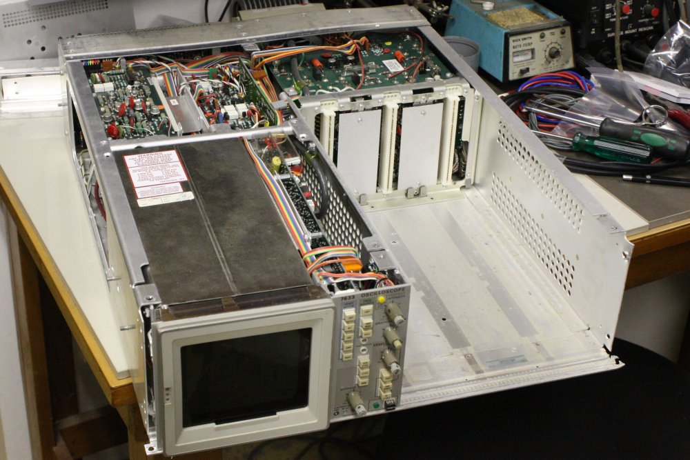
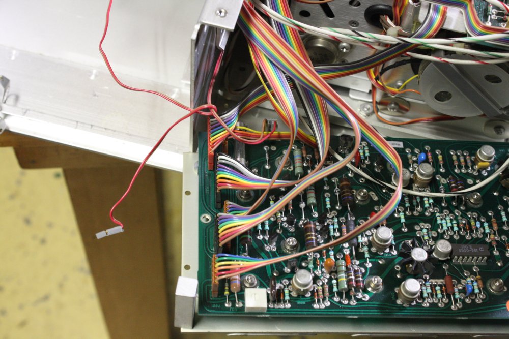
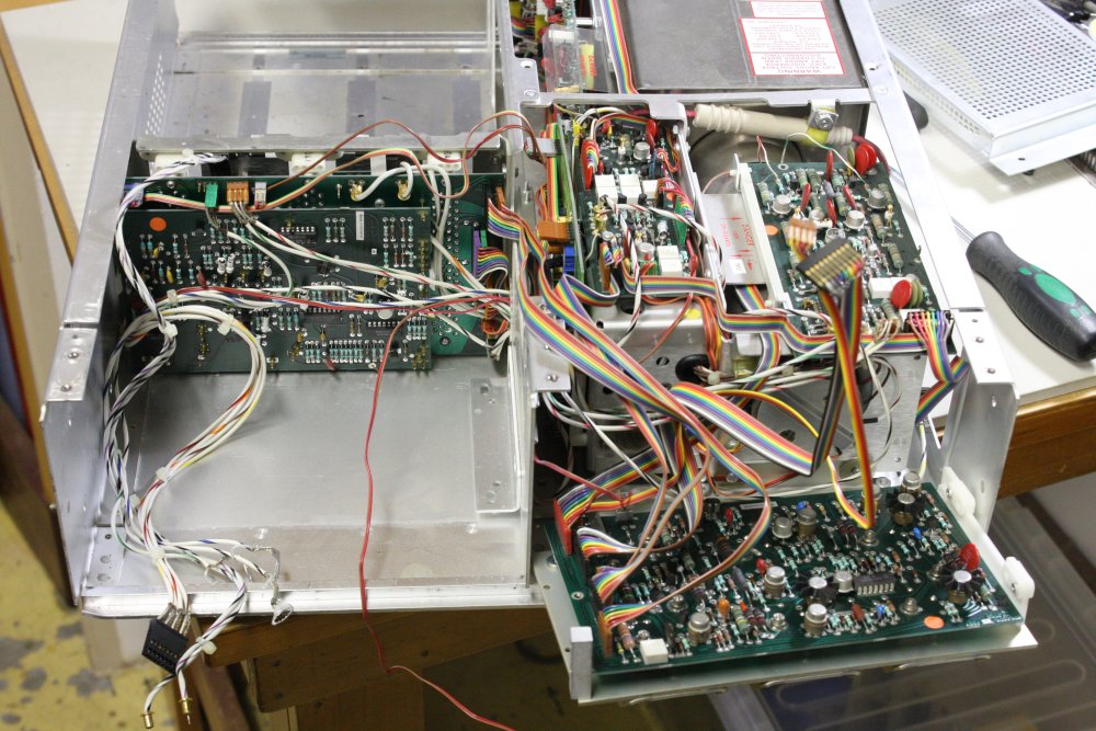
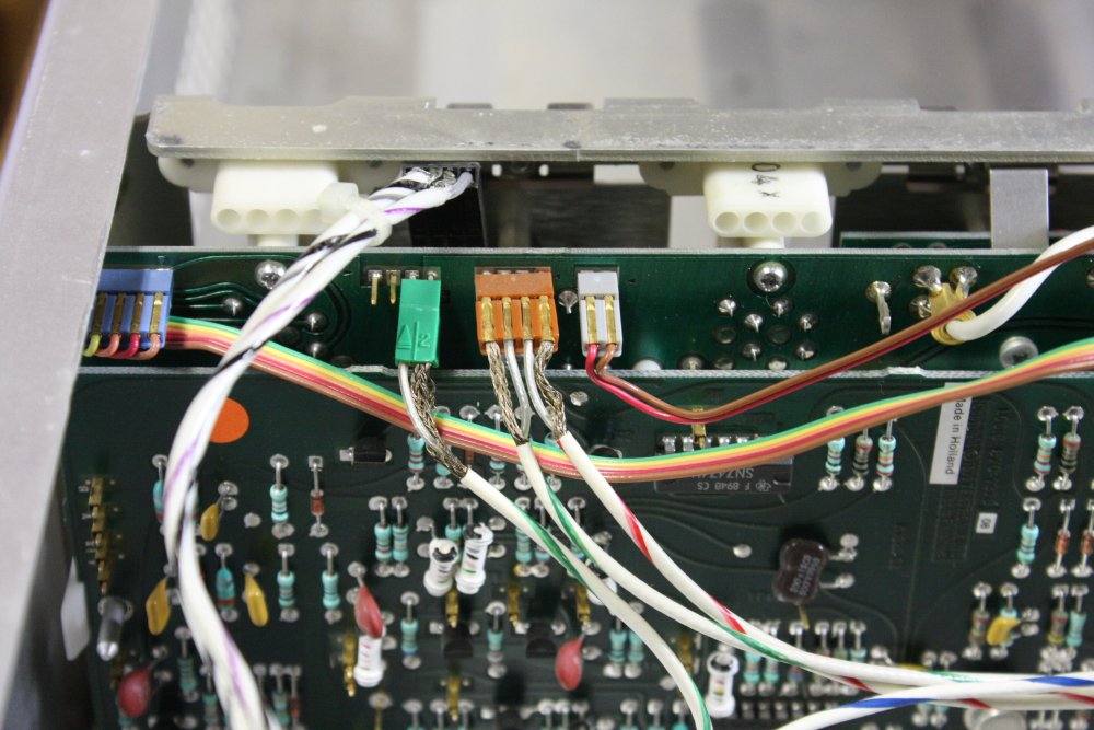
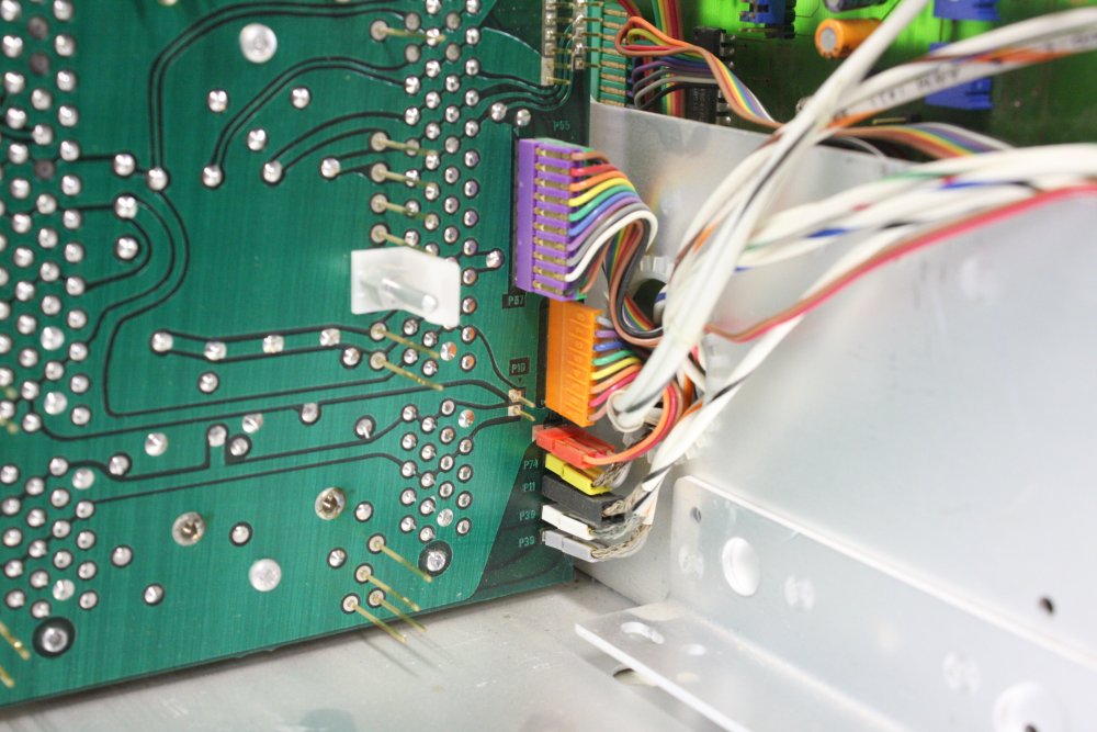
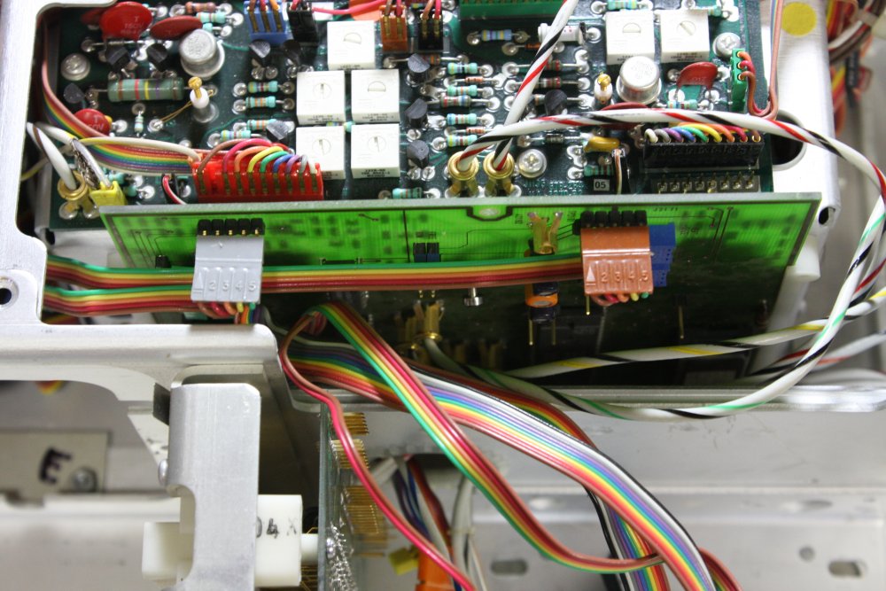
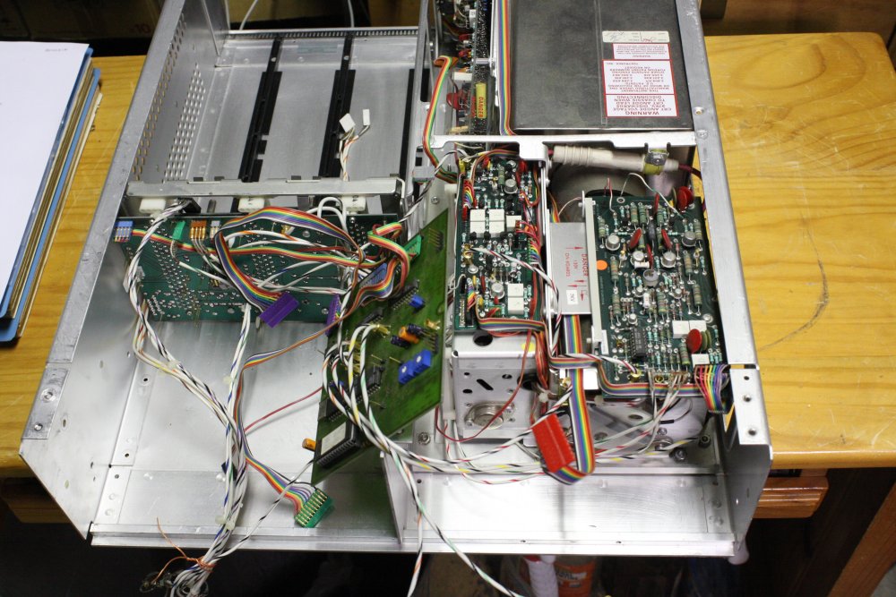
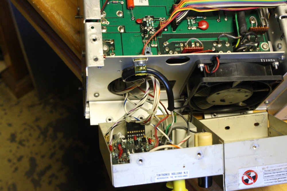
It's densely packed, with a lot of point to point wiring. Taking it apart is easy, it's getting all the wiring back in the right places that will be difficult. I have the service manual (paper and pdf) but that's not much help with wiring paths. So I took lots of photos during disassembly. No point including them all here; only a few examples:
 |
 |
 |
 |
 |
 |
 |
 |
 |
 |
During the disassembly two curious things turned up.
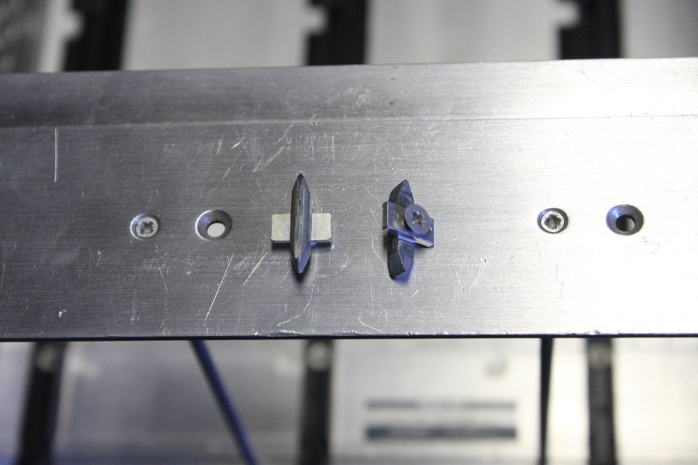
The first was this number roughly hand engraved in the metalwork:
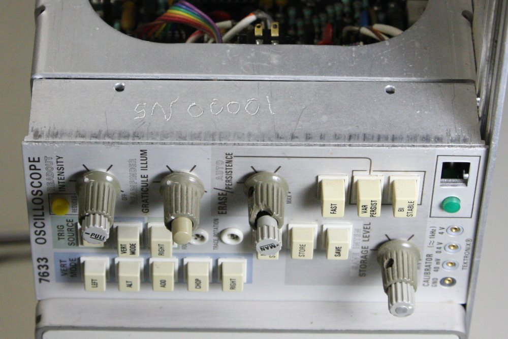
What? Who would have done that? I had never noticed it before since it's in an unusual place, hidden by the modules, and not very visible unless well illuminated.
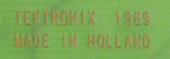
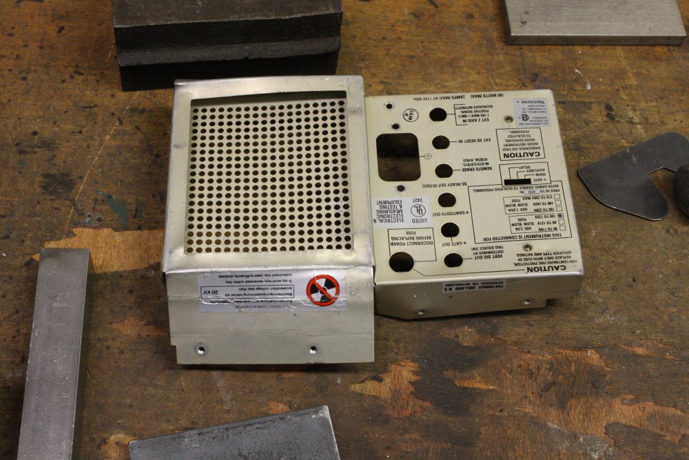
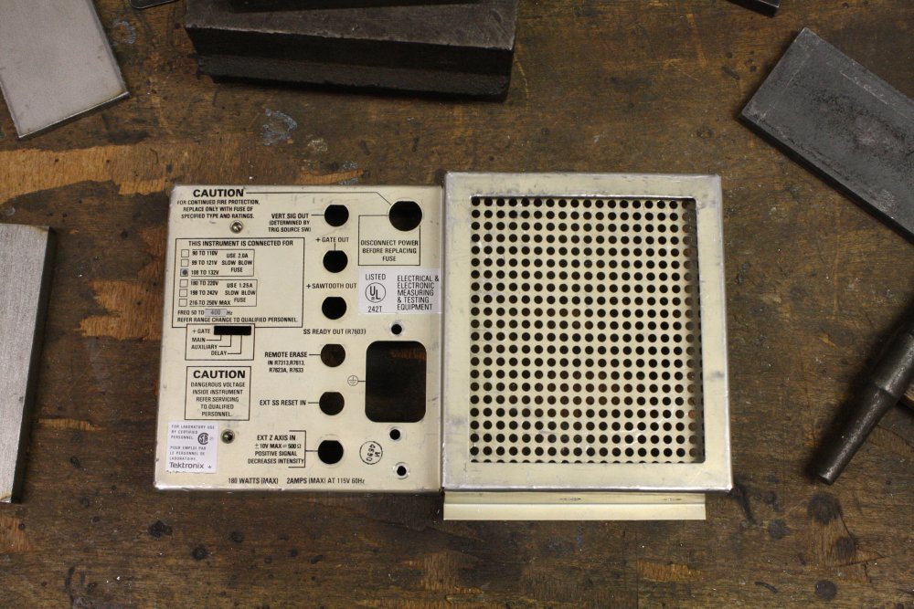
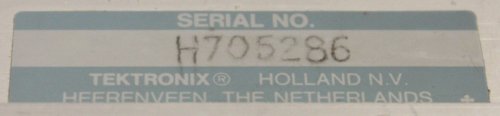 It's (obviously) not the real serial number. That is H705286, and now that I read this label I'm surprised to find the scope was made in the town of Heerenveen, Netherlands. I didn't even know Tektronix had a manufacturing facility outside the USA. Google: they did.
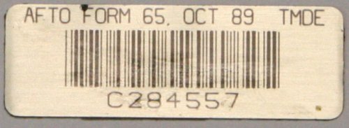 It's also quite unlikely to be an asset number assigned by a company. There was this asset tag on the scope, that I'd removed while cleaning the metalwork. Visible in the original scope unpacking pics.
"AFTO Form 65. OCT 89 TMDE C284557". This scope was made in 1989 (we'll get to that) and whoever AFTO are, being big shots enough to have their own photo-anodized asset tags, they probably didn't buy a second hand scope.
It's amusing that urbandictionary.com says AFTO means "Apart From The Obvious". Also, if a later owner wanted to mark an asset number of their own, why didn't they peel off the AFTO tag? And why would any asset number start with "SN" and be "00001"?
So who marked this "SN00001" and why? Rather curious, but still — someone clumsily marked a number on the case, so what?
Don't forget it though, Mr Chekhov never mislaid a gun. This whodunnit may be solvable later.
The second surprise was really odd. If you are reading this because you know and love the Tektronix 7000 series scopes, then you probably clicked on all the disassembly thumbnails above, and already noticed it. Since then you've been thinking what... the... f*ck? or thought bubbles to that effect.
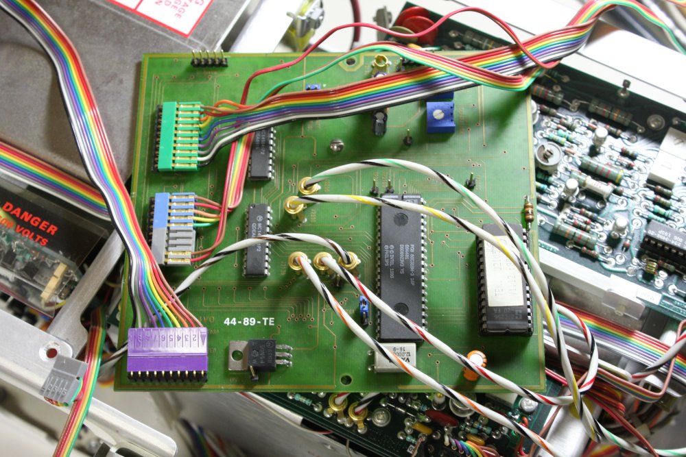
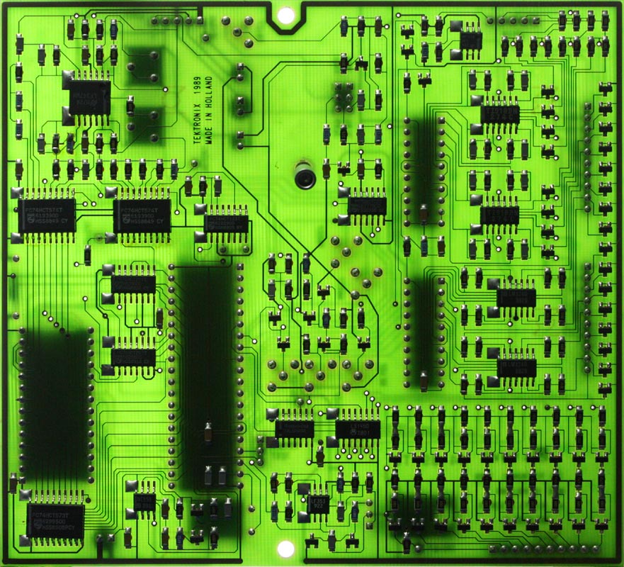
No, you're not hallucinating. There is a PCB in this Tektronix 7000 series scope with surface mount components. Which till seeing it myself was something I never imagined I would see. The 7000 series scopes were designed by old school engineers, for whom it was through-hole or nothing, since for most of their careers that was all there was. The 7000 range began production in 1970 and these guys would have already been experienced engineers mid-career. By 1989 they'd be pushing retirement if not already gone, so I can imagine how they'd feel about adopting new-fangled fads like surface mount. Offhand I can't even think of a single (other) example of Tek 7000 circuit board layout that wasn't done manually with film and tape. No fancy CAD for those guys, they probably didn't trust it, if they were even aware of it.
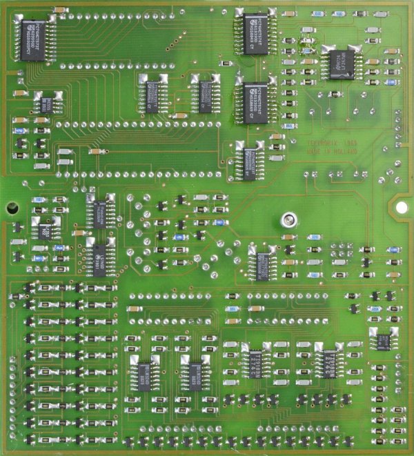
Surface mount and CAD layout.
The PCB text says
Some date codes on these ICs are: 8836, 8849, 8901, 8905, 8914.
Meaning the board was made no earlier than the 14th week of 1989. Sometime in April, or later.
There's something else extraordinary about this board too. Can you spot it?
Hint: any experienced electronics engineer will be feeling quite ill after even a cursory glance. Possibly turning the same colour as the fiberglass resist. And no, the colour isn't it, green is standard for PCBs and nauseous engineers.
But I'm not going to spoil the surprise. First I have a broken chassis to fix.
 |
 |
 |
 |
 |
Cleaning, and figuring out approaches.
 |
 |
 |
 |
 |
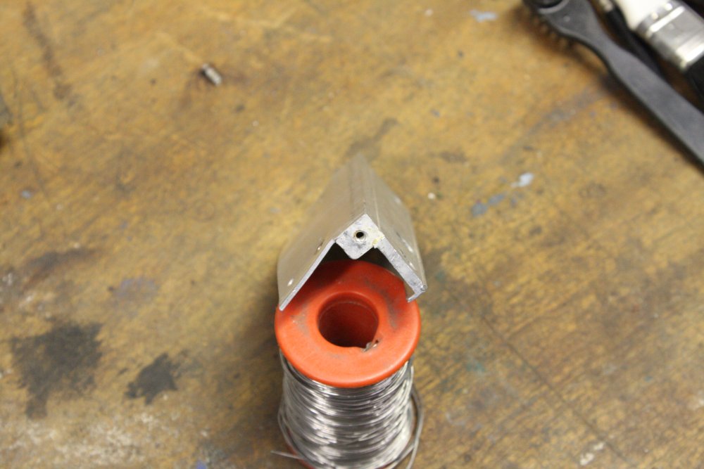
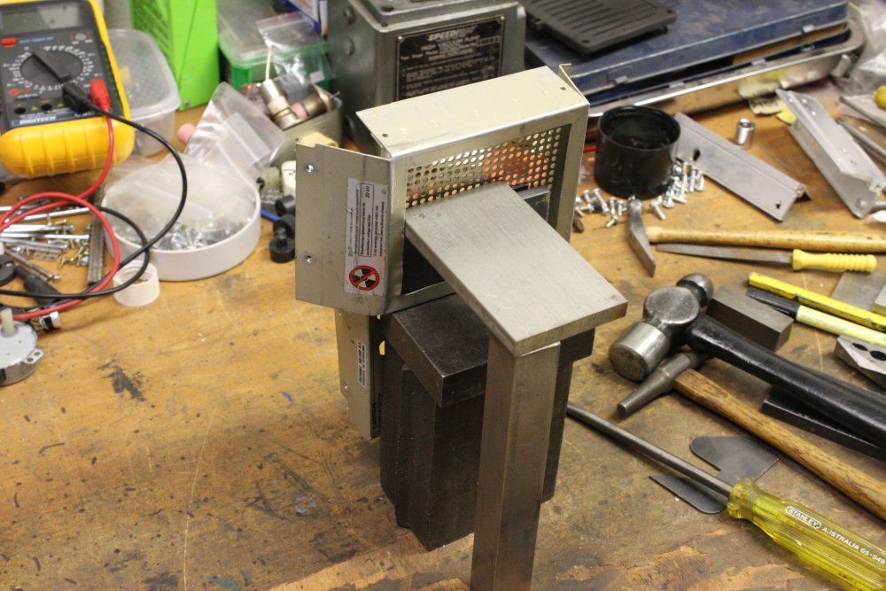
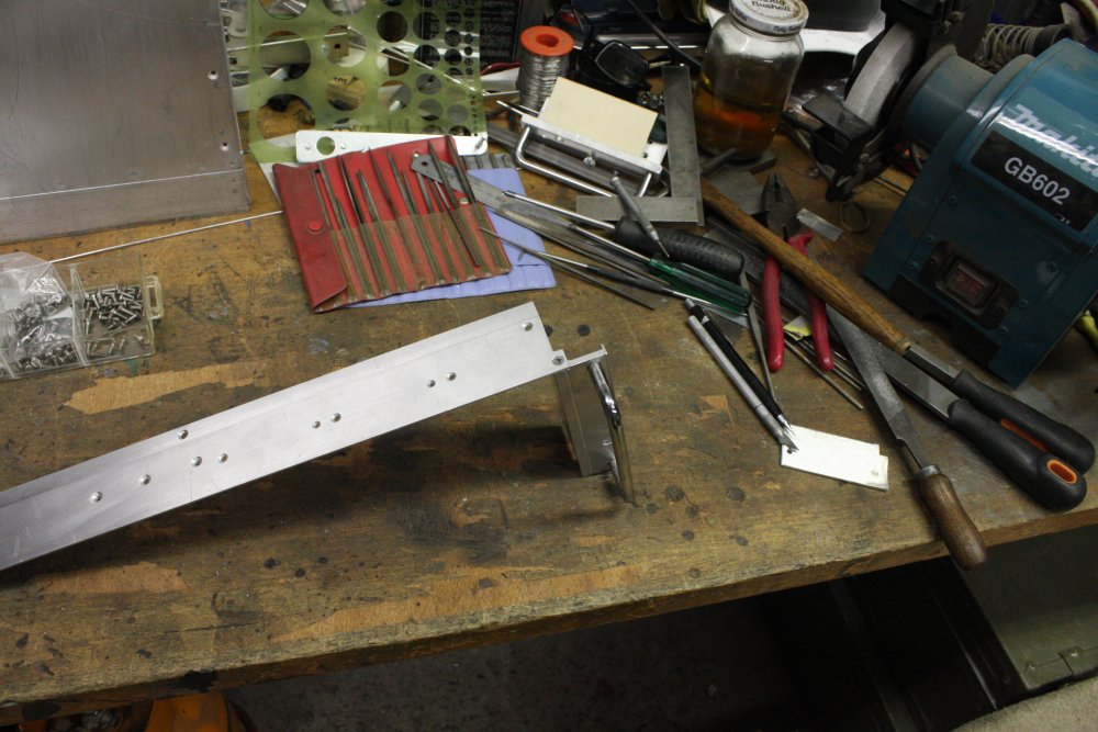
Start with this thing. It's difficult because there's that grill set back from the flanges, and spot welded on. Can't remove, so have to work around it. Lots of fiddling with wedging in backing blocks and tapping away at stuff that could be straightened with one good whack, if I could get at it cleanly. The grill and flange is supposed to hold a dust filter.
 |
 |
 |
 |
 |
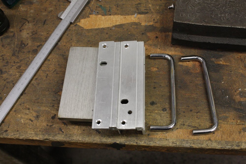
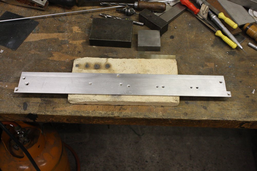
The chromed steel handles didn't bend, they just bent the screws and dug pits in the aluminium rack brackets. The easiest remedy was to make the 'pits' uniform around the screw holes. A little touch with an end mill.
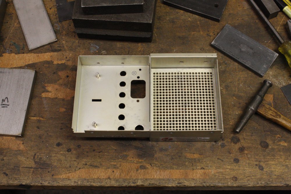
Pic 5 is all the bent bits straight again. And those mangled tabs cut cleanly off.
For dust filters I find kitchen scourer pads ideal. The large size ones can be cut down to fit.
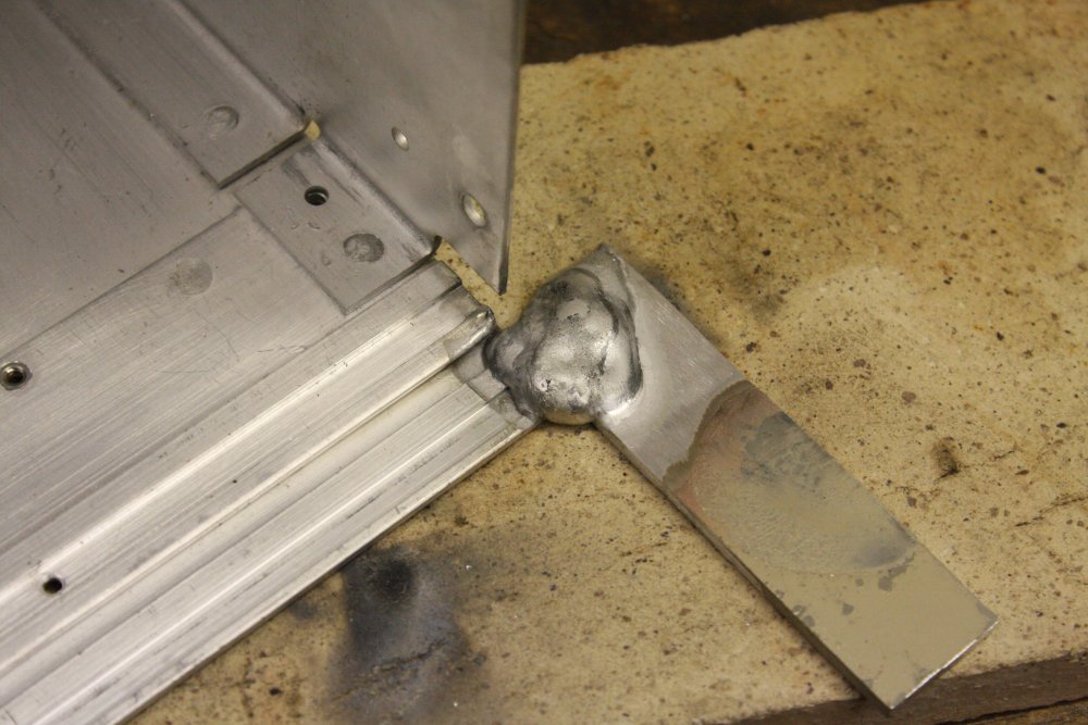
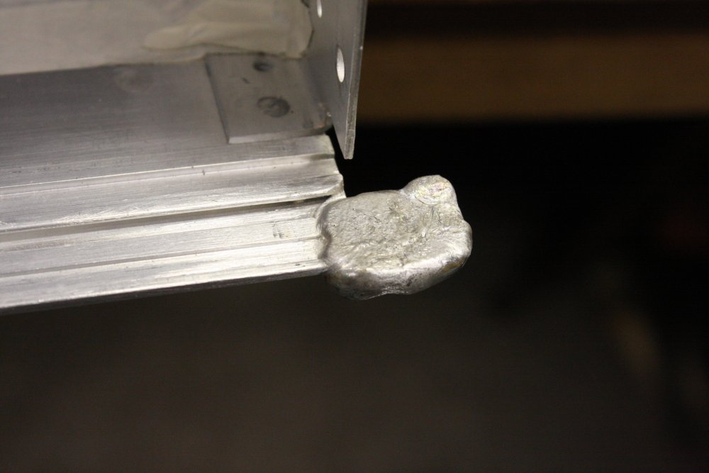
And now for the TIG welding of thin aluminium, to repair those tabs. Before starting I figured I had about 30% chance of completely and irreversibly screwing this up. Didn't actually start writing this till afterwards. I do not trust my TIG welding ... 'skills' is not the right word.
 |
 |
 |
 |
 |
Ha ha... I was so nervous I forgot to take a pic of the initial setup. Never mind, there are two to do.
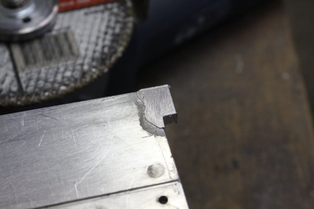
In general the idea is to attach a blob of new aluminium that completely includes the profile of the desired end result. Then cut the excess away. The principle difficulty is the blob boundary, and not having the original form cut down at the junction. Or be completely melted to a gruesome mess or gaping hole, which is very easy to achieve with an arc and thin aluminium. I did a quick practice on some scrap first. You don't want to see that. It wasn't terribly encouraging, but showed the idea wasn't completely impossible.
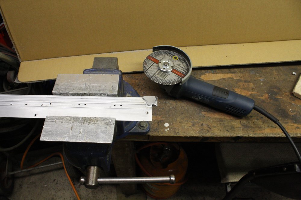
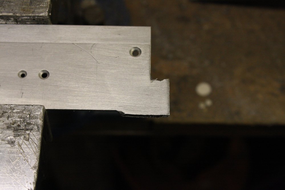
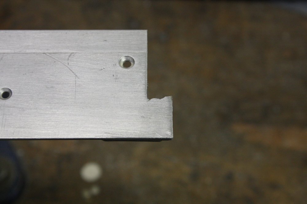
So here in pic 1 I'm at the 'cutting back' stage, using an aluminium cutting wheel in the angle grinder. By which time the sense of panic had subsided enough to remember the camera. The remaining pics are progressively shaping that side to the final tab dimensions. Used the angle grinder till close to the scribed lines, then flat files to get a clean finish. Wetting the file with kerosene and regularly brushing off the filings prevents scoring of the surface with bits stuck in the file teeth.
That was the easy side.
 |
 |
 |
 |
 |
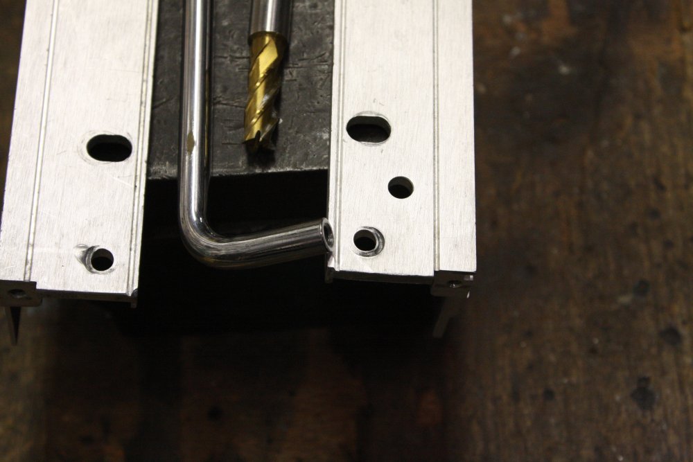
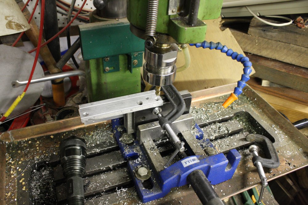
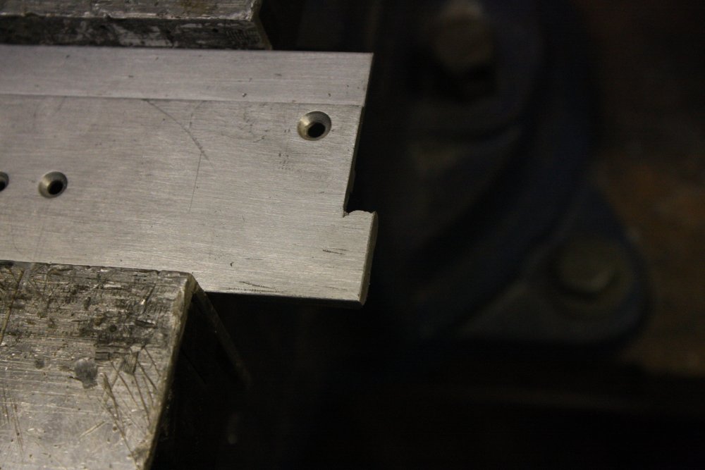
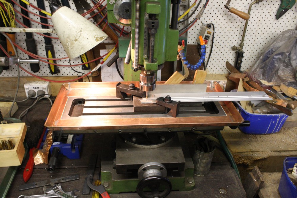
On the other side, there's a profile. And so to the mill.
1. General setup. Why yes I did tidy up the mill and bench beforehand, thank you for noticing.
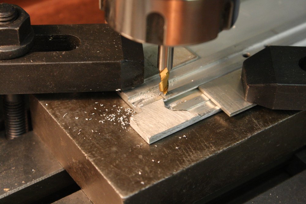
2. It had taken a couple of blobby-tries to get an edge adhesion that didn't sag the existing profile, hence the extended blob. But no matter, it's all grist to the mill.
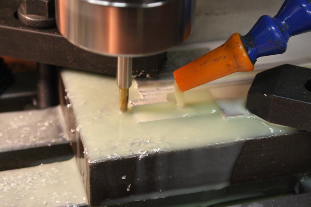
3. Taking off a bit of blob depth, and worried about the thinness of the remaining section, I used cutting fluid.
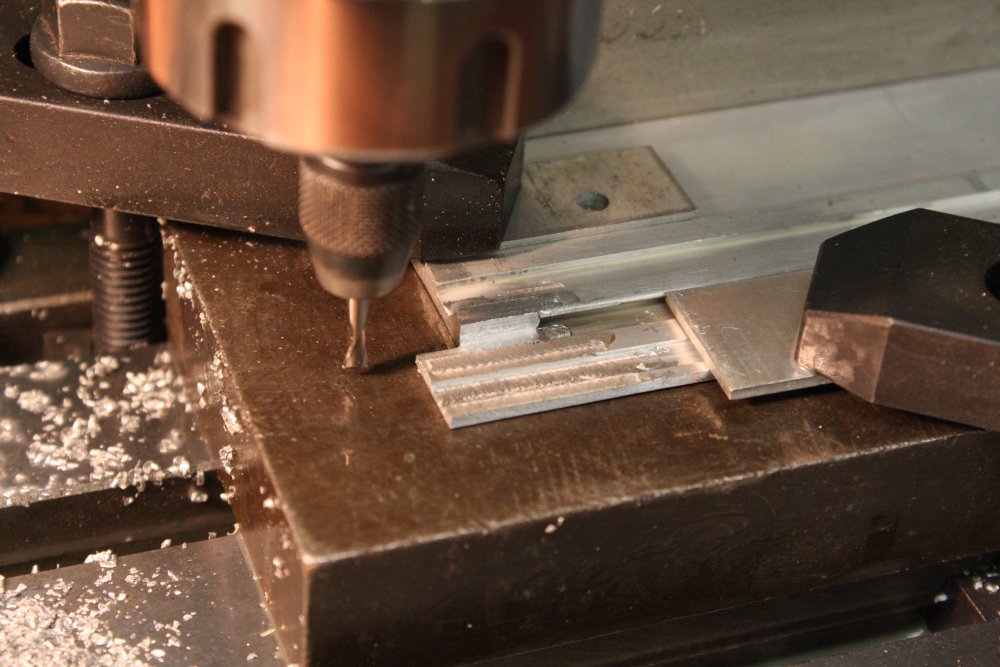
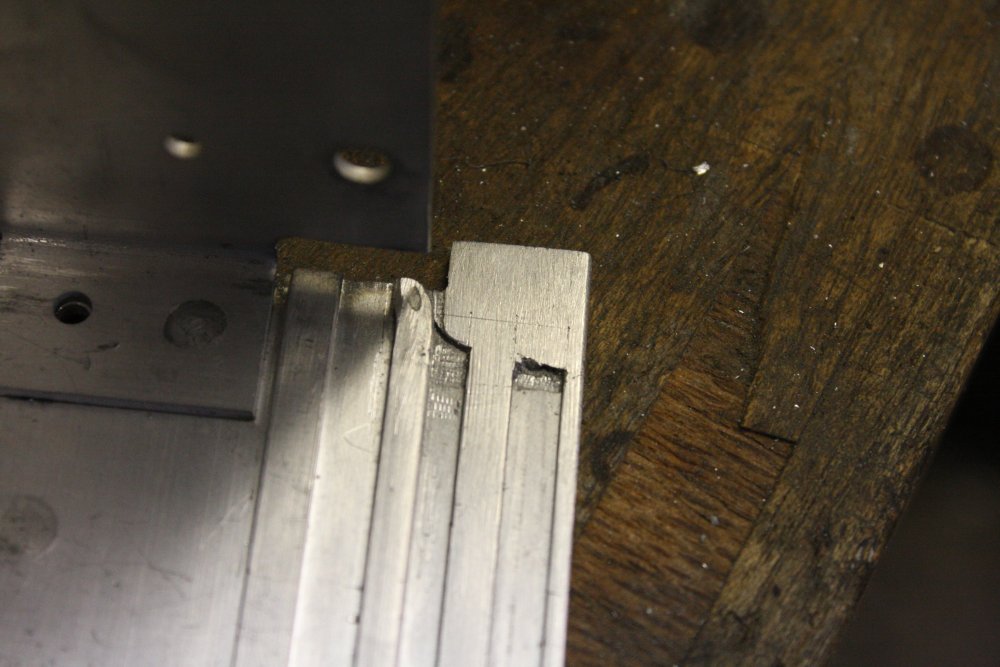
4. Cutting the grooves. The rear one is narrower than my smallest mill bit that fits in the smallest collet, so I used a pin vice in the mill chuck, with a quite tiny mill bit. The centering was poor, but it worked anyway.
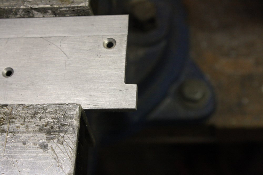
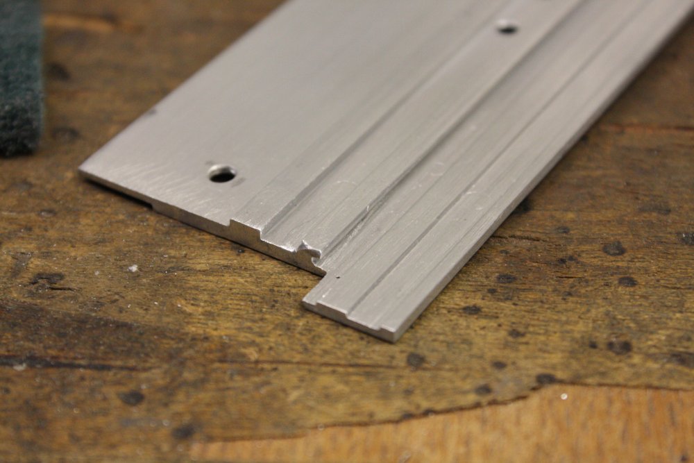
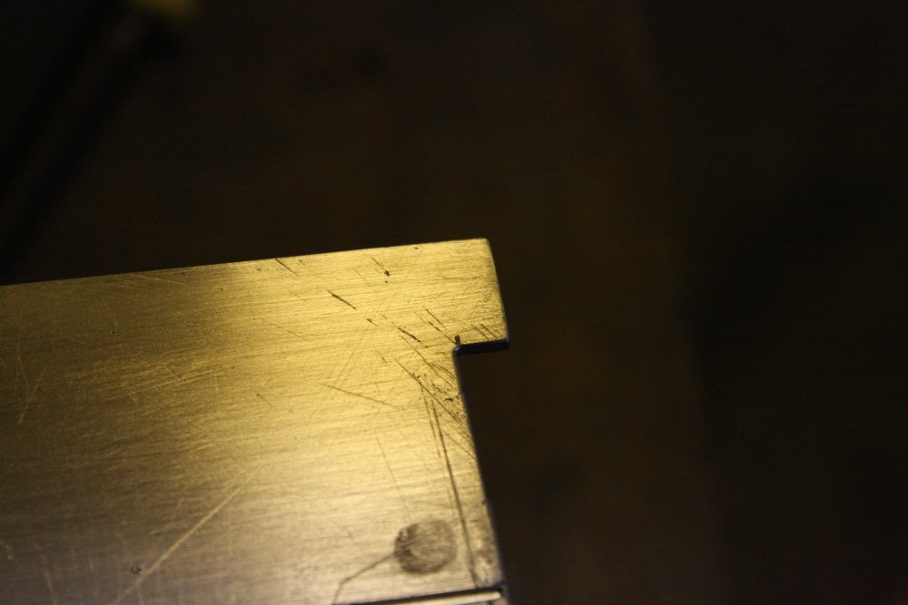
5. End result. I'm happy. The undercut profile I did by hand with a hack saw blade.
 |
 |
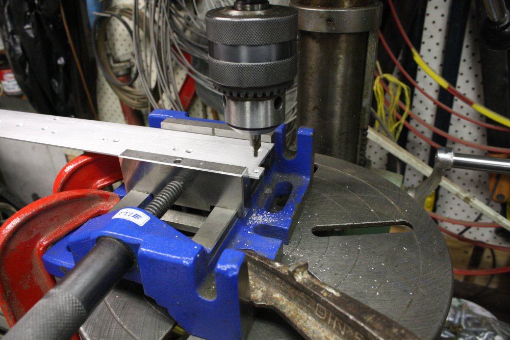
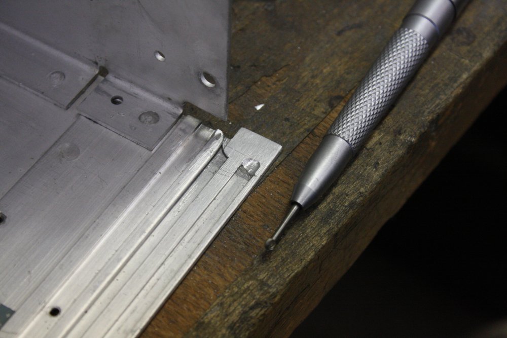
A potential problem with drilling the hole, is that it straddles one of those profile edges. An ordinary drill bit would drift off to the side of the thinner section. So I drilled the hole with a centering bit and everything clamped.
The countersinking partly intersects the thinner side too, so had to be done carefully with a bit of side-push.
 |
 |
 |
 |
 |
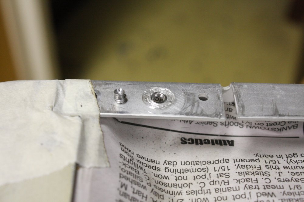
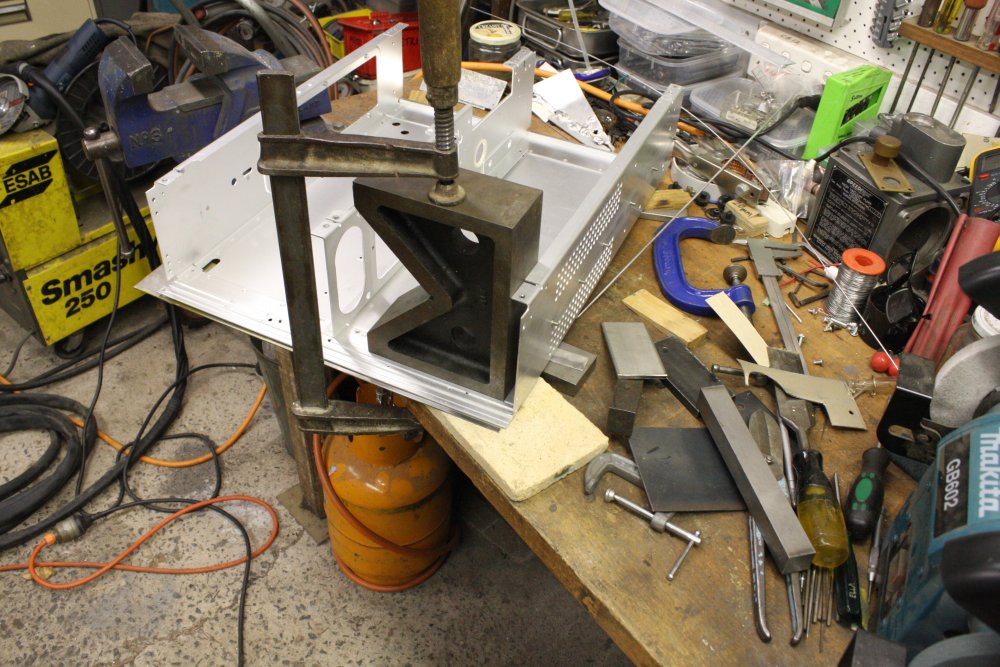
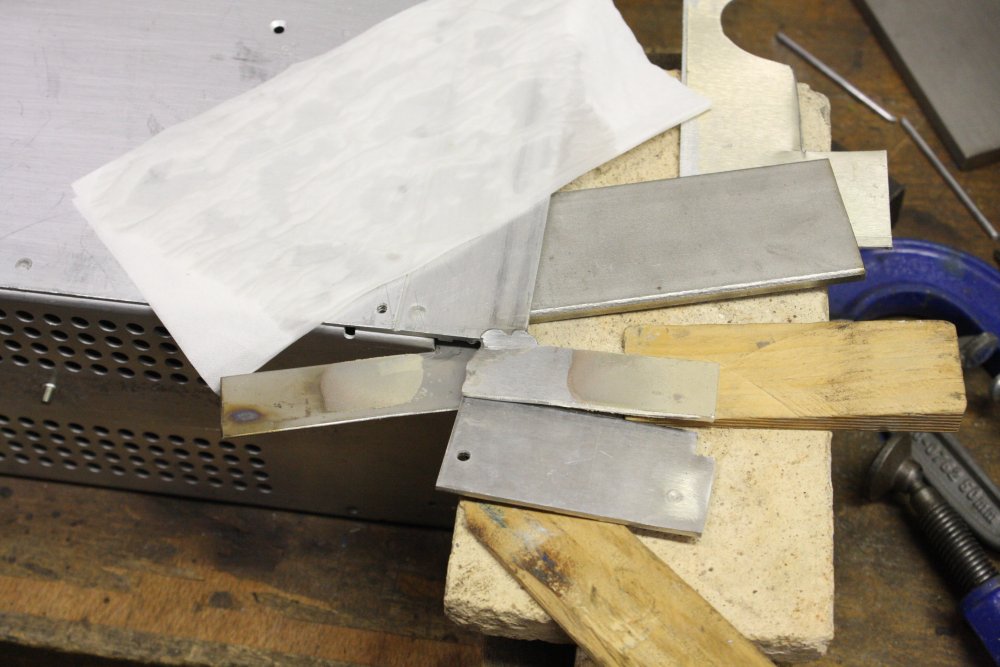
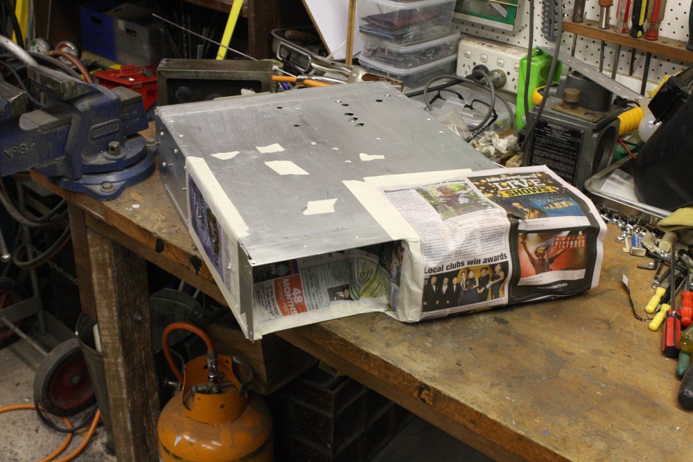
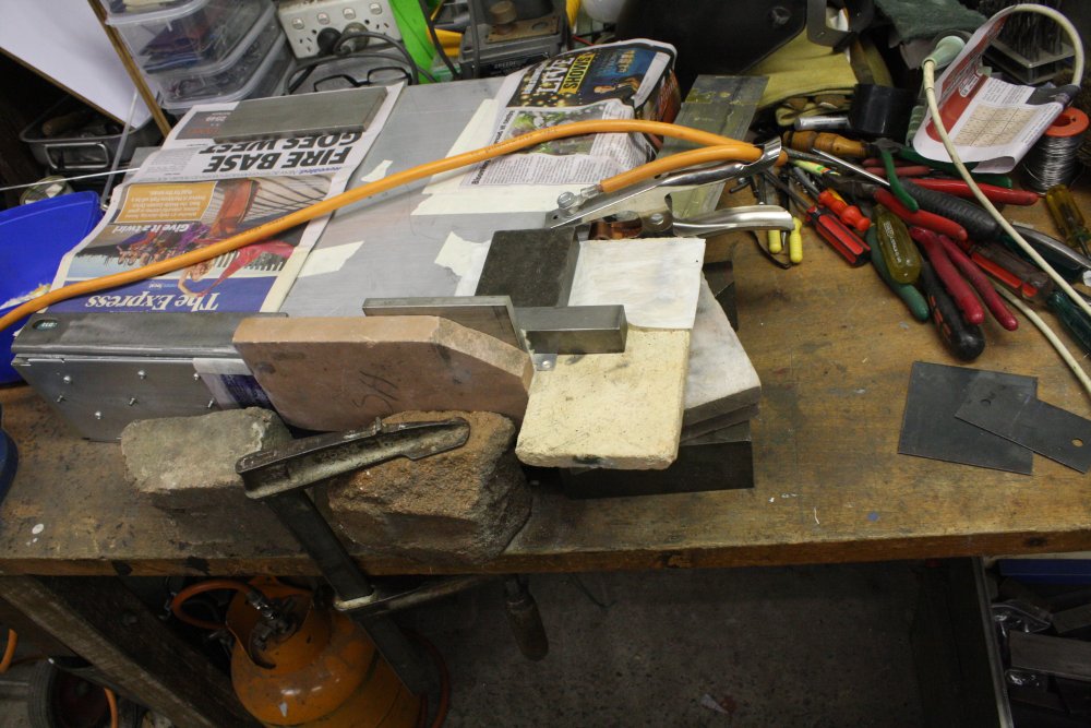
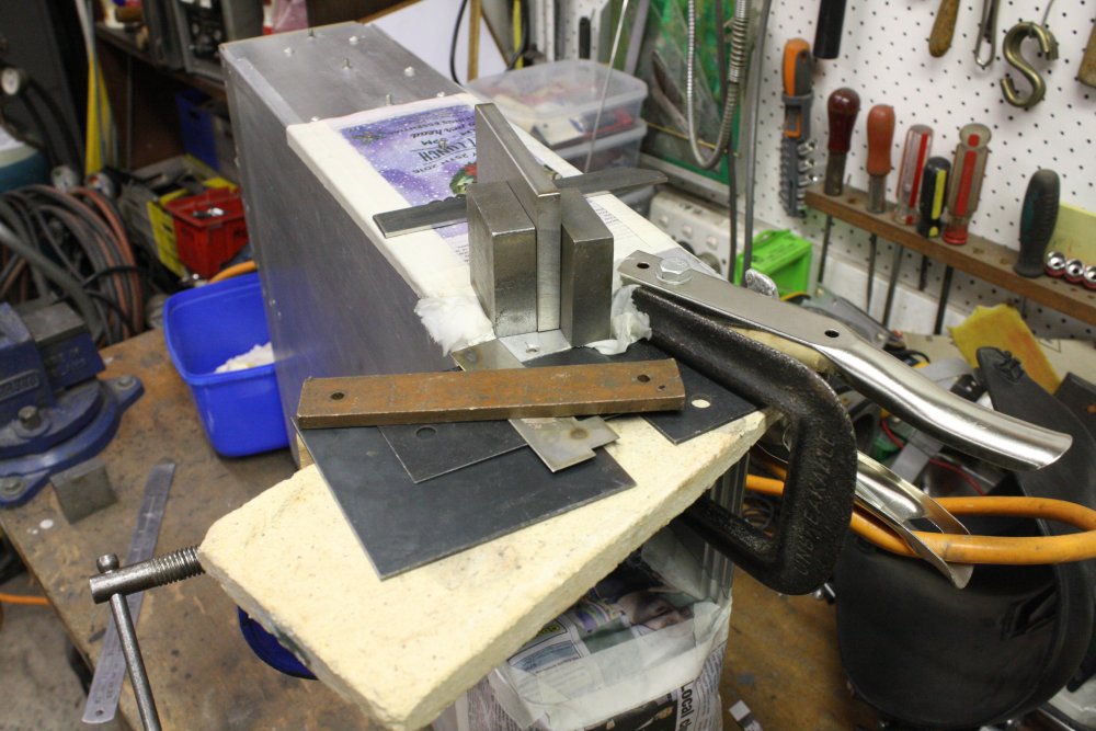
Replacing the lost tab on the bottom frame is a different problem, since the frame upright blocks use of the mill, and also excludes the TIG welder nozzle from some angles that I'd expect to need. Also there's the edge of the upright, which is close to the TIG arc and must be protected from being accidentally melted away. Another important point is that the serial number sticker is close by, and I'd like to not destroy it by heating the metal.
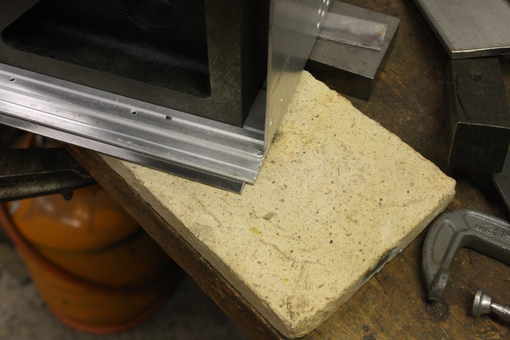
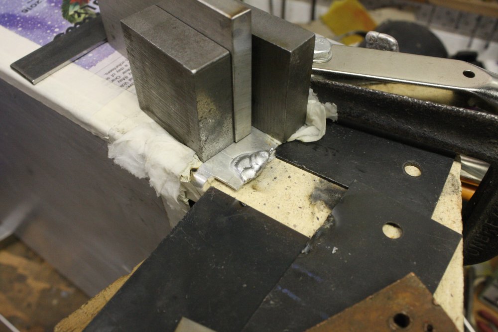
1. Using the big V-block as a heat sink to protect the SN label.
2. I thought maybe by raising the bottom surface on a shim, sag-through of the weld blob might avoid the need to TIG onto the other side later. It probably would have worked...
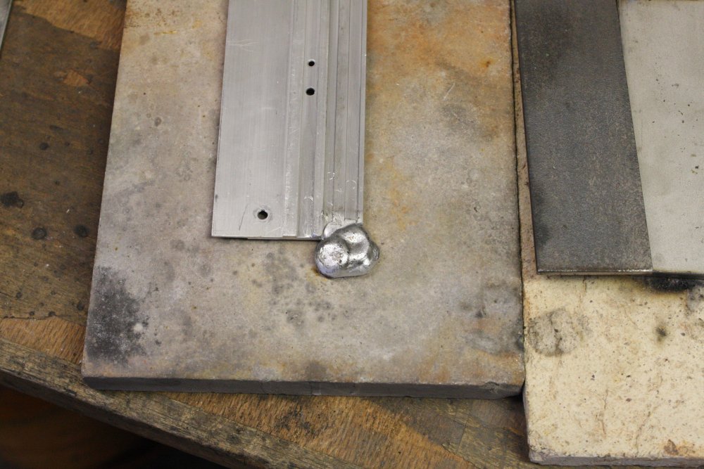
3. About ready to go. Now, should I use a bit of scrap aluminium as a starter, or just build up blob using filler rod? I decided on the first. In hindsight, would have been better with the second.
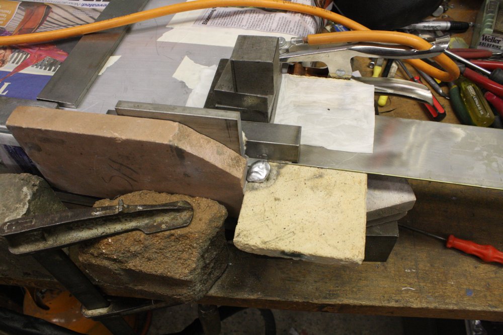
4 - 5. This is what I mean by blob. It may look disgusting, but I'm pleased with it. Neat adhesion at edges, no inclusions, no damage to surrounding metalwork... Hey, that rounded-off corner on the rear profile was there before, from the impact damage. Not my fault, and I couldn't get the blob to join with it without risking damage to the upright corner just above.
 |
 |
 |
 |
 |
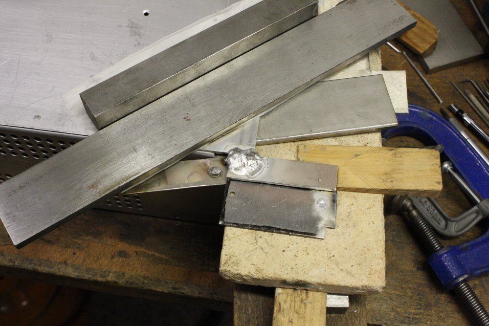
Sadly, the underside of the join still had a remnant crevice. It probably would all be gone when I filed back, but I didn't want to risk finding out it didn't. So cut it away roughly and added more blob. This time for heatsinking I used a wet tissue under steel blocks sitting there with their own weight.
Last pic - Oops, I scored the final surface a bit. Didn't clean the file often enough. Oh well.
 |
 |
 |
 |
 |
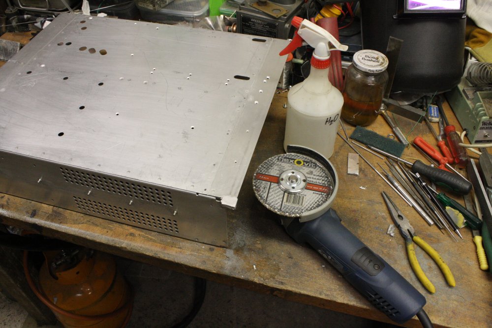
Last and most awkward. Apart from roughing down to nearly the final surface with the angle grinder, it all had to be done by hand. I decided not to continue the slots to the end, to simplify the hole drilling.
1. Marked the slot position. It has to be there, to fit that thin stainless RF-gasket.
2 - 3. Using engraver and a fine wood chisel to form the channel. The chisel for scraping and shaving the surface to final shape.
4. Using the top strip as a drill template.
4. Done.
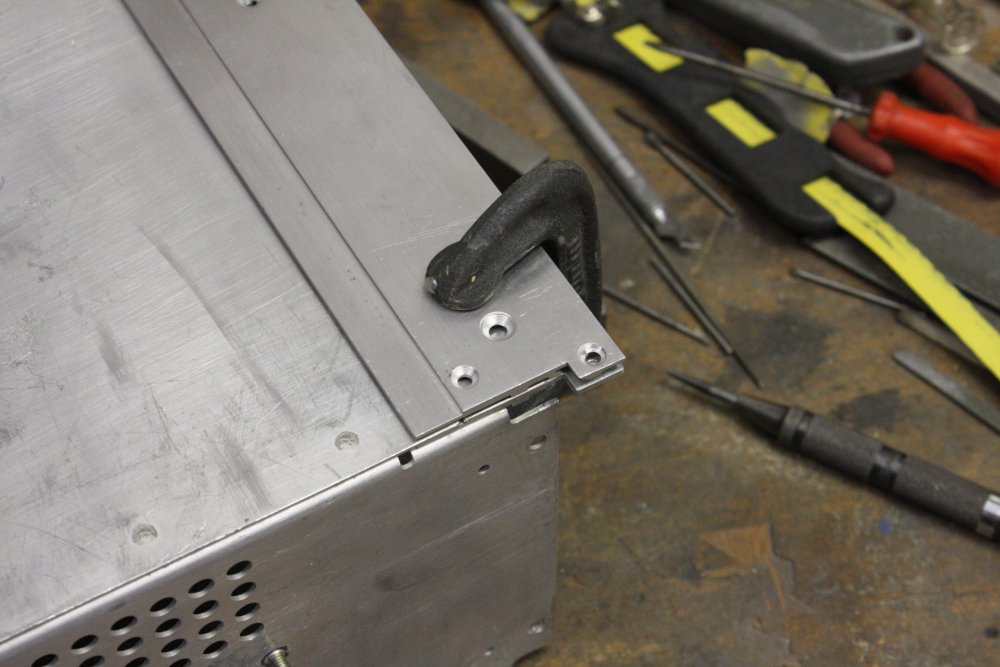
Now to put it all back together.
20160512 Oh for Pete's sake... (aka stupid assumptions)
It's back together, and mostly works. But...
 |
 |
 |
 |
 |
1. I'd started reassembly a while ago, then had to put the scope aside for other chores. At that point I'd been slightly stuck with the readout board; not sure where a couple of cables went. (No matter how many photos...)
After the solar panels, fixing a lawnmower, yard maintenance and clearing a yard junkpile, back to the scope. This time it seemed simple, not sure why I was confused before. When about to install the main power supply module, it occurred to me - did I ever convert this to 240V? It came from USA so was originally 110V. A: No! I didn't. Lucky I checked now. That's one stupid assumption I didn't make.
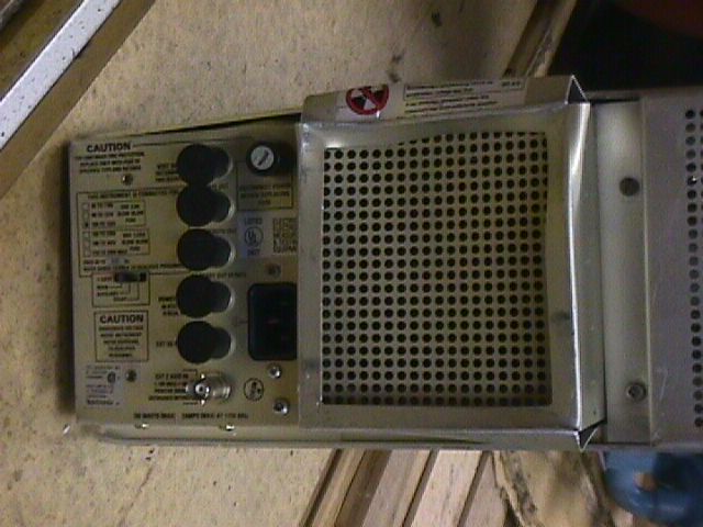
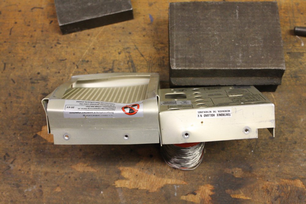
2. Preparing to install the power supply module, which goes in the empty space here. It has a bunch of large electrolytic caps, and it would be nice to test them first. But how? They are all cans with 4 or 5 pins each. That's a lot of desoldering. Also the large transformer is direct hard-wired to the PCB. It would be a massive pain to disassemble this. So I think I'll skip that, and just check ripple later. Can always take it out again.
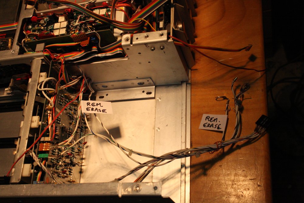
Speaking of which, it would be nice to be able to remove the power supply with the rear panel connector board attached. To save having to unsolder and remove 6 BNCs and the rear panel mains wiring. Checking the destinations of wires from this set, all but one can be easily unplugged at their other ends around the backplane module. The exception is the 'remote erase' coax. White sheath with blue stripe.
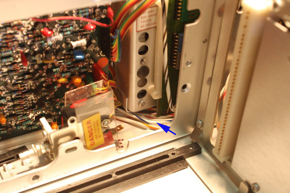
3. There it is, in pic center, disappearing under the CRT assembly. It goes in a wire-tied cable bundle up to...
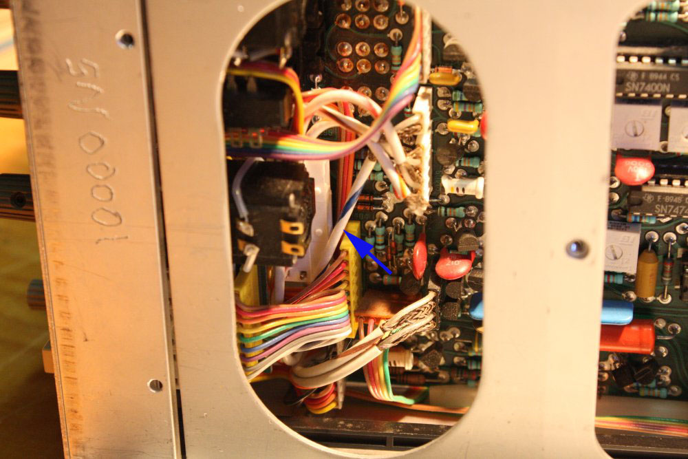
4. The front of the Storage PCB, just behind the front panel controls. Bah. It could be untangled from that lot and routed in a way that allowed its removal easily, but not now.
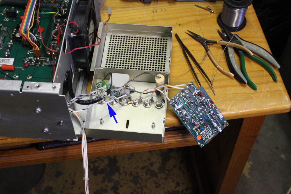
5. Resoldering all the wires at the back panel. After tightening all the BNC nuts with a socket wrench, I screwed it all back together. Just assuming all the BNCs had stayed correctly keyed in their non-round holes. After completing everything I finally bothered to look at the back panel. One of the BNCs had rotated and wasn't sitting properly in its hole. Guess which one? Right, 'remote erase'. Crap. Take it apart again, desolder that coax so the socket wrench can reach the nut, redo, reassemble. Grrr...
 |
 |
 |
 |
 |
1. These little screw-on guides are for aligning the modules. There was one missing when the scope arrived, and I've never found a spare. Something for my 'want' list. Or, I could get around to hunting/asking for one, which would probably be more effective.
2. When nearly finished assembly I had one plastic cable clamp and its screw left over. Huh? Wheeeere did that come from? Obviously for one of the mains cables, but all the cable clamps I remembered were all in place. I carefully checked all the photos... nope, no sign of it. Finally I figured it out. This. It was the very first thing I'd undone inside the scope when starting disassembly, and just before I started taking photos.
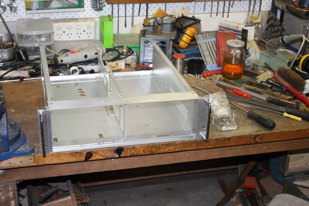
3. All back together! Now for the moment of truth. Actually, several truths, including was the scope originally working as it arrived years ago? plus did it die from sitting idle for years? as well as does my disassembly-reassembly suck?
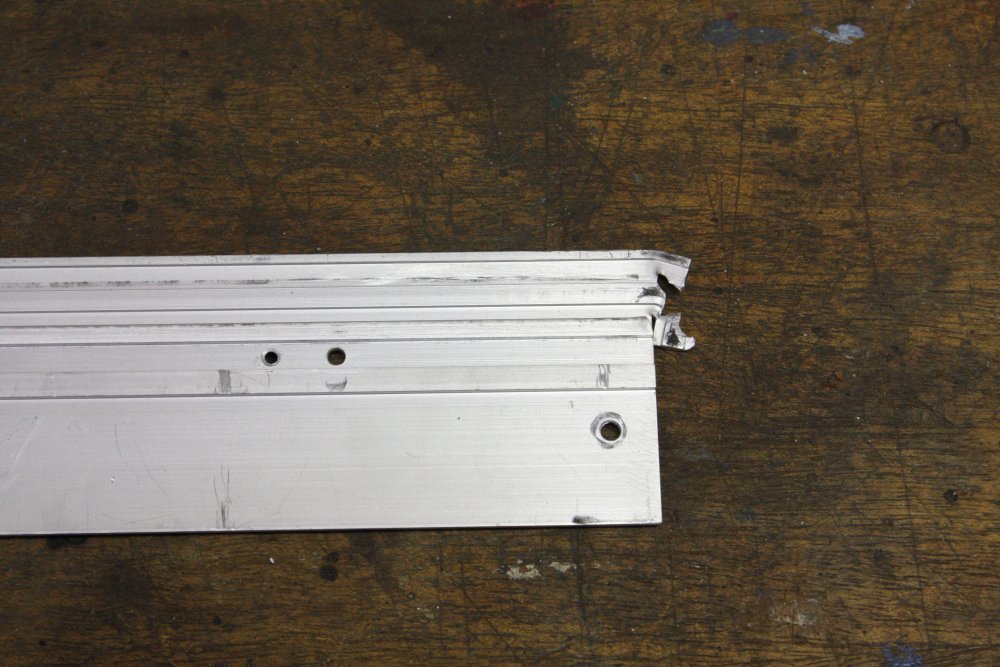
I fetched a couple of modules I knew (probably) work, and tried to plug them in. And so to the title of this section... Doh. Oh for crying out loud. Stupid me. When rebuilding those tabs, I had just assumed the left and right ends of the top and bottom plates would have tabs with the same dimensions. Because what idiot designer would make them different when there's no need for them to be?
I mean really... sheesh. They are different. The holes are about 1.5mm differently spaced from the end line of the plate. I (finally) checked on another rackmount 7000 series scope, and yes, it really is like that.
Result: the RH bracket is now 1.5mm closer in, which prevents the RH module from being inserted.
Sigh. For now just undo the top and bottom screws so the bracket can move out. Plug in the module. Dammit. I am going to have to re-blob and re-cut those tabs. But this time I'm not going to disassemble the scope, just use a lot of protective covers and masking tape. Feeling pretty stupid atm. That's probably the silliest and most painful wrong assumption I've fallen into for quite some time.
Crap. And other words.
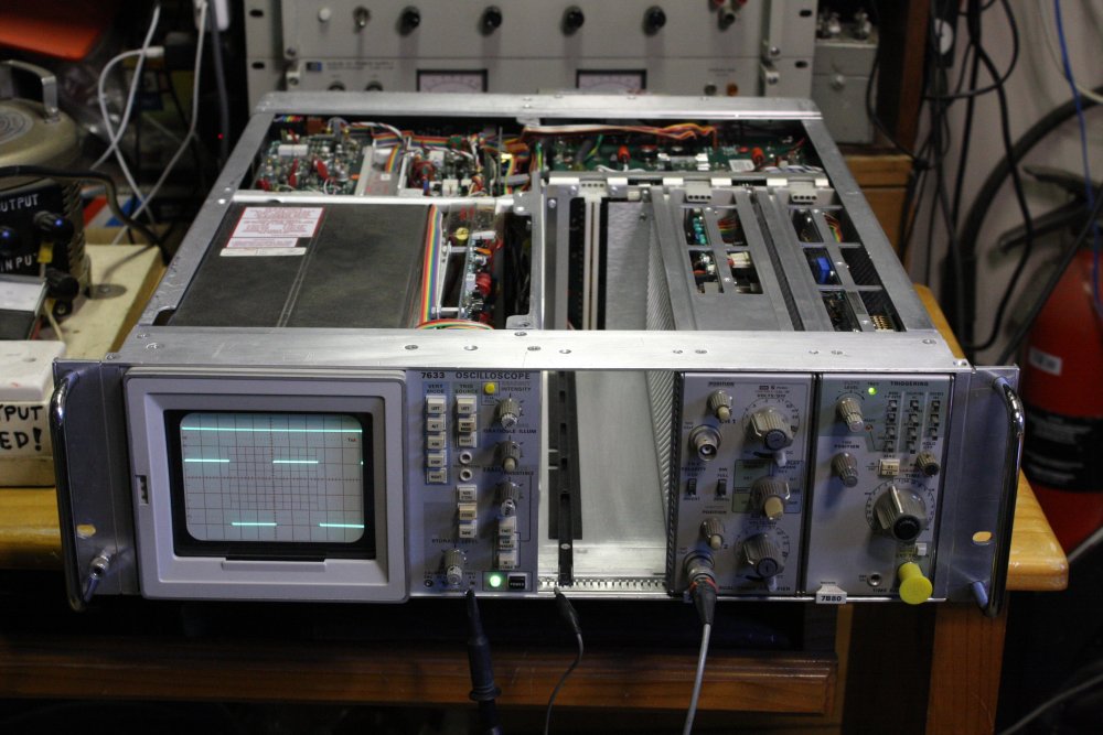
4. As consolation, the scope works, mostly. Clean trace in non-store mode. Storage works too, but I think it needs some fine tuning. Not surprising considering the complexity of the storage PCB and age of the CRT. One thing that is totally not working is the readout board. Nada from it, apart from some burn-in of the readouts in storage mode. Oh well, I was planning on digging into the readout board next anyway. But now it will be later... after I re-do those darned case tabs.
5. Most annoying misalignment of holes, ever? (For me at least. I usually transfer-drill hole pairs, so rarely see misaligned holes in stuff I do.)
20160514 Let's try that again
 |
 |
 |
 |
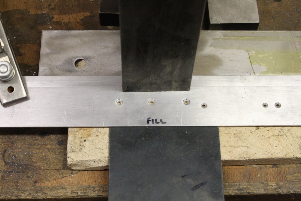
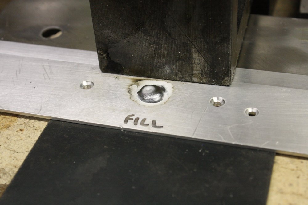
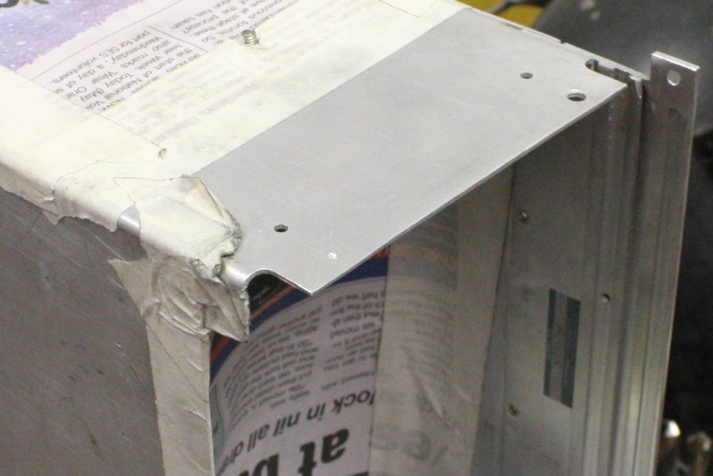
1 - 4. Fixing the top rail. And while I'm at it, filling in a hole that has no purpose. Why was it there? It seemed to be a mistake, and could that be anything to do with the "SN00001" thing?
Incidentally, in pic 3 you can see the surface cleaning effect of the arc. Aluminium is a highly reactive metal, and always has a solid oxide coating when exposed to air. When heated in air the oxide layer becomes very thick. Almost any oxide layer prevents two molten aluminium surfaces from wetting together.
In DC TIG welding (as used for steel), electrons move from the torch tungsten tip to the metal surface, heating it with their impact. But they aren't able to knock off surface oxidation. So DC arcs can't weld aluminium. The current has to be reversed for some percentage of a repeating cycle. When polarity is reversed, electrons are flying from the work surface to the torch tip (heating the tip much more than the other way), but due to the electron direction of flow and shield gas positive ion bombardment of the weld surface, the oxide film is broken apart and blown away. That's what the lighter, matt surface around the filler rod blob is — an area of metal where the arc has cleaned the surface. It stays oxide-free due to the inert (and expensive) Argon shielding gas, aka blowing money out a nozzle.
It's a trade-off; the greater percent positive duty cycle the more cleaning effect, but the less heat transfered to the weld, and the greater the wear on the tungsten torch tip.
Another effect visible is the frosted dimple on top of the blob. Aluminium has a high thermal expansion, and while cooling it contracts a lot. The dimple is where the surface pulls down into a depression as the last of the molten blob's internal volume cools and shrinks just at the point of solidification. It's frosted because it is being deformed while nearly solid, so the smooth surface of the originally molten blob is distorted. At this stage of the welding process there is no arc, but the welder nozzle is still enclosing the hot aluminium in shielding Argon, so there's little oxide film formation.
 |
 |
 |
 |
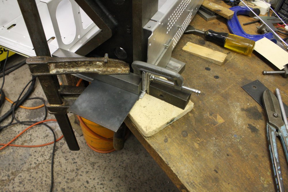
1 - 2. Preparing to redo the bottom rail tab. Masking to keep metal filings out of the electronics. Another worry was whether TIG welding to the scope frame could harm the electronics? The starter arc is high voltage, and the ground return cable's inductance means the scope case will receive brief HV-HF spikes. I decided to risk it. Though being sure to fix the ground clamp on the same bit of metal as I was welding, and as close to the weld as possible.
3 - 4. Another blob. There's no way to make them pretty, but at least with this one I only needed to weld on one side. I'd come up with a way to make tiny dams around a gap underneath by packing in furnace insulation. (Similar to fiberglass insulation matt, except much higher melting point.) It worked.
 |
 |
 |
 |
 |
1. Since I'm getting so much practice at this 'blobbing on thin aluminium' thing, I thought I'd also fix the bad hole on the scope side panel where a screw head had pulled through the thin sheet as the RH bracket was torn off. This aluminium is only 1.5mm thick, and the hole is close to the edge. Which together make this extra hard. Molten aluminium has a high surface tension, so a thin sheet edge going molten just wants to pull back into a ball. Same at the edge of the blob, where it merges with the sheet. It's a very fine line between 'bonding to', and 'melting away' the sheet.
2. It worked! (Much to my surprise.)
3. The repaired sheet, centerpunched ready to drill the new hole.
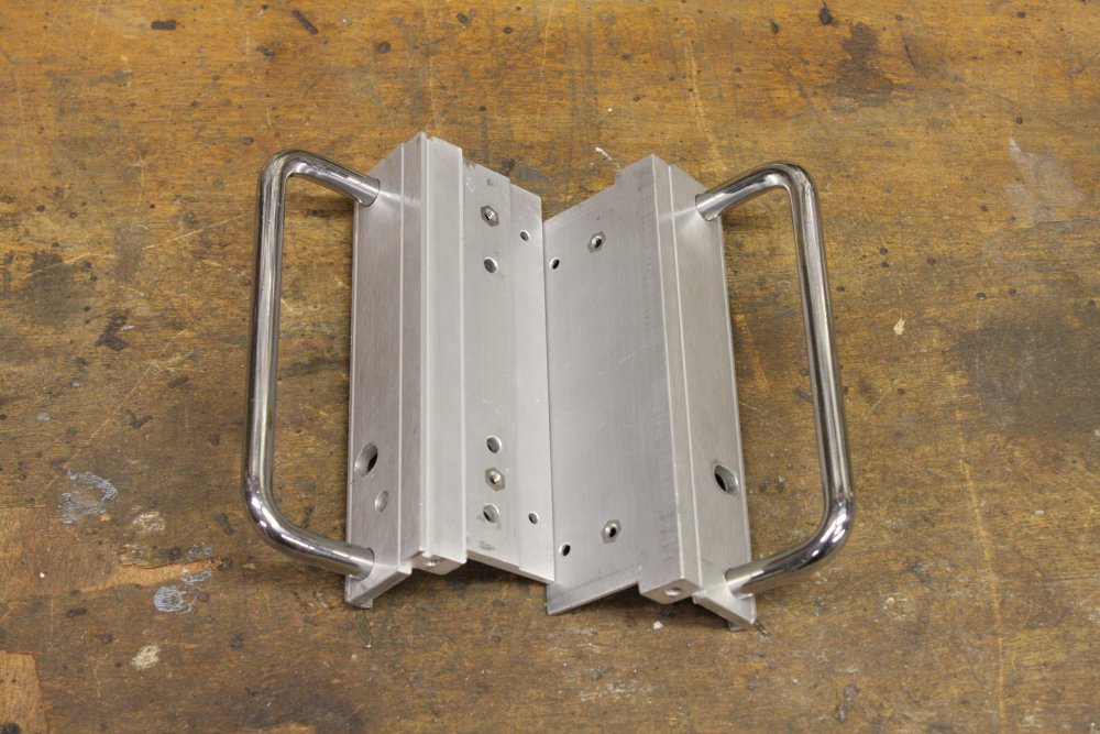
4. Fixing up the extrusion profile on the lower tab. Again.
5. So, the TIG welding didn't break any of the electronics. The scope works the same as before, except now the right-hand plugin fits properly.
Are we there yet?
What a lot of trouble just for curiosity! Back when I bought this scope I already had a few Tek R7903s (500 MHz and very nice scopes.) This R7633 is only 100 MHz, and storage tubes don't tend to last well so I didn't expect it to be a great scope. I really only wanted to have one example of a Tek storage tube scope, to learn about how they work. It didn't cost much relative to my income then, and the whole exercise would have been straightforward if the scope wasn't trashed in shipping.Some people may have just binned it, or used it for spare parts. But I see these things as historical artefacts, worth putting in some effort to preserve. Even if this was just any old Tek scope the effort so far would be justified. But it seems this one is a rather special unit after all.
To explain why, I'm first going to tell a short story from my professional life. It's about a circuit board remarkably similar in some ways to that odd Readout PCB with surface mount parts in the R7633 scope.
So no, we're still far from the end of this tale.
No ground plane, no work
Back in the early 1990s I was working for AWA Wagering as a software contractor. They do various betting systems hardware and software, for racetracks, the TAB, etc. Mostly I worked on 6809 assembler code for racetrack betting terminals. Mega-boring, but it paid well and was enabling us to dabble in realestate investments.Another project AWA Wagering had running at the time was being done by an outside contractor. It was developing a 68000-based board, to be used in kiosk betting machines called 'Mystery Bet'. The board had been designed and manufactured, but the software development stage bogged down. The programmers kept encountering bugs they couldn't diagnose. They wanted some hardware test routines, and asked me to do that. In the process I came to suspect the design wasn't stable. I had a logic analyzer with a 68000 emulator pod, so offered to bring that in. Management accepted.
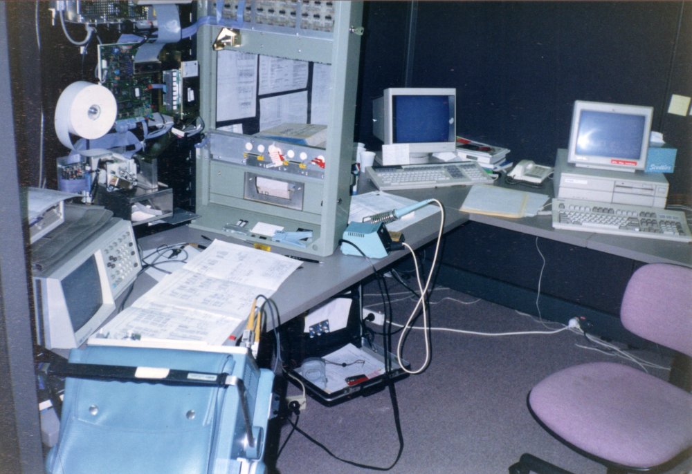
My desk at AWA in May 1993. (Scan from old photo.)
The logic analyzer's 68000 emulator pod is just out of view at top, with the fat ribbon cable to a socket on the large PCB in the open-cover Mystery Bet machine.
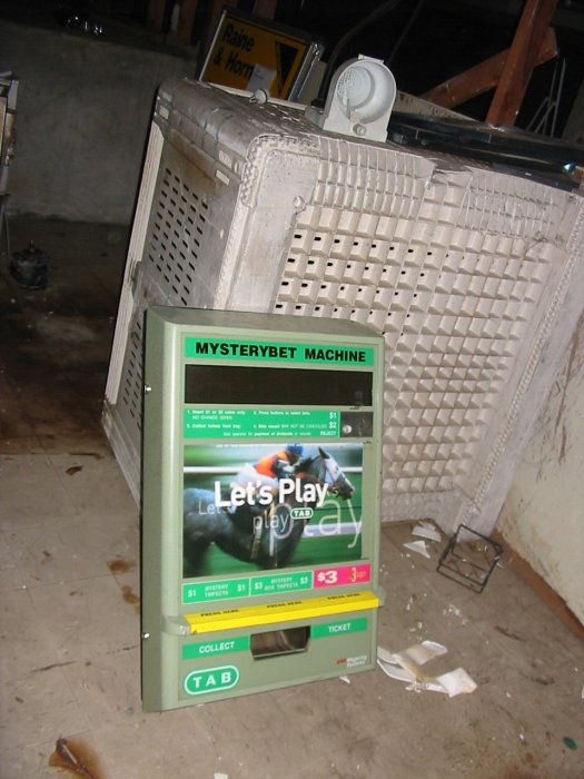
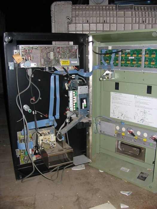
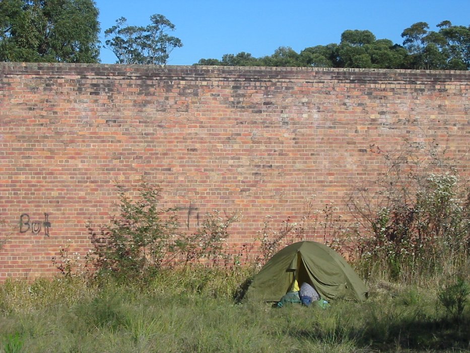
In my spare time I enjoy a little Urbex (Urban Exploration) now and then, with like-minded friends. In 2009 on a trip to Newcastle area (Nth of Sydney), I found one of those Mystery Bet machines in the basement of an abandoned clubhouse. And salvaged the main PCB out of it, because there's a story to it. I'm pretty sure I know why this machine was pulled out of service and stuck in the basement, dusty but apparently very little used.
 |
 |
 |
 |
 |
 |
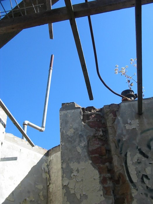 |
1 - 3. The machine in the basement.
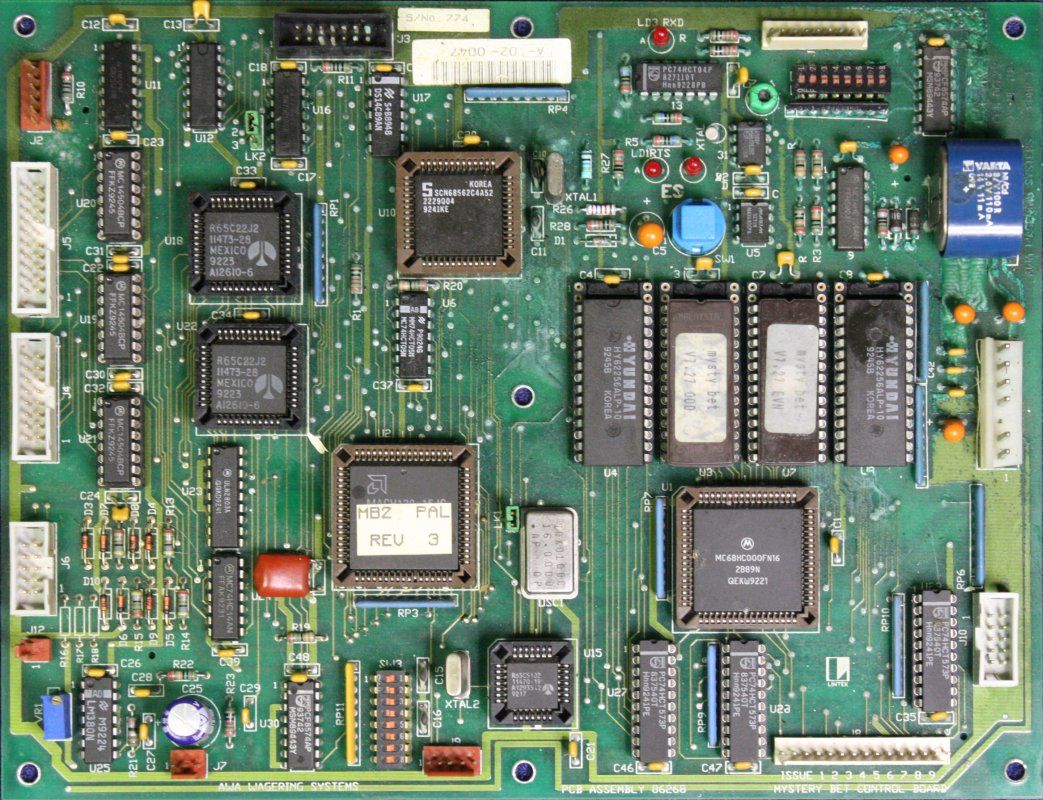
4, 5. the Mystery Bet circuit board.
6, 7. Other pics from that trip.
The reason wasn't the 'leaked NiCad battery' corrosion obvious in pic 4. That happened later, and I don't care. Because this board never really worked. It was nearly the most incompetent design I've ever seen, and it's up against some stiff competition. Even before I started on it with the logic analyzer I found a long list of design flaws.
Once I did weigh in with the analyzer, I found the board was experiencing intermittent logic failures due to ground bounce. When enough bits on the address and data buses flipped in the same direction at once, the current pulses via chip ground pins were shifting the local 'ground' level on PCB traces enough to cause other chips to sense incorrect logic levels. It was very marginal and difficult to repeat, but I did capture definite occurences. I can't find a writeup of that, but remember being extremely disgusted. Mainly that the contractor who designed this piece of junk was apparently getting a much higher hourly rate than mine.
From the moment I first saw this board I'd had a hunch it would have ground bounce problems. I could see it was laid out by someone with no conception of high frequency effects. It's double sided with no internal ground and power planes, not even much attempt to maximize ground conduction mesh. For the bus width and logic speeds on the board, there simply isn't a solid enough ground mesh. Fundamentally, the PCB as is was unworkable. (Quite apart from all the other dumb design mistakes.)
I wrote up a report, showed what was happening, recommended the board be redesigned by someone who knew what they were doing. Offered to do it myself if they wanted. Well within my level of experience from previous work.
But I don't think management were able to comprehend the technical points. They tried to proceed with the existing board, and in fact did (somehow) get the code to mostly work. Sold some of the Mystery Bet machines. I later heard they were a costly commercial failure, due to frequent faults and crashes. Just what I'd said would happen, and hence the abandoned machine in the basement.
Déjà vu of the PCB kind
 |
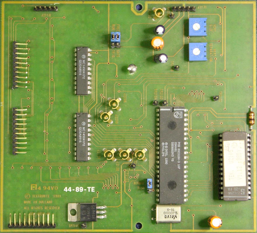 |
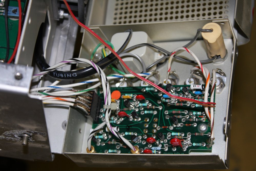
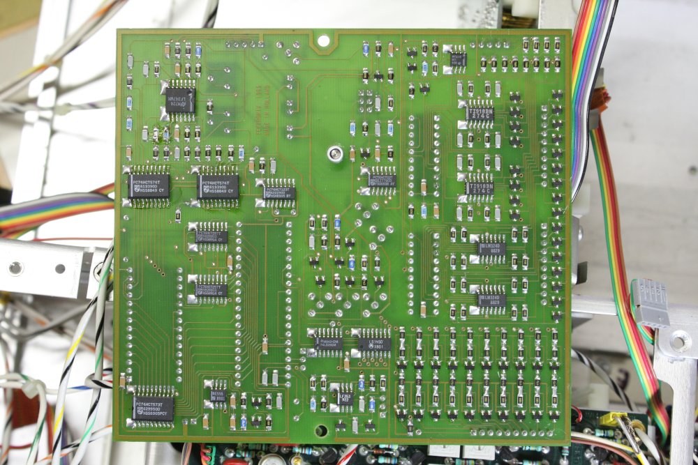
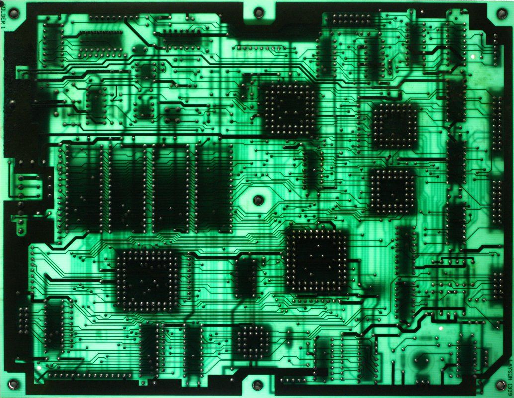
OK, so this readout board in my Tek R7633 scope only has an 80C31 CPU not a 68000. But it's still running at 12MHz, and the board's ground layout is incredibly bad.
There's that same HF-naive style, of running power and ground around the edge of the board with a few thin traces inwards to whatever nodes need them. As if these traces had no inductance, and formed a theoretically perfect 'all at one voltage' reference. It ain't so.
 This board is actually far worse than the Mystery Bet example of bad layout practice.
The most striking flaw is that the edge rails ring isn't even complete. On the bottom edge in the pics there is a gap at the center. Making the power rails a large 'C'.
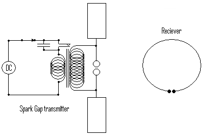
Which is fine if the intention was to repeat Heinrich Hertz's pioneering work from 1887 demonstrating radio waves, with a C-shaped simple spark receiver.
Presumably that wasn't the intention. Still, this board's layout is a fine effort at building a transmitter and receiver of radio waves.
Naturally, I'm curious to see how reliably this board works.
But first I'll need to sort out why it currently isn't working at all.
There were three versions of the Tektronix 7000 series readout generator board:
- Schematic "REV NOV 1985 1767-100" (SN B240053 and below for 7633.)
- Schematic "REV FEB 1989 1767-115" (SN B240054 and up for 7633.)
- This one. Thanks to PA2HK on the forum for this information: "that is the late model Tek7000 readout board. I have the same board in a late model Tek 7904A mainframe. Schematics are known and you can find them on Tekwiki w140.com at the end of this 7904A service manual:
http://w140.com/Tektronix_7904A_OCRed_by_Tabalabs.pdf
This board has been used in the last incarnations of the R7903, R7844, 7104 and 7904A mainframes build in and after 1990."
The addendum with the Ver 3 readout information is indeed right at the end, starting at PDF page 380. It's the final 11 pages of the Change Information section, and isn't mentioned in the manual Index. Unfortuntely, the PDF quality of the schematic is horrible. (So what else is new.)
To be continued...