A young electronics enthusiast I know lives in a SE Asian country where it's hard to find and afford basic test gear. It took me way too long to remember that I have an old analog 20MHz oscilloscope, that is dead but probably repairable. It was given to me years ago, broken, and back then I'd had a go at repairing it but didn't have a circuit diagram. I'd given up and shelved it, with me thinking eventually I'd repair it and give it to someone who needed a basic scope.
Much later I did find a schematic online, but didn't make another repair attempt. Then I'd forgotten about the scope till now. This is about fixing it, to give away.
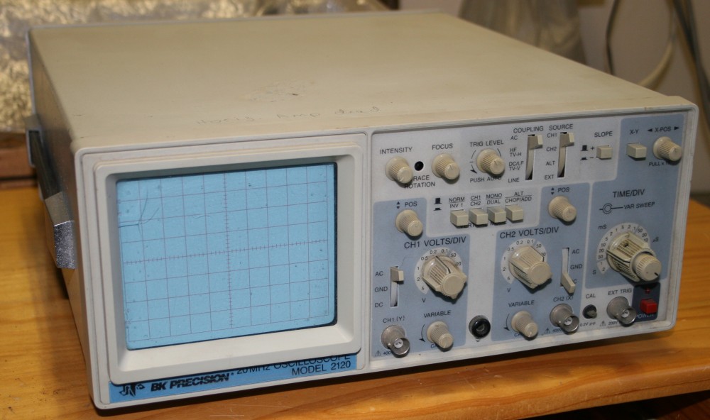
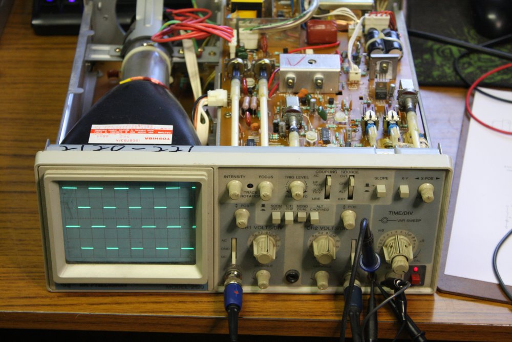
It's a very basic scope. A BK Precision model 2120, 20 MHz dual channel.
Silly me, I forgot to take a pic of the faulty display. Basically, just a dot near the center of the screen, with about one centimeter of 'sweep' to the right of the dot. Vertical position control works, Horizontal position control does almost nothing. I'd assumed the horizontal deflection amplifier was dead.
Also there's a crack in the thin clear perspex cover over the CRT. Easily replaced.
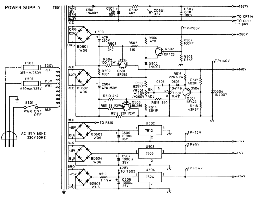
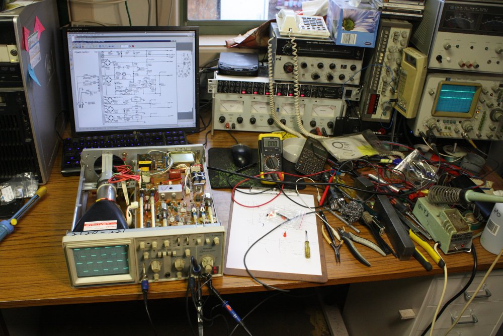
Here's the manual (900KB), and circuit diagrams (1.8MB).
Debugging goes so much better with a schematic! (If only there were schematics for life-problems.) It didn't take long checking test points with a multimeter to discover that the +260V power rail is dead. It's just 22.6V. And this turns out to be the supply to the horizontal amplifier.
Good, that's a simple circuit, this won't take a moment. Ha ha ha... Nope.
I'd expected a bit of poking around with the meter would immediately identify the problem, and also expected it would be a bad Q501 or Q502. The way this works is it uses the +140V rail as both a bootstrap, and a voltage reference. The negative end of the main electro C503 is pulled up towards the +140V rail by Q501, also raising the positive end of C503 until the base of Q502 matches the +140V rail. With the divider of R507 & R508, that sets the output at +260V.
Or, it would if it was working.
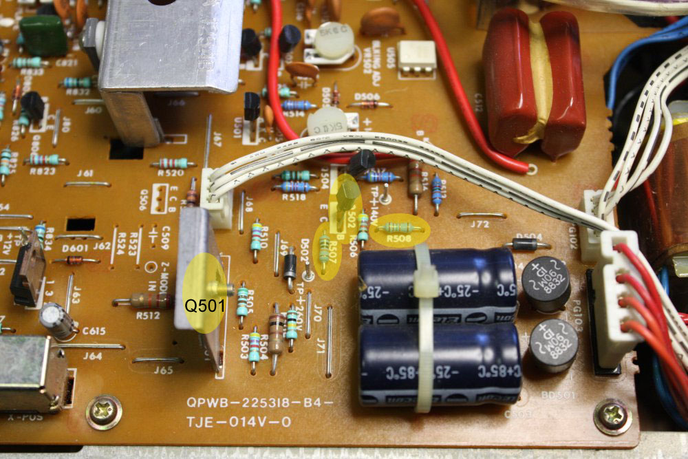
These guys. Checking, yep, Q501 is not turning on at all. Because Q502 is not turned on at all either. And that was when it got weird.
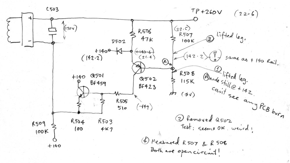
Q502's emitter is at almost the same as the 22.6V output rail. So there's no emitter current. The Collector is at -149V, which is also to be expected, given most of the 170V across C503 is floating negative.
Right, so Q502 is probably failed open. Just check the Base... what? It's +142.2V. But, but... That's exactly the same as the "+140V" rail. There's no possible way that's getting there via R507/R508. So there must be a board short on the solder side of the PCB.
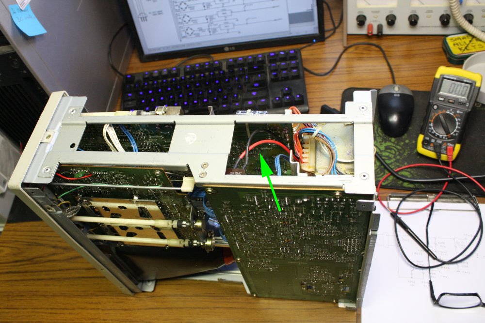
The board area is there, at the arrow. Awkward but possible to access, thank goodness.
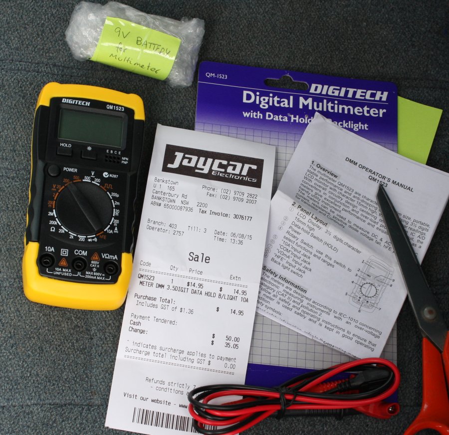
Yes, I am using an extremely cheap multimeter here. Just happened to be the first one to hand.
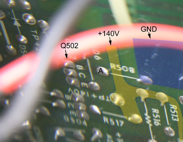 Sure enough, there is a very close track spacing between the +140V trace and copper of node A.
But it looks OK. Can't see any sign of board carbonizing. No solder whisker, no dirt... Measuring it with the meter on ohms (scope powered off) says there is nothing. Can't detect any conductance at all. Yet with the scope on, there's +142.2V on node A.
Hmmm... Maybe it's tracked through the PCB, to the metal end cap on R508? Seems far fetched, but to eliminate that I lifted out the node A leg of R508. And there's still +142.2V on node A.
At this point I gave that suspect gap between the node A pad and the +140V rail a good hard scrubbing with a stiff brush. After which there's still +142.2 on node A.
Well then, it must be.... f*ck, I have no idea. So lacking any idea I pulled out Q502, which I'd assumed must be vaporized, given the 120V of reverse Vbe bias present. Not to mention the 290V Vce.
More astonishment. It measures OK. Perfectly good. Whaaaat?
Flailing, I lifted the node A leg of R507. Bear in mind that all these desoldering operations are like keyhole surgery, given I have very small paths of soldering iron and sucker access. Oh and those wires in the way? Those are the mains switch wires, so burning holes in the sheath is not acceptable.
I'd meant to see if there was still +142.2V on this node despite having absolutely nothing connected to it, but then realized for the same reason I can't probe it from the top of the PCB. Duh. And then I just happened to measure the resistance of R507 and R508, since they are now both sitting there with one leg in the air.
Wait, what? Both these resistors can't be completely open circuit, surely? Oh great, now the multimeter ohms range is broken? I grabbed another 100K resistor from the scraps bin. It measures 100K.
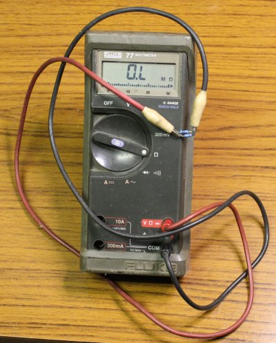 Good grief, both R507 and R508 are actually completely open. See at left, the two of them measured in parallel, showing open. These are both quality 5-band 1% tollerance metal film resistors. Were.
Finally, my dim wits start to grasp what's going on here. There's a nube design mistake in this circuit. These little 1/4W metal film resistors don't like high voltages. It's not a matter of heat dissipation, it's that the thin metalization spirals on their ceramic body are notorious for going open circuit over time when there's a largish voltage across the resistor.
But how did they both fail? One should have gone first, leaving the other intact?
Oh but wait... they were both open, but there was still +142.2V on node A.
Ah! but given they are both open, that means node A is effectively floating, so long as Q502's base junctions are reverse biased. Which they are...
So even a very slight amount of surface leakage across that narrow gap from the +140V trace, to node A, will be enough to float it up to the same as the rail. Bad, bad, design!
I'd guess R508 went open first, resulting in node A falling to near ground. That stressed the PCB gap from the +140V rail to node A, making it go leaky and pulling node A up to just below the +140V rail. But the +260V rail stayed down, so now R507 still has more than 100V across it. And it failed too.
 So, fix it already!
The original ratio was 100K : 115K = 0.8696
Replacing with pairs and tripples:
47K + 47K : 56K + 47K + 4K7 = 0.8727
(A 5K6 would have been better at the last place, to give 0.8656 but I was too lazy to go get one.)
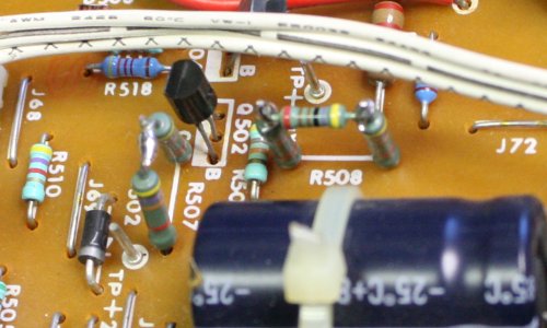
The new resistors in residence. That gap between tracks got a good scraping. And the original Q502 is back in.
Now it works. Everything seems good.
As for shipping, fortunately there is a shipping agent in Sydney that exists specifically to do this exact thing; used by Philippinos in Sydney to send stuff to their relatives back home.
 |
 |
 |
 |
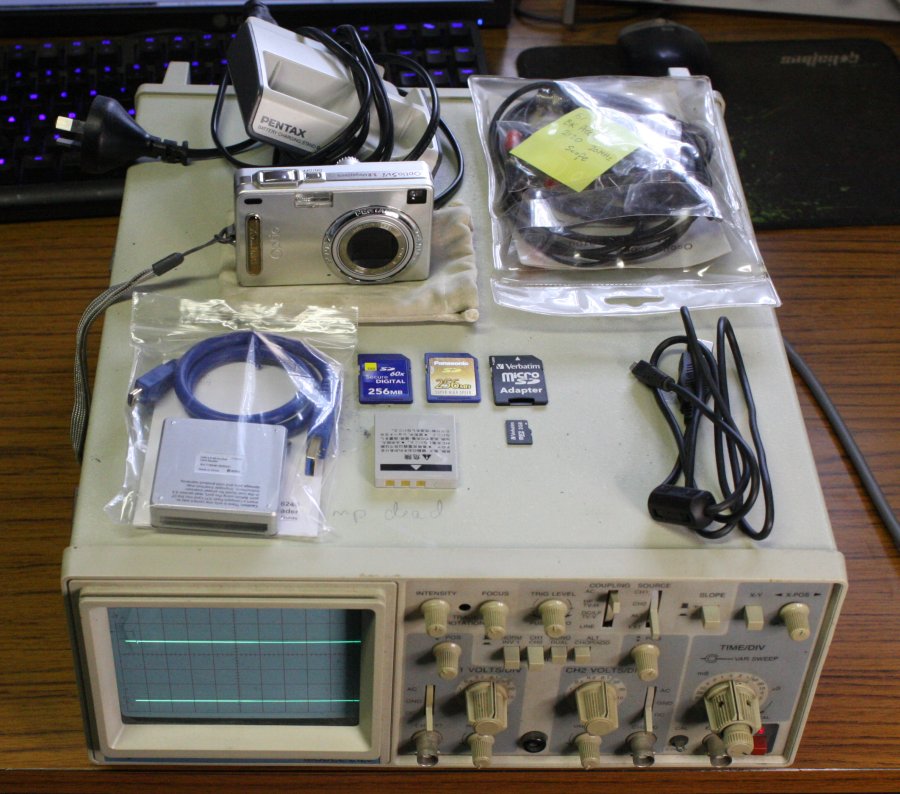
1, 2. It would be silly to send a box with just the 'scope in it, so I added a few more items.
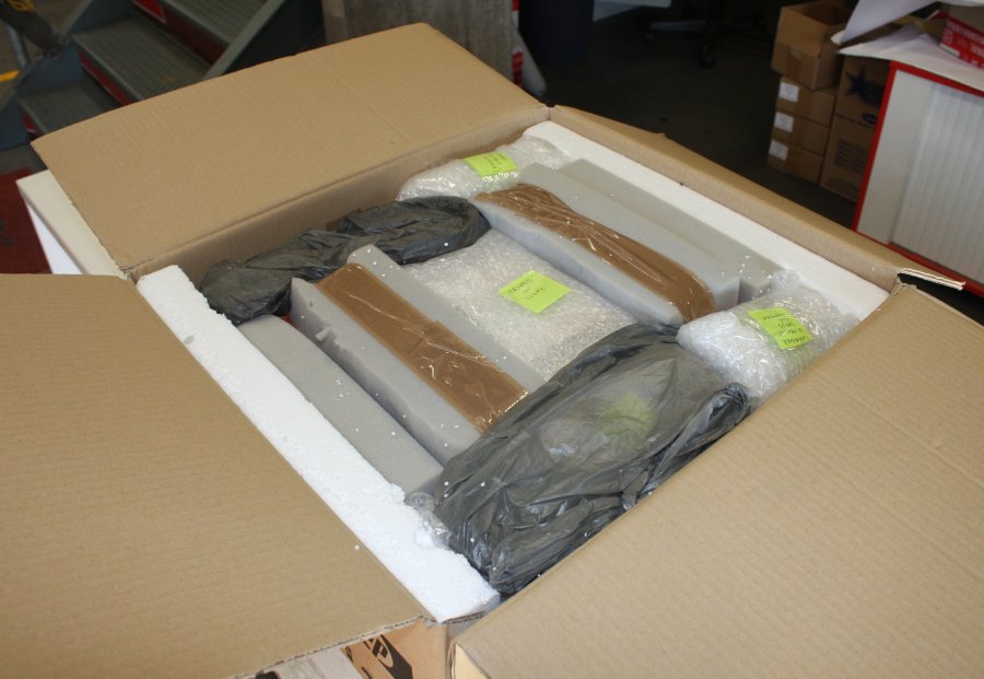
3. The packed box. The 'scope is the thing with foam padding blocks all around, secured with packing tape. Then I added the other stuff in the cavities. Which somewhat depleted the utility of the foam padding blocks, but oh well.
4. The shipping company. They were very helpful and reasonably priced.
 |
 |
My friend's workshop in Bohol, where it ended up. Yes, it survived the shipping.