Back in Nov 2011 a thread on eevblog reviewed an old Tektronix instrument from 1969, the model 2901 Time-Mark Generator. I hadn't heard of this before, but reading about its functions, and seeing the photos of the beautifully made old-style circuit boards, I wanted one for my collection.
 It took a while to find one on ebay at a price/condition I liked. Finally in Dec 2014, success!
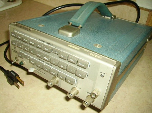
Seller's pic at left.
Price US $56.12, plus $12 postage to my US reshipper. There I had it consolidated it with some larger, heavier items for shipment to Australia. As usual Shipito and TNT did a brilliant job, taking just four days to pack the items together, then transport the box from Los Angeles to my house in Sydney Australia.
The seller's ebay description:
After unpacking, the first thing is to switch the mains voltage selector to 240V. It's easy to forget that voltage switch, so I always make sure to do it before cutting off the US plug and replacing it with an Australian type. This time with extra thanks to Tektronix, since one of the other items in that shipping box was a power supply for a Zeiss microscope mercury arc illuminator lamp, which had turned out to be 110V only. Not even a winding on the transformer for 220V.
Once sure I couldn't forgetfully blow it up, curiosity demanded the covers came off immediately. Ahh! Two immediate nice things: firstly it's intact, nothing missing or damaged. Secondly, perhaps surprising to some, is the smell. As with old books, old electronics instruments have a range of smells. Some of them tell you about faults, for instance the distinctive stink of failed polyester mains filter caps. Others are just nice; a kind of 'warm circuits' scent that I like. This one has it.
It's also dirty on the outside, so this was a good time to clean the case. The handle and feet get removed from the covers and all the pieces dealt with — scrubbing and brushing. Overall it's in remarkably good shape for something 45 years old, but there's dust, grime and corrosion, that it looks a lot better without.
The worst visible signs of age are both chrome plating failures. The body frame is made of diecast alloy, on which there are a few spots where the diecast is corroding under the chrome, as typically happens. The carry handle end clips are chrome plated steel, with the chrome applied directly to the steel rather than with copper plating between. And so the chrome is peeling off in a few spots, as it always does without the copper.
The case has no air vents to let in dust, so inside it's pristine.
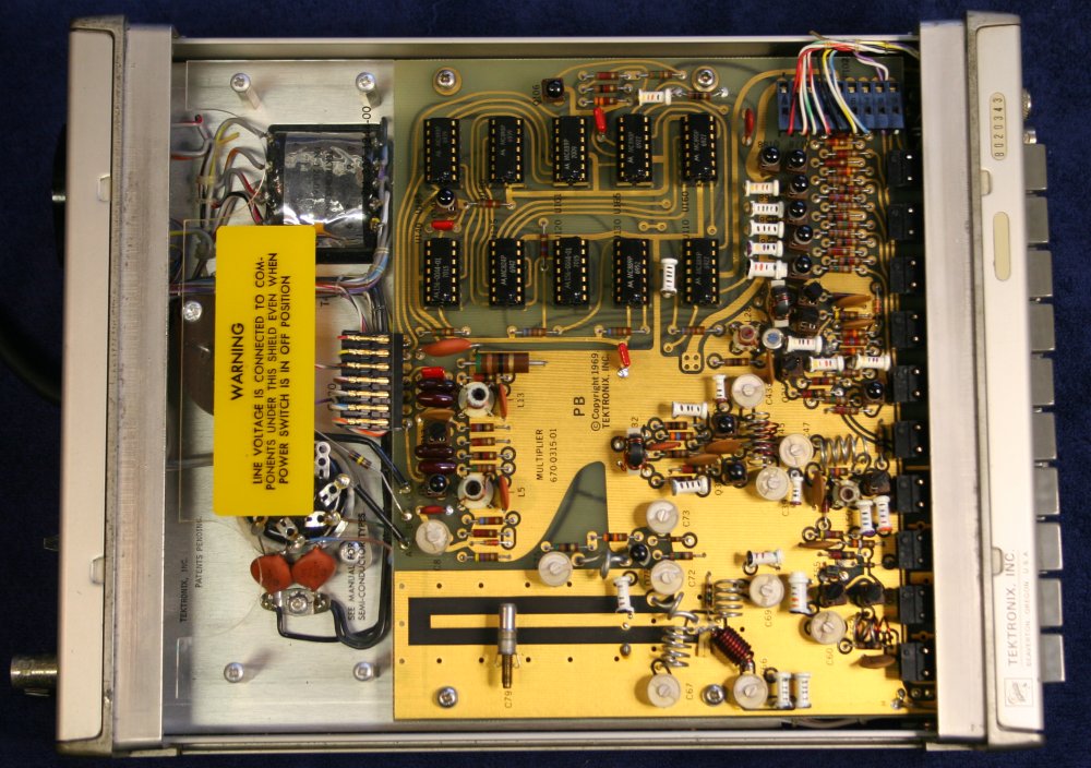
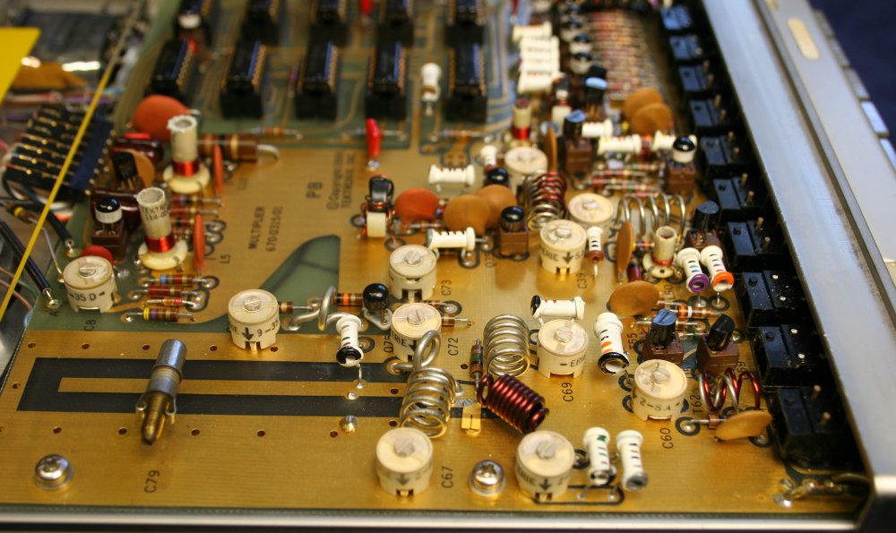
Ha ha. Seeing this part of the circuitry in the eevblog thread was the deciding factor in wanting one myself.
This is beautiful! Both visually, and in what is going on electronically here. Even better, unlike a lot of contemporary high frequency electronics in which the components are so tiny you can barely see, and there's zero chance of finding anything like a service manual theory of operation, this design from 1969 is a comfortable size and there's a complete schematic and explanation of how it works. In the user manual which came with every instrument.
It's not just the instrument that is a relic from olden times, it's the entire engineering philosophy underlying this device that's reminiscent of a golden age, now gone. (Yes, yes, I know, modern stuff generally doesn't have dozens of manual tweek adjustments. Some things do improve.)
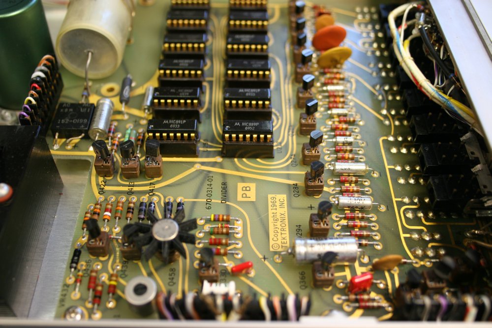
These printed circuit boards were designed using sticky black tape, that was unrolled and laid down on a clear sheet of plastic film by hand. The tape is flexible and so can be laid down in curves like that. My very first job involved laying out a lot of boards exactly this way, so these ones feel like old friends.
Heh. Though none of my boards from those days were ever gold plated.
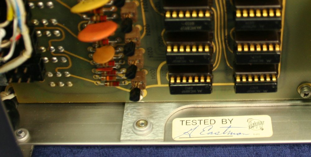
I wonder why the tested by tag doesn't include a date? On Tektronix gear they never do, so it must have been a management decision. I don't understand the reasoning there, unless it was felt customers might complain if they bought a unit that they found out had been sitting in stock for a while.
Anyway, the date codes on the ICs range from 6927 (1969, 27th week) to 7015 (1970, 15th week) which says the unit was probably made early in 1970.
Also what is Mr A (or M?) Eastman doing these days, if he's still alive?
Which brings us to testing. Does it still work?
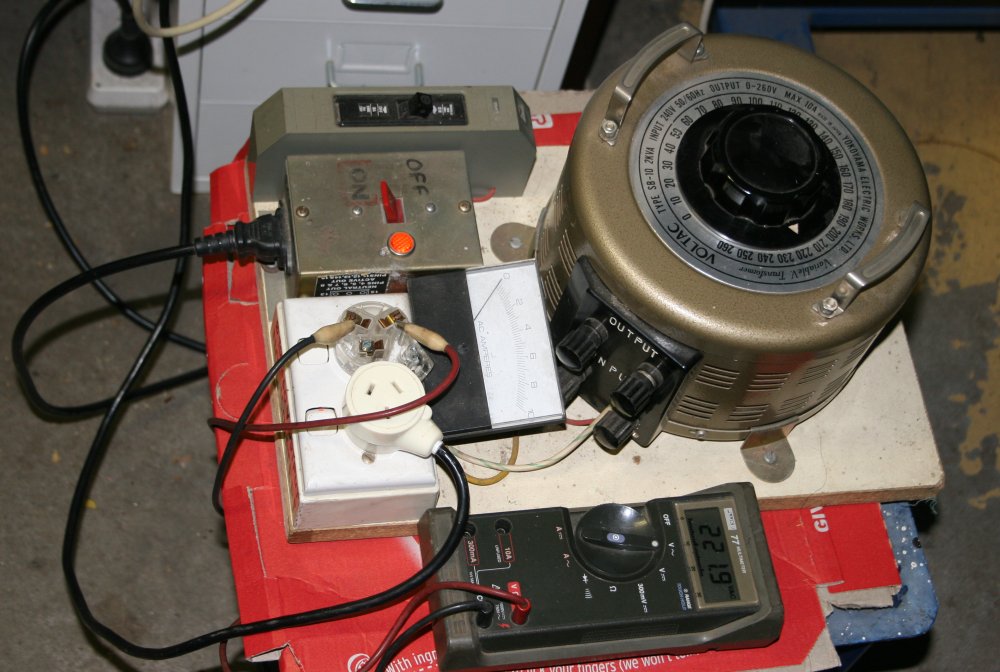
When powering up old gear for the first time, this is a must. A variac, with an output current meter. Turn the output down to zero, connect the device to test, start turning up the voltage slowly. If the current rises suddenly at some low voltage, something's wrong. This way you find out before letting any more of the magic smoke escape.
With the 2901 there was none of that kind of drama. Power light working and crystal oven light going on and off correctly.
Though I must say, the idea of using on/off heater control on a crystal oven seems very primitive these days. It means the temperature will be ramping up and down, rather than sitting at a desired value as you'd get from using a proportional temperature controller.
But then, I refuse to get sucked into the volt and frequency standards precision obsession. I guess it was good enough for 1970.
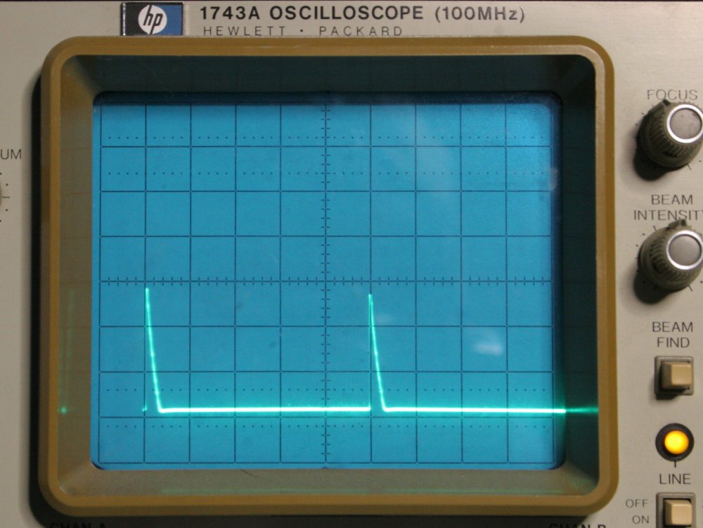
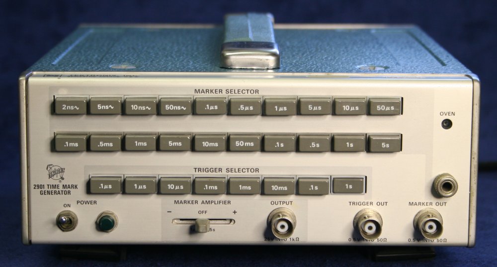
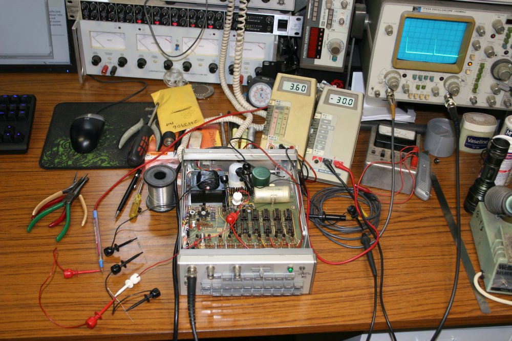
First thing I tried... works! The 5μSec interval marker. The old scope on this workbench is only 100MHz bandwidth, so the highest frequency (500MHz 2nS period) output of the 2901 is invisible, and the 200MHz is barely visible, but all the other markers along the top button row are working... Except the last one, 50μSec. That one and all the longer period ones are dead.
OK, faulty divider circuit between 10μS and 50μS. No problem, because I have the service manual.

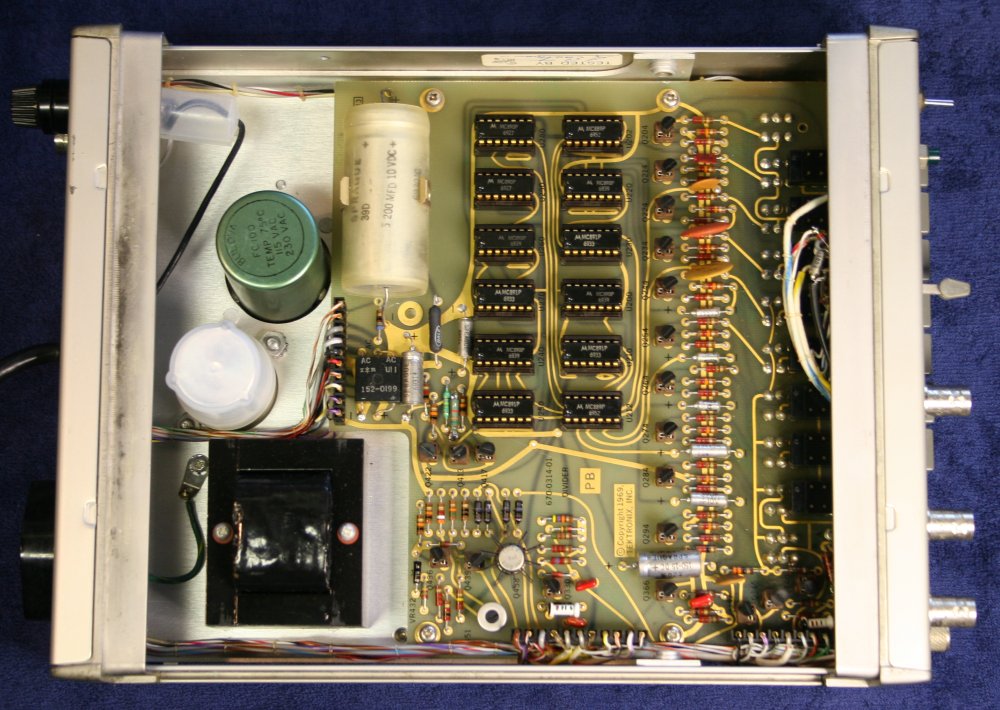
Sure enough, U165B is toggling, but U180 & U185A are doing nothing. But wait... What's this "3.6V"? Which also is the supply to all this logic. Huh... oh of course, thus stuff isn't TTL logic, which runs on 5V. With part numbers like MC890P, it's RTL — Resistor-Transistor Logic.
Cool! Despite my fondness for fairly old electronics, I don't recall ever working with RTL logic before. All the years I worked as a service technician, everything I touched was quite new (at that time, say 1975 to mid 80s.) So it was all TTL, LS-TTL, etc. Then in the last decade and a half as I've had access to 2nd hand test gear via ebay, stuff I've bought has been from the 1980s onwards.
So! Hello RTL. Do I even have any data books with these parts?
Turns out the answer is no, I don't. My collected library timeline began somewhat after that era. But google does have them. Sort of, as fragments of old data books. None of them complete with RTL family specs, such as the supply rail operating limits. I add the 'Motorola Microelectronics Data Book, 1969 Second Edition' to my shopping list.
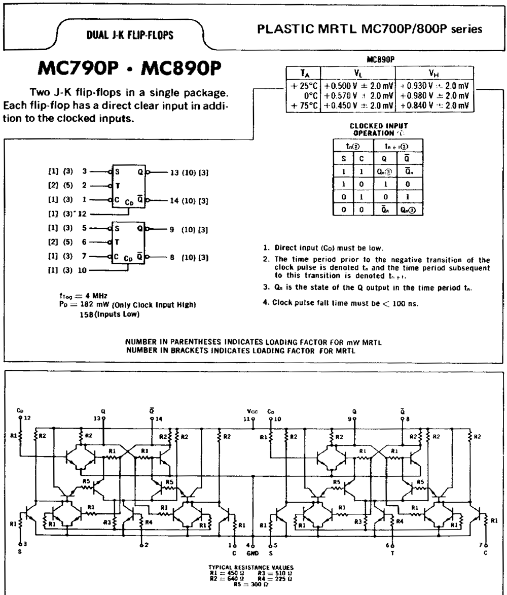
Fragments like these... An example of RTL logic chips.
When debugging old, socketed parts, best to first give the ICs a wiggle in their sockets. Lift them up a little, push back in. This generally fixes, or at least changes bad contacts. Here, it has no effect. I briefly started looking at pins with a scope, but had by now noticed another problem that took priority. I'd been trying to find the RTL family specs, because although the manual says "3.6V" for that supply rail, in this instrument it's only 3.45V. This doesn't sound right. Is something in the dead divide-by-5 circuit loading it?
Nothing felt hot to touch, but I pull the suspect chips from their sockets anyway. No change in the 3.45V. Just for the hell of it I swap those two JK flip flops (U180 & U185) with another pair of MC890P on the other board; U280 & U290, at the end of the low frequency divider chain.
Ah ha. Now everything works. Yes, the entire divider chain. Seems whatever's wrong with one of those flip flops kills the 10μS to 50μS divider but is OK in the different circuit of the 1 Sec to 5 Sec divider. Well, figuring out which chip it is, and finding a replacement can wait. For now, why is the power rail low?

The power supply circuit.
Hmm, there's no adjustment for the 3.6V rail. There is an adjustment for the -30V rail, and that acts as a reference for the 3.6V rail. But the -30V rail is actually about -32V. Correcting it to -30V makes the logic power rail even lower.
The 3.6V regulator is really simple. Just a differential pair driving a PNP darlington, all running off a positive rail from the transformer via a bridge and big electro C411. The unfiltered supply rail is fine at 8.3V, and about 800mVpp ripple. My first thought was that one or other of the comparator transistors might be flakey. I was quite surprised to see they are 2n3904. I've been using that part number as long as I can remember, but I didn't know it was that old. Anyway I have a bag of them, so pulled these ones. On testing in my ancient transistor tester, they have gains of 100 and 150. The specs are:
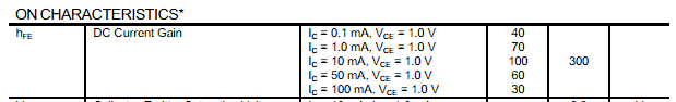
So they are in tollerance, though new ones all measure up around 300. I put new ones in anyway, for no particular reason. It didn't make any difference.
Noting voltages in circuit gives this:
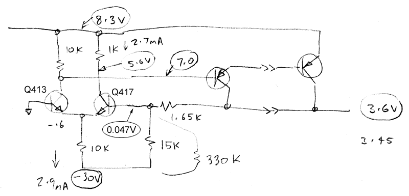
The base of Q417 ideally should be at zero, but is higher because the two transistors are very unevenly loaded. Of the 2.9mA tail current, 2.7mA is going through Q417. But that's correct for the design values. The circuit is working, but 'off'. Hmm.
It's as though the divider resistors R421 and R419 ratio is wrong. Working it, the stated values seem about right for what I'm seeing. Maybe the 3.6V rail was always low? Checking the manual, the test proceedure says this rail should be 3.6V +-5%. That's 3.42 to 3.78V. So actually it's just in range. But it is supposed to be 3.6V.
At this point I'd have liked to actually measure R421 and R419. I have suspicions...
That requires lifting at least one end of the resistors, however the component leads are bent over on the back, apparently. It looks like the board would be some trouble to get out to access the back. Awkward.
A quicker way (ha ha) would be to add a fudge resistor on the top of the board. To raise the 3.45V around 0.15V, requires a 330K resistor in parallel with the 15K R419.
Which worked perfectly using clip leads. (330K + 33K fudge resistor in practice.) So I soldered those piggy-backed on top of R419.
Annnnd... The 3.6V rail is now 3.4V! What?
Oh, I get it. R419 is a carbon composition resistor, and it's gone flakey. Soldering to its leads made it drift even more off value. Sigh. I removed the fudge, and fortunately found I could solder suck the PCB holes on R419's legs from the component side of the board. A little wiggling and it was free, without damaging the pads. (Old PCBs like this tend to be particularly fragile.)
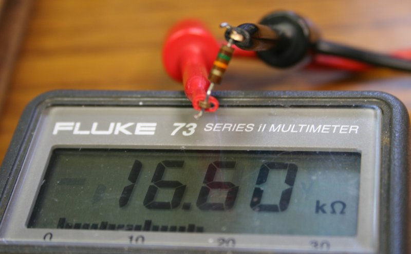
Measuring it, sure enough, it's not 15K ohms. Replacing it with a real 15K resistor produces a logic rail of 3.64V, which is fine.
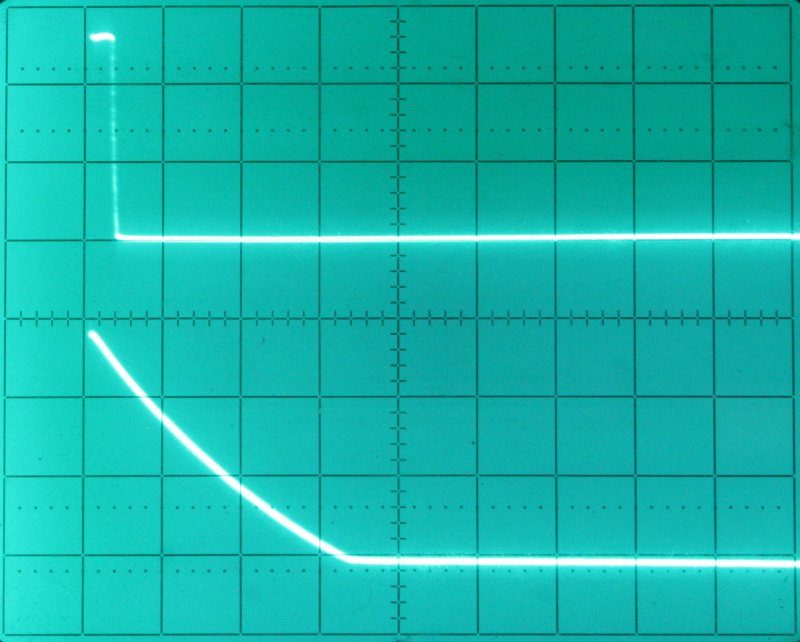
After that it was a relief to find the Trigger Output and Marker Amp outputs working right. Top trace is the Amp's +25V pulse, 10V/Div.
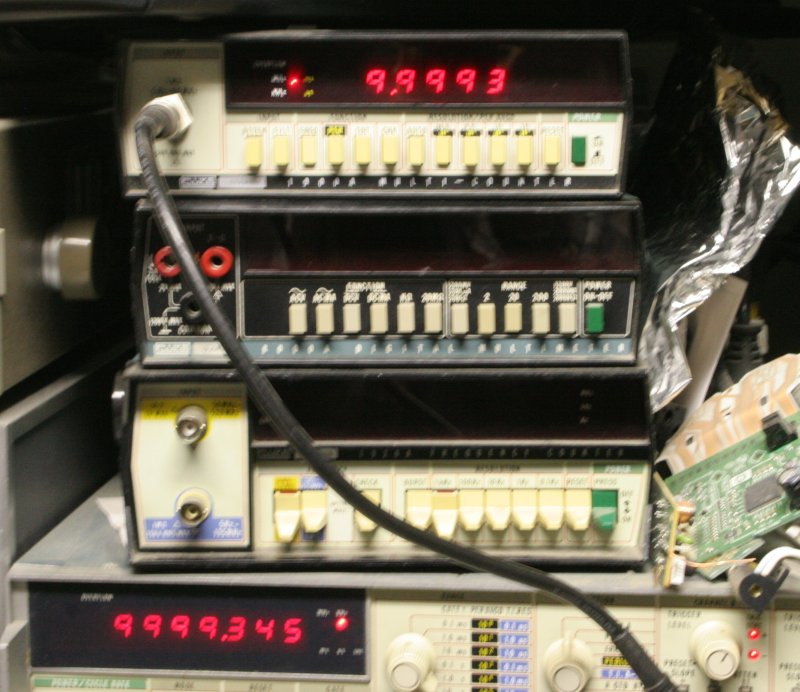
For those who care about accuracy, here's the 0.1μS (10MHz) frequency output. And just because these two counters agree, doesn't mean they are right.
I'm still not sure if the 500MHz output is working. Nothing on this bench has that bandwidth. Does the most interesting part of the PCB, with the coils and stripline resonator do what it's supposed to?
That will be something for another day.