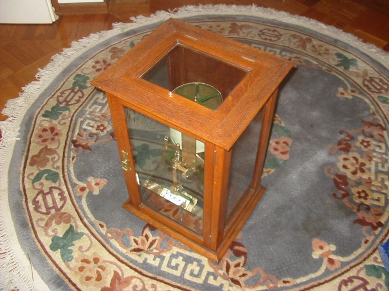
This is one of my best. It's a mechanical integrator, that was used to accumulate the total amount of steam that had passed through an electrical generator's steam turbine.
Since I'm interested in the history of technology, I like to collect examples. Unfortunately my resources are quite limited, and so my collection is very modest. I also don't have any facility to make my stuff publicly viewable. But here's a few samples.
This is one of my best. It's a mechanical integrator, that was used to accumulate the total amount of steam that had passed through an electrical generator's steam turbine.
This unit was found in pieces, scattered about the floor of a room in an abandoned and soon to be demolished coal fired power station, many years ago. The wooden casing was intact aparf from a missing latch, but was nearly entirely covered in pidgeon poop, and the original shellac was black and crazed. The interior mechanical pieces were mostly disassembled, and lying about among all sorts of other trash in the room. They too were covered in pidgeon poop, and horribly tarnished. I spent a long time there, rummaging in the mess, trying to be sure I'd found all the parts.
I'd seen where this was supposed to be mounted, on a venturi of a pipe leading to the turbines. There were four generator units, but all four measurement instruments were missing. Only later in a 'junk room' I recognised the remains of one.
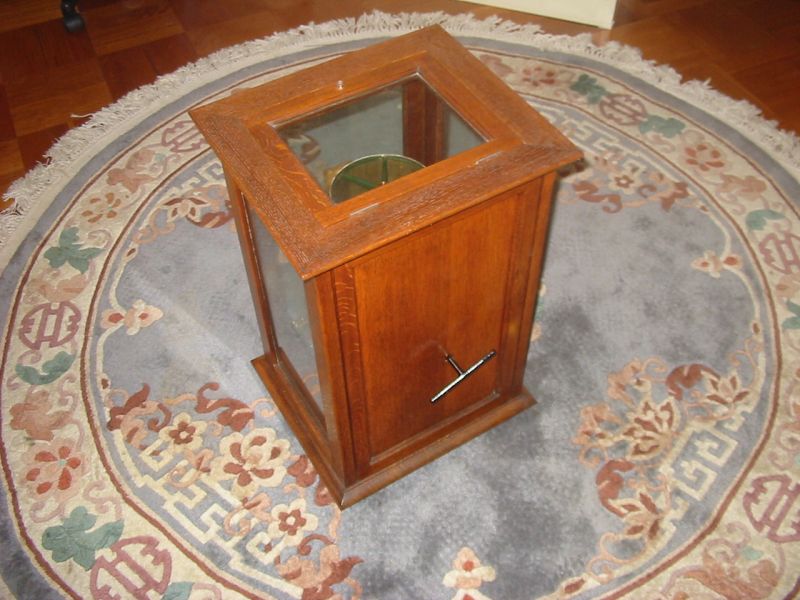
From the back, showing the winding key (which I made, no original was found.) The case took a lot of work, removing the old shellac, then re shellacing it. Originally it had been a smooth surface, but I resorted to a wire brush during the cleaning process, which brought the grain out nicely. I felt myself very lucky that all the glass panes were intact - it's almost unbelievable, considering the trashed state of the area where it was recovered.
When fully wound up, the clockwork runs for almost a week on a single winding.

The vertical cylinder with the graph paper rotates one revolution per day. I never found a pen unit, but it's clear there's supposed to be one on the end of that small 'L' bar. (I did find some glass fragments that suggested the 'pen' was something made of glass.) The result would be a graph of steam flow rate through the turbine. The red pointer shows the instantaneous rate.
The large black disk also rotates slowly, and that's where the integration happens.
At the bottom of the case you see a wooden base, but in its original setting there was no base. The instrument was bolted to the pipe venturi, and the wooden case fitted over the top and rested on a separate support frame. It could be entirely removed.
The vertical shaft you see, fitted into a plunger that rose vertically in proportion to the steam flow rate. Here it just rests on the wooden base.
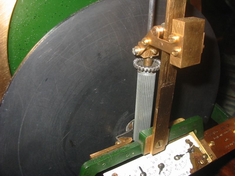
Closeup of the integrator. The gray shaft's vertical position is proportional to the steam flow rate. The ring of little steel disks is pressed against the slowly rotating black disk by the brass lever and weight, which has a roller where it presses against the back of the vertical slide. The little steel disks are wheels, which can rotate vertically so there's little vertical friction against the black disk. But they are sharp enough to resist sideways slipage on the black disk, so as the black disk rotates, the gray shaft rotates - at the same rate as the point of contact on the black disk.
Below that, the gray shaft is a long straight-toothed gear. This engages with the first gear in the readout accumulator gear chain, behind the dials below. And so, what this is doing is accumulting the moment-to-moment rate of flow. Effectively a mechanical implementation of area under the curve integration.
It's a shame the white enamel is missing from part of the dials bezel.
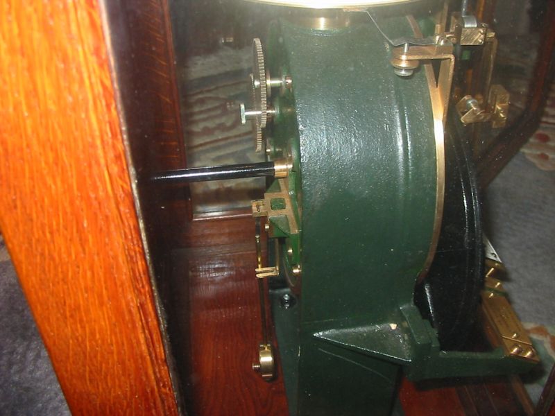
A view of the back of the clockwork body. Oops - while lifting this down from the shelf for the photos, I'd tilted it enough to dislodge the pendulum from the escarpment. No harm done.
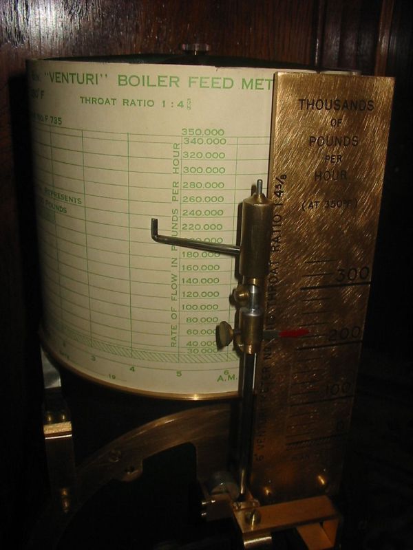
Closeup of the chart paper. I only found one.
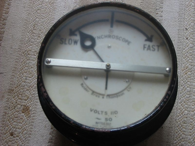
Something else rescued from a soon-to-be-demolished power station. A synchroscope.
When a power station generator is starting up, it must do so with the generator disconnected from the grid, since the frequencies will be different. Once the generator is at the right frequency, its output also has to be matched in phase to the supply grid before the connecting circuit breakers are closed. Otherwise there would be huge imbalance currents that could destroy the generator.
This is the meter that displays the phase difference. There are two AC inputs. One is the external electricity grid, the 'reference'. The other is the generator output. The needle can rotate continuously, around and around, which it does while the frequencies are not quite matched. When the frequencies are equal the needle stops. But the generator must then be jogged till the needle is stopped, exactly on that vertical black line at the top. Only then can the generator be connected. Otherwise bad things happen.
The meter face is a little blurry because there's some kind of frosty deposition on the inside of the glass. Perhaps some kind of oil evaporated from the coils. I'd rather not open the meter for cleaning, in case I break something. Note that it's 110 Volts - as was most of the control gear in the power station despite being on a 240V/415V grid system. I presume due to the predominance of US industrial equipment in those days.
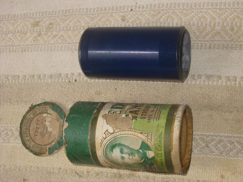
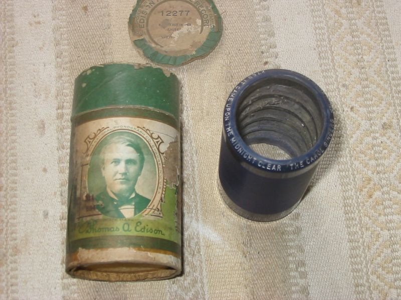
An Edison phonograph cylinder. I am not entirely sure the cylinder is an original, as opposed to a reproduction for use as a movie prop. This was another salvage from a building in the process of demolition. It had fallen down the back of some shelves, in a room otherwise empty. The room had once been used to store film production props. Hence my uncertainty of it's vintage. I like to think it's an original.
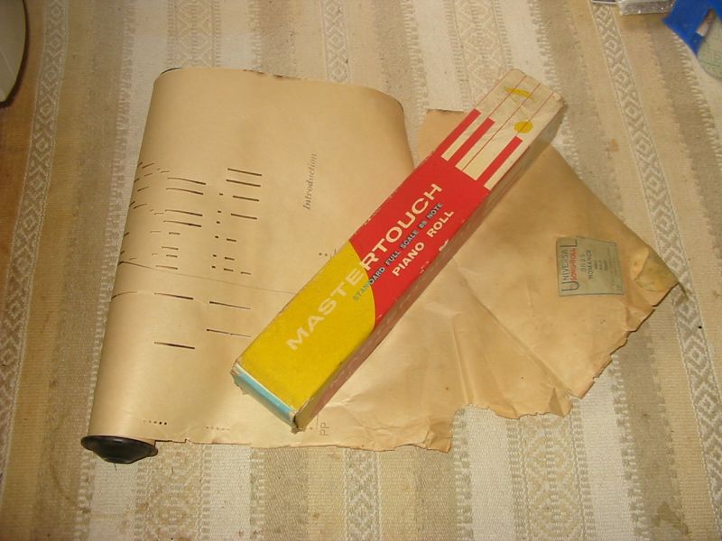
Yes, I find old 'data storage' systems fascinating. Here's another - a piano roll. It's far too delicate now to be actually used, but that's OK. I find it amusing - a kind of early semi-analogue punched tape system. The reader device was a bit bulky though!
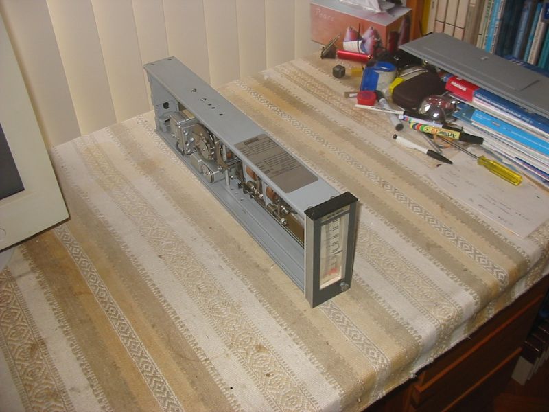
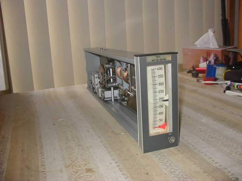
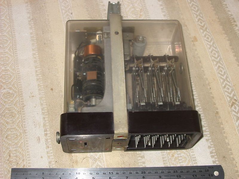
Speaking of analogue, this is not only analogue but also entirely air-powered. It's an industrial set-point controller, using pneumatic calculating circuits to implement a PID (proportional integral differential) control loop. Once again, a salvage from a site that was being demolished. It's very typical that things like this are simply bulldozed. At least, it is in Australia. No one ever seems to consider making them available to museums, or selling them off to anyone interested.
Personally, I'd like to see such careless destructiveness become some kind of legally recognised and punished act of criminal vandalism. But realistically I can't see it ever happening.
Front view. The control panels had rows of these, all destroyed but this one.
The black needle is adjusted with the 'SET' knob to the desired value, then this unit tries to keep the red measurement needle at that set point, by outputting a control signal to whatever actually runs the process. The 'PID' relates to the way the unit responds to errors, to achieve the best possible response without going into oscillation.
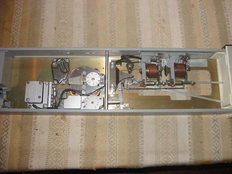
One side view. The copper bellows at the right are the needle drive/sensors, all pneumatic. "But where are the interconnecting pipes then?" you may wonder. How do the various parts in this device interconnect?
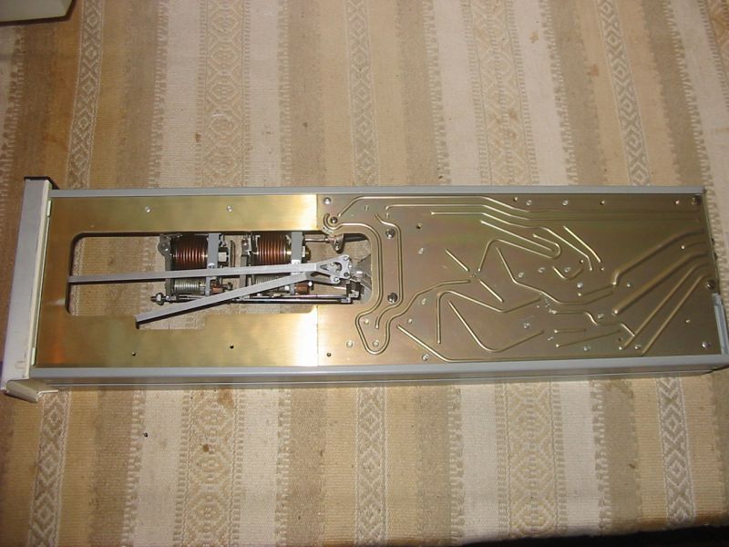
The answer: Interconnection is via a kind of pneumatic 'printed circuit.' This consists of two sheets of aluminium glued together. One is thick, with just a few holes through it. The other is thin, pressed to form the 'circuit traces'.

The sole external connection on the device. It's a pneumatic plug, that mated with a backplane the unit slid into.

Adjustments.
A huge old relay, built to never fail. Because if it did fail, bad train-crash type things might happen.