A bit more involved than expected
20121128 TerraHertz http://everist.org
Last week a friend who I owe a favour, told me the company he works for needs an unusual pivoting monitor-keyboard stand for
an equipment rack. And since I can build stuff, could I make one for them?
He sent me the rough specs, and reminded me of the stuff he's given me in the past, such as a bunch of obsolete stock that company was disposing of, and which was extremely useful to me.
So I said yes. Then it turned out they actually needed four. At least at this point I had the sense to say I'd want a small amount of money to cover costs. We agreed $100 each for the four would be OK.
This is why I could never make a living doing fabrication. I have abysmal ability to estimate how difficult things will be, how long they'll take, and what it will cost.
I started last Friday, it's now Thursday a week later, I've been working on this most of the time since including the weekend, and I'm maybe 70% finished.
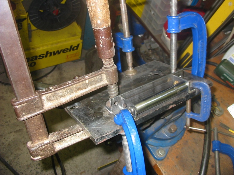
Ready to weld the first bracket. This bolts to the vertical frame of their trolley. The shiny cylinder is just an accurate spacer, to fix the bracket ends in place during welding. It's machined from a strut of an old car front shock absorber. Lovely polished steel, that has an outer layer of case hardening that does not like being turned in the lathe at all. The brass screws are to protect threaded holes from weld spatter.
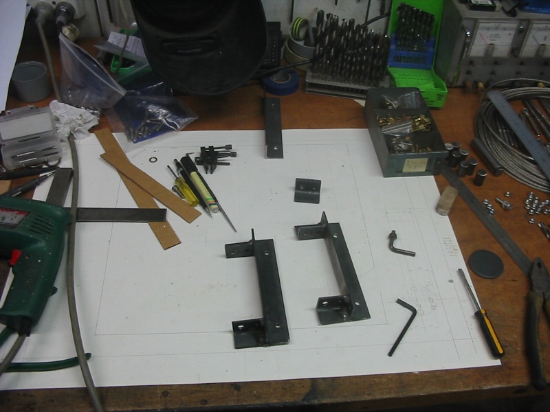
A couple of the brackets. And the full scale diagram I'd drawn to work on. Once I had that full size drawing, and some cutout puppets of the bits that had to fit, it turned out the space in their trolleys was a bit restricted. So the design was more difficult that I'd thought.
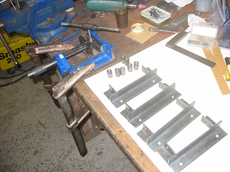
All four brackets welded, now tapping threads into the pivots. The old brown container with the white cap beside it on desk, contains Trefolex - a special lubricant for thread tapping. This was given to me by a machinist at my first full time job when I was about 20, and I'm still using it at age 57. A few years ago I found a big, full tin of Trefolex among rubble on the floor in a long-abandoned, ruined building. Apparently not one of the hundreds of people who'd stripped and trashed the place over the years had recognised it as something useful. Sad indicators of a civilization in decline.
Anyway I doubt I'll live long enough to run out of this little container.
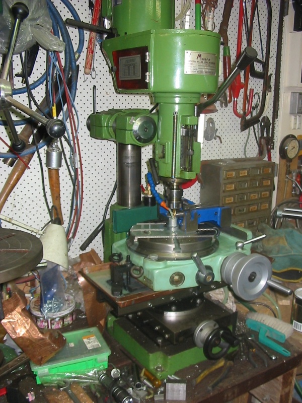
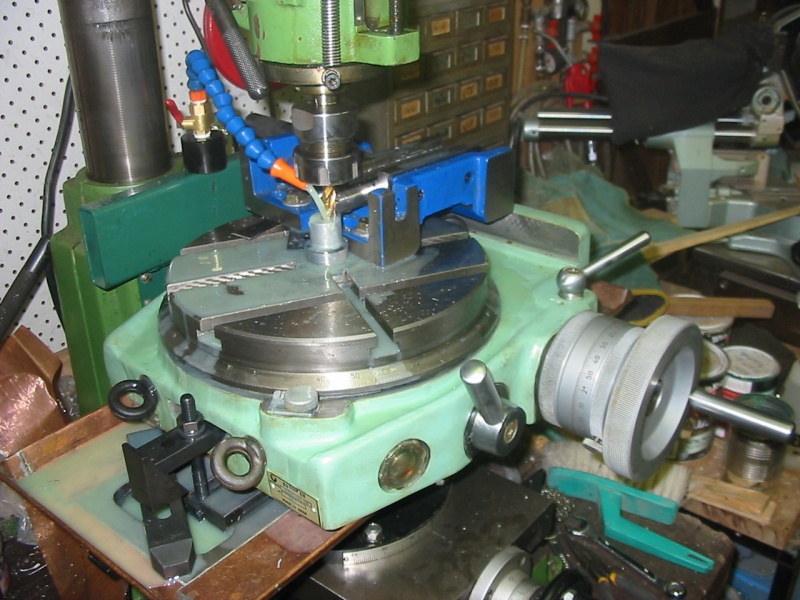
Milling a curved end into one of the tube sections. This photo doesn't do justice to the amount of setup required. The rotary table (pale green) has been sitting in its original wooden shipping crate since I bought it sometime in the late 1990s. It's Russian manufacture, the importer was having an 'almost going out of business sale' and it was cheap. It's far too large for my small toy milling machine's bed, and I assumed I would never use it till the (imagined) distant day when I had enough money and a bigger workshop to buy a real milling machine.
But now I absolutely needed to mill a radius curve in the tube end. And so... get the crate down off a shelf (too heavy for me, needed my son's assistance), inspect, fill its internal oil reservoir, figure out how to mount it (there are wooden blocks underneath to pack it up over the mill table's copper-sheet cutting-fluid tray), and find that there's just enough length in the table's T-slots to improvise clamping for the rotary table.
Next, needed a way to position the table center relative to the milling bit. The center of the rotary table is a hole, that turns out to be a #4 Morse taper. I happened to have a taper adapter, #4 to next smaller size. But what I need here is a center pin. So I machined an aluminium bar with a morse taper, and put a threaded hole in the center of that. Jamb them both together and into the rotary table, and presto... Then bolt a machinist's vice to the rotary table and align the jaws to the table center.
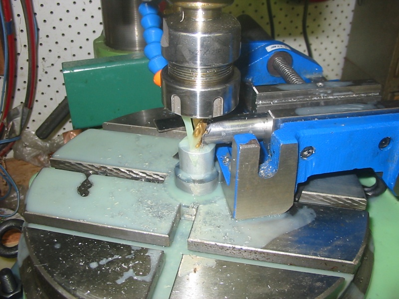
Cutting the radius curve in the end of a tube.
Same. You can see how close to impossible it was to clamp the rotary table down. The T-slot nut is barely in the end of the slot. Same at the other end.
A completed radius cut. The scribed line barely visible on the end of the aluminium plug is the diameter of the tube, that the cut tube seen here has to butt-join to.

Making four 'curved-face pressure washers.' These will be part of the structure for the monitor tilt angle pivot.
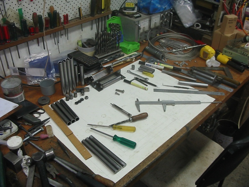
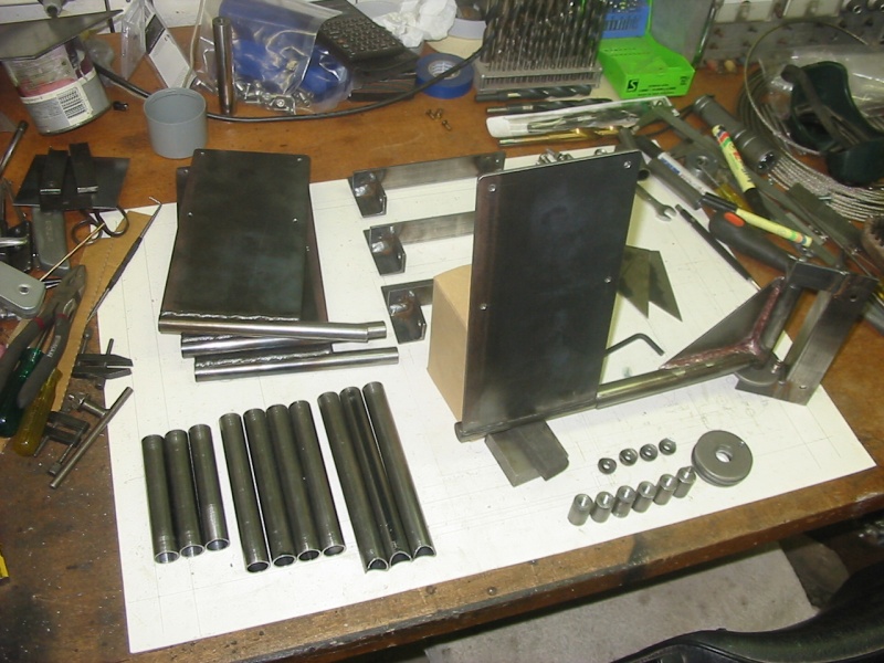
The bench, with more of the monitor stand components completed but not yet joined together. Still a long way to go.
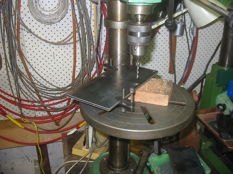
Drilling the VESA mounting holes for the back of the LCD monitors. Where ever possible I use transfer drilling - get one component drilled accurately, then use it as a drill template to do the others.
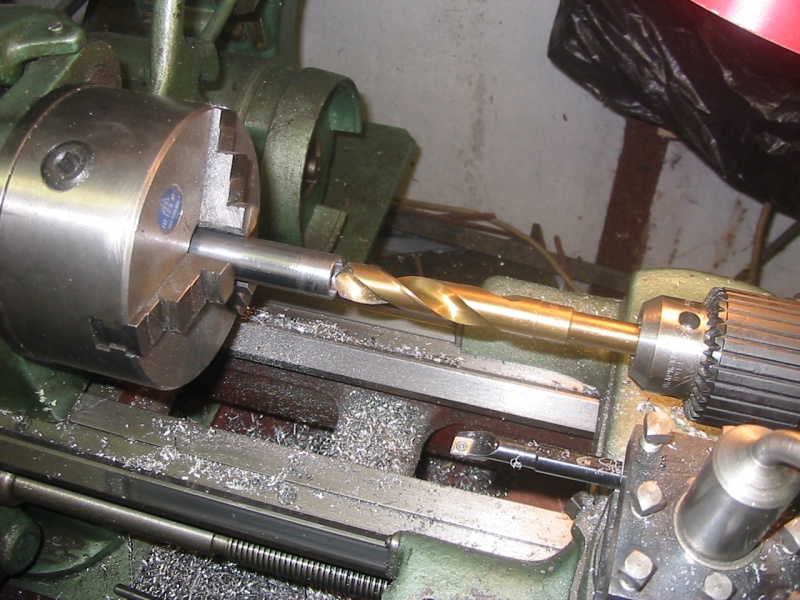
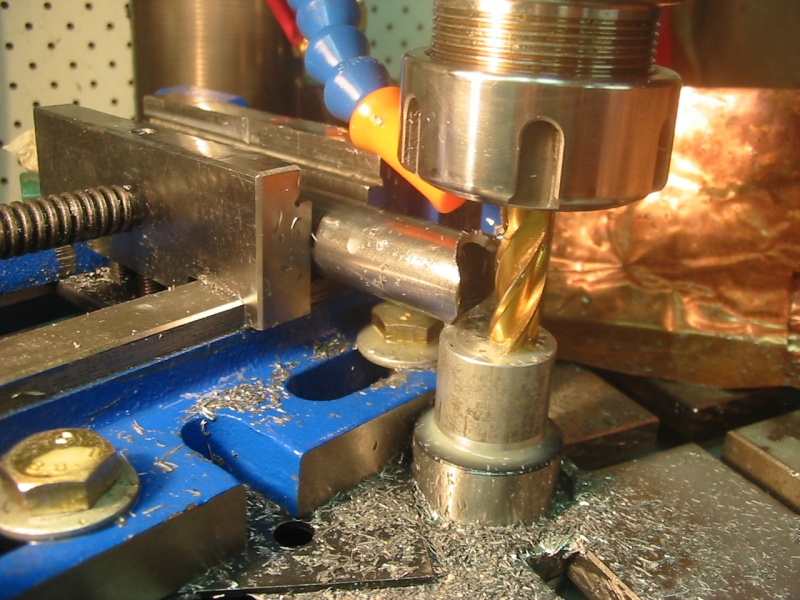
Boring out the inside diameter of some tube, for a good fit to the solid steel bar. All of the three pivots needed in each stand are done this way. At first used a boring bar to get a really close fit to the offcut bar I'd bought when figuring out how to make the stands. But I needed longer pivot depths than I could do with a small boring bar, and the round bar I bought later was a slightly different diameter anyway. So bought a 16mm drill.
Last night, most of the parts ready to assemble, except for the keyboard trays. The one pivot unit seen assembled is silver-soldered rather than welded, since I know that MIG welding the fairly thin walled steel tubes would distort them too much for the pivot pins to still fit the machined inner diameter. Even silver-soldering slightly distorted this one. The surface colouring doesn't matter, it will all be painted.